EP2852449B1 - Trennvorrichtung - Google Patents
Trennvorrichtung Download PDFInfo
- Publication number
- EP2852449B1 EP2852449B1 EP13725437.1A EP13725437A EP2852449B1 EP 2852449 B1 EP2852449 B1 EP 2852449B1 EP 13725437 A EP13725437 A EP 13725437A EP 2852449 B1 EP2852449 B1 EP 2852449B1
- Authority
- EP
- European Patent Office
- Prior art keywords
- chamber
- flow
- liquid
- separator device
- directing
- Prior art date
- Legal status (The legal status is an assumption and is not a legal conclusion. Google has not performed a legal analysis and makes no representation as to the accuracy of the status listed.)
- Active
Links
Images


Classifications
-
- B—PERFORMING OPERATIONS; TRANSPORTING
- B01—PHYSICAL OR CHEMICAL PROCESSES OR APPARATUS IN GENERAL
- B01D—SEPARATION
- B01D21/00—Separation of suspended solid particles from liquids by sedimentation
-
- B—PERFORMING OPERATIONS; TRANSPORTING
- B04—CENTRIFUGAL APPARATUS OR MACHINES FOR CARRYING-OUT PHYSICAL OR CHEMICAL PROCESSES
- B04C—APPARATUS USING FREE VORTEX FLOW, e.g. CYCLONES
- B04C5/00—Apparatus in which the axial direction of the vortex is reversed
- B04C5/14—Construction of the underflow ducting; Apex constructions; Discharge arrangements ; discharge through sidewall provided with a few slits or perforations
-
- B—PERFORMING OPERATIONS; TRANSPORTING
- B01—PHYSICAL OR CHEMICAL PROCESSES OR APPARATUS IN GENERAL
- B01D—SEPARATION
- B01D21/00—Separation of suspended solid particles from liquids by sedimentation
- B01D21/0009—Settling tanks making use of electricity or magnetism
-
- B—PERFORMING OPERATIONS; TRANSPORTING
- B01—PHYSICAL OR CHEMICAL PROCESSES OR APPARATUS IN GENERAL
- B01D—SEPARATION
- B01D21/00—Separation of suspended solid particles from liquids by sedimentation
- B01D21/0024—Inlets or outlets provided with regulating devices, e.g. valves, flaps
-
- B—PERFORMING OPERATIONS; TRANSPORTING
- B01—PHYSICAL OR CHEMICAL PROCESSES OR APPARATUS IN GENERAL
- B01D—SEPARATION
- B01D21/00—Separation of suspended solid particles from liquids by sedimentation
- B01D21/003—Sedimentation tanks provided with a plurality of compartments separated by a partition wall
- B01D21/0036—Horizontal partition walls
-
- B—PERFORMING OPERATIONS; TRANSPORTING
- B01—PHYSICAL OR CHEMICAL PROCESSES OR APPARATUS IN GENERAL
- B01D—SEPARATION
- B01D21/00—Separation of suspended solid particles from liquids by sedimentation
- B01D21/0039—Settling tanks provided with contact surfaces, e.g. baffles, particles
-
- B—PERFORMING OPERATIONS; TRANSPORTING
- B01—PHYSICAL OR CHEMICAL PROCESSES OR APPARATUS IN GENERAL
- B01D—SEPARATION
- B01D21/00—Separation of suspended solid particles from liquids by sedimentation
- B01D21/0039—Settling tanks provided with contact surfaces, e.g. baffles, particles
- B01D21/0042—Baffles or guide plates
-
- B—PERFORMING OPERATIONS; TRANSPORTING
- B01—PHYSICAL OR CHEMICAL PROCESSES OR APPARATUS IN GENERAL
- B01D—SEPARATION
- B01D21/00—Separation of suspended solid particles from liquids by sedimentation
- B01D21/0039—Settling tanks provided with contact surfaces, e.g. baffles, particles
- B01D21/0045—Plurality of essentially parallel plates
-
- B—PERFORMING OPERATIONS; TRANSPORTING
- B01—PHYSICAL OR CHEMICAL PROCESSES OR APPARATUS IN GENERAL
- B01D—SEPARATION
- B01D21/00—Separation of suspended solid particles from liquids by sedimentation
- B01D21/0039—Settling tanks provided with contact surfaces, e.g. baffles, particles
- B01D21/0066—Settling tanks provided with contact surfaces, e.g. baffles, particles with a meandering flow pattern of liquid or solid particles
-
- B—PERFORMING OPERATIONS; TRANSPORTING
- B01—PHYSICAL OR CHEMICAL PROCESSES OR APPARATUS IN GENERAL
- B01D—SEPARATION
- B01D21/00—Separation of suspended solid particles from liquids by sedimentation
- B01D21/0087—Settling tanks provided with means for ensuring a special flow pattern, e.g. even inflow or outflow
-
- B—PERFORMING OPERATIONS; TRANSPORTING
- B01—PHYSICAL OR CHEMICAL PROCESSES OR APPARATUS IN GENERAL
- B01D—SEPARATION
- B01D21/00—Separation of suspended solid particles from liquids by sedimentation
- B01D21/24—Feed or discharge mechanisms for settling tanks
-
- B—PERFORMING OPERATIONS; TRANSPORTING
- B01—PHYSICAL OR CHEMICAL PROCESSES OR APPARATUS IN GENERAL
- B01D—SEPARATION
- B01D21/00—Separation of suspended solid particles from liquids by sedimentation
- B01D21/24—Feed or discharge mechanisms for settling tanks
- B01D21/2405—Feed mechanisms for settling tanks
- B01D21/2411—Feed mechanisms for settling tanks having a tangential inlet
-
- B—PERFORMING OPERATIONS; TRANSPORTING
- B01—PHYSICAL OR CHEMICAL PROCESSES OR APPARATUS IN GENERAL
- B01D—SEPARATION
- B01D21/00—Separation of suspended solid particles from liquids by sedimentation
- B01D21/24—Feed or discharge mechanisms for settling tanks
- B01D21/245—Discharge mechanisms for the sediments
- B01D21/2483—Means or provisions for manually removing the sediments
-
- B—PERFORMING OPERATIONS; TRANSPORTING
- B01—PHYSICAL OR CHEMICAL PROCESSES OR APPARATUS IN GENERAL
- B01D—SEPARATION
- B01D21/00—Separation of suspended solid particles from liquids by sedimentation
- B01D21/26—Separation of sediment aided by centrifugal force or centripetal force
-
- B—PERFORMING OPERATIONS; TRANSPORTING
- B01—PHYSICAL OR CHEMICAL PROCESSES OR APPARATUS IN GENERAL
- B01D—SEPARATION
- B01D21/00—Separation of suspended solid particles from liquids by sedimentation
- B01D21/26—Separation of sediment aided by centrifugal force or centripetal force
- B01D21/267—Separation of sediment aided by centrifugal force or centripetal force by using a cyclone
-
- B—PERFORMING OPERATIONS; TRANSPORTING
- B01—PHYSICAL OR CHEMICAL PROCESSES OR APPARATUS IN GENERAL
- B01D—SEPARATION
- B01D29/00—Filters with filtering elements stationary during filtration, e.g. pressure or suction filters, not covered by groups B01D24/00 - B01D27/00; Filtering elements therefor
- B01D29/88—Filters with filtering elements stationary during filtration, e.g. pressure or suction filters, not covered by groups B01D24/00 - B01D27/00; Filtering elements therefor having feed or discharge devices
- B01D29/90—Filters with filtering elements stationary during filtration, e.g. pressure or suction filters, not covered by groups B01D24/00 - B01D27/00; Filtering elements therefor having feed or discharge devices for feeding
- B01D29/908—Filters with filtering elements stationary during filtration, e.g. pressure or suction filters, not covered by groups B01D24/00 - B01D27/00; Filtering elements therefor having feed or discharge devices for feeding provoking a tangential stream
-
- B—PERFORMING OPERATIONS; TRANSPORTING
- B01—PHYSICAL OR CHEMICAL PROCESSES OR APPARATUS IN GENERAL
- B01D—SEPARATION
- B01D35/00—Filtering devices having features not specifically covered by groups B01D24/00 - B01D33/00, or for applications not specifically covered by groups B01D24/00 - B01D33/00; Auxiliary devices for filtration; Filter housing constructions
- B01D35/06—Filters making use of electricity or magnetism
-
- B—PERFORMING OPERATIONS; TRANSPORTING
- B01—PHYSICAL OR CHEMICAL PROCESSES OR APPARATUS IN GENERAL
- B01D—SEPARATION
- B01D35/00—Filtering devices having features not specifically covered by groups B01D24/00 - B01D33/00, or for applications not specifically covered by groups B01D24/00 - B01D33/00; Auxiliary devices for filtration; Filter housing constructions
- B01D35/30—Filter housing constructions
- B01D35/301—Constructions of two or more housings
- B01D35/303—Constructions of two or more housings the housings being modular, e.g. standardised
-
- B—PERFORMING OPERATIONS; TRANSPORTING
- B03—SEPARATION OF SOLID MATERIALS USING LIQUIDS OR USING PNEUMATIC TABLES OR JIGS; MAGNETIC OR ELECTROSTATIC SEPARATION OF SOLID MATERIALS FROM SOLID MATERIALS OR FLUIDS; SEPARATION BY HIGH-VOLTAGE ELECTRIC FIELDS
- B03C—MAGNETIC OR ELECTROSTATIC SEPARATION OF SOLID MATERIALS FROM SOLID MATERIALS OR FLUIDS; SEPARATION BY HIGH-VOLTAGE ELECTRIC FIELDS
- B03C1/00—Magnetic separation
- B03C1/02—Magnetic separation acting directly on the substance being separated
- B03C1/035—Open gradient magnetic separators, i.e. separators in which the gap is unobstructed, characterised by the configuration of the gap
- B03C1/0355—Open gradient magnetic separators, i.e. separators in which the gap is unobstructed, characterised by the configuration of the gap using superconductive coils
-
- B—PERFORMING OPERATIONS; TRANSPORTING
- B03—SEPARATION OF SOLID MATERIALS USING LIQUIDS OR USING PNEUMATIC TABLES OR JIGS; MAGNETIC OR ELECTROSTATIC SEPARATION OF SOLID MATERIALS FROM SOLID MATERIALS OR FLUIDS; SEPARATION BY HIGH-VOLTAGE ELECTRIC FIELDS
- B03C—MAGNETIC OR ELECTROSTATIC SEPARATION OF SOLID MATERIALS FROM SOLID MATERIALS OR FLUIDS; SEPARATION BY HIGH-VOLTAGE ELECTRIC FIELDS
- B03C1/00—Magnetic separation
- B03C1/02—Magnetic separation acting directly on the substance being separated
- B03C1/10—Magnetic separation acting directly on the substance being separated with cylindrical material carriers
- B03C1/14—Magnetic separation acting directly on the substance being separated with cylindrical material carriers with non-movable magnets
-
- B—PERFORMING OPERATIONS; TRANSPORTING
- B03—SEPARATION OF SOLID MATERIALS USING LIQUIDS OR USING PNEUMATIC TABLES OR JIGS; MAGNETIC OR ELECTROSTATIC SEPARATION OF SOLID MATERIALS FROM SOLID MATERIALS OR FLUIDS; SEPARATION BY HIGH-VOLTAGE ELECTRIC FIELDS
- B03C—MAGNETIC OR ELECTROSTATIC SEPARATION OF SOLID MATERIALS FROM SOLID MATERIALS OR FLUIDS; SEPARATION BY HIGH-VOLTAGE ELECTRIC FIELDS
- B03C1/00—Magnetic separation
- B03C1/02—Magnetic separation acting directly on the substance being separated
- B03C1/28—Magnetic plugs and dipsticks
- B03C1/286—Magnetic plugs and dipsticks disposed at the inner circumference of a recipient, e.g. magnetic drain bolt
-
- B—PERFORMING OPERATIONS; TRANSPORTING
- B03—SEPARATION OF SOLID MATERIALS USING LIQUIDS OR USING PNEUMATIC TABLES OR JIGS; MAGNETIC OR ELECTROSTATIC SEPARATION OF SOLID MATERIALS FROM SOLID MATERIALS OR FLUIDS; SEPARATION BY HIGH-VOLTAGE ELECTRIC FIELDS
- B03C—MAGNETIC OR ELECTROSTATIC SEPARATION OF SOLID MATERIALS FROM SOLID MATERIALS OR FLUIDS; SEPARATION BY HIGH-VOLTAGE ELECTRIC FIELDS
- B03C1/00—Magnetic separation
- B03C1/02—Magnetic separation acting directly on the substance being separated
- B03C1/28—Magnetic plugs and dipsticks
- B03C1/288—Magnetic plugs and dipsticks disposed at the outer circumference of a recipient
-
- B—PERFORMING OPERATIONS; TRANSPORTING
- B03—SEPARATION OF SOLID MATERIALS USING LIQUIDS OR USING PNEUMATIC TABLES OR JIGS; MAGNETIC OR ELECTROSTATIC SEPARATION OF SOLID MATERIALS FROM SOLID MATERIALS OR FLUIDS; SEPARATION BY HIGH-VOLTAGE ELECTRIC FIELDS
- B03C—MAGNETIC OR ELECTROSTATIC SEPARATION OF SOLID MATERIALS FROM SOLID MATERIALS OR FLUIDS; SEPARATION BY HIGH-VOLTAGE ELECTRIC FIELDS
- B03C1/00—Magnetic separation
- B03C1/02—Magnetic separation acting directly on the substance being separated
- B03C1/30—Combinations with other devices, not otherwise provided for
-
- B—PERFORMING OPERATIONS; TRANSPORTING
- B04—CENTRIFUGAL APPARATUS OR MACHINES FOR CARRYING-OUT PHYSICAL OR CHEMICAL PROCESSES
- B04C—APPARATUS USING FREE VORTEX FLOW, e.g. CYCLONES
- B04C3/00—Apparatus in which the axial direction of the vortex flow following a screw-thread type line remains unchanged ; Devices in which one of the two discharge ducts returns centrally through the vortex chamber, a reverse-flow vortex being prevented by bulkheads in the central discharge duct
- B04C3/06—Construction of inlets or outlets to the vortex chamber
-
- B—PERFORMING OPERATIONS; TRANSPORTING
- B04—CENTRIFUGAL APPARATUS OR MACHINES FOR CARRYING-OUT PHYSICAL OR CHEMICAL PROCESSES
- B04C—APPARATUS USING FREE VORTEX FLOW, e.g. CYCLONES
- B04C5/00—Apparatus in which the axial direction of the vortex is reversed
- B04C5/14—Construction of the underflow ducting; Apex constructions; Discharge arrangements ; discharge through sidewall provided with a few slits or perforations
- B04C5/185—Dust collectors
-
- B—PERFORMING OPERATIONS; TRANSPORTING
- B21—MECHANICAL METAL-WORKING WITHOUT ESSENTIALLY REMOVING MATERIAL; PUNCHING METAL
- B21D—WORKING OR PROCESSING OF SHEET METAL OR METAL TUBES, RODS OR PROFILES WITHOUT ESSENTIALLY REMOVING MATERIAL; PUNCHING METAL
- B21D39/00—Application of procedures in order to connect objects or parts, e.g. coating with sheet metal otherwise than by plating; Tube expanders
- B21D39/04—Application of procedures in order to connect objects or parts, e.g. coating with sheet metal otherwise than by plating; Tube expanders of tubes with tubes; of tubes with rods
- B21D39/044—Application of procedures in order to connect objects or parts, e.g. coating with sheet metal otherwise than by plating; Tube expanders of tubes with tubes; of tubes with rods perpendicular
-
- B—PERFORMING OPERATIONS; TRANSPORTING
- B25—HAND TOOLS; PORTABLE POWER-DRIVEN TOOLS; MANIPULATORS
- B25B—TOOLS OR BENCH DEVICES NOT OTHERWISE PROVIDED FOR, FOR FASTENING, CONNECTING, DISENGAGING OR HOLDING
- B25B11/00—Work holders not covered by any preceding group in the subclass, e.g. magnetic work holders, vacuum work holders
- B25B11/02—Assembly jigs
-
- B—PERFORMING OPERATIONS; TRANSPORTING
- B25—HAND TOOLS; PORTABLE POWER-DRIVEN TOOLS; MANIPULATORS
- B25B—TOOLS OR BENCH DEVICES NOT OTHERWISE PROVIDED FOR, FOR FASTENING, CONNECTING, DISENGAGING OR HOLDING
- B25B13/00—Spanners; Wrenches
- B25B13/48—Spanners; Wrenches for special purposes
-
- B—PERFORMING OPERATIONS; TRANSPORTING
- B25—HAND TOOLS; PORTABLE POWER-DRIVEN TOOLS; MANIPULATORS
- B25B—TOOLS OR BENCH DEVICES NOT OTHERWISE PROVIDED FOR, FOR FASTENING, CONNECTING, DISENGAGING OR HOLDING
- B25B13/00—Spanners; Wrenches
- B25B13/48—Spanners; Wrenches for special purposes
- B25B13/481—Spanners; Wrenches for special purposes for operating in areas having limited access
-
- C—CHEMISTRY; METALLURGY
- C02—TREATMENT OF WATER, WASTE WATER, SEWAGE, OR SLUDGE
- C02F—TREATMENT OF WATER, WASTE WATER, SEWAGE, OR SLUDGE
- C02F1/00—Treatment of water, waste water, or sewage
- C02F1/48—Treatment of water, waste water, or sewage with magnetic or electric fields
- C02F1/488—Treatment of water, waste water, or sewage with magnetic or electric fields for separation of magnetic materials, e.g. magnetic flocculation
-
- E—FIXED CONSTRUCTIONS
- E03—WATER SUPPLY; SEWERAGE
- E03B—INSTALLATIONS OR METHODS FOR OBTAINING, COLLECTING, OR DISTRIBUTING WATER
- E03B7/00—Water main or service pipe systems
- E03B7/07—Arrangement of devices, e.g. filters, flow controls, measuring devices, siphons or valves, in the pipe systems
- E03B7/074—Arrangement of water treatment devices
-
- F—MECHANICAL ENGINEERING; LIGHTING; HEATING; WEAPONS; BLASTING
- F16—ENGINEERING ELEMENTS AND UNITS; GENERAL MEASURES FOR PRODUCING AND MAINTAINING EFFECTIVE FUNCTIONING OF MACHINES OR INSTALLATIONS; THERMAL INSULATION IN GENERAL
- F16L—PIPES; JOINTS OR FITTINGS FOR PIPES; SUPPORTS FOR PIPES, CABLES OR PROTECTIVE TUBING; MEANS FOR THERMAL INSULATION IN GENERAL
- F16L21/00—Joints with sleeve or socket
-
- F—MECHANICAL ENGINEERING; LIGHTING; HEATING; WEAPONS; BLASTING
- F16—ENGINEERING ELEMENTS AND UNITS; GENERAL MEASURES FOR PRODUCING AND MAINTAINING EFFECTIVE FUNCTIONING OF MACHINES OR INSTALLATIONS; THERMAL INSULATION IN GENERAL
- F16L—PIPES; JOINTS OR FITTINGS FOR PIPES; SUPPORTS FOR PIPES, CABLES OR PROTECTIVE TUBING; MEANS FOR THERMAL INSULATION IN GENERAL
- F16L29/00—Joints with fluid cut-off means
- F16L29/007—Joints with cut-off devices controlled separately
-
- F—MECHANICAL ENGINEERING; LIGHTING; HEATING; WEAPONS; BLASTING
- F16—ENGINEERING ELEMENTS AND UNITS; GENERAL MEASURES FOR PRODUCING AND MAINTAINING EFFECTIVE FUNCTIONING OF MACHINES OR INSTALLATIONS; THERMAL INSULATION IN GENERAL
- F16L—PIPES; JOINTS OR FITTINGS FOR PIPES; SUPPORTS FOR PIPES, CABLES OR PROTECTIVE TUBING; MEANS FOR THERMAL INSULATION IN GENERAL
- F16L55/00—Devices or appurtenances for use in, or in connection with, pipes or pipe systems
- F16L55/24—Preventing accumulation of dirt or other matter in pipes, e.g. by traps, by strainers
-
- F—MECHANICAL ENGINEERING; LIGHTING; HEATING; WEAPONS; BLASTING
- F17—STORING OR DISTRIBUTING GASES OR LIQUIDS
- F17D—PIPE-LINE SYSTEMS; PIPE-LINES
- F17D3/00—Arrangements for supervising or controlling working operations
- F17D3/16—Arrangements for supervising or controlling working operations for eliminating particles in suspension
-
- F—MECHANICAL ENGINEERING; LIGHTING; HEATING; WEAPONS; BLASTING
- F24—HEATING; RANGES; VENTILATING
- F24D—DOMESTIC- OR SPACE-HEATING SYSTEMS, e.g. CENTRAL HEATING SYSTEMS; DOMESTIC HOT-WATER SUPPLY SYSTEMS; ELEMENTS OR COMPONENTS THEREFOR
- F24D19/00—Details
-
- F—MECHANICAL ENGINEERING; LIGHTING; HEATING; WEAPONS; BLASTING
- F24—HEATING; RANGES; VENTILATING
- F24D—DOMESTIC- OR SPACE-HEATING SYSTEMS, e.g. CENTRAL HEATING SYSTEMS; DOMESTIC HOT-WATER SUPPLY SYSTEMS; ELEMENTS OR COMPONENTS THEREFOR
- F24D19/00—Details
- F24D19/0092—Devices for preventing or removing corrosion, slime or scale
-
- B—PERFORMING OPERATIONS; TRANSPORTING
- B01—PHYSICAL OR CHEMICAL PROCESSES OR APPARATUS IN GENERAL
- B01D—SEPARATION
- B01D2201/00—Details relating to filtering apparatus
- B01D2201/30—Filter housing constructions
- B01D2201/301—Details of removable closures, lids, caps, filter heads
- B01D2201/302—Details of removable closures, lids, caps, filter heads having inlet or outlet ports
-
- B—PERFORMING OPERATIONS; TRANSPORTING
- B01—PHYSICAL OR CHEMICAL PROCESSES OR APPARATUS IN GENERAL
- B01D—SEPARATION
- B01D2201/00—Details relating to filtering apparatus
- B01D2201/40—Special measures for connecting different parts of the filter
- B01D2201/4023—Means for connecting filter housings to supports
-
- B—PERFORMING OPERATIONS; TRANSPORTING
- B01—PHYSICAL OR CHEMICAL PROCESSES OR APPARATUS IN GENERAL
- B01D—SEPARATION
- B01D2221/00—Applications of separation devices
- B01D2221/02—Small separation devices for domestic application, e.g. for canteens, industrial kitchen, washing machines
-
- B—PERFORMING OPERATIONS; TRANSPORTING
- B03—SEPARATION OF SOLID MATERIALS USING LIQUIDS OR USING PNEUMATIC TABLES OR JIGS; MAGNETIC OR ELECTROSTATIC SEPARATION OF SOLID MATERIALS FROM SOLID MATERIALS OR FLUIDS; SEPARATION BY HIGH-VOLTAGE ELECTRIC FIELDS
- B03C—MAGNETIC OR ELECTROSTATIC SEPARATION OF SOLID MATERIALS FROM SOLID MATERIALS OR FLUIDS; SEPARATION BY HIGH-VOLTAGE ELECTRIC FIELDS
- B03C2201/00—Details of magnetic or electrostatic separation
- B03C2201/18—Magnetic separation whereby the particles are suspended in a liquid
-
- B—PERFORMING OPERATIONS; TRANSPORTING
- B03—SEPARATION OF SOLID MATERIALS USING LIQUIDS OR USING PNEUMATIC TABLES OR JIGS; MAGNETIC OR ELECTROSTATIC SEPARATION OF SOLID MATERIALS FROM SOLID MATERIALS OR FLUIDS; SEPARATION BY HIGH-VOLTAGE ELECTRIC FIELDS
- B03C—MAGNETIC OR ELECTROSTATIC SEPARATION OF SOLID MATERIALS FROM SOLID MATERIALS OR FLUIDS; SEPARATION BY HIGH-VOLTAGE ELECTRIC FIELDS
- B03C2201/00—Details of magnetic or electrostatic separation
- B03C2201/20—Magnetic separation of bulk or dry particles in mixtures
-
- B—PERFORMING OPERATIONS; TRANSPORTING
- B03—SEPARATION OF SOLID MATERIALS USING LIQUIDS OR USING PNEUMATIC TABLES OR JIGS; MAGNETIC OR ELECTROSTATIC SEPARATION OF SOLID MATERIALS FROM SOLID MATERIALS OR FLUIDS; SEPARATION BY HIGH-VOLTAGE ELECTRIC FIELDS
- B03C—MAGNETIC OR ELECTROSTATIC SEPARATION OF SOLID MATERIALS FROM SOLID MATERIALS OR FLUIDS; SEPARATION BY HIGH-VOLTAGE ELECTRIC FIELDS
- B03C2201/00—Details of magnetic or electrostatic separation
- B03C2201/28—Parts being designed to be removed for cleaning purposes
-
- C—CHEMISTRY; METALLURGY
- C02—TREATMENT OF WATER, WASTE WATER, SEWAGE, OR SLUDGE
- C02F—TREATMENT OF WATER, WASTE WATER, SEWAGE, OR SLUDGE
- C02F2101/00—Nature of the contaminant
- C02F2101/10—Inorganic compounds
- C02F2101/20—Heavy metals or heavy metal compounds
- C02F2101/203—Iron or iron compound
-
- C—CHEMISTRY; METALLURGY
- C02—TREATMENT OF WATER, WASTE WATER, SEWAGE, OR SLUDGE
- C02F—TREATMENT OF WATER, WASTE WATER, SEWAGE, OR SLUDGE
- C02F2201/00—Apparatus for treatment of water, waste water or sewage
- C02F2201/48—Devices for applying magnetic or electric fields
-
- C—CHEMISTRY; METALLURGY
- C02—TREATMENT OF WATER, WASTE WATER, SEWAGE, OR SLUDGE
- C02F—TREATMENT OF WATER, WASTE WATER, SEWAGE, OR SLUDGE
- C02F2303/00—Specific treatment goals
- C02F2303/22—Eliminating or preventing deposits, scale removal, scale prevention
-
- Y—GENERAL TAGGING OF NEW TECHNOLOGICAL DEVELOPMENTS; GENERAL TAGGING OF CROSS-SECTIONAL TECHNOLOGIES SPANNING OVER SEVERAL SECTIONS OF THE IPC; TECHNICAL SUBJECTS COVERED BY FORMER USPC CROSS-REFERENCE ART COLLECTIONS [XRACs] AND DIGESTS
- Y02—TECHNOLOGIES OR APPLICATIONS FOR MITIGATION OR ADAPTATION AGAINST CLIMATE CHANGE
- Y02B—CLIMATE CHANGE MITIGATION TECHNOLOGIES RELATED TO BUILDINGS, e.g. HOUSING, HOUSE APPLIANCES OR RELATED END-USER APPLICATIONS
- Y02B30/00—Energy efficient heating, ventilation or air conditioning [HVAC]
-
- Y—GENERAL TAGGING OF NEW TECHNOLOGICAL DEVELOPMENTS; GENERAL TAGGING OF CROSS-SECTIONAL TECHNOLOGIES SPANNING OVER SEVERAL SECTIONS OF THE IPC; TECHNICAL SUBJECTS COVERED BY FORMER USPC CROSS-REFERENCE ART COLLECTIONS [XRACs] AND DIGESTS
- Y02—TECHNOLOGIES OR APPLICATIONS FOR MITIGATION OR ADAPTATION AGAINST CLIMATE CHANGE
- Y02W—CLIMATE CHANGE MITIGATION TECHNOLOGIES RELATED TO WASTEWATER TREATMENT OR WASTE MANAGEMENT
- Y02W10/00—Technologies for wastewater treatment
- Y02W10/10—Biological treatment of water, waste water, or sewage
-
- Y—GENERAL TAGGING OF NEW TECHNOLOGICAL DEVELOPMENTS; GENERAL TAGGING OF CROSS-SECTIONAL TECHNOLOGIES SPANNING OVER SEVERAL SECTIONS OF THE IPC; TECHNICAL SUBJECTS COVERED BY FORMER USPC CROSS-REFERENCE ART COLLECTIONS [XRACs] AND DIGESTS
- Y10—TECHNICAL SUBJECTS COVERED BY FORMER USPC
- Y10T—TECHNICAL SUBJECTS COVERED BY FORMER US CLASSIFICATION
- Y10T137/00—Fluid handling
- Y10T137/794—With means for separating solid material from the fluid
Definitions
- the present invention relates to a separator device suitable for separating particles from a fluid flow and particularly but not exclusively to a separator device for use in a hydronic heating system.
- water is circulated by a pump through several radiators, possibly a heat exchanger in a hot water cylinder, and a boiler.
- solid particles for example, iron oxide
- Solid particles can also be present as contaminants in the water originally supplied to the system, and the water can become contaminated by dirt where an open expansion tank forms part of the system. These solid particles can cause malfunction if they build up in the boiler or pump, and reduce the effectiveness of the heating system by restricting the flow of water and clogging radiators.
- the water in a heating system should therefore be continually cleaned to remove solid particles as far as possible.
- Various devices are known for removing particles from suspension in a flow of water.
- these devices include a magnet for attracting ferrous particles, and may also include mechanical separation means for removing nonmagnetic particles.
- Nonmagnetic particles may be removed by causing a portion of the water to flow through a separation chamber, within which obstruction means are disposed to slow the flow. Particles will then fall out of suspension and become trapped in cavities, which can easily be cleaned during an annual service. Only a portion of the flow is slowed, so that the drop in fluid pressure across the device is minimised.
- Devices of this type are disclosed in the applicant's co-pending applications GB2486173 and GB2486172 .
- a simplified magnetic device is also known from GB2469145 .
- Known devices are designed to produce a slow flow rate in the separation chamber, whilst causing a minimal drop in fluid pressure across the unit. It is advantageous to produce separator devices which are small in size to enable them to be fitted in small spaces. This requires that the separator chamber must in turn be small in size, and the obstruction means disposed therein have a consequently limited ability to substantially slow the flow rate of fluid within. Since it is undesirable to place obstruction means outside of the separation chamber, due to the resultant pressure drop, there is a limit on the overall separation effectiveness of known devices.
- a removable screw-top is typically provided at the upper end of the cylindrical housing which, when removed, allows access to the inside of cylindrical housing.
- a removable insert is typically provided within the housing, which must be removed for cleaning.
- the removable insert is typically of similar longitudinal extent to the cylindrical housing. Therefore to allow the insert to be removed from the housing, the separator device must be installed where there is a vertical space between horizontal surfaces of at least twice the height of the housing. This requirement imposes an unwelcome constraint on the installer in terms of where the device may be installed, particularly where the separator device is being retrofitted to an existing installation. For example, there is often insufficient space between the bottom of a boiler and a counter top. In some cases it may simply not be possible to fit a device of suitable capacity which requires such a large vertical space.
- Separator devices are often fitted to a heating circuit via right-angle connectors which link the inlet and outlet of the device to pipework.
- the right-angle connectors may be installed on open ends of the pipework, and the separator device can then be pushed on to the right-angle connectors.
- cutting the pipe in exactly the right place and installing the right-angle connectors so that they correspond precisely with the inlet and outlet of the device is difficult to achieve.
- An installer may be tempted to attach the right-angle connectors to the separator device, afterwards screwing the connectors onto the pipework.
- there is a serious risk of damaging the separator device in this method since the torque of a spanner on a right-angle connector may be sufficient to break an inlet or outlet port from the separator.
- a separator device for use in a hydronic heating system to remove particles from suspension in a liquid as claimed in claim 1.
- Reversing the flow of fluid so that the fluid flows in the first and second chambers are counter-rotating serves to further reduce the flow rate in the second chamber, whilst ensuring that the overall pressure drop across the device is minimised. This increases the effectiveness with which small solid particles may be separated from the liquid.
- a third chamber is provided, being apertured for ingress and egress of fluid from at least one of the first chamber and the second chamber, and means being provided for directing a flow in the third chamber.
- the means for directing a flow may set up a swirl in the third chamber.
- the flow in the third chamber may be in substantially the same direction as the flow in the second chamber, and the first chamber may be disposed between the second and third chambers.
- the flow may be reversed when it passes from the first chamber to the second chamber and, where a third chamber is provided, flow may be reversed where it passes from the first chamber to the third chamber.
- Providing a third chamber allows two chambers to act as separating chambers, with obstruction means being provided to slow the flow.
- the remaining chamber maintains a substantially unobstructed swirling flow of fluid between the inlet and the outlet, and contains a sleeved magnet providing separation of magnetic particles in the swirling flow.
- Providing two separating chambers increases the overall effectiveness of the device, since more particles will be separated from the liquid.
- positioning chambers near both top and bottom ends of a separator device, with the first unobstructed chamber in the centre ensures that effective separation is achieved wherever the inlet to the device is located, allowing the apertures in the housing to be used as inlet and outlet either way around, affording flexibility to the installer.
- flow in the separating chambers is in the opposite direction to the swirl in the unobstructed first chamber, as reversing the direction of flow on entry to the or each separation chamber assists in slowing the flow within the separation chamber(s).
- the construction of a device with three chambers may conveniently be such that the first, second and third chambers share a single central axis.
- the central axis may be oriented vertically in use, so that the second and third chambers are at the top and bottom of the device.
- the means for directing flow or setting up a swirl within at least one of the chambers may be formed integrally with a wall or other barrier separating that chamber from another chamber.
- the means for directing flow of liquid within at least one of the chambers may comprise apertures in the chamber having the form of curved slots.
- Curved slots are advantageous since they may be positioned to deflect a flow of liquid into a separating chamber, and also to reverse the direction of the liquid flow.
- the means for setting up a swirl of liquid within at least one of the chambers may comprise of at least one flow guide extending from a wall of the chamber, adjacent to at least one aperture in the chamber wall.
- the flow guide or guides may form an angled deflector overhanging each aperture, and may extend below the chamber wall, into the chamber in which swirl is being set up.
- Opposing flows or swirls of liquid may be set up in at least one of the second chamber and, where provided, the third chamber. This may be achieved by reversing the flow as it passes between the first chamber and the second or third chamber, and reversing the flow again within the second or third chamber.
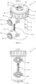
- a separator device for separating particles from suspension in a fluid is indicated generally at 10.
- a housing 12 is provided, comprising of a body portion 14 and a removable closure portion 16.
- the body portion is substantially a cylindrical shell open at the upper end, that is, the body portion 14 comprises a floor and a wall 17, and defines a main chamber 19.
- the upper end of the wall 17 of the body portion 14 is formed with a male thread 18 and, directly below the male thread, a circumferential rim 20.
- the closure portion 16 is in the form of a screw-on cap comprising a circular planar roof 26 and a circumferential wall 28 extending below the edge of the roof.
- a thread 22 is formed on the interior surface of the wall 28, for co-operating with the male thread 18 at the upper end of the wall 17 of the housing body portion 14.
- a plurality of recesses 24 are provided spaced uniformly around the outside of the wall 28 of the closure portion 16 in order to assist a user in gripping the closure portion 16 to effect closure and removal.
- a recess 30 is provided around the edge of the underside of the roof 26 of the closure portion 16.
- a rubber O-ring 32 sits within the recess 30, around half of the height of the O-ring 32 extending below the underside of the roof 26.
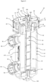
- An inlet and an outlet are provided as first and second hollow cylindrical sockets 96 in the wall 17 of the housing body 14, each extending perpendicular to the same tangent of the cylindrical body, that is, the sockets extend outwardly from the wall of the housing 14 and are parallel to each other on a diameter of the housing 12.
- John Guest Speedfit (RTM) connectors 98 are provided within the sockets 96, allowing easy fitting to a heating circuit.
- the sockets 96 receive sections of pipe, and the John Guest Speedfit (RTM) connectors 98 grip the pipe sections and form a sealed connection.
- the John Guest Speedfit (RTM) connectors 98 include collets 99 which, when pushed inwardly towards the housing body, release the grip on the pipe, allowing removal.
- the John Guest Speedfit (RTM) connectors allow for easy fitting and removal of the separator device 10 from a heating circuit.
- the parallel inlet and outlet sockets 96 are aligned on the same radial plane and enable easy fitting to a heating circuit, since the inlet and outlet will be in the same straight pipe line when the device is installed.
- a flat raised section 170 is provided on the curved surface of the housing body 14, between the inlet and outlet 96.
- Deflectors 100 are provided within each of the sockets 96 in the cylindrical housing 12.
- the deflectors 100 block a portion of each socket 96, directing the flow on the inlet to one side and resulting in a swirling flow within the main chamber 19.
- the edges of the deflectors 100 are at an angle of around 10° from the vertical, so as to divert water slightly vertically as well as horizontally. Providing deflectors 100 in both sockets 96 allows either to be used as the inlet, affording additional flexibility to the installer.
- a bleed valve assembly 102 is provided through the centre of the screw-on cap 16 and is screwed into a plug 50 within the housing 12.
- the bleed valve assembly includes a head portion 106 and a body portion 108, the head portion 106 being of greater diameter than the body portion 108, so that the body portion 108 but not the head portion 106 will fit through a circular aperture in the centre of the roof 26 of the closure portion 16 of the housing 12.
- a passage 120 is provided through the centre of the head and body portions 106, 108 and a screw-in bleed valve 121 screws into and seals the passage 120.
- a drain valve 116 comprising of a screw-in plug with seal is provided in the floor of the housing body 14.
- the separator device 10 When the heating system is serviced, the separator device 10 is isolated from the heating circuit, and the bleed valve 121 and drain valve 116 are opened to drain fluid from the housing 12. The drain valve 116 is then closed, and the system can be dosed with a corrosion inhibitor via the bleed valve passage 120. A supply line can be secured onto the thread of the head portion. The separator device 10 is then reconnected to the heating circuit, air being forced out of the bleed valve 102. When all the air has been removed the bleed valve 121 is closed, and the system refilled and/or re-pressurised as necessary.
- an insert 34 is removably contained within the housing 12.
- the insert comprises a central section 36 formed as a hollow cylinder, a first separation chamber 38 at an upper end of the insert and a second separation chamber 40 at a lower end of the insert, as viewed and installed in the housing.
- the upper and lower separation chambers 38, 40 are substantially cylindrical and share a central axis with the central section 36.
- the upper and lower separation chambers 38, 40 are sized to almost completely extend to the full interior diameter of the housing body 14.
- the hollow cylindrical central section 36 has a curved wall which is approximately 0.65mm thick.
- Four equally spaced reinforcing ribs 37 are provided, each around the circumference of the outer surface of the cylindrical central section 36.
- Four equally spaced reinforcing spines 33 are provided perpendicular to the ribs 37.
- the ribs 37 and spines 33 define rectangular panels 35.
- a cylindrical magnet is provided inside the hollow central section 36 of the insert 34, the central section forming a sheath around the magnet.
- the magnet attracts ferrous particles from the swirling flow of the liquid in the main chamber 19, the ferrous particles collecting in the panels 35 on the outer surface of the central sheath section 36 of the insert 34.
- the insert 34 may be removed from the housing 12, and the magnet removed from within the central sheath section 36. With the magnet removed, ferrous particles will easily fall away for disposal.
- the ribs and spines are required because the wall of the central section 36 is thin, to improve the effect of the magnet on the flow.
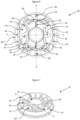
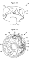
- the upper separation chamber 38 is formed as a cylindrical shell with an open top end, that is, a circular tray having a floor 44 and a single curved wall 46.
- the floor 44 has a circular aperture at its centre which has the same interior diameter as the hollow central section 36 of the sheath 34.
- protrusions 48 extend from the floor 44, the protrusions 48 having a vertical extent matching the vertical extent of the wall 46.
- the protrusions 48 form interior walls which define passageways within the upper separation chamber 38.
- the arrangement of the protrusions 48 is best shown in Figures 6 and 13 .
- the arrangement is reflectively symmetrical about two orthogonal axes A-A, B-B.
- Two protrusions of a first type 56 face each other.
- the protrusions of the first type 56 are formed of a curved wall 58 comprising substantially 90° of a circle arc, with a radius of curvature slightly smaller than the radius of the upper separation chamber 38, and a straight wall 60 extending inwardly from the centre of the curved wall 58 towards the centre of the chamber 38.
- Approximately one third of the length of the straight wall 60 extends beyond a straight line C-C between the ends of the curved section 58.
- the concave faces of the curved walls 58 face each other.
- the protrusions of the first type 56 are positioned with the straight wall 60 on a diameter B-B of the upper separation chamber 38, and so that the curved wall 58 does not touch the wall 46 of the upper separation chamber 38, enabling water to flow around all sides of the protrusions 56.
- the protrusions of a second type 62 face each other at 90° to the protrusions of the first type 56.
- the protrusions of the second type 62 each comprise a stem 66 extending from the wall 46 of the upper separation chamber 38 towards the centre of the chamber 38, and two hook-shaped walls 64.
- the stem 66 widens as it approaches the centre of the upper separation chamber 38, where the stem 66 meets the surface of the plug 50, curving around the surface of the plug.
- the hook-shaped walls 64 extend from either side of the stem 66 where it meets the plug 50, at an angle of around 55° from the stem, so that the hook-shaped walls 64 curve back towards the outside wall 46 of the upper separation chamber 38. Before the hook-shaped walls 64 meet the wall 46 of the upper separation chamber 38, they curve around 90° in the direction away from the stem 66, forming a hooked end.
- the extent of the hook after the 90° curve is substantially half of the extent of the hook before the curve.
- the stems 66 of the protrusions of the second type 62 together with the plug 50 form a wall extending across diameter A-A of the upper separation chamber 38 and dividing the upper separation chamber 38 into two halves.
- the upper separation chamber 38 is reflectively symmetrical about diameters A-A and B-B, and is also rotationally symmetrical about its centre.
- Two straight protrusions 68 having similar vertical extent to the above mentioned protrusions 56, 62 and to the wall 46 of the upper separation chamber 38, are disposed adjacent to the wall 46 on the diameter B-B of the upper separation chamber 38, projecting inwardly towards the centre of the upper separation chamber 38.
- slots 118 are provided in the upper separation chamber 38, one of which is best shown in Figure 4 .
- the slots 118 guide flow upwardly into the first separation chamber 38, in opposing arcuate directions, and extend through the side wall 46. That is, two guide flow upwardly in one arcuate direction, and the other two in the opposing direction, for guiding flow into the upper separation chamber 38 irrespective of the direction of swirl within the main chamber 19.
- Two straight protrusions 63 having slightly shorter vertical extent than the wall 46 of the upper separation chamber 38, are disposed on each of two chords of the circular chamber 38, each protrusion 63 forming a wall separating the arcuate slots 118 in the wall 46 from the rest of the upper separation chamber 38.
- the liquid changes direction when it hits the stem 66 of the protrusions of the second type 62, and then flows over the top of the straight protrusions 63.
- the flow continues between and around protrusions 56, 62, 68.
- the liquid flow is slowed by the obstruction of the protrusions 56, 62, 68, and in particular is slowed when it flows between the protrusion of the first type 56 and the protrusion of the second type 62, again changing direction in the area indicated at 65 in Figure 13 .
- Arrows in Figure 13 show the liquid flow through the upper separation chamber 38.
- a portion of flow in the housing is thus guided into the upper separation chamber 38, where it is very substantially slowed. This is done without causing a significant obstruction in the main chamber 19 between the inlet and outlet of the device.
- the net flow of liquid through the chamber is indicated by the arrow in Figure 13 , although it is appreciated that eddies and reverse flows will be present due to the obstruction means.
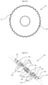
- the lower separation chamber 40 is formed as a tray 70, best seen in Figure 7 , which is detachable from a lid 72.
- the lid 72 is an integral part of the removable insert 34.
- the tray 70 is substantially toroidal with an inner wall 76, an outer wall 78 and a floor 80.
- the tray 70 has an outer diameter just less than the interior diameter of the housing body 14 and an inner diameter substantially matching the external diameter of the central section 36 of the removable insert 34.
- a plurality of planar walls 82 extend from the tray floor 80, each wall 82 joining the outer tray wall 78 to the inner tray wall 76, and each having a vertical extent just less than the vertical extent of the tray walls 76, 78, so that water can flow over, but not under or around the planar walls 82.
- the planar walls 82 are fourteen in number, and are spaced evenly around the toroidal tray 70 at sixteenths of its circumference, two sixteenths being without walls 82, those two sixteenths being opposite each other and the arrangement of walls 82 being reflectively and rotationally symmetrical about a diameter D-D upon which the sixteenths without planar walls 82 lie.
- the planar walls 82 are arranged in two sections, each section having seven walls 82.
- Substantially cylindrical protrusions 84 extend from the tray floor 80 and are coincident with the planar walls 82, so that that the cylindrical protrusions 84 extend through and above the substantially planar walls 82.
- the planar walls 82 at the ends of the sections are coincident with two cylindrical protrusions 84, as is every second wall 82 in each section, the remaining planar walls 82 being coincident with a single cylindrical protrusion 84.
- the cylindrical protrusion 84 is at the centre of the wall 82, equidistant from the inner and outer walls 76, 78 of the toroidal tray.
- a wall 82 has two cylindrical protrusions 84
- the distance between a first cylindrical protrusion and the outer tray wall 78 is equal to the distance between a second cylindrical protrusion and the inner tray wall 76.
- Each aforementioned distance is approximately one quarter of the distance between the inner and outer walls 76, 78.
- the lid 72 of the lower separation chamber 40 is formed as an annular roof 86 surrounding the central section 36 of the insert 34, with a wall 88 extending below the edge of the roof 86.
- the interior diameter of the lid 72 is substantially matching the exterior diameter of the tray 70 of the lower separation chamber so that the lid 72 fits over the tray 70.
- Apertures 89 are provided in the roof 86 of the lid 72 at either side of a radius, and are formed as two elongate rectangles, each with a longitudinal extent just less than the distance between the inner and outer sides of the annular roof 86, and the longitudinal axes of each being parallel with each other.
- the two rectangular apertures 89 are together reflectively symmetrical about a radial axis halfway between the apertures.
- a flow guide 90 extends upwardly from the upper surface of the roof 86 of the lid 72, on the radial axis of symmetry between the apertures, thus forming a wall between the apertures.
- the flow guide 90 becomes wider as it extends upwards, so that it forms a curved deflector adjacent to and overhanging each aperture.
- the flow guide 90 also extends downwardly from the roof 86 of the lid 72, almost meeting the floor 80 of the lower separation chamber 40, as shown in Figure 14 .
- the flow guide 90 therefore deflects a portion of the swirling flow downwards into the lower separation chamber 40, and reverses the direction of swirl in the lower separation chamber 40, irrespective of the direction of swirl within the housing 12.
- the tray 70 On the diameter D-D of the tray 70 which forms the space between the two sections of seven planar walls 82, two cylindrical pins 92 are provided near the top of the outer wall 78, extending outwardly from the outer wall 78.
- Co-operating slots 94 are provided in the walls 88 of the lid 72 extending vertically from the base of the lid wall and then laterally. In use, the tray 70 is slotted onto the lid 72 and then rotated to lock the tray 70 to the lid 72, in the manner of a bayonet connector.
- the separator device shown in the Figures and described above provides for three counter-rotating flows. Eddies and reverse swirls could occur in any one of the chambers, but the overall flow direction is as indicated.
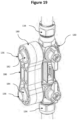
- the fitment 130 comprises first and second sockets 132 for accepting the open ends of pipes, a screw compression fitting 134 of well-known design on each socket 132 for forming a sealed connection with the pipe ends, and first and second pipe portions 136 fluidly connected respectively to the first and second pipe sockets, for fitting to the Speedfit (RTM) connectors 98 in the inlet and outlet 96 on the housing 12 of the separator device 10.
- RTM Speedfit
- a first valve 138 can be operated to break the fluid connection between the first pipe socket 132 and the first pipe portion 136
- a second valve 140 can be operated to break the fluid connection between the second pipe socket 132 and the second pipe portion 136.
- One of the two sockets 132 has a greater pipe receiving depth than the other, for example, twice the pipe receiving depth.
- Plugs 142 are provided on the backs of the pipe sockets 132.
- the plugs include a circular section 143 adjacent to the back of the pipe socket 132, and a square dog section 145 at the end of each plug 142.
- a recess 147 is provided around the curved surface of the circular section 143, and an O-ring 149 fits within the recess, protruding beyond the curved surface.
- a spacer 144 is provided for fitting between the backs of the first and second pipe sockets 132.
- the spacer 144 is sized to ensure that, when it is fitted, the pipe portions 136 on the fitment 130 are the same distance apart as the Speedfit (RTM) connectors 98 in the sockets 96 on the housing 12 of the separator device 10.
- the spacer 144 is formed substantially as a cylinder. Recesses 146 are provided on an outer wall 152 of the spacer 144 to provide torsional rigidity without increased mass.
- a socket 148 extends through the spacer from the top to the bottom, and is in the shape of a circle with two opposing truncated segments. At either end of the spacer 144, the socket 148 has sections which are circular without truncated segments. The circular end sections of the socket are sized to receive the circular sections 143 of the plugs 142. The circular sections 143 of the plugs 142 will not fit through the parts of the socket 148 having truncated segments, however the square sections 145 of the plugs 142 do fit into the truncated socket sections.
- the square end dog section 145 of the plug 142 When a plug 142 is inserted into a socket 148, the square end dog section 145 of the plug 142 will be received into the portion of the socket 148 which has truncated segments. Turning forces which act upon one of the compression fittings 134 will therefore be transmitted through the spacer to the other compression fitting 134.
- the dog may have a different cross section if desired, such as a hexagon.
- the O-ring 149 on the plug 142 acts to retain and align the plug 142 in the socket 148, requiring a positive force for removal.
- the fitment 130 may be installed without removing the spacer 144.
- the socket 132 with greater pipe receiving depth is installed first, and is slid over the end of the pipe until the socket 132 with lesser pipe receiving depth can face the other open end of pipe.
- the fitment is then slid in the other direction, over the open pipe end.
- the spacer 144 may alternatively be removed entirely to allow fitting of the separator device 10 to a non-vertical section of flow or return heating pipe.
- the pipe portions 136 may be separately fitted into each of the John Guest (RTM) Speedfit connectors 98 and may be rotated through 360° to suit the angular path of the central heating pipe.
- RTM John Guest
- the release tool 150 comprises two circular discs 152, each having a circular aperture at its centre, a wall 154 extending from the edge of each disc 152, and a connecting handle member 156 between the discs 152.
- a circular locking member 158 includes a female threaded section through its centre, and a corresponding male threaded section 160 extends perpendicularly from the connecting member 156.
- the circular locking member 158 is screwed on to the male threaded section 160, the distance between the locking member 158 and the connecting handle member 156 being adjustable by rotating the locking member 158 to move it along the male threaded section 160.
- the John Guest Speedfit (RTM) connectors 98 on the inlet and outlet 96 of the separator device 10 include collets 99, which when pushed towards the body of the separator device 10 allow the separator device 10 to be released from the connected pipe fitment 130.
- the release tool 150 is placed over the pipe portions 136 of the pipe fitment 130 so that the pipe portions 136 extend through the apertures in the discs 152 of the release tool.
- John Guest Speedfit (RTM) connectors 98 on the separator device 10 are then engaged with the pipe portions 136 of the fitment 130.
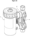
- the locking member 158 is rotated so that it moves along the male threaded section 160, away from the connecting handle member 156, until it is adjacent to the flat raised section 170 on the curved surface of the body of the separator device 10, as shown in Figure 18 .
- the Speedfit (RTM) connections 98 cannot be disengaged, since the collets 99 are inaccessible.
- the flat section 170 allows a tight fit against the locking member, whilst reducing the pressure by increasing the contact area, limiting the possibility of damage.
- the locking member 158 When the separator device needs to be removed from the pipe fitment, for example for cleaning, the locking member 158 is rotated so that it moves along the male threaded section 160, towards the connecting handle member 156 and away from the body of the separator device, as shown in Figure 17 . With the locking member 158 adjacent to the connecting handle member 156, the release tool 150 may be moved towards the body of the separator device 10, the discs 152 having bearing surfaces which engage with the collets 99 of the Speedfit (RTM) connectors 98 to release the connection.
- RTM Speedfit
- the release tool 150 includes raised areas 172 on outer edges of the bearing areas 152.
- the raised areas ensure that even force is provided on either side of the collets 99 in use.
- the release tool 150 is slightly curved and also may deform very slightly in use, the outer edges (furthest from the handle portion) bending away from the direction of the force applied to the handle portion.
- the raised areas 172 compensate for this, ensuring that the release tool pivots against the outer edges of the collets rather than the inner edges, so that the inner edge pushes into the collet when force is applied, rather than the outer edge moving away from the collet. In this way an even force is applied across opposing sides of the connectors and they release easily.
- the release tool allows for secure fitting and yet easy release of the separator device. Because the separator device may easily be completely removed from the pipework, additional flexibility is provided to the installer when the separator device is being initially located. The possibility of fast release means that it is not necessary to provide enough space above the separator device to unscrew the closure portion 16 and remove the removable insert 34 whilst the device is in situ. This allows installation, for example, between the bottom of a boiler and a countertop, where service and cleaning of the separator device would otherwise be impossible.
- a fitting jig is indicated at 180, connected to the pipe fitment 130.
- the fitting jig comprises a pair of apertures 182, 184 for receiving first and second pipe portions, and a connecting section 186 spacing the apertures 182, 184 a fixed distance apart.
- the axes of the apertures 182, 184 are parallel and have a depth of between 10mm and 30mm, preferably around 25mm.
- the apertures are a clearance fit on the first and second pipe portions, and the apertures slide on to the pipe portions, holding them accurately and firmly in line relative to one another.
- the fitting jig allows easy alignment of the first and second pipe portions 136, so that they are in the correct position for fitting of the separator device 10. If the separator device itself is used for this purpose, there is a danger of damage when torque is applied to the compression fittings 134. Use of the jig avoids this risk.
- the separator device 10 is easy to fit. Furthermore, the inlet and outlet can be interchanged, i.e. the flow direction can be changed, and the separator will operate effectively with flow in either direction. All of the separating chambers are able to cope with swirl in both directions within the housing. By providing three chambers with counter-rotating flow, filtration is achieved whilst the flow rate is substantially unaffected.
Landscapes
- Chemical & Material Sciences (AREA)
- Chemical Kinetics & Catalysis (AREA)
- Engineering & Computer Science (AREA)
- General Engineering & Computer Science (AREA)
- Mechanical Engineering (AREA)
- Water Supply & Treatment (AREA)
- Life Sciences & Earth Sciences (AREA)
- Hydrology & Water Resources (AREA)
- Health & Medical Sciences (AREA)
- Thermal Sciences (AREA)
- Physics & Mathematics (AREA)
- Combustion & Propulsion (AREA)
- Public Health (AREA)
- Environmental & Geological Engineering (AREA)
- Organic Chemistry (AREA)
- Analytical Chemistry (AREA)
- Filtration Of Liquid (AREA)
- Separating Particles In Gases By Inertia (AREA)
- Cyclones (AREA)
- Quick-Acting Or Multi-Walled Pipe Joints (AREA)
- Water Treatment By Electricity Or Magnetism (AREA)
- Centrifugal Separators (AREA)
- Lubrication Details And Ventilation Of Internal Combustion Engines (AREA)
- Steam Or Hot-Water Central Heating Systems (AREA)
- Separation Of Solids By Using Liquids Or Pneumatic Power (AREA)
Claims (11)
- Trennvorrichtung (10) zur Verwendung in einem hydronischen Heizsystem zum Entfernen von Teilchen aus einer Suspension in einer Flüssigkeit, wobei die Trennvorrichtung umfasst:Ein Gehäuse (12), das eine erste Kammer (19) und eine zweite Kammer (38) aufweist, wobei die zweite Kammer eine Trennkammer ist, Leitbleche, oder andere Behinderungsmittel (56, 62, 63, 68) in der zweiten Kammer vorgesehen sind, um den Fluss von Flüssigkeit innerhalb der zweiten Kammer zu verlangsamen, um kleine Feststoffteilchen von der Flüssigkeit zu trennen;Öffnungen (96) in dem Gehäuse, die einen Eintritt und Austritt von Flüssigkeit in die und aus der ersten Kammer erlauben, wobei der Fluss in der ersten Kammer zwischen dem Einlass und Auslass im Wesentlichen ungehindert ist;Mittel (100) zum Einrichten eines Flüssigkeitswirbels innerhalb der ersten Kammer;Öffnungen, die einen Fluss von Flüssigkeit aus der ersten Kammer zur zweiten Kammer und aus der zweiten Kammer zur ersten Kammer ermöglichen;Mittel (118, 66, 62) zum Leiten eines Flusses von Flüssigkeit in die, und innerhalb der zweiten Kammer, wobei die Mittel zum Leiten eines Flusses einen Flüssigkeitswirbel in der zweiten Kammer einrichten, die Mittel zum Leiten eines Flusses konfiguriert sind, um die Wirbelrichtung innerhalb der zweiten Kammer beim Eintritt in die zweite Kammer umzukehren, sodass der Wirbel in der zweiten Kammer in im Wesentlichen der umgekehrten Richtung zum Wirbel in der ersten Kammer verläuft;eine dritte Kammer (40), die in dem Gehäuse vorgesehen ist, wobei die dritte Kammer eine Trennkammer ist, die dritte Kammer für den Eintritt und Austritt von Flüssigkeit aus mindestens einer von der ersten Kammer und der zweiten Kammer geöffnet ist, und ein Mittel (90) zum Leiten eines Flusses von Flüssigkeit in der dritten Kammer vorgesehen ist; undeinen ummantelten (36) Magneten, der in der ersten Kammer angeordnet ist, welcher eine Trennung von magnetischen Teilchen in dem Wirbelfluss vorsieht.
- Trennvorrichtung (10) nach Anspruch 1, wobei das Mittel (90) zum Leiten eines Flusses von Flüssigkeit in der dritten Kammer (40) einen Wirbel von Flüssigkeit in der dritten Kammer einrichtet.
- Trennvorrichtung (10) nach Anspruch 1 oder Anspruch 2, wobei das Mittel (90) zum Leiten eines Flusses von Flüssigkeit in der dritten Kammer (40) die Flüssigkeit veranlasst, in derselben Richtung wie der Fluss in der zweiten Kammer (38) zu fließen.
- Trennvorrichtung (10) nach einem der vorstehenden Ansprüche, wobei die erste Kammer (19) zwischen der zweiten (38) und dritten Kammer (40) angeordnet ist.
- Trennvorrichtung (10) nach Anspruch 1, wobei das Mittel (90) zum Leiten eines Flusses von Flüssigkeit in der dritten Kammer (40) die Richtung des Flüssigkeitsflusses beim Eintreten in die dritte Kammer umkehrt.
- Trennvorrichtung (10) nach einem der vorstehenden Ansprüche, wobei die erste, zweite und dritte Kammer (19, 38, 40) eine einzige zentrale Achse gemeinsam nutzen.
- Trennvorrichtung (10) nach einem der vorstehenden Ansprüche, wobei die Mittel (118, 90) zum Leiten eines Flusses von Flüssigkeit innerhalb von mindestens einer von der zweiten Kammer (38) und, wo vorgesehen, der dritten Kammer (40) Öffnungen in der Kammer umfassen, die die Form von gekrümmten Schlitzen aufweisen.
- Trennvorrichtung (10) nach einem der vorstehenden Ansprüche, wobei die Mittel (118, 90) zum Leiten eines Flusses von Flüssigkeit innerhalb von mindestens einer von der zweiten Kammer (38) und, wo vorgesehen, der dritten Kammer (40) mindestens eine Flussleitung (90), die sich aus einer Wand (86) der Kammer angrenzend an die mindestens eine Öffnung in der Kammerwand erstreckt, umfassen.
- Trennvorrichtung (10) nach Anspruch 8, wobei die Flussleitung oder Flussleitungen (90) einen abgewinkelten Abweiser bilden, der über jede Öffnung überhängt.
- Trennvorrichtung (10) nach Anspruch 8 oder Anspruch 9, wobei sich die Flussleitung oder Flussleitungen (90) unterhalb der Öffnungswand in die Kammer erstrecken, in die der Fluss geleitet wird.
- Trennvorrichtung (10) nach einem der vorstehenden Ansprüche, wobei das Mittel (118) zum Leiten eines Flusses von Flüssigkeit innerhalb der zweiten Kammer (38) Flüsse von Flüssigkeit in entgegengesetzte Richtungen einrichtet, und wo die dritte Kammer (40) vorgesehen ist, das Mittel (90) zum Leiten eines Flusses von Flüssigkeit innerhalb der dritten Kammer Flüsse von Flüssigkeit in entgegengesetzte Richtungen einrichtet.
Priority Applications (1)
| Application Number | Priority Date | Filing Date | Title |
|---|---|---|---|
| EP15160050.9A EP2915570B1 (de) | 2012-05-21 | 2013-05-21 | Trennvorrichtung für ein Heizsystem |
Applications Claiming Priority (3)
| Application Number | Priority Date | Filing Date | Title |
|---|---|---|---|
| GB1208917.3A GB2491246B (en) | 2012-05-21 | 2012-05-21 | Separator device |
| GB1219752.1A GB2502384B (en) | 2012-05-21 | 2012-11-02 | Separator device |
| PCT/GB2013/051330 WO2013175201A2 (en) | 2012-05-21 | 2013-05-21 | Separator device |
Related Child Applications (2)
| Application Number | Title | Priority Date | Filing Date |
|---|---|---|---|
| EP15160050.9A Division EP2915570B1 (de) | 2012-05-21 | 2013-05-21 | Trennvorrichtung für ein Heizsystem |
| EP15160050.9A Division-Into EP2915570B1 (de) | 2012-05-21 | 2013-05-21 | Trennvorrichtung für ein Heizsystem |
Publications (3)
| Publication Number | Publication Date |
|---|---|
| EP2852449A2 EP2852449A2 (de) | 2015-04-01 |
| EP2852449C0 EP2852449C0 (de) | 2023-08-02 |
| EP2852449B1 true EP2852449B1 (de) | 2023-08-02 |
Family
ID=46546414
Family Applications (4)
| Application Number | Title | Priority Date | Filing Date |
|---|---|---|---|
| EP13725437.1A Active EP2852449B1 (de) | 2012-05-21 | 2013-05-21 | Trennvorrichtung |
| EP15177747.1A Active EP2977668B1 (de) | 2012-05-21 | 2013-05-21 | In-line-adapter zum anschluss eines filters an ein rohr |
| EP13725436.3A Active EP2852448B1 (de) | 2012-05-21 | 2013-05-21 | Separatorvorrichtung für ein heizungssystem |
| EP15160050.9A Active EP2915570B1 (de) | 2012-05-21 | 2013-05-21 | Trennvorrichtung für ein Heizsystem |
Family Applications After (3)
| Application Number | Title | Priority Date | Filing Date |
|---|---|---|---|
| EP15177747.1A Active EP2977668B1 (de) | 2012-05-21 | 2013-05-21 | In-line-adapter zum anschluss eines filters an ein rohr |
| EP13725436.3A Active EP2852448B1 (de) | 2012-05-21 | 2013-05-21 | Separatorvorrichtung für ein heizungssystem |
| EP15160050.9A Active EP2915570B1 (de) | 2012-05-21 | 2013-05-21 | Trennvorrichtung für ein Heizsystem |
Country Status (15)
| Country | Link |
|---|---|
| US (13) | US10029264B2 (de) |
| EP (4) | EP2852449B1 (de) |
| KR (2) | KR102148782B1 (de) |
| CN (3) | CN104470610B (de) |
| AU (3) | AU2013264997B2 (de) |
| CA (3) | CA2873951C (de) |
| DK (1) | DK2977668T3 (de) |
| ES (1) | ES2618008T3 (de) |
| GB (2) | GB2491246B (de) |
| HU (4) | HUE058173T2 (de) |
| NZ (4) | NZ702608A (de) |
| PL (3) | PL2852449T3 (de) |
| PT (1) | PT2977668T (de) |
| RU (4) | RU2633574C2 (de) |
| WO (2) | WO2013175201A2 (de) |
Families Citing this family (93)
| Publication number | Priority date | Publication date | Assignee | Title |
|---|---|---|---|---|
| GB2504259A (en) * | 2012-05-15 | 2014-01-29 | Scalemaster Ltd | Magnetic sludge filter |
| GB2504919A (en) * | 2012-05-15 | 2014-02-19 | Scalemaster Ltd | Magnetic sludge filter |
| GB2491246B (en) | 2012-05-21 | 2013-05-15 | Adey Holdings 2008 Ltd | Separator device |
| GB2502280A (en) | 2012-05-21 | 2013-11-27 | Adey Holdings 2008 Ltd | Separator device |
| GB2520680B (en) * | 2013-11-27 | 2018-07-25 | Bisset James | A central heating system device |
| GB2524056B (en) | 2014-03-13 | 2016-11-02 | Adey Holdings 2008 Ltd | Connection assembly |
| US9885196B2 (en) | 2015-01-26 | 2018-02-06 | Hayward Industries, Inc. | Pool cleaner power coupling |
| EP3508275B1 (de) | 2015-01-26 | 2023-04-26 | Hayward Industries, Inc. | Schwimmbadreiniger mit hydrozyklonischem partikelabscheider und walzenantriebssystem |
| GB2535500B (en) | 2015-02-19 | 2017-06-21 | Adey Holdings 2008 Ltd | Magnetic filter for a central heating system |
| WO2016199035A1 (en) * | 2015-06-10 | 2016-12-15 | Stucchi S.P.A. | Anti-unscrewing quick coupling fitting |
| CN105080733B (zh) * | 2015-09-16 | 2017-08-25 | 重庆市九瑞粉末冶金有限责任公司 | 离心式磁力铁粉筛分装置 |
| AU365774S (en) * | 2015-11-16 | 2015-12-11 | Reliance Worldwide Corp Aust Pty Ltd | Valve with angled flange |
| CA169352S (en) | 2016-01-13 | 2018-01-25 | Adey Holdings 2008 Ltd | Filter for a central heating system |
| CA169351S (en) | 2016-01-13 | 2018-01-25 | Adey Holdings 2008 Ltd | Filter for a central heating system |
| GB201601488D0 (en) * | 2016-01-27 | 2016-03-09 | Primary Water Treat S Ltd | Improvements in and relating to heating and cooling systems |
| US9884778B2 (en) * | 2016-02-19 | 2018-02-06 | Meiju SHAO | Filter with magnet and protective bushing |
| CN109154472A (zh) * | 2016-02-19 | 2019-01-04 | 阿尔伯特·马迪凯恩 | 用于处理废物以形成可用的产品的系统及其方法 |
| US10919249B2 (en) | 2016-02-19 | 2021-02-16 | Albert Mardikian | Apparatus for pressing and dehydrating of waste |
| USD803985S1 (en) * | 2016-03-04 | 2017-11-28 | Eastern Foundry & Fittings Inc. | Ball valve with integral elbow |
| GB2549496B (en) | 2016-04-19 | 2020-12-30 | Adey Holdings 2008 Ltd | Monitoring magnetite buildup in a magnetic filter |
| CA3027198C (en) * | 2016-06-09 | 2022-07-26 | Amtrol, Inc. | Air and particle separators |
| ITUA20164363A1 (it) * | 2016-06-14 | 2017-12-14 | Giacomini Spa | Gruppo filtrante per impianti di riscaldamento e simili |
| KR101696426B1 (ko) * | 2016-06-28 | 2017-01-16 | 주식회사 나누텍 | 비데의 순간 온수 가열장치 |
| USD802098S1 (en) * | 2016-10-21 | 2017-11-07 | Watts Regulator Co. | Faucet inner housing |
| USD867568S1 (en) * | 2016-12-09 | 2019-11-19 | Briggs & Stratton Corporation | Air filter |
| USD828497S1 (en) * | 2017-02-07 | 2018-09-11 | Leonard Valve Company | Controller box dashboard |
| USD818562S1 (en) * | 2017-02-09 | 2018-05-22 | Eastern Foundry & Fittings Inc. | Manifold U-valve |
| USD822173S1 (en) * | 2017-02-09 | 2018-07-03 | Eastern Foundry & Fittings Inc. | Tee-shaped ball valve |
| USD834150S1 (en) * | 2017-02-09 | 2018-11-20 | Eastern Foundry & Fittings Inc. | Ball valve |
| USD864353S1 (en) | 2017-03-10 | 2019-10-22 | Neoperl Gmbh | Fluid distribution equipment |
| IT201700026845A1 (it) * | 2017-03-10 | 2018-09-10 | Mut Mecc Tovo Spa | Separatore di impurita’ dai fluidi di tipo perfezionato |
| CN106989244A (zh) * | 2017-04-07 | 2017-07-28 | 周肇梅 | 一种水利工程用的管道 |
| US10156083B2 (en) | 2017-05-11 | 2018-12-18 | Hayward Industries, Inc. | Pool cleaner power coupling |
| US9896858B1 (en) | 2017-05-11 | 2018-02-20 | Hayward Industries, Inc. | Hydrocyclonic pool cleaner |
| US9885194B1 (en) | 2017-05-11 | 2018-02-06 | Hayward Industries, Inc. | Pool cleaner impeller subassembly |
| JP2019027744A (ja) * | 2017-08-03 | 2019-02-21 | パナソニックIpマネジメント株式会社 | ヒートポンプ温水暖房機 |
| CA179927S (en) * | 2017-09-08 | 2019-02-13 | Adey Holdings 2008 Ltd | Filter for a central heating system |
| USD866713S1 (en) | 2017-09-13 | 2019-11-12 | Neoperl Gmbh | Fluid distributor |
| DK3795910T3 (da) | 2017-10-02 | 2023-09-18 | Adey Holdings 2008 Ltd | Måling af magnetisk affaldsophobning i et magnetfilter |
| USD876600S1 (en) | 2018-01-12 | 2020-02-25 | Briggs & Stratton Corporation | Air filter |
| USD907172S1 (en) * | 2018-04-16 | 2021-01-05 | Amiad Water System Ltd. | Filtration system |
| USD909531S1 (en) * | 2018-04-16 | 2021-02-02 | Amiad Water System Ltd. | Filtration system |
| GB2573117B (en) | 2018-04-24 | 2021-02-17 | Adey Holdings 2008 Ltd | Magnetic filter |
| USD886236S1 (en) | 2018-05-16 | 2020-06-02 | Bradley Fixtures Corporation | Housing for multiple valves |
| EP3794258A1 (de) | 2018-05-16 | 2021-03-24 | Bradley Fixtures Corporation | Gehäuse für mehrfachventile |
| SE542281C2 (en) * | 2018-07-12 | 2020-03-31 | Atlas Copco Ind Technique Ab | Power tool attachment part |
| CN110360457B (zh) * | 2018-09-05 | 2023-12-19 | 上海北昂医药科技股份有限公司 | 晶体颗粒处理装置 |
| JP1647724S (de) * | 2018-10-02 | 2019-12-09 | ||
| USD957587S1 (en) * | 2019-01-11 | 2022-07-12 | Adey Holdings (2008) Limited | Magnetic filter without valves |
| USD957592S1 (en) * | 2019-01-11 | 2022-07-12 | Adey Holdings (2008) Limited | Valve for magnetic filter |
| USD950009S1 (en) * | 2019-01-24 | 2022-04-26 | Rohm And Haas Electronic Materials Singapore Pte. Ltd | Membrane filtration module |
| USD944931S1 (en) | 2019-04-16 | 2022-03-01 | Reliance Worldwide Corporation | Valve assembly |
| USD964509S1 (en) * | 2019-05-30 | 2022-09-20 | Adey Holdings (2008) Limited | Magnetic filter and connection assembly |
| USD964508S1 (en) * | 2019-05-30 | 2022-09-20 | Adey Holdings (2008) Limited | Canister for magnetic filter |
| KR20210020611A (ko) | 2019-08-16 | 2021-02-24 | 삼성전자주식회사 | 전자 장치 및 전자 장치에서 서비스 제공 방법 |
| CN111088059B (zh) * | 2019-12-12 | 2021-12-14 | 济宁长胜新材料股份有限公司 | 一种焦化加热炉弯管缓冲装置 |
| USD935593S1 (en) * | 2020-01-14 | 2021-11-09 | Scentair Technologies, Llc | Scent diffuser |
| US11241644B2 (en) * | 2020-04-13 | 2022-02-08 | Pall Corporation | Adapter for filter device and method of use |
| KR20210132921A (ko) * | 2020-04-28 | 2021-11-05 | 주식회사 아모그린텍 | 중력식 정수장치용 필터모듈 및 이를 포함하는 중력식 정수장치 |
| CN111841091B (zh) * | 2020-06-16 | 2021-12-07 | 中交第三公路工程局有限公司 | 排泥设施 |
| USD1002793S1 (en) * | 2020-07-01 | 2023-10-24 | Evoqua Water Technologies Llc | Regenerative media filter |
| US11904263B2 (en) | 2020-07-10 | 2024-02-20 | Entegris, Inc. | Connection assembly and filter assembly |
| US11547959B2 (en) | 2020-07-17 | 2023-01-10 | The Metraflex Company | Magnetic baffle insert for use with a basket strainer |
| US11253870B2 (en) | 2020-07-17 | 2022-02-22 | The Metraflex Company | Magnetic baffle insert for use with a basket strainer |
| USD990627S1 (en) * | 2020-09-03 | 2023-06-27 | Lih Yann Industrial Co., Ltd. | Water tank testing device |
| RU206328U1 (ru) * | 2021-01-29 | 2021-09-06 | Болтенков Евгений Владимирович | Магнитогравитационный сепаратор |
| RU2771346C1 (ru) * | 2021-01-29 | 2022-04-29 | Болтенков Евгений Владимирович | Магнито-гравитационный сепаратор |
| RU207906U1 (ru) * | 2021-04-06 | 2021-11-23 | Сергей Петрович Батуев | Фильтр-грязевик инерционно-гравитационный с тангенциальным подводом воды |
| US11707705B2 (en) | 2021-05-05 | 2023-07-25 | Nibco Inc. | Multi-function hydraulic separator |
| US12312261B2 (en) | 2021-05-11 | 2025-05-27 | Nibco Inc. | Magnetic water filter assembly |
| US11786913B2 (en) * | 2021-05-14 | 2023-10-17 | Saudi Arabian Oil Company | Y-shaped magnetic filtration device |
| USD1007641S1 (en) | 2021-07-14 | 2023-12-12 | Evoqua Water Technologies Llc | Regenerative media filter with view window |
| USD1077993S1 (en) * | 2021-08-27 | 2025-06-03 | Botrista, Inc. | Dual-mode fluid connector |
| USD1021048S1 (en) * | 2021-11-30 | 2024-04-02 | Foshan Samyoo Electronic Co., Ltd. | Booster fan |
| USD1010793S1 (en) * | 2021-12-10 | 2024-01-09 | Lixin Zeng | Fan |
| USD989244S1 (en) * | 2021-12-23 | 2023-06-13 | Ngi A/S | Joint for pipes |
| USD1006976S1 (en) * | 2021-12-27 | 2023-12-05 | Jiangmen Keye Electric Appliances Manufacturing Co., Ltd | Tripod table fan |
| USD1031968S1 (en) * | 2021-12-31 | 2024-06-18 | Suzhou Beiang Smart Technology Co. Ltd. | Fan |
| USD1001992S1 (en) * | 2022-01-20 | 2023-10-17 | Shenzhen Chinaunion Technology Co., Ltd. | Outdoor fan |
| USD1010093S1 (en) * | 2022-01-24 | 2024-01-02 | Weibin XIE | Portable desktop USB fan |
| USD1004763S1 (en) * | 2022-01-24 | 2023-11-14 | Shenzhen Maxlink Century Technology Co., Ltd | Vehicle-mounted fan |
| USD1004070S1 (en) * | 2022-01-27 | 2023-11-07 | Hoteck Inc. | Portable fan |
| USD1033620S1 (en) * | 2022-03-04 | 2024-07-02 | Delta Electronics, Inc. | Fan |
| EP4522303A1 (de) * | 2022-05-12 | 2025-03-19 | Caleffi S.p.A. | Vorrichtung zur trennung von gas aus einer vektorflüssigkeit in einem kreislauf eines thermischen systems |
| USD1025289S1 (en) * | 2022-11-18 | 2024-04-30 | Fujian Aidi Electric Co., Ltd. | Raw water strainer |
| CN115854408B (zh) * | 2023-03-01 | 2023-05-02 | 四川蜀旺新能源股份有限公司 | 一种用于热电联供的电热辅助系统 |
| USD1068032S1 (en) * | 2023-07-20 | 2025-03-25 | Ningbo Yod Import & Export Co., Ltd. | Fluid distribution valve |
| USD1007665S1 (en) * | 2023-07-20 | 2023-12-12 | Xiongjian Chen | Fan |
| USD1003418S1 (en) * | 2023-07-30 | 2023-10-31 | Mambate US Inc. | Camping fan |
| USD1095209S1 (en) * | 2024-03-01 | 2025-09-30 | Clean Water Guys of Arizona, LLC | Disconnect tool for removing quick connect plumbing fittings |
| GB2640902A (en) * | 2024-05-09 | 2025-11-12 | Eclipse Magnetics Ltd | Helical Flow Magnetic Filtration Device |
| USD1112640S1 (en) * | 2024-05-29 | 2026-02-10 | Gilbert Rodriquez | Gas manifold system |
| CN119455508B (zh) * | 2025-01-13 | 2025-05-02 | 福力达智控科技(浙江)有限公司 | 凝集过滤设备滤芯容器 |
Citations (5)
| Publication number | Priority date | Publication date | Assignee | Title |
|---|---|---|---|---|
| FR2693662A1 (fr) * | 1992-07-17 | 1994-01-21 | Valdenaire Bruno | Dispositif de filtrage et de traitement d'eau pour prévenir l'incrustation de tartre. |
| US6241881B1 (en) * | 1997-11-21 | 2001-06-05 | University Of South Australia | Pollution separator and filtration apparatus |
| US20050184007A1 (en) * | 2004-02-20 | 2005-08-25 | Allard Douglas P. | Storm water treatment apparatus employing dual vortex separators |
| US20070012608A1 (en) * | 2005-07-18 | 2007-01-18 | Ohio University | Storm water runoff treatment system |
| GB2469145A (en) * | 2009-02-25 | 2010-10-06 | Johal Prakash Singh | Magnetic filter |
Family Cites Families (123)
| Publication number | Priority date | Publication date | Assignee | Title |
|---|---|---|---|---|
| BE546074A (de) | ||||
| GB233727A (en) * | 1924-05-10 | 1925-12-03 | William Patrick Day | Improvements in and relating to track substructures for railroads, particularly street railways |
| GB274729A (en) | 1927-01-19 | 1927-07-28 | James Lever Rushton | Improvements in or relating to fluid tight couplings or unions for pipes or tubes |
| US2002070A (en) | 1931-01-26 | 1935-05-21 | Celanese Corp | Knitting machine |
| US2105954A (en) * | 1936-08-01 | 1938-01-18 | Walter H Rippe | Pipe aligning tool |
| US2577034A (en) * | 1949-04-16 | 1951-12-04 | John H Quinlan | Doorway gate |
| US2737204A (en) * | 1952-09-16 | 1956-03-06 | Bonte Fred E La | Conduit structure |
| GB737822A (en) * | 1953-05-11 | 1955-10-05 | Farm Production Engineers Inc | Method of separating dispersed matter from fluid masses |
| GB855928A (en) * | 1957-08-02 | 1960-12-14 | Thoma Jean Ulrich | Magnetic separators |
| US3072260A (en) * | 1958-07-02 | 1963-01-08 | Acf Ind Inc | Fuel filter |
| FR1362537A (fr) | 1963-04-05 | 1964-06-05 | Mécanique jacquard à pas ouvert avec aiguilles de crochets à double action positive | |
| US3339740A (en) * | 1964-04-30 | 1967-09-05 | Starzyk Boris | Centrifugal-type oil reconditioner having deflecting and settling partitions |
| US3412854A (en) | 1966-03-21 | 1968-11-26 | Kimberly Clark Co | Apparatus for separation of magnetizable material from stock suspensions |
| US3356391A (en) | 1967-01-10 | 1967-12-05 | Richard L Bailey | Pipe or tube coupling device |
| SE323651B (de) * | 1969-02-13 | 1970-05-11 | Celleco Ab | |
| SE357309B (de) | 1969-03-21 | 1973-06-25 | Celleco Ab | |
| US3669274A (en) * | 1969-12-29 | 1972-06-13 | George M Happ | Magnetic structure for treating liquids containing calcareous matter |
| CH539231A (de) * | 1972-02-17 | 1973-07-15 | Walter Hussauf Sanitaere Anlag | Anschlussvorrichtung für die Wandmontage einer Kalt- und Warmwasserbatterie |
| JPS5721365B2 (de) * | 1972-05-26 | 1982-05-07 | ||
| US3916947A (en) * | 1974-03-13 | 1975-11-04 | Aeroquip Corp | Refrigeration system valved fitting |
| GB1520742A (en) * | 1975-07-30 | 1978-08-09 | Guest J D | Couplings for tubes |
| SU519570A1 (ru) * | 1975-02-10 | 1976-06-30 | Государственный Проектно-Конструкторский И Экспериментальный Институт Угольноно Машиностроения "Гипроуглемаш" | Быстроразьемное соединение |
| US4090956A (en) * | 1976-09-02 | 1978-05-23 | Wilmot Engineering Co. | Hydrocyclone |
| SU940863A1 (ru) | 1979-06-13 | 1982-07-07 | Дзержинский Филиал Всесоюзного Научно-Исследовательского И Конструкторского Института Химического Машиностроения | Гидроциклон дл разделени концентрированных суспензий |
| US4585553A (en) * | 1982-11-24 | 1986-04-29 | Dai Nippon Insatsu Kabushiki Kaisha | Apparatus for the removal of solid particles from printing ink or other liquids |
| FI65920C (fi) * | 1983-01-21 | 1984-08-10 | Nobar Ky | Foerfarande och anordning foer separering av ett medium i olika komponenter |
| US4544483A (en) * | 1984-03-12 | 1985-10-01 | Puratrol, Inc. | Dynamic, reverse-flow oil purifier device |
| AT380321B (de) | 1984-05-17 | 1986-05-12 | Voest Alpine Ag | Rohrverbindung zum verbinden von zwei mit gewinden versehenen rohrenden |
| US4881573A (en) | 1989-01-31 | 1989-11-21 | Deere & Company | Female hydraulic coupler with push-connect and lever disconnect |
| US5028318A (en) * | 1989-04-19 | 1991-07-02 | Aeroquip Corporation | Cyclonic system for separating debris particles from fluids |
| GB2233727B (en) | 1989-07-13 | 1993-02-10 | Pall Corp | Filter assemblies and couplings |
| SU1682714A1 (ru) * | 1989-11-03 | 1991-10-07 | Центральный Научно-Исследовательский И Проектно-Экспериментальный Институт Инженерного Оборудования | Гр зевик |
| DE4037308C1 (en) * | 1990-11-23 | 1992-04-16 | Rasmussen Gmbh, 6457 Maintal, De | Multiple pipeline coupling with interconnected tubular members - which are linked by flexible holder in releasable manner |
| US5118024A (en) * | 1991-08-01 | 1992-06-02 | Mcclure Gary W | Remote pipe fitting tool |
| US5333467A (en) * | 1991-11-22 | 1994-08-02 | Uniweld Products, Inc. | Apparatus and method of preventing fluid escape from a conduit |
| US5203891A (en) * | 1992-04-03 | 1993-04-20 | The United States Of America As Represented By The Secretary Of The Navy | Gas/liquid separator |
| US5257525A (en) * | 1992-06-24 | 1993-11-02 | Atco Products, Inc. | Portable slim-line hose fitting crimper |
| JPH0796833B2 (ja) * | 1992-09-25 | 1995-10-18 | 政太郎 佐藤 | 管材連結用クランプ金具組立体 |
| US5392672A (en) * | 1993-03-09 | 1995-02-28 | Larry R. Larson | Ratchet wrench |
| DE4310795C1 (de) * | 1993-04-02 | 1994-07-14 | Rasmussen Gmbh | Steckkupplung |
| FR2713305B1 (fr) * | 1993-11-29 | 1996-02-09 | Valeo Thermique Habitacle | Dispositif de raccord rapide pour tubulures d'échangeur de chaleur. |
| CN2176836Y (zh) | 1994-01-31 | 1994-09-14 | 张景聪 | 强磁吸铁器 |
| DE4404661A1 (de) | 1994-02-14 | 1995-08-17 | Stiftung Inst Fuer Werkstoffte | Anordnung zum Abscheiden in einem Zyklon |
| KR100386823B1 (ko) * | 1995-12-06 | 2003-08-27 | 다겐 텟구스 가부시키가이샤 | 여과지를 사용하지 않는 영구자석에 의한 오일필터 |
| JPH09183068A (ja) * | 1996-01-04 | 1997-07-15 | Duskin Co Ltd | フラッシュバルブの固定治具 |
| ATE208669T1 (de) * | 1996-08-09 | 2001-11-15 | Uwe Vieregge | Vorrichtung und verfahren zum verbinden eines ersten rohres mit einem rohrförmigen element |
| USD420099S (en) * | 1997-07-31 | 2000-02-01 | Nordson Corporation | Fitting for a valve switch |
| USD400970S (en) * | 1997-09-29 | 1998-11-10 | Bestwill Corporation | One-quarter turn straight ball shutoff valve |
| GB9803539D0 (en) | 1998-02-19 | 1998-04-15 | Arnold Adrian C | Cleaning apparatus |
| US7048007B2 (en) * | 1998-03-05 | 2006-05-23 | Swagelok Company | Modular surface mount manifold assemblies |
| FR2778178B1 (fr) | 1998-04-30 | 2003-09-26 | Cofex | Filtre magnetique pour circuits d'eau |
| CN2329419Y (zh) | 1998-06-25 | 1999-07-21 | 周新昌 | 自动油水分离器 |
| EP1150762B1 (de) | 1999-02-02 | 2002-12-11 | N.V. Bekaert S.A. | Bandgewickelte filterpatrone |
| USD425965S (en) * | 1999-04-02 | 2000-05-30 | Ecolab, Inc. | Dispensing system probe |
| US6143171A (en) * | 1999-04-07 | 2000-11-07 | Van Aarsen; Freda Martha | Magnetic device for treatment of fluids |
| GB2349685A (en) | 1999-04-21 | 2000-11-08 | H P Rota Valve Systems Ltd | Radiator valve with rotational seal that enables rotation of radiator away from wall |
| JP3223450B2 (ja) * | 1999-06-07 | 2001-10-29 | モリオキ産業株式会社 | 超高磁気流体処理装置 |
| US6155140A (en) * | 1999-09-09 | 2000-12-05 | Tsai; Tzen Chang | Ratchet wrench |
| US6167604B1 (en) * | 1999-10-18 | 2001-01-02 | Dennis E. Del Bono | Curb valve replacement and installation tool |
| USD454614S1 (en) * | 2000-08-31 | 2002-03-19 | Hozelock Limited | Water treatment unit |
| RU2175954C1 (ru) | 2000-10-05 | 2001-11-20 | Научно-Производственная Фирма "Продэкология" | Магнитный инерционно-гравитационный фильтрующий осветлитель |
| JP2002172540A (ja) * | 2000-12-07 | 2002-06-18 | Nok Corp | 水溶性クーラント液再生装置 |
| US6578876B2 (en) | 2000-12-12 | 2003-06-17 | Good Turns, Llc | Plumbing connection and disconnection system and method |
| CN2486820Y (zh) * | 2001-06-04 | 2002-04-17 | 梁启良 | 管道过滤器 |
| RU2205701C1 (ru) | 2001-12-27 | 2003-06-10 | Сальников Георгий Иванович | Магнитный сепаратор |
| DE10202790A1 (de) | 2002-01-25 | 2003-08-14 | Simag Blazenka | Rohrpresskupplung |
| TWI269665B (en) * | 2002-02-21 | 2007-01-01 | Roger P Reid | Quick change filter and bracket system with key system and universal key option |
| US6740235B2 (en) * | 2002-03-04 | 2004-05-25 | Culligan International Company | Swivelling filter head assembly |
| US6708717B1 (en) | 2002-05-10 | 2004-03-23 | Coogle Technology, L.L.C. | Flushing system for air conditioning drainage pipes |
| USD470222S1 (en) * | 2002-06-13 | 2003-02-11 | Sloan Valve Company | Toilet room flush valve |
| USD486204S1 (en) * | 2002-07-01 | 2004-02-03 | B&K Industries | Ball valve body |
| FR2844333B1 (fr) * | 2002-09-11 | 2004-11-26 | Bosch Gmbh Robert | Dispositif de raccordement rapide d'organes male et femelle et ensemble formant reservoir pour liquide de frein de ce dispositif |
| USD478650S1 (en) * | 2002-10-15 | 2003-08-19 | Hung-Lin Lai | Switch valve |
| GB2402894B (en) * | 2003-05-29 | 2007-11-07 | Chris Adey | Separator device |
| TWI285562B (en) * | 2003-10-10 | 2007-08-21 | Tama Tlo Corp | Cyclone type centrifugal separating apparatus |
| USD498821S1 (en) * | 2004-01-20 | 2004-11-23 | Sloan Valve Company | Actuator housing for a flush valve |
| USD541379S1 (en) * | 2004-01-20 | 2007-04-24 | Sloan Valve Company | Flush valve control stop |
| EP1732661A4 (de) | 2004-02-03 | 2007-05-30 | Zohar Waterworks Llc | Filterpatrone und verteiler für ein wasserreinigungssystem |
| USD502762S1 (en) * | 2004-02-18 | 2005-03-08 | Duane D. Kriegshauser | Multiple outlet valve for measured gauged flow |
| USD519188S1 (en) * | 2004-07-13 | 2006-04-18 | Hayco Manufacturing Limited | Valve unit |
| USD544321S1 (en) * | 2005-01-14 | 2007-06-12 | Impex Patrick Wyss | Tap wrench |
| US7469880B2 (en) * | 2005-03-16 | 2008-12-30 | Green Ronald D | Quick connect feature for a fluid connection |
| DE102006021800B3 (de) * | 2006-05-08 | 2008-02-07 | Hans Sasserath & Co. Kg | Armaturenbausatz zum Be- oder Nachfüllen von Heizungssystemen |
| US20080000820A1 (en) * | 2006-06-30 | 2008-01-03 | Mitchell Alan J | Water Filter Cartridge and Valve with Autobypass Feature |
| JP4150412B1 (ja) * | 2007-04-27 | 2008-09-17 | 東光株式会社 | 活性水用磁場形成具及びそれを用いた流体処理装置 |
| CN101293337A (zh) * | 2007-04-29 | 2008-10-29 | 上海诺玛液压系统有限公司 | 用于电液伺服阀中接受器与先导阀体的装配夹具及其方法 |
| GB2450335A (en) | 2007-06-19 | 2008-12-24 | Fluid Conditioning Systems Ltd | A separator device |
| DE202007013057U1 (de) * | 2007-09-18 | 2007-12-20 | Chen, Tsai-Ching, Fu Hsing | Schraubenschlüssel mit einem umschaltbaren Zahnrad |
| DE102007049626A1 (de) | 2007-10-12 | 2009-04-16 | Jenoptik Laser, Optik, Systeme Gmbh | Verfahren und Vorrichtung zur Beleuchtung einer optischen Abbildungseinrichtung |
| DE102007049206A1 (de) * | 2007-10-13 | 2009-04-16 | Lerner, A. | Vorrichtung zur Aufbereitung eines Fluids unter Verwendung von Permanentmagneten |
| KR100985098B1 (ko) | 2008-05-19 | 2010-10-05 | 주식회사 경동도시가스 | 가스정압기의 철가루 제거장치 |
| US8109295B2 (en) * | 2008-10-24 | 2012-02-07 | Tyco Valves & Controls Lp | Manifold assembly |
| GB2465547B (en) * | 2008-11-18 | 2010-10-13 | Chen-Tsung Chen | Open-ended ratchet wrench |
| GB2467136B (en) * | 2009-01-22 | 2013-08-28 | Chih-Ching Hsieh | Wrench with a rotatable head |
| KR101703334B1 (ko) * | 2009-05-27 | 2017-02-06 | 파커-한니핀 코포레이션 | 필터의 프라이밍 방법 |
| US8961792B2 (en) * | 2010-06-03 | 2015-02-24 | Titan Flow Control, Inc. | Duplex strainer apparatuses and methods |
| CN101967018A (zh) * | 2010-09-14 | 2011-02-09 | 蒯琦 | 高效磁化叶轮式磁化水处理器 |
| US8999158B2 (en) | 2010-09-16 | 2015-04-07 | Wallace Taylor Irvin | In-line fuel conditioner |
| US8858794B2 (en) | 2010-09-22 | 2014-10-14 | Wayne Lappeman | Sediment collecting container |
| CN201840931U (zh) * | 2010-09-28 | 2011-05-25 | 烟台杞杨机械有限公司 | 磁性过滤器 |
| DE202010008759U1 (de) * | 2010-10-08 | 2012-01-13 | Hans Sasserath & Co. Kg | Mehrteilige Armaturenanordnungen |
| DE102010043932A1 (de) | 2010-11-15 | 2012-05-16 | BSH Bosch und Siemens Hausgeräte GmbH | Verbindungssystem zur Installation eines wasserführenden Gerätes |
| GB2508257B (en) * | 2010-12-01 | 2014-07-23 | Adey Holdings 2008 Ltd | Water and dirt separator |
| GB2486173B (en) | 2010-12-01 | 2017-02-01 | Adey Holdings 2008 Ltd | Separator |
| USD654558S1 (en) * | 2011-01-30 | 2012-02-21 | Shenzhen Lenyo Aquatics Co., Ltd. | UV stabilizer |
| USD678981S1 (en) * | 2011-05-03 | 2013-03-26 | Brasscraft Manufacturing Company | Valve |
| CN202061466U (zh) * | 2011-05-10 | 2011-12-07 | 魏成和 | 磁性过滤器 |
| KR101977022B1 (ko) * | 2011-06-30 | 2019-05-10 | 웅진코웨이 주식회사 | 필터 헤드와 이를 포함하는 필터 어셈블리, 수처리 장치 |
| RU115036U1 (ru) * | 2011-07-21 | 2012-04-20 | Павел Эдуардович Мельников | Трубопроводный фильтр |
| USD675705S1 (en) * | 2011-09-05 | 2013-02-05 | I.D. Electroquimica, S.L. | Water treatment apparatus |
| CA147251S (en) * | 2012-03-07 | 2013-05-15 | Mitsubishi Rayon Co | Degassing aeration membrane module |
| US8807525B2 (en) * | 2012-05-03 | 2014-08-19 | Sun-Wounder Industrial Co., Ltd | Quick-release coupling |
| GB2502280A (en) * | 2012-05-21 | 2013-11-27 | Adey Holdings 2008 Ltd | Separator device |
| GB2491246B (en) * | 2012-05-21 | 2013-05-15 | Adey Holdings 2008 Ltd | Separator device |
| USD710969S1 (en) * | 2012-12-04 | 2014-08-12 | Whirlpool Corporation | Water filter suspension apparatus |
| GB2524056B (en) * | 2014-03-13 | 2016-11-02 | Adey Holdings 2008 Ltd | Connection assembly |
| USD720048S1 (en) * | 2014-08-26 | 2014-12-23 | Craig V. Winborn | Multi-port valve |
| AU358035S (en) * | 2014-09-22 | 2014-10-03 | Reliance Worldwide Corp Aust Pty Ltd | Valve |
| US20160153571A1 (en) * | 2014-12-02 | 2016-06-02 | Vir Valvoindustria Ing. Rizzio S.P.A. | Bypass valve |
| JP1535277S (de) * | 2015-03-20 | 2015-10-19 | ||
| USD755592S1 (en) * | 2015-03-25 | 2016-05-10 | Kevin Bullard | Radiator wrench |
| USD796281S1 (en) * | 2016-01-07 | 2017-09-05 | Adey Holdings (2008) Limited | Opening tool for a filter |
| USD795999S1 (en) * | 2016-01-07 | 2017-08-29 | Adey Holdings (2008) Limited | Water filter |
-
2012
- 2012-05-21 GB GB1208917.3A patent/GB2491246B/en active Active
- 2012-11-02 GB GB1219752.1A patent/GB2502384B/en active Active
-
2013
- 2013-05-21 EP EP13725437.1A patent/EP2852449B1/de active Active
- 2013-05-21 DK DK15177747.1T patent/DK2977668T3/da active
- 2013-05-21 EP EP15177747.1A patent/EP2977668B1/de active Active
- 2013-05-21 PL PL13725437.1T patent/PL2852449T3/pl unknown
- 2013-05-21 HU HUE15177747A patent/HUE058173T2/hu unknown
- 2013-05-21 WO PCT/GB2013/051330 patent/WO2013175201A2/en not_active Ceased
- 2013-05-21 NZ NZ702608A patent/NZ702608A/en unknown
- 2013-05-21 EP EP13725436.3A patent/EP2852448B1/de active Active
- 2013-05-21 RU RU2014151748A patent/RU2633574C2/ru active
- 2013-05-21 CA CA2873951A patent/CA2873951C/en active Active
- 2013-05-21 PT PT151777471T patent/PT2977668T/pt unknown
- 2013-05-21 CA CA3049045A patent/CA3049045C/en active Active
- 2013-05-21 KR KR1020147035611A patent/KR102148782B1/ko not_active Expired - Fee Related
- 2013-05-21 CA CA2873950A patent/CA2873950C/en active Active
- 2013-05-21 US US14/402,955 patent/US10029264B2/en active Active
- 2013-05-21 AU AU2013264997A patent/AU2013264997B2/en active Active
- 2013-05-21 HU HUE15160050A patent/HUE045045T2/hu unknown
- 2013-05-21 CN CN201380038483.8A patent/CN104470610B/zh not_active Expired - Fee Related
- 2013-05-21 US US14/402,968 patent/US9873130B2/en active Active
- 2013-05-21 KR KR1020147035612A patent/KR102056487B1/ko not_active Expired - Fee Related
- 2013-05-21 CN CN201610109130.8A patent/CN105749589B/zh active Active
- 2013-05-21 RU RU2014151738A patent/RU2635616C2/ru active
- 2013-05-21 EP EP15160050.9A patent/EP2915570B1/de active Active
- 2013-05-21 PL PL15177747.1T patent/PL2977668T3/pl unknown
- 2013-05-21 NZ NZ713358A patent/NZ713358A/en unknown
- 2013-05-21 CN CN201380038488.0A patent/CN104470611B/zh active Active
- 2013-05-21 RU RU2017120024A patent/RU2729672C2/ru active
- 2013-05-21 HU HUE13725436A patent/HUE045047T2/hu unknown
- 2013-05-21 WO PCT/GB2013/051329 patent/WO2013175200A1/en not_active Ceased
- 2013-05-21 AU AU2013264996A patent/AU2013264996B2/en not_active Ceased
- 2013-05-21 NZ NZ702605A patent/NZ702605A/en not_active IP Right Cessation
- 2013-11-04 HU HUE13786743A patent/HUE032577T2/en unknown
- 2013-11-04 ES ES13786743.8T patent/ES2618008T3/es active Active
- 2013-11-04 PL PL13786743T patent/PL2914359T3/pl unknown
- 2013-11-04 RU RU2015126490A patent/RU2671744C9/ru active
- 2013-11-04 NZ NZ707306A patent/NZ707306A/en unknown
- 2013-11-04 US US14/439,059 patent/US9931647B2/en active Active
-
2016
- 2016-04-06 US US29/560,402 patent/USD792942S1/en active Active
- 2016-04-06 US US29/560,419 patent/USD812724S1/en active Active
- 2016-04-06 US US29/560,417 patent/USD796633S1/en active Active
- 2016-04-06 US US29/560,408 patent/USD793522S1/en active Active
- 2016-04-06 US US29/560,415 patent/USD823431S1/en active Active
- 2016-04-06 US US29/560,406 patent/USD794165S1/en active Active
- 2016-04-06 US US29/560,403 patent/USD813356S1/en active Active
-
2017
- 2017-02-14 US US15/432,035 patent/US10668487B2/en active Active
- 2017-07-25 AU AU2017208232A patent/AU2017208232B2/en active Active
- 2017-12-11 US US15/837,531 patent/US10005089B2/en active Active
-
2020
- 2020-01-29 US US16/775,414 patent/US11660618B2/en active Active
Patent Citations (5)
| Publication number | Priority date | Publication date | Assignee | Title |
|---|---|---|---|---|
| FR2693662A1 (fr) * | 1992-07-17 | 1994-01-21 | Valdenaire Bruno | Dispositif de filtrage et de traitement d'eau pour prévenir l'incrustation de tartre. |
| US6241881B1 (en) * | 1997-11-21 | 2001-06-05 | University Of South Australia | Pollution separator and filtration apparatus |
| US20050184007A1 (en) * | 2004-02-20 | 2005-08-25 | Allard Douglas P. | Storm water treatment apparatus employing dual vortex separators |
| US20070012608A1 (en) * | 2005-07-18 | 2007-01-18 | Ohio University | Storm water runoff treatment system |
| GB2469145A (en) * | 2009-02-25 | 2010-10-06 | Johal Prakash Singh | Magnetic filter |
Also Published As
Similar Documents
| Publication | Publication Date | Title |
|---|---|---|
| EP2852449B1 (de) | Trennvorrichtung | |
| EP2852450B1 (de) | Zyklonabscheider für heizungssystem | |
| US9162908B2 (en) | Separator device for a heating system | |
| GB2502383A (en) | Separator device | |
| EP2914359B1 (de) | Magnetabscheider |
Legal Events
| Date | Code | Title | Description |
|---|---|---|---|
| PUAI | Public reference made under article 153(3) epc to a published international application that has entered the european phase |
Free format text: ORIGINAL CODE: 0009012 |
|
| 17P | Request for examination filed |
Effective date: 20141217 |
|
| AK | Designated contracting states |
Kind code of ref document: A2 Designated state(s): AL AT BE BG CH CY CZ DE DK EE ES FI FR GB GR HR HU IE IS IT LI LT LU LV MC MK MT NL NO PL PT RO RS SE SI SK SM TR |
|
| AX | Request for extension of the european patent |
Extension state: BA ME |
|
| DAX | Request for extension of the european patent (deleted) | ||
| STAA | Information on the status of an ep patent application or granted ep patent |
Free format text: STATUS: EXAMINATION IS IN PROGRESS |
|
| 17Q | First examination report despatched |
Effective date: 20190102 |
|
| RAP3 | Party data changed (applicant data changed or rights of an application transferred) |
Owner name: ADEY HOLDINGS (2008) LIMITED |
|
| REG | Reference to a national code |
Ref country code: DE Ref legal event code: R079 Free format text: PREVIOUS MAIN CLASS: B01D0021000000 Ipc: B01D0035060000 Ref country code: DE Ref legal event code: R079 Ref document number: 602013084358 Country of ref document: DE Free format text: PREVIOUS MAIN CLASS: B01D0021000000 Ipc: B01D0035060000 |
|
| RIC1 | Information provided on ipc code assigned before grant |
Ipc: B21D 39/04 20060101ALI20230117BHEP Ipc: B04C 5/185 20060101ALI20230117BHEP Ipc: F24D 19/00 20060101ALI20230117BHEP Ipc: E03B 7/07 20060101ALI20230117BHEP Ipc: B04C 3/06 20060101ALI20230117BHEP Ipc: B03C 1/28 20060101ALI20230117BHEP Ipc: B01D 29/90 20060101ALI20230117BHEP Ipc: B01D 21/26 20060101ALI20230117BHEP Ipc: B01D 21/24 20060101ALI20230117BHEP Ipc: B01D 21/00 20060101ALI20230117BHEP Ipc: F16L 55/24 20060101ALI20230117BHEP Ipc: B03C 1/0355 20060101ALI20230117BHEP Ipc: B01D 35/30 20060101ALI20230117BHEP Ipc: B01D 35/06 20060101AFI20230117BHEP |
|
| GRAP | Despatch of communication of intention to grant a patent |
Free format text: ORIGINAL CODE: EPIDOSNIGR1 |
|
| STAA | Information on the status of an ep patent application or granted ep patent |
Free format text: STATUS: GRANT OF PATENT IS INTENDED |
|
| INTG | Intention to grant announced |
Effective date: 20230315 |
|
| GRAS | Grant fee paid |
Free format text: ORIGINAL CODE: EPIDOSNIGR3 |
|
| GRAA | (expected) grant |
Free format text: ORIGINAL CODE: 0009210 |
|
| STAA | Information on the status of an ep patent application or granted ep patent |
Free format text: STATUS: THE PATENT HAS BEEN GRANTED |
|
| AK | Designated contracting states |
Kind code of ref document: B1 Designated state(s): AL AT BE BG CH CY CZ DE DK EE ES FI FR GB GR HR HU IE IS IT LI LT LU LV MC MK MT NL NO PL PT RO RS SE SI SK SM TR |
|
| REG | Reference to a national code |
Ref country code: GB Ref legal event code: FG4D |
|
| REG | Reference to a national code |
Ref country code: CH Ref legal event code: EP |
|
| REG | Reference to a national code |
Ref country code: DE Ref legal event code: R096 Ref document number: 602013084358 Country of ref document: DE |
|
| REG | Reference to a national code |
Ref country code: IE Ref legal event code: FG4D |
|
| U01 | Request for unitary effect filed |
Effective date: 20230802 |
|
| U07 | Unitary effect registered |
Designated state(s): AT BE BG DE DK EE FI FR IT LT LU LV MT NL PT SE SI Effective date: 20230807 |
|
| REG | Reference to a national code |
Ref country code: NO Ref legal event code: T2 Effective date: 20230802 |
|
| PG25 | Lapsed in a contracting state [announced via postgrant information from national office to epo] |
Ref country code: GR Free format text: LAPSE BECAUSE OF FAILURE TO SUBMIT A TRANSLATION OF THE DESCRIPTION OR TO PAY THE FEE WITHIN THE PRESCRIBED TIME-LIMIT Effective date: 20231103 |
|
| PG25 | Lapsed in a contracting state [announced via postgrant information from national office to epo] |
Ref country code: IS Free format text: LAPSE BECAUSE OF FAILURE TO SUBMIT A TRANSLATION OF THE DESCRIPTION OR TO PAY THE FEE WITHIN THE PRESCRIBED TIME-LIMIT Effective date: 20231202 |
|
| PG25 | Lapsed in a contracting state [announced via postgrant information from national office to epo] |
Ref country code: RS Free format text: LAPSE BECAUSE OF FAILURE TO SUBMIT A TRANSLATION OF THE DESCRIPTION OR TO PAY THE FEE WITHIN THE PRESCRIBED TIME-LIMIT Effective date: 20230802 Ref country code: IS Free format text: LAPSE BECAUSE OF FAILURE TO SUBMIT A TRANSLATION OF THE DESCRIPTION OR TO PAY THE FEE WITHIN THE PRESCRIBED TIME-LIMIT Effective date: 20231202 Ref country code: HR Free format text: LAPSE BECAUSE OF FAILURE TO SUBMIT A TRANSLATION OF THE DESCRIPTION OR TO PAY THE FEE WITHIN THE PRESCRIBED TIME-LIMIT Effective date: 20230802 Ref country code: GR Free format text: LAPSE BECAUSE OF FAILURE TO SUBMIT A TRANSLATION OF THE DESCRIPTION OR TO PAY THE FEE WITHIN THE PRESCRIBED TIME-LIMIT Effective date: 20231103 |
|
| PG25 | Lapsed in a contracting state [announced via postgrant information from national office to epo] |
Ref country code: ES Free format text: LAPSE BECAUSE OF FAILURE TO SUBMIT A TRANSLATION OF THE DESCRIPTION OR TO PAY THE FEE WITHIN THE PRESCRIBED TIME-LIMIT Effective date: 20230802 |
|
| PG25 | Lapsed in a contracting state [announced via postgrant information from national office to epo] |
Ref country code: SM Free format text: LAPSE BECAUSE OF FAILURE TO SUBMIT A TRANSLATION OF THE DESCRIPTION OR TO PAY THE FEE WITHIN THE PRESCRIBED TIME-LIMIT Effective date: 20230802 Ref country code: RO Free format text: LAPSE BECAUSE OF FAILURE TO SUBMIT A TRANSLATION OF THE DESCRIPTION OR TO PAY THE FEE WITHIN THE PRESCRIBED TIME-LIMIT Effective date: 20230802 Ref country code: ES Free format text: LAPSE BECAUSE OF FAILURE TO SUBMIT A TRANSLATION OF THE DESCRIPTION OR TO PAY THE FEE WITHIN THE PRESCRIBED TIME-LIMIT Effective date: 20230802 Ref country code: CZ Free format text: LAPSE BECAUSE OF FAILURE TO SUBMIT A TRANSLATION OF THE DESCRIPTION OR TO PAY THE FEE WITHIN THE PRESCRIBED TIME-LIMIT Effective date: 20230802 Ref country code: SK Free format text: LAPSE BECAUSE OF FAILURE TO SUBMIT A TRANSLATION OF THE DESCRIPTION OR TO PAY THE FEE WITHIN THE PRESCRIBED TIME-LIMIT Effective date: 20230802 |
|
| REG | Reference to a national code |
Ref country code: DE Ref legal event code: R097 Ref document number: 602013084358 Country of ref document: DE |
|
| U20 | Renewal fee for the european patent with unitary effect paid |
Year of fee payment: 12 Effective date: 20240409 |
|
| PLBE | No opposition filed within time limit |
Free format text: ORIGINAL CODE: 0009261 |
|
| STAA | Information on the status of an ep patent application or granted ep patent |
Free format text: STATUS: NO OPPOSITION FILED WITHIN TIME LIMIT |
|
| 26N | No opposition filed |
Effective date: 20240503 |
|
| PG25 | Lapsed in a contracting state [announced via postgrant information from national office to epo] |
Ref country code: MC Free format text: LAPSE BECAUSE OF FAILURE TO SUBMIT A TRANSLATION OF THE DESCRIPTION OR TO PAY THE FEE WITHIN THE PRESCRIBED TIME-LIMIT Effective date: 20230802 |
|
| PG25 | Lapsed in a contracting state [announced via postgrant information from national office to epo] |
Ref country code: MC Free format text: LAPSE BECAUSE OF FAILURE TO SUBMIT A TRANSLATION OF THE DESCRIPTION OR TO PAY THE FEE WITHIN THE PRESCRIBED TIME-LIMIT Effective date: 20230802 |
|
| PGFP | Annual fee paid to national office [announced via postgrant information from national office to epo] |
Ref country code: NO Payment date: 20250324 Year of fee payment: 13 |
|
| U20 | Renewal fee for the european patent with unitary effect paid |
Year of fee payment: 13 Effective date: 20250319 |
|
| PGFP | Annual fee paid to national office [announced via postgrant information from national office to epo] |
Ref country code: PL Payment date: 20250320 Year of fee payment: 13 |
|
| PGFP | Annual fee paid to national office [announced via postgrant information from national office to epo] |
Ref country code: GB Payment date: 20250319 Year of fee payment: 13 |
|
| PGFP | Annual fee paid to national office [announced via postgrant information from national office to epo] |
Ref country code: CH Payment date: 20250601 Year of fee payment: 13 |
|
| PGFP | Annual fee paid to national office [announced via postgrant information from national office to epo] |
Ref country code: TR Payment date: 20250514 Year of fee payment: 13 |
|
| PGFP | Annual fee paid to national office [announced via postgrant information from national office to epo] |
Ref country code: IE Payment date: 20250408 Year of fee payment: 13 |
|
| PG25 | Lapsed in a contracting state [announced via postgrant information from national office to epo] |
Ref country code: CY Free format text: LAPSE BECAUSE OF FAILURE TO SUBMIT A TRANSLATION OF THE DESCRIPTION OR TO PAY THE FEE WITHIN THE PRESCRIBED TIME-LIMIT; INVALID AB INITIO Effective date: 20130521 |
|
| PG25 | Lapsed in a contracting state [announced via postgrant information from national office to epo] |
Ref country code: HU Free format text: LAPSE BECAUSE OF FAILURE TO SUBMIT A TRANSLATION OF THE DESCRIPTION OR TO PAY THE FEE WITHIN THE PRESCRIBED TIME-LIMIT; INVALID AB INITIO Effective date: 20130521 |