EP2852265B1 - Verriegelungssystem für gehäuse - Google Patents
Verriegelungssystem für gehäuse Download PDFInfo
- Publication number
- EP2852265B1 EP2852265B1 EP13734305.9A EP13734305A EP2852265B1 EP 2852265 B1 EP2852265 B1 EP 2852265B1 EP 13734305 A EP13734305 A EP 13734305A EP 2852265 B1 EP2852265 B1 EP 2852265B1
- Authority
- EP
- European Patent Office
- Prior art keywords
- base
- housing
- cover
- locking
- fastening element
- Prior art date
- Legal status (The legal status is an assumption and is not a legal conclusion. Google has not performed a legal analysis and makes no representation as to the accuracy of the status listed.)
- Not-in-force
Links
- 230000002427 irreversible effect Effects 0.000 claims description 28
- 230000002441 reversible effect Effects 0.000 claims description 24
- 238000000034 method Methods 0.000 claims description 10
- 230000000694 effects Effects 0.000 claims description 5
- 238000003780 insertion Methods 0.000 claims description 5
- 230000037431 insertion Effects 0.000 claims description 5
- 230000000630 rising effect Effects 0.000 claims 1
- 235000002020 sage Nutrition 0.000 claims 1
- 238000004519 manufacturing process Methods 0.000 description 19
- 239000000047 product Substances 0.000 description 11
- 238000010276 construction Methods 0.000 description 10
- 239000012467 final product Substances 0.000 description 2
- 238000003860 storage Methods 0.000 description 2
- 230000006978 adaptation Effects 0.000 description 1
- 239000000853 adhesive Substances 0.000 description 1
- 230000001070 adhesive effect Effects 0.000 description 1
- 239000003990 capacitor Substances 0.000 description 1
- 238000004140 cleaning Methods 0.000 description 1
- 230000001934 delay Effects 0.000 description 1
- 239000003292 glue Substances 0.000 description 1
- 238000012423 maintenance Methods 0.000 description 1
- 239000000463 material Substances 0.000 description 1
- 230000013011 mating Effects 0.000 description 1
- 229920000642 polymer Polymers 0.000 description 1
- 230000002035 prolonged effect Effects 0.000 description 1
- 230000000284 resting effect Effects 0.000 description 1
- 239000000126 substance Substances 0.000 description 1
Images


Classifications
-
- H—ELECTRICITY
- H05—ELECTRIC TECHNIQUES NOT OTHERWISE PROVIDED FOR
- H05K—PRINTED CIRCUITS; CASINGS OR CONSTRUCTIONAL DETAILS OF ELECTRIC APPARATUS; MANUFACTURE OF ASSEMBLAGES OF ELECTRICAL COMPONENTS
- H05K5/00—Casings, cabinets or drawers for electric apparatus
- H05K5/02—Details
- H05K5/0217—Mechanical details of casings
- H05K5/0221—Locks; Latches
-
- H—ELECTRICITY
- H05—ELECTRIC TECHNIQUES NOT OTHERWISE PROVIDED FOR
- H05K—PRINTED CIRCUITS; CASINGS OR CONSTRUCTIONAL DETAILS OF ELECTRIC APPARATUS; MANUFACTURE OF ASSEMBLAGES OF ELECTRICAL COMPONENTS
- H05K5/00—Casings, cabinets or drawers for electric apparatus
- H05K5/02—Details
- H05K5/0208—Interlock mechanisms; Means for avoiding unauthorised use or function, e.g. tamperproof
-
- H—ELECTRICITY
- H05—ELECTRIC TECHNIQUES NOT OTHERWISE PROVIDED FOR
- H05K—PRINTED CIRCUITS; CASINGS OR CONSTRUCTIONAL DETAILS OF ELECTRIC APPARATUS; MANUFACTURE OF ASSEMBLAGES OF ELECTRICAL COMPONENTS
- H05K5/00—Casings, cabinets or drawers for electric apparatus
- H05K5/10—Casings, cabinets or drawers for electric apparatus comprising several parts forming a closed casing
- H05K5/15—Casings, cabinets or drawers for electric apparatus comprising several parts forming a closed casing assembled by resilient members
Definitions
- the present invention relates to a housing-locking system and method having two different stages, one being used for transportation after an initial production stage, and the other for final use of the product, preferably used on electric compressor inverters.
- German Patent Application DE 10 2006 061703 A1 published 3 July 2008 discloses a system for locking housings comprising a base, a cover and internal elements arranged in an internal portion of the base, the cover being locked onto the base by means of at least one fastening element.
- such a fastening element should be easy to handle and should enable one to open the product rapidly to continue the production secure locking after completing the production.
- a first embodiment of the invention has a housing locking system comprising a base, a cover and internal elements arranged in an internal portion of the base, the cover being locked onto the base by means of eat least one fastening element, the fastening element having first reversible locking stage and second irreversible locking stage, the locking system being configured so that the reversible locking stage will enable one to open the housing for access to the internal elements, and the irreversible locking stage will effect the tamper-proof closure of the housing.
- the invention also presents a housing fastening element comprising a base, a cover and internal elements, wherein the cover is fixed to the base by means of the fastening element, protecting the internal elements, the fastening element having first reversible locking stage and second irreversible locking stage, the reversible locking stage being configured to enable protection of the internal elements and enable the opening of the housing for access to the internal elements, and the irreversible locking stage being configured to effect the tamper-proof closure of the housing.
- a protection housing for an electric compressor inverter having a base, a cover, at least one fastening element and internal elements, the cover being locked to the base by means of the fastening element, protecting the internal elements that are fixed to the base, the fastening element having first reversible locking stage and second irreversible locking stage, the reversible locking stage being configured to enable protection of the internal elements and enable the opening of the housing for access to the internal elements, and the irreversible locking stage being configured to effect the tamper-proof closure of the housing.
- an electric compressor and an electric-compressor inverter which use the present invention, as well as a method for locking housings for electric compressor inverter, the housings comprising a base, a cover, a fastening element and internal elements, the method having the steps of:
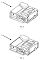
- FIG 1 shows the prior art usually employed in locking a inverter protection housing.
- a cover 2' is fixed to a base 1' by means of a fastening element 3', for protecting the internal elements 4.
- the employ of screws 10' for closing, including for connecting the cable fasteners 9', makes it difficult to open and close the protection housing.
- Figure 2 illustrates a preferred embodiment of the present invention, wherein the cover 2 is fixed to the base 1 by means of a fastening element 3, which does not require the use of screws.
- the cover 2 further has a connection area 8, which aligns with connectors 9 that are part of the internal elements 4 and are fixed to the base 1, is capable of effecting the connection and locking of wires and cables without using cable fasteners 9.
- the connection area 8 is configured for direct fixation of connection cables to connectors 9 that are part of the internal elements 4 of the housing.
- the fastening element 3 of the present invention facilitates the closure of the housing, when necessary. This fastening element does not have the function of closing the housing against tampering, serving only to prevent it from being locked during handling and transportation, preventing a subsequent dismounting process when finishing the production process, thus reducing dismounting costs.
- the fastening element 3 has two different stages for locking the cover 2 to the base.
- the first reversible locking stage a which is represented in figure 3 , is commonly used while storing and transporting the housing, for protection of the internal elements 4. These steps take place when a part of the internal elements 4 of the final product is completed and fixed to the base 1 at place of low production cost.
- a basic example for the case of said compressor inverter is when electric components such as resistors, capacitors and transformers are mounted at the first stage.
- the cover 2 is locked to the base 1 at the reversible locking stage a of the fastening element, which is configured to enable opening the housing for access to the internal elements 4.
- the reversible locking stage a of the fixation element 3 is configured for the housing to be stored and transported in open state, with a vertical spacing between the base 1 and the cover 2, preferably of about 10 mm, so that no device will be necessary to open it.
- the second location may be a room other than the production line of the same factory, or most often another factory, even in another country, the invention being advantageously employed in situations in which this transportation is carried out by mating pieces, that is, wherein kits containing at least one base 1 and one cover 2 are sent to the destination location.
- an expert After transportation of the housing, an expert will revert the reversible locking stage a of the fastening element 3, that is, revert the locking so as to obtain access to the internal elements 4 and to mount the remaining elements, as for example microcontrollers or other specific elements that are more sensitive, while checking the assembly made before. Following this mounting of the remaining internal elements, the product should be tested and, if it is in perfect operation state, the expert will make the final protection of the internal elements 4 of the product by using a second irreversible locking b, as shown in figure 4 , configured for making the anti-tamper closure of the housing. It should be pointed out that the second irreversible locking stage b is irreversible only manually, but it may be reverted, for instance, for maintenance or cleaning at an authorized technical assistance workshop using an appropriate tool.
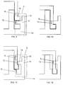
- Figures 5 to 16 illustrate various constructive embodiments that may be applied in creating a fastening element 3 with two different stages, which will be explained in detail hereinafter.
- the fastening element 3 is constituted by a polymer that is injected together with the base, which simplifies the production of the housing.
- Figures 5 and 6 illustrate the preferred embodiment of the present invention, figure 5 being the representation of the fastening element 3 at the reversible locking stage a, and figure 6 being the representation of the fastening element at the irreversible locking state b.
- the fastening element 3 has a connection base 14 at a lower portion, in general constructively linked to the base 1, also in its lower portion. From this connection base 14, the body of the fastening element 3 rises vertically, which further has a division region 11, preferably in a central portion with respect to an opening lock 12 and the connection base 14. This division region 11 separates, preferably orthogonally, the opening lock 12 from a fastening body 13. Additionally, in this embodiment, the cover 2 has a locking protrusion 15.
- the vertical movement of the cover 2 is limited by resting on the fastening body 13, while the horizontal movement of the cover 2 is limited by the opening lock 12.
- the housing can be transported without problems and, additionally, a number of housings may be stacked on each other, the number being limited only by the force that actuates on the fastening body 13, so that the latter will not break.
- the fixation body 13 may be constructed so as to make pressure on the side of the cover 2, as shown in figure 6 , the locking protrusion 15 of the cover additionally limiting the vertical movement of the cover 2.
- the cover 2 is fixedly locked onto the base 1, and it is further defined that the constructive calculation of the fastening element 3 may be carried out so that the lateral movement thereof will cause it to break, that is, if the cover 2 is fixed onto the base 1 by using the irreversible locking stage b, an attempt to open the fastening element 3 will need a force that will cause it to break.
- Figures 7 and 8 describe first alternative embodiment of the fastening element 3, having also a division region 11, an opening lock 12, a fastening body 13 and a connection base 14.
- the distinction of this construction of the fastening element is due to the fact that the base 1 additionally comprises a relief 5, configured to aid in fixing the cover 2. It is noted, in this embodiment, that the vertical movement of the cover 2 is limited by the relief 5, by the fastening body 13 and by the locking protrusion 15. In this way, it is possible to stack more housings, since the maximum number of housings to be stacked is limited, in this construction, by the force on the relief 5, not by the force on the fastening body 13. Since the relief 5 is constructed adjacent the side of the base 1, it has much greater resistance than the fastening body 13.
- this construction has a possible angulation of the body of the fastening element 3 with respect to the connection base 14, resulting in greater pressure of the fastening body 13 onto the cover 2. Additionally, this construction has an angulation on the fastening body 13 to increase the pressure on the cover 2 as well.
- FIGS 9 and 10 illustrate a second alternative embodiment of the fixation element 3.
- this embodiment comprises a division region 11, an opening lock 12, a fastening body 13 and a connection base 14.
- the cover 2 also comprises, in this construction, a recess 6, which further increases the locking security of the cover 2 on the base 1.
- the irreversible locking stage b is configured so as to cause a part of the fastening body 13 to be inserted into the recess 6 of the cover.
- the fastening body 13 inserted into the recess 6 will also exert a vertical force that prevents such movement.
- the fastening body 13 and, consequently, the recess 6, may be prolonged into the cover, so that it will be virtually impossible to withdraw it after engagement.
- the recess 6 should have dimensions sufficient for insertion of the fastening body 13, without leaving space for the fastening body 13 to move and cause a clearance of the fastening element.
- the recess 6 has a rectangular geometry of dimensions that are somewhat larger than he dimensions of the fastening body 13.
- Figures 11 and 12 show a third alternative embodiment of fastening element 3, which makes use of the elements presented by figures 9 and 10 in conjunction with the relief 5, shown in figures 7 and 8 before. In.this way, the double fixation of the system by using the relief 5 and the fastening body 13 inserted into the recess 6 results in greater security for the irreversible locking stage b.
- FIGS. 13 and 14 further show an additional fastening body 16, besides the elements already explained, which are a division regions 11, an opening lock 12, a fastening body 13 and a connection base 14, all of them on the fastening element 3, and additionally the locking protrusion 15 on the cover 2.
- the additional fixation element 16 should preferably be parallel to the fastening body 13 and have a width smaller than that of the fastening body 13, in order to facilitate further the disengagement of the additional fastening body from the recess 6.
- the additional fastening body 16 may be configured to have greater height than the recess 6 and, therefore, not be inserted in such a recess.
- FIG. 15 and 16 of the present invention illustrates an additional oriented recess 7 on the base 1.
- Such an additional oriented recess 7 may have substantially the same dimensions and geometries of the recess 6 of the cover 2 and may be substantially at the same position with respect to the fastening body 13 of the fastening element 3. In this way, the fastening body 13 is configured to be inserted into the recess 6 and into the oriented recess 7 simultaneously.
- the cover 2 has a locking protrusion 15, such a region serves only as anti-opening guaranty after the locking using the irreversible locking stage b.
- the cover 2 may be constructed with a smooth part and, therefore, without the locking region, being fixed only by the pressure exerted by the fastening body 13.
- adhesive materials or glues generally on the fastening body 13, for better fixation and irreversibility of the locking.
- the side body of the fastening element 3 should have, preferably, between 5% and 80% of the side of the cover 2.
- figures 2 and 4 show a fastening element 3 with a side body having approximately 10% of the side body of the cover 2.
- this fastening element 3 and of the protection housing are preferably employed in the construction of a housing of a inverter for electric compressors. Therefore, a inverter that uses the housing and the compressor using such a inverter are within the scope of this invention.
Landscapes
- Engineering & Computer Science (AREA)
- Microelectronics & Electronic Packaging (AREA)
- Computer Security & Cryptography (AREA)
- Connection Of Plates (AREA)
- Casings For Electric Apparatus (AREA)
- Compressor (AREA)
Claims (15)
- Ein System zum Sichern von Gehäusen, die eine Basis (1), eine Bedeckung (2) und interne Elemente (4), die in einem inneren Teilbereich der Basis (1) angeordnet sind, umfassen,
wobei die Bedeckung (2) auf der Basis (1) gesichert ist vermittels zumindest eines Befestigungselementes (3),
wobei das Sicherungssystem dadurch gekennzeichnet ist, dass das Befestigungselement (3) eine erste reversible Sicherungsstufe (a) und eine zweite irreversible Sicherungsstufe (b) hat,
wobei das Sicherungssystem so ausgebildet ist, dass die reversible Sicherungsstufe (a) es jemandem ermöglicht, das Gehäuse zu öffnen für einen Zugang zu den internen Elementen (4), und dass die irreversible Sicherungsstufe (b) die gegen unerlaubte Änderungen sichere Schließung des Gehäuses bewirkt. - Das Gehäusesicherungssystem gemäß Anspruch 1, dadurch gekennzeichnet, dass die Basis (1) eine Kontur (5) zum Sichern der Bedeckung (2) in der reversiblen Sicherungsstufe (a) aufweist.
- Das Gehäusesicherungssystem gemäß Anspruch 2, dadurch gekennzeichnet, dass die Kontur (5) ausgebildet ist zum Halten einer vertikalen Distanz von im Wesentlichen 10 mm zwischen der Basis (1) und der Bedeckung (2).
- Das Gehäusesicherungssystem gemäß Anspruch 1, 2 oder 3, dadurch gekennzeichnet, dass das Befestigungselement (3) höchstens 80 % der Basislänge (1) umfasst.
- Das Gehäusesicherungssystem gemäß Anspruch 1, 2, 3 oder 4, dadurch gekennzeichnet, dass die Bedeckung (2) eine Vertiefung (6) zum Einbringen eines Befestigungskörpers (13) des Befestigungselements (3) aufweist.
- Das Gehäusesicherungssystem gemäß Anspruch 5, dadurch gekennzeichnet, dass die Vertiefung (6) eine eckige Geometrie aufweist.
- Das Gehäusesicherungssystem gemäß Anspruch 1, 2, 3, 4, 5 oder 6, dadurch gekennzeichnet, dass die Basis (1) eine ausgerichtete Vertiefung (7) zum Einbringen eines Befestigungskörpers (13) des Befestigungselements (3) aufweist.
- Das Gehäusesicherungssystem gemäß Anspruch 7, dadurch gekennzeichnet, dass die ausgerichtete Vertiefung (7) der Basis (1) im Wesentlichen dieselben Dimensionen und Geometrien von der Vertiefung (6) der Bedeckung (2) aufweist und im Wesentlichen in derselben Position in Bezug auf den Befestigungskörper (13), ausgebildet zum simultanen Einbringen in die Vertiefung (6) und in die ausgerichtete Vertiefung (7), ist.
- Das Gehäusesicherungssystem gemäß Anspruch 1, 2, 3, 4, 5 oder 7, dadurch gekennzeichnet, dass die Bedeckung (2) einen Einbringbereich (8) zum Fixieren eines Verbindungskabels unmittelbar an den Verbindungen (9), die ein Teil der internen Elemente (4) des Gehäuses sind, aufweist.
- Das Gehäusesicherungssystem gemäß Anspruch 1, 2, 3, 4, 5 oder 9, dadurch gekennzeichnet, dass es mehr als ein Befestigungselement (3) aufweist.
- Das Gehäusesicherungssystem gemäß Anspruch 1, dadurch gekennzeichnet, dass das Befestigungselement (3) einen Trennungsabschnitt (11), eine Öffnungssicherung (12), einen Befestigungskörper (13) und eine Verbindungsbasis (14) umfasst, wobei die Verbindungsbasis (14) konstruktiv verbunden ist mit der Basis (1) an ihrem unteren Teilbereich von der Verbindungsbasis (14), wobei sich der Körper des Befestigungselements (3) vertikal erhebt, wobei der Trennungsabschnitt (11) in einer zentralen Position in Bezug auf die Öffnungssicherung (12) angeordnet ist und wobei der Trennungsabschnitt (11) die Öffnungssicherung (12) orthogonal von dem Befestigungskörper (13) trennt.
- Das Gehäusesicherungssystem gemäß Anspruch 11, dadurch gekennzeichnet, dass die Bedeckung (2) darüber hinaus einen Sicherungsvorsprung (15) und eine Vertiefung (6) umfasst, so ausgebildet, dass der Befestigungskörper (13) in die Vertiefung (6) einbringbar ist.
- Ein elektrischer Kompressor-Inverter, gekennzeichnet durch eine Verwendung eines Sicherungssystems wie es in einem der Ansprüche 1 bis 12 definiert ist.
- Ein elektrischer Kompressor, gekennzeichnet durch Verwenden eines Inverters wie er in Anspruch 13 definiert ist.
- Ein Verfahren zum Sichern von Gehäusen für elektrische Kompressor-Inverter, wobei die Gehäuse eine Basis (1), eine Bedeckung (2), ein Befestigungselement (3) und interne Elemente (4) umfassen, wobei das Verfahren gekennzeichnet ist, dann die folgenden Schritte zu umfassen:(a) Anbringen eines Teils der internen Elemente (4) auf der Basis (1);(b) Sichern der Bedeckung (2) auf der Basis (1) vermittels einer ersten reversiblen Sicherungsstufe (a) des Befestigungselements (3), ausgebildet zum Halten eines vertikalen Abstands zwischen der Basis (1) und der Bedeckung (2) und zum Ermöglichen eines Öffnens des Gehäuses, um Zugang zu haben zu den internen Elementen (4);(c) Umkehren des Sicherns des Gehäuses und Anbringen der restlichen internen Elemente (4) auf der Basis (1);(d) Sichern der Bedeckung (2) auf der Basis (1) vermittels der irreversiblen Sicherungsstufe (b) des Befestigungselements (3), ausgebildet zum Bewirken einer gegen unerlaubte Änderungen sicheren Schließung des Gehäuses und zum Schützen der internen Elemente (4), die auf der Basis (1) angebracht sind.
Applications Claiming Priority (2)
| Application Number | Priority Date | Filing Date | Title |
|---|---|---|---|
| BRBR102012011804-1A BR102012011804A2 (pt) | 2012-05-17 | 2012-05-17 | Elemento de fixação de caixas, sistema e método de travamento de caixas, compressor e inversor |
| PCT/BR2013/000171 WO2013170331A1 (pt) | 2012-05-17 | 2013-05-17 | Sistema de travamento de caixas |
Publications (2)
| Publication Number | Publication Date |
|---|---|
| EP2852265A1 EP2852265A1 (de) | 2015-03-25 |
| EP2852265B1 true EP2852265B1 (de) | 2016-10-05 |
Family
ID=48747253
Family Applications (1)
| Application Number | Title | Priority Date | Filing Date |
|---|---|---|---|
| EP13734305.9A Not-in-force EP2852265B1 (de) | 2012-05-17 | 2013-05-17 | Verriegelungssystem für gehäuse |
Country Status (5)
| Country | Link |
|---|---|
| US (1) | US9497870B2 (de) |
| EP (1) | EP2852265B1 (de) |
| CN (1) | CN104604348B (de) |
| BR (1) | BR102012011804A2 (de) |
| WO (1) | WO2013170331A1 (de) |
Family Cites Families (11)
| Publication number | Priority date | Publication date | Assignee | Title |
|---|---|---|---|---|
| DE3346243C2 (de) * | 1983-12-21 | 1986-09-18 | Siemens AG, 1000 Berlin und 8000 München | Schnappverbindung zwischen zwei Elementen |
| JP3154070B2 (ja) * | 1991-12-24 | 2001-04-09 | 松下電工株式会社 | 防滴型ロビーインターホン |
| CN2904578Y (zh) * | 2006-01-24 | 2007-05-23 | 加西贝拉压缩机有限公司 | 一种冰箱压缩机电器盒 |
| DE102006061703A1 (de) | 2006-12-28 | 2008-07-03 | Robert Bosch Gmbh | Verbindungsanordnung |
| DE102007051716B4 (de) | 2007-10-30 | 2009-10-08 | Behr-Hella Thermocontrol Gmbh | Gehäuse für eine Kfz-Bedieneinheit |
| JP4932756B2 (ja) * | 2008-02-01 | 2012-05-16 | 矢崎総業株式会社 | 部品を内部に収容した箱体 |
| JP5433313B2 (ja) * | 2009-06-11 | 2014-03-05 | 矢崎総業株式会社 | 防水ボックス |
| CN102104348B (zh) * | 2009-12-22 | 2013-04-17 | 泰科电子(上海)有限公司 | 太阳能光伏接线盒组件 |
| US8723031B2 (en) * | 2010-08-30 | 2014-05-13 | Hosiden Corporation | Terminal box |
| JP5789152B2 (ja) * | 2011-08-03 | 2015-10-07 | 矢崎総業株式会社 | 電気接続箱 |
| JP5954782B2 (ja) * | 2012-08-10 | 2016-07-20 | 矢崎総業株式会社 | 電気接続箱 |
-
2012
- 2012-05-17 BR BRBR102012011804-1A patent/BR102012011804A2/pt not_active IP Right Cessation
-
2013
- 2013-05-17 CN CN201380025885.4A patent/CN104604348B/zh not_active Expired - Fee Related
- 2013-05-17 WO PCT/BR2013/000171 patent/WO2013170331A1/pt not_active Ceased
- 2013-05-17 EP EP13734305.9A patent/EP2852265B1/de not_active Not-in-force
- 2013-05-17 US US14/401,387 patent/US9497870B2/en not_active Expired - Fee Related
Also Published As
| Publication number | Publication date |
|---|---|
| CN104604348B (zh) | 2017-02-01 |
| US20150145396A1 (en) | 2015-05-28 |
| CN104604348A (zh) | 2015-05-06 |
| BR102012011804A2 (pt) | 2014-04-29 |
| EP2852265A1 (de) | 2015-03-25 |
| US9497870B2 (en) | 2016-11-15 |
| WO2013170331A1 (pt) | 2013-11-21 |
Similar Documents
| Publication | Publication Date | Title |
|---|---|---|
| US8408609B2 (en) | Safety lockout hasp | |
| US11444438B2 (en) | Switch cabinet frame structure having closed base frame | |
| JP7032000B2 (ja) | 電気接続箱及びワイヤハーネス | |
| JP5707182B2 (ja) | 電気接続箱 | |
| JP5146549B2 (ja) | 電子部品収納体および端子接続部構造 | |
| KR101676530B1 (ko) | 자체-장착 특징부를 구비한 하우징 | |
| EP2852265B1 (de) | Verriegelungssystem für gehäuse | |
| US9042111B2 (en) | Secure raceway with lockable access | |
| US20080023361A1 (en) | Disk holding device | |
| BR112018004293B1 (pt) | Selo de garantia inviolável para medidores de consumo de energia elétrica | |
| CN104405229A (zh) | 一种人脸识别保险箱 | |
| DE102009022645A1 (de) | Klemmendeckel für einen Elektrizitätszähler | |
| US20090154072A1 (en) | Watthour meter box flange and method for installation of same | |
| US20120140381A1 (en) | Watthour Meter Box Flange and Method for Installation of Same | |
| Derock et al. | Convergence of the latest standards addressing safety and security for information technology | |
| US6176111B1 (en) | Drum security system | |
| WO2012123460A1 (en) | Plug element with strain relief organ | |
| US20190259308A1 (en) | Seal assembly for utility meter and associated methods | |
| EP3239807A1 (de) | Manipulationssichere abdeckung | |
| WO2007042756A1 (en) | Electricity meter | |
| ES2607829T3 (es) | Sistema de bloqueo de una carcasa | |
| CN213653520U (zh) | 电子标识器防拆装置及电子标识器系统 | |
| US20140029169A1 (en) | Securing Apparatus and System | |
| US20090201633A1 (en) | Watthour Meter Box Flange and Method For Installation of Same | |
| US10666024B2 (en) | Housing for an electrical appliance |
Legal Events
| Date | Code | Title | Description |
|---|---|---|---|
| PUAI | Public reference made under article 153(3) epc to a published international application that has entered the european phase |
Free format text: ORIGINAL CODE: 0009012 |
|
| 17P | Request for examination filed |
Effective date: 20141121 |
|
| AK | Designated contracting states |
Kind code of ref document: A1 Designated state(s): AL AT BE BG CH CY CZ DE DK EE ES FI FR GB GR HR HU IE IS IT LI LT LU LV MC MK MT NL NO PL PT RO RS SE SI SK SM TR |
|
| AX | Request for extension of the european patent |
Extension state: BA ME |
|
| DAX | Request for extension of the european patent (deleted) | ||
| GRAP | Despatch of communication of intention to grant a patent |
Free format text: ORIGINAL CODE: EPIDOSNIGR1 |
|
| INTG | Intention to grant announced |
Effective date: 20160504 |
|
| GRAS | Grant fee paid |
Free format text: ORIGINAL CODE: EPIDOSNIGR3 |
|
| GRAA | (expected) grant |
Free format text: ORIGINAL CODE: 0009210 |
|
| AK | Designated contracting states |
Kind code of ref document: B1 Designated state(s): AL AT BE BG CH CY CZ DE DK EE ES FI FR GB GR HR HU IE IS IT LI LT LU LV MC MK MT NL NO PL PT RO RS SE SI SK SM TR |
|
| REG | Reference to a national code |
Ref country code: GB Ref legal event code: FG4D |
|
| REG | Reference to a national code |
Ref country code: CH Ref legal event code: EP |
|
| REG | Reference to a national code |
Ref country code: AT Ref legal event code: REF Ref document number: 835574 Country of ref document: AT Kind code of ref document: T Effective date: 20161015 |
|
| REG | Reference to a national code |
Ref country code: IE Ref legal event code: FG4D |
|
| REG | Reference to a national code |
Ref country code: DE Ref legal event code: R096 Ref document number: 602013012430 Country of ref document: DE |
|
| REG | Reference to a national code |
Ref country code: NL Ref legal event code: MP Effective date: 20161005 |
|
| REG | Reference to a national code |
Ref country code: LT Ref legal event code: MG4D |
|
| PG25 | Lapsed in a contracting state [announced via postgrant information from national office to epo] |
Ref country code: LV Free format text: LAPSE BECAUSE OF FAILURE TO SUBMIT A TRANSLATION OF THE DESCRIPTION OR TO PAY THE FEE WITHIN THE PRESCRIBED TIME-LIMIT Effective date: 20161005 |
|
| REG | Reference to a national code |
Ref country code: AT Ref legal event code: MK05 Ref document number: 835574 Country of ref document: AT Kind code of ref document: T Effective date: 20161005 |
|
| PG25 | Lapsed in a contracting state [announced via postgrant information from national office to epo] |
Ref country code: NO Free format text: LAPSE BECAUSE OF FAILURE TO SUBMIT A TRANSLATION OF THE DESCRIPTION OR TO PAY THE FEE WITHIN THE PRESCRIBED TIME-LIMIT Effective date: 20170105 Ref country code: SE Free format text: LAPSE BECAUSE OF FAILURE TO SUBMIT A TRANSLATION OF THE DESCRIPTION OR TO PAY THE FEE WITHIN THE PRESCRIBED TIME-LIMIT Effective date: 20161005 Ref country code: LT Free format text: LAPSE BECAUSE OF FAILURE TO SUBMIT A TRANSLATION OF THE DESCRIPTION OR TO PAY THE FEE WITHIN THE PRESCRIBED TIME-LIMIT Effective date: 20161005 |
|
| REG | Reference to a national code |
Ref country code: FR Ref legal event code: PLFP Year of fee payment: 5 |
|
| PG25 | Lapsed in a contracting state [announced via postgrant information from national office to epo] |
Ref country code: FI Free format text: LAPSE BECAUSE OF FAILURE TO SUBMIT A TRANSLATION OF THE DESCRIPTION OR TO PAY THE FEE WITHIN THE PRESCRIBED TIME-LIMIT Effective date: 20161005 Ref country code: NL Free format text: LAPSE BECAUSE OF FAILURE TO SUBMIT A TRANSLATION OF THE DESCRIPTION OR TO PAY THE FEE WITHIN THE PRESCRIBED TIME-LIMIT Effective date: 20161005 Ref country code: PL Free format text: LAPSE BECAUSE OF FAILURE TO SUBMIT A TRANSLATION OF THE DESCRIPTION OR TO PAY THE FEE WITHIN THE PRESCRIBED TIME-LIMIT Effective date: 20161005 Ref country code: HR Free format text: LAPSE BECAUSE OF FAILURE TO SUBMIT A TRANSLATION OF THE DESCRIPTION OR TO PAY THE FEE WITHIN THE PRESCRIBED TIME-LIMIT Effective date: 20161005 Ref country code: RS Free format text: LAPSE BECAUSE OF FAILURE TO SUBMIT A TRANSLATION OF THE DESCRIPTION OR TO PAY THE FEE WITHIN THE PRESCRIBED TIME-LIMIT Effective date: 20161005 Ref country code: AT Free format text: LAPSE BECAUSE OF FAILURE TO SUBMIT A TRANSLATION OF THE DESCRIPTION OR TO PAY THE FEE WITHIN THE PRESCRIBED TIME-LIMIT Effective date: 20161005 Ref country code: PT Free format text: LAPSE BECAUSE OF FAILURE TO SUBMIT A TRANSLATION OF THE DESCRIPTION OR TO PAY THE FEE WITHIN THE PRESCRIBED TIME-LIMIT Effective date: 20170206 Ref country code: IS Free format text: LAPSE BECAUSE OF FAILURE TO SUBMIT A TRANSLATION OF THE DESCRIPTION OR TO PAY THE FEE WITHIN THE PRESCRIBED TIME-LIMIT Effective date: 20170205 Ref country code: BE Free format text: LAPSE BECAUSE OF FAILURE TO SUBMIT A TRANSLATION OF THE DESCRIPTION OR TO PAY THE FEE WITHIN THE PRESCRIBED TIME-LIMIT Effective date: 20161005 |
|
| REG | Reference to a national code |
Ref country code: SK Ref legal event code: T3 Ref document number: E 23105 Country of ref document: SK |
|
| REG | Reference to a national code |
Ref country code: DE Ref legal event code: R097 Ref document number: 602013012430 Country of ref document: DE |
|
| PG25 | Lapsed in a contracting state [announced via postgrant information from national office to epo] |
Ref country code: EE Free format text: LAPSE BECAUSE OF FAILURE TO SUBMIT A TRANSLATION OF THE DESCRIPTION OR TO PAY THE FEE WITHIN THE PRESCRIBED TIME-LIMIT Effective date: 20161005 Ref country code: DK Free format text: LAPSE BECAUSE OF FAILURE TO SUBMIT A TRANSLATION OF THE DESCRIPTION OR TO PAY THE FEE WITHIN THE PRESCRIBED TIME-LIMIT Effective date: 20161005 Ref country code: CZ Free format text: LAPSE BECAUSE OF FAILURE TO SUBMIT A TRANSLATION OF THE DESCRIPTION OR TO PAY THE FEE WITHIN THE PRESCRIBED TIME-LIMIT Effective date: 20161005 Ref country code: RO Free format text: LAPSE BECAUSE OF FAILURE TO SUBMIT A TRANSLATION OF THE DESCRIPTION OR TO PAY THE FEE WITHIN THE PRESCRIBED TIME-LIMIT Effective date: 20161005 |
|
| PGFP | Annual fee paid to national office [announced via postgrant information from national office to epo] |
Ref country code: SK Payment date: 20170519 Year of fee payment: 5 Ref country code: FR Payment date: 20170525 Year of fee payment: 5 Ref country code: GB Payment date: 20170530 Year of fee payment: 5 Ref country code: DE Payment date: 20170530 Year of fee payment: 5 |
|
| PLBE | No opposition filed within time limit |
Free format text: ORIGINAL CODE: 0009261 |
|
| STAA | Information on the status of an ep patent application or granted ep patent |
Free format text: STATUS: NO OPPOSITION FILED WITHIN TIME LIMIT |
|
| PG25 | Lapsed in a contracting state [announced via postgrant information from national office to epo] |
Ref country code: BG Free format text: LAPSE BECAUSE OF FAILURE TO SUBMIT A TRANSLATION OF THE DESCRIPTION OR TO PAY THE FEE WITHIN THE PRESCRIBED TIME-LIMIT Effective date: 20170105 Ref country code: SM Free format text: LAPSE BECAUSE OF FAILURE TO SUBMIT A TRANSLATION OF THE DESCRIPTION OR TO PAY THE FEE WITHIN THE PRESCRIBED TIME-LIMIT Effective date: 20161005 Ref country code: LU Free format text: LAPSE BECAUSE OF NON-PAYMENT OF DUE FEES Effective date: 20170531 |
|
| PGFP | Annual fee paid to national office [announced via postgrant information from national office to epo] |
Ref country code: IT Payment date: 20170524 Year of fee payment: 5 Ref country code: ES Payment date: 20170601 Year of fee payment: 5 |
|
| 26N | No opposition filed |
Effective date: 20170706 |
|
| PG25 | Lapsed in a contracting state [announced via postgrant information from national office to epo] |
Ref country code: SI Free format text: LAPSE BECAUSE OF FAILURE TO SUBMIT A TRANSLATION OF THE DESCRIPTION OR TO PAY THE FEE WITHIN THE PRESCRIBED TIME-LIMIT Effective date: 20161005 |
|
| REG | Reference to a national code |
Ref country code: CH Ref legal event code: PL |
|
| PG25 | Lapsed in a contracting state [announced via postgrant information from national office to epo] |
Ref country code: MC Free format text: LAPSE BECAUSE OF FAILURE TO SUBMIT A TRANSLATION OF THE DESCRIPTION OR TO PAY THE FEE WITHIN THE PRESCRIBED TIME-LIMIT Effective date: 20161005 |
|
| REG | Reference to a national code |
Ref country code: IE Ref legal event code: MM4A |
|
| PG25 | Lapsed in a contracting state [announced via postgrant information from national office to epo] |
Ref country code: CH Free format text: LAPSE BECAUSE OF NON-PAYMENT OF DUE FEES Effective date: 20170531 Ref country code: LI Free format text: LAPSE BECAUSE OF NON-PAYMENT OF DUE FEES Effective date: 20170531 |
|
| PG25 | Lapsed in a contracting state [announced via postgrant information from national office to epo] |
Ref country code: LU Free format text: LAPSE BECAUSE OF NON-PAYMENT OF DUE FEES Effective date: 20170517 |
|
| PG25 | Lapsed in a contracting state [announced via postgrant information from national office to epo] |
Ref country code: IE Free format text: LAPSE BECAUSE OF NON-PAYMENT OF DUE FEES Effective date: 20170517 |
|
| PG25 | Lapsed in a contracting state [announced via postgrant information from national office to epo] |
Ref country code: MT Free format text: LAPSE BECAUSE OF NON-PAYMENT OF DUE FEES Effective date: 20170517 |
|
| REG | Reference to a national code |
Ref country code: DE Ref legal event code: R119 Ref document number: 602013012430 Country of ref document: DE |
|
| GBPC | Gb: european patent ceased through non-payment of renewal fee |
Effective date: 20180517 |
|
| PG25 | Lapsed in a contracting state [announced via postgrant information from national office to epo] |
Ref country code: SK Free format text: LAPSE BECAUSE OF NON-PAYMENT OF DUE FEES Effective date: 20180517 |
|
| REG | Reference to a national code |
Ref country code: SK Ref legal event code: MM4A Ref document number: E 23105 Country of ref document: SK Effective date: 20180517 |
|
| REG | Reference to a national code |
Ref country code: GB Ref legal event code: 732E Free format text: REGISTERED BETWEEN 20190314 AND 20190320 |
|
| PG25 | Lapsed in a contracting state [announced via postgrant information from national office to epo] |
Ref country code: FR Free format text: LAPSE BECAUSE OF NON-PAYMENT OF DUE FEES Effective date: 20180531 Ref country code: DE Free format text: LAPSE BECAUSE OF NON-PAYMENT OF DUE FEES Effective date: 20181201 Ref country code: GB Free format text: LAPSE BECAUSE OF NON-PAYMENT OF DUE FEES Effective date: 20180517 Ref country code: IT Free format text: LAPSE BECAUSE OF NON-PAYMENT OF DUE FEES Effective date: 20180517 |
|
| PG25 | Lapsed in a contracting state [announced via postgrant information from national office to epo] |
Ref country code: HU Free format text: LAPSE BECAUSE OF FAILURE TO SUBMIT A TRANSLATION OF THE DESCRIPTION OR TO PAY THE FEE WITHIN THE PRESCRIBED TIME-LIMIT; INVALID AB INITIO Effective date: 20130517 |
|
| REG | Reference to a national code |
Ref country code: ES Ref legal event code: FD2A Effective date: 20190913 |
|
| PG25 | Lapsed in a contracting state [announced via postgrant information from national office to epo] |
Ref country code: CY Free format text: LAPSE BECAUSE OF FAILURE TO SUBMIT A TRANSLATION OF THE DESCRIPTION OR TO PAY THE FEE WITHIN THE PRESCRIBED TIME-LIMIT Effective date: 20161005 Ref country code: ES Free format text: LAPSE BECAUSE OF NON-PAYMENT OF DUE FEES Effective date: 20180518 |
|
| PG25 | Lapsed in a contracting state [announced via postgrant information from national office to epo] |
Ref country code: MK Free format text: LAPSE BECAUSE OF FAILURE TO SUBMIT A TRANSLATION OF THE DESCRIPTION OR TO PAY THE FEE WITHIN THE PRESCRIBED TIME-LIMIT Effective date: 20161005 |
|
| PG25 | Lapsed in a contracting state [announced via postgrant information from national office to epo] |
Ref country code: TR Free format text: LAPSE BECAUSE OF FAILURE TO SUBMIT A TRANSLATION OF THE DESCRIPTION OR TO PAY THE FEE WITHIN THE PRESCRIBED TIME-LIMIT Effective date: 20161005 |
|
| PG25 | Lapsed in a contracting state [announced via postgrant information from national office to epo] |
Ref country code: GR Free format text: LAPSE BECAUSE OF FAILURE TO SUBMIT A TRANSLATION OF THE DESCRIPTION OR TO PAY THE FEE WITHIN THE PRESCRIBED TIME-LIMIT Effective date: 20161005 |
|
| PG25 | Lapsed in a contracting state [announced via postgrant information from national office to epo] |
Ref country code: AL Free format text: LAPSE BECAUSE OF FAILURE TO SUBMIT A TRANSLATION OF THE DESCRIPTION OR TO PAY THE FEE WITHIN THE PRESCRIBED TIME-LIMIT Effective date: 20161005 |