EP2848561A1 - Procédé et dispositif de déplacement horizontal d'emplacements d'articles entre des modules voisins - Google Patents
Procédé et dispositif de déplacement horizontal d'emplacements d'articles entre des modules voisins Download PDFInfo
- Publication number
- EP2848561A1 EP2848561A1 EP14179907.2A EP14179907A EP2848561A1 EP 2848561 A1 EP2848561 A1 EP 2848561A1 EP 14179907 A EP14179907 A EP 14179907A EP 2848561 A1 EP2848561 A1 EP 2848561A1
- Authority
- EP
- European Patent Office
- Prior art keywords
- conveyor module
- article
- module
- support plane
- support
- Prior art date
- Legal status (The legal status is an assumption and is not a legal conclusion. Google has not performed a legal analysis and makes no representation as to the accuracy of the status listed.)
- Granted
Links
- 238000000034 method Methods 0.000 title claims abstract description 39
- 238000006073 displacement reaction Methods 0.000 claims abstract description 13
- 230000001360 synchronised effect Effects 0.000 claims description 11
- 238000013459 approach Methods 0.000 claims description 7
- 239000002023 wood Substances 0.000 claims description 3
- 238000012546 transfer Methods 0.000 description 58
- 230000008569 process Effects 0.000 description 10
- 238000000151 deposition Methods 0.000 description 6
- 230000003750 conditioning effect Effects 0.000 description 4
- 238000012545 processing Methods 0.000 description 3
- 230000008901 benefit Effects 0.000 description 2
- 235000013361 beverage Nutrition 0.000 description 2
- 230000008859 change Effects 0.000 description 2
- 238000001514 detection method Methods 0.000 description 2
- 230000000284 resting effect Effects 0.000 description 2
- 230000002123 temporal effect Effects 0.000 description 2
- 238000012549 training Methods 0.000 description 2
- 230000001133 acceleration Effects 0.000 description 1
- 230000009471 action Effects 0.000 description 1
- 150000001875 compounds Chemical class 0.000 description 1
- 230000007423 decrease Effects 0.000 description 1
- 230000003111 delayed effect Effects 0.000 description 1
- 230000008021 deposition Effects 0.000 description 1
- 208000018459 dissociative disease Diseases 0.000 description 1
- 230000000694 effects Effects 0.000 description 1
- 230000002996 emotional effect Effects 0.000 description 1
- 230000003993 interaction Effects 0.000 description 1
- 239000000463 material Substances 0.000 description 1
- 238000012986 modification Methods 0.000 description 1
- 230000004048 modification Effects 0.000 description 1
- 230000009467 reduction Effects 0.000 description 1
- 238000005096 rolling process Methods 0.000 description 1
- 238000000926 separation method Methods 0.000 description 1
- 230000006641 stabilisation Effects 0.000 description 1
- 238000011105 stabilization Methods 0.000 description 1
- 230000000087 stabilizing effect Effects 0.000 description 1
Images


Classifications
-
- B—PERFORMING OPERATIONS; TRANSPORTING
- B65—CONVEYING; PACKING; STORING; HANDLING THIN OR FILAMENTARY MATERIAL
- B65G—TRANSPORT OR STORAGE DEVICES, e.g. CONVEYORS FOR LOADING OR TIPPING, SHOP CONVEYOR SYSTEMS OR PNEUMATIC TUBE CONVEYORS
- B65G47/00—Article or material-handling devices associated with conveyors; Methods employing such devices
- B65G47/52—Devices for transferring articles or materials between conveyors i.e. discharging or feeding devices
-
- B—PERFORMING OPERATIONS; TRANSPORTING
- B65—CONVEYING; PACKING; STORING; HANDLING THIN OR FILAMENTARY MATERIAL
- B65G—TRANSPORT OR STORAGE DEVICES, e.g. CONVEYORS FOR LOADING OR TIPPING, SHOP CONVEYOR SYSTEMS OR PNEUMATIC TUBE CONVEYORS
- B65G47/00—Article or material-handling devices associated with conveyors; Methods employing such devices
- B65G47/74—Feeding, transfer, or discharging devices of particular kinds or types
- B65G47/84—Star-shaped wheels or devices having endless travelling belts or chains, the wheels or devices being equipped with article-engaging elements
- B65G47/841—Devices having endless travelling belts or chains equipped with article-engaging elements
- B65G47/845—Devices having endless travelling belts or chains equipped with article-engaging elements the article engaging elements being pushers moving in parallel and independently from the supporting conveyor
-
- B—PERFORMING OPERATIONS; TRANSPORTING
- B65—CONVEYING; PACKING; STORING; HANDLING THIN OR FILAMENTARY MATERIAL
- B65G—TRANSPORT OR STORAGE DEVICES, e.g. CONVEYORS FOR LOADING OR TIPPING, SHOP CONVEYOR SYSTEMS OR PNEUMATIC TUBE CONVEYORS
- B65G57/00—Stacking of articles
- B65G57/02—Stacking of articles by adding to the top of the stack
- B65G57/16—Stacking of articles of particular shape
- B65G57/20—Stacking of articles of particular shape three-dimensional, e.g. cubiform, cylindrical
- B65G57/22—Stacking of articles of particular shape three-dimensional, e.g. cubiform, cylindrical in layers each of predetermined arrangement
- B65G57/24—Stacking of articles of particular shape three-dimensional, e.g. cubiform, cylindrical in layers each of predetermined arrangement the layers being transferred as a whole, e.g. on pallets
- B65G57/245—Stacking of articles of particular shape three-dimensional, e.g. cubiform, cylindrical in layers each of predetermined arrangement the layers being transferred as a whole, e.g. on pallets with a stepwise downward movement of the stack
Definitions
- the present invention relates to a method for the horizontal displacement of article groups or layers between adjacent conveyor modules having the features of independent method claim 1.
- the invention also relates to a corresponding device having the features of independent claim 7.
- the articles normally first pass through a grouping station in which the articles which are initially transported in single-row or multi-row succession are moved and / or put together to be able to be palletized. These palletizable layers must be transferred to a suitable loading station that is able to perform lifting movements. The loading station then deposits these article layers at a desired location, for example at a so-called stacking station and a pallet located thereon.
- the provisioning station and the grouping station may optionally be a unit and / or be directly coupled with each other.
- the delivery station and / or the grouping station comprise a support surface or support plane on which the articles are grouped and put together to form a layer.
- the loading station also includes a support plane, which can be made in one piece or two or more parts.
- a support plane which can be made in one piece or two or more parts.
- the support surface consists of two trays or so-called loading plates, which are closed in the loading and then opened during the delivery or storage phase for storing the article location on a stacking or pallet.
- the expert is here numerous variants known, such as Venetian blind heads or the like. In this case, such a palletizing process with a known from the prior art palletizing in such a way that initially articles are assembled by means of a grouping device to a palettierQuen position and subsequently passed from a supply point or a supply station in the loading station.
- the loading station such as a arranged on a hoist or robots Jalouêtreiferkopf, connects to the staging area so that the transfer of the article position can be done in the loading station.
- the blind gripper head or the loading station lingers in place until the position has been completely transferred from the supply station to the loading station.
- the loading station positions itself through horizontal and vertical Moves the article location at a desired delivery location, usually on a provided on a stacking pallet. Thereafter, the same procedure is repeated until the desired number of layers have been deposited on the pallet.
- the DE 10 2008 015 278 A1 discloses an apparatus for loading pallets of general cargo with a cargo delivery station and a translator for translating the group of parcels from the parcel delivery station to a pallet held ready at a stacking location and / or an already transferred parcel of general cargo.
- the EP 1 321 396 A1 discloses another palletizing device in which articles are laterally displaced and grouped laterally by a horizontal conveyor before being transferred to a lifting device in complete layers.
- the lifting device or transfer platform serves as height compensation between the Gruppierstation and the loading station, which stacks the layers stacked and deposits on a pallet by means of an openable rolling ground.
- the device has a support floor for the container with an open front for introducing the container.
- a movable slide is used to move the container along a horizontal direction of picking through the open front.
- the respective affected stations do not perform any vertical and / or movements until the article position has been completely transferred. Either will only after the transfer of the article position, the loading station moved to the respective next delivery position or the loading station is already in the transfer of the article position in the next desired delivery position.
- a primary object of the present invention is to reduce the transfer times between successive stations in stationary and / or vertically movable support levels of successive stations of a transport system.
- the times between the deposition of an article position and the inclusion of a further article position should be minimized.
- each of these stations is associated with at least one bearing surface or support plane, which is suitable for receiving an article position.
- the support plane or bearing surface of the loading station consist of two parts.
- the support plane or bearing surfaces of the provisioning station and / or the transfer station are usually formed in one piece.
- each of the bearing surfaces or bearing planes is also formed by driven circumferential Mattenketten- or roller conveyor o. The like.
- the invention proposes a method for the horizontal transfer or shifting of article groups or article layers from a first support surface or support plane of a first conveyor module to a second, vertically movable support surface or second support plane of a second conveyor module immediately downstream of the first module in a conveying direction in front.
- Transfer can be performed, for example, by means of a suitable transfer device, which can transfer the article group or article position between the two, at least during the overthrusting approximately aligned support planes of the two conveyor modules in the conveying direction.
- This overthrusting device can attack in particular in the conveying direction on the back of the article group or article position to be displaced and, for example, can be formed by a so-called overrunning bar or the like.
- a first stop position may be characterized in that the circumferential overrun bar lowers behind an article position pushed onto the first conveyor module and transfers or pushes it onto the second conveyor module in the horizontal conveying direction.
- the push bar executes a horizontal pushing movement in the conveying direction and is permanently in the height of the article position to be shifted. As soon as his second stop position - possibly also to call end position - has reached, ends his horizontal pushing movement.
- the second stop position is also located within the outline of the first conveyor module, so that the movement range of the slide bar does not extend into the area of the second conveyor module, not even in the second support plane shifted completely in the direction of the first conveyor module.
- the push bar can possibly be pulled vertically upwards and transported above the conveying level of the article layers in horizontal retraction movement back to its first stop position where the push bar can be lowered back to the conveying level of the article layers , Normally, the next article position to be moved is already available there.
- endless and repeated circulating movements of the overflow bar of the transfer device can be effected, for example, by endless circulating traction means on which the overrunning bar is guided laterally.
- the second stop position of the transfer device or the transfer rail-the transfer device or the transfer bar can be returned to its initial position, which in the present context is also the first Stop position is called.
- This horizontal return stroke movement into the first stop position counter to the conveying direction is expediently carried out above or below the conveying plane, so that a further article group or layer already located on the first conveying module can not collide with the returning overthrusting device or with the returning overrunning bar.
- two or more such Studentsubbalken can be arranged on an endless circulating Ceiffenantrieb and thus alternately be prepared for the Studentsub an article position on the second conveyor module and for the return to the first stop position.
- the pushed-over article groups or article layers are displaced shortly before or after reaching the stop position of the overthrust device (in the conveying direction) on the second conveyor module by means of a horizontally movable support surface in the conveying direction and / or centered on the second conveyor module before or during the second conveyor module a vertical lifting movement to place and / or stack the article layer or group on its designated storage or stacking location.
- Waiting times of this second conveyor module can be reduced by means of this - in the course of successive Ausschubterrorismen several article groups or article layers - oscillating movements of the second conveyor module, since due to the movable support plane of the overrun can be completed while already started a lifting or lowering movement of the second conveyor module can be.
- a previously unavoidable waiting time until the overtravel device or a so-called layer slide is moved back towards its other end position and brought out of the collision area with the second conveyor module or the loading station can be saved.
- the vertical movement of the second conveyor module or its support plane which can already be carried out during the concluding phase of the pushing-over movement of the article position or group ensures a reduction or minimization of the required times from the transfer of the article layers to the depositing of the article layers and thus contributes to a temporal distinction or Parallelism of individual process steps, which are necessary for palletizing article layers.
- This temporal and / or procedural separation of individual process steps saves time and thus contributes significantly to an increase in performance of the affected palletizing process. It will be understood by those skilled in the art that in this horizontal transfer, the relative positions of a plurality of articles forming the article group or layer are to be approximately maintained.
- the second conveying module is further assigned a support plane which is movable and / or oscillatable in the horizontal direction between two end positions and which is in its first end position when the article group or article position begins to move past.
- This first end position is characterized in that the support plane is in this case closer to the first conveyor module than in a second end position, where the support plane is located in a farther from the first conveyor module position.
- the horizontally movable support surface is brought at least shortly before the beginning of overturning of the article group or article position on the second conveyor module in the first end position in which it approaches the first conveyor module or this contacted or at least partially on the surface rests.
- the horizontally movable support surface of the second conveyor module or the loading station can move on approaching the overthrusting to an edge adjacent to the second conveyor module edge portion of the first conveyor module or when reaching the second end position, wherein the second support surface parallel to the Kochubraum emotional.
- the layer slider or the overtravel device can thus move as far as the edge of the first support level, so that the edge of the second support level has not yet been reached or exceeded.
- the horizontal transfer of the article group or position takes place at first and second support levels of the first and second delivery modules that are approximately at the same level.
- the bearing planes at least during the sliding movement of the ply slide or the override resting or resting and not move relative to each other in the vertical direction.
- a horizontal movement of the second support plane takes place, which can be combined with an incipient vertical movement of the second conveyor module or its second support plane up or down.
- the advantage of this method is to be seen in particular in the fact that the end time of the transfer of an article position from a first support surface of a first module to a second support level of a second module does not have to wait to already start with a vertical movement of the second support level.
- the vertical positioning of the second conveyor module or the loading station already takes place during the final phase of a pushing-over movement in order, for example, to reach a storage position for depositing, stacking and / or palletizing the article position or article group.
- the overrun processes as a whole - i. in the sum of all necessary process steps - to run in a shorter time or at a higher speed.
- the first support level of the first conveyor module during the transfer of the article group or article position at least time or phase in their height level compared to the second support level of the subsequent second conveyor module to form a level slightly higher or lower lies.
- the articles can, for example, be pushed over a small ramp up or down to the subsequent second module.
- This variant makes it possible that the overthrusting process can possibly be started earlier before the bearing levels are completely aligned with each other, which in turn can save time for the overthrusting process and thus the entire palletizing process.
- the support levels are already largely aligned with each other before the contacting of the second support level with the pushed articles and have achieved the same height level for this purpose.
- the different variants of the method according to the invention make it possible by the coordinated vertical control of at least the second support level of the second module downstream of the first conveyor module that the transfer of the article group or article position from the first support level of the first module to the second support level of the second module immediately before one phase the training of the common support level of the first and second levels of support, or simultaneously with the achievement of this phase. Since the most upright standing articles of a complete article position are not normally on the outermost front edge of the first support level, the overthrusting can already be started without a common support level is already formed. This must be formed, at least approximately, possibly with the acceptance of a slight step, only when the first articles actually pass the boundary between the two bearing planes and are pushed onto the second support plane of the second module.
- first support level of the first module and the second support level of the second module must form the mentioned common support level at least until the article group or article position has been completely transferred to the second support level located in its corresponding end position.
- the common support level can thus be separated immediately after passing the rearmost row of articles of the complete article position, for example by the second support level of the second module performs a superimposed horizontal and vertical movement to approach the filing or stacking.
- the method provides that the support plane of the second conveyor module is formed by a horizontally movable between its two end positions plate having a surface which corresponds at least to the base of a male article group or article position. Normally, however, this plate is at least slightly larger than the article groups or article layers transported therewith, since this is indispensable for a sufficiently stable transport of similar or differently sized article layers or groups.
- the relative positions of a plurality of articles forming the article group or article position are approximately maintained.
- the displacement therefore takes place by means of a suitable overthrust device, which can move the article position between the two approximately aligned bearing planes of the two modules in the conveying direction.
- the Studentsub shark can In particular, be formed by a horizontally movable in the spatial area of the first conveyor module push bar or so-called layer slide o. The like. Which engages in the conveying direction back to the layers to be overshadowed, ie at the respective rearmost located articles of the overlaid layers.
- At least the second conveying module can be positioned vertically, for example in relation to a stacking height of already stacked article layers on a stacking station.
- the reduced overrun times and the vertical movements of at least the second conveyor module, which can already be carried out during the transfer, ensure a minimization of the required transport times and contribute to an acceleration of the achievable conveyor speeds.
- a permanent detection of the current vertical and / or horizontal positions of the support planes as well as the positions of the shifted article layers may be useful, wherein the detected values for calculating a Approach to prepare for a Studentsubvorganges can be processed.
- the aim of this position detection and data processing is an optimally coordinated movement of the two support levels of the successive modules, so that the transfer times are minimized.
- the first module may, for example, be formed by a transfer unit or a transfer table with a vertically movable support plane
- the second module may be formed by a loading station, which likewise comprises a vertically movable support plane.
- a meaningful control provision can provide that a current vertical position of the loading station or of the second support level of the second module dominates the direction of a vertical movement of the transfer unit or the first support level of the first module for approaching the two modules or their support levels.
- the stabilization of the translatable at high speed between adjacent modules or hoists article layers can be achieved by the interaction of the sliding from behind push beam and the optional, stabilizing from the front bearing bar, the article position in this conveyor section can be usefully performed laterally. Due to the back impact of the Push beam and the side guides can be relatively largely maintained relative positions of a group of articles forming the article group relative to each other; ie the layer image of the shifted article group remains largely maintained. This can be achieved essentially by the fact that the optionally to be understood conditioning beam of the article group at least shortly before or when reaching the rest position with a short distance to the foremost articles leads or rests against this.
- the article groups or article layers can be moved from the vertically movable second conveyor module to a second conveyor module immediately downstream in the conveying direction, vertically movable third conveyor module.
- This optional third conveyor module can be formed in particular by a vertically movable loading station or the like, while the second conveyor module can be formed, for example, by a so-called transfer station. It can be provided that the second conveyor module and the third conveyor module during the overthrusting of the article group or article position rest at the same vertical height until the overturning is completed.
- the second conveyor module and the third conveyor module during the transfer operation of the article group or article position execute synchronous synchronous vertical movements, so that prepare in this way the loading station or the third conveyor module already on a subsequent depositing or settling the article position can, for example, on a prepared stacking place with a pallet on it or on an upper side of a previously stored there already article position.
- the present invention further comprises a device for the horizontal displacement of article groups or article layers between at least two support planes of adjacent conveyor modules, while largely maintaining the relative positions of a plurality of articles forming the respectively displaced article group or layer relative to each other.
- This device can in particular a suitable overthrust device for the horizontal displacement of the article layers on the second support level of the second module downstream of the second conveyor module, which is arranged vertically movable include.
- the first and second support planes of the first and second modules at least during the overrunning operation are approximately aligned to allow the smooth horizontal sliding of an article group or layer between the support planes of the modules.
- the second conveyor module has a support plane which is movable and / or oscillatable in the horizontal direction between two end positions and which is placed directly or close to the first conveyor module in the first end position and at least slightly away from the first conveyor module in the second end position and / or opposite the second support plane is approximately centered.
- the oscillating second support plane which can be moved or displaced in the horizontal direction relative to the second conveyor module can be formed, for example, by a support table made of wood or with a wooden surface or a suitable, structured surface, eg also of plastic, which has a sufficient coefficient of friction to prevent uncontrolled slippage of the articles or packages standing thereon when the support table is moved rapidly in the horizontal direction.
- the surface structure should be sufficiently smooth so as not to oppose the thrust movements of the article layer with excessive frictional resistance.
- the horizontal movements of the second support level can be between a few centimeters and typically up to 20 or 25 centimeters, with a meaningful adjustment can be about 8 to 12 ... 15 centimeters, in particular about 10 centimeters. That is, these centimeter specifications define the horizontal distance between the two end positions or end stops of the second support level.
- the first and / or second modules each position sensors for detecting the current vertical and / or horizontal positions of the first and second support levels are assigned, the values of which can be processed to calculate an approach to prepare a Studentsubvorganges.
- the vertical positions and horizontal positions of the support planes can be determined at any time and matched in a control processed signals of the sensors, so that accelerated Kochubterrorismen with simultaneous horizontal movement of the second support level and vertical movement of the second support level bearing second conveyor module are possible.
- the first module can be formed, for example, by a transfer unit or a transfer table or a so-called grouping station or a grouping table with a fixed or possibly also a vertically movable first support level
- the second module can be formed, for example, by a loading station with a vertically movable second support level
- the second module may, for example, also be formed by an elevator and / or a shutter gripper head or another hoisting gear, which enables height compensation. If in the context of the present invention of a height compensation is mentioned, it is meant in particular a stacking possibility in the transfer of the article layers on one of the modules. Since the article layers are stacked in the palletizing usually in several layers one above the other, at least the second conveyor module must have a height adjustment.
- This height adjustment includes both a lowering down to transfer the article layers in a lower level and a liftability above the level of the first module or the Gruppierstation to store the article layers on the top of previously stacked article layers can.
- the push-over device can comprise at least one push bar acting on the articles and / or at least one contact bar engaging at the front on the article position, which is at least temporarily coupled to the push bar in its movement in the push-pull direction and thus prevents the articles from falling over or slipping during rapid push-overs. and can prevent braking.
- at least one of the push beams and / or at least one of the contact beams may be coupled to an endlessly circulating traction drive for producing the thrust movements.
- other drives for the shear and conditioning beams are possible, such as. Linear drives.
- the second, vertically movable conveyor module may also have a suitable overthrusting device in order to be able to transfer or override the article position located there to a further conveying module, for example a loading station or the like, which is not separately mentioned here.
- the second conveyor module associated override may optionally have relatively short ranges of motion, since only a complete transfer to another conveyor element or a pushing down of the article position of the second conveyor module is to ensure.
- this shifting of the article location The second conveyor module also during the vertical movement take place, in particular in a synchronously movable further conveyor module, for example. A corresponding vertical and synchronous to the second conveyor module movable loading station, which is immediately downstream of the second conveyor module.
- the device according to the invention can optionally extend to a further, third conveying module, which can be arranged directly downstream of the second conveying module in the conveying direction.
- the article groups or article layers can be moved from the vertically movable second conveyor module to the vertically movable third conveyor module.
- the optional third conveyor module which is vertically movable like the second conveyor module, can be formed in particular by a so-called loading station or the like, while the second conveyor module can be formed, for example, by a so-called transfer station. It can be provided that the second conveyor module and the third conveyor module during the overthrusting of the article group or article position rest at the same vertical height until the overturning is completed.
- the second conveyor module and the third conveyor module during the transfer operation of the article group or article position execute synchronous synchronous vertical movements, so that prepare in this way the loading station or the third conveyor module already on a subsequent depositing or settling the article position can, for example, on a prepared stacking place with a pallet on it or on an upper side of a previously stored there already article position.
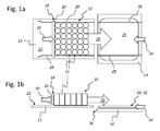
- Fig. 1 shows two schematic views of an incipient pushing movement of an article position from a first conveyor module to an adjacent second conveyor module.
- Fig. 2 to Fig. 9 show, in various successive schematic views, the process steps in the displacement of an article position between two adjacent modules.
- the Fig. 1 shows in a schematic plan view ( Fig. 1a ) and in a schematic side view ( Fig. 1b
- a grouping table which may be part of a grouping, toward a final position in a second conveyor module 14, the example a loading station o. The like. May be.
- the article position 10 comprises in the illustrated embodiment, a regular arrangement of a plurality of articles 16, which are in the rectangular compound and without changing the layer image by means of a push-over 18 in the form of a push bar 20 from a first support level 22 of the first conveyor module 12 to a second support level 24 of the second Feed module 14 to be pushed.
- the articles 16 may be, for example, cartons, containers with several individual articles or containers or even individual containers that are in a regular arrangement next to each other.
- the responsible for the shift of the article group or article position 10 push bar 20 of the overthrust device 18 engages the in relation to the conveying or advancing movement 26 back of the article group 10 located articles 16 and thereby shifts the entire article group or article position 10, which may Maintaining the layer image can be guided laterally.
- the optional side guides are in the Fig. 1a and in the following plan views of FIGS. 2a to 9c each designated by the reference numeral 28.
- the sliding movement of the push beam 20 of the overtube 18 is designated by the reference numeral 30.
- the sliding movement 30 is necessarily the conveying or advancing movement 26 of the shifted with the override 18 to the right article position 10 rectified.
- the second support level 24 which may be formed, for example.
- a support table 32 made of wood or other suitable material, relative to the vertically movable second conveyor module 14 slidably mounted in the horizontal direction.
- This horizontal Relativverschieb sadness can be done between two end positions or end positions.
- a first end position is in the FIGS. 2b (as well as the FIGS. 3b . 4b . 5b and 6b ), in which the second support plane 24 or the support table 32 is close to the first support plane 22 of the first conveyor module 12.
- FIGS. 9b and 9d shown second end characterized in that the support table 32 and the second support level 24 in this case is located at a greater horizontal distance from the first support level 22.
- FIGS. 1a and 1b illustrate a return stroke 34 of the support table 32 with the second support plane 24 in the direction of the first support plane 22.
- the Auflagetisch 32 in the first end position shifting return stroke 34 is thus the conveying or advancing movement 26 of the article position 10 directed against.
- FIGS. 2a ff. can be seen that the return stroke movement 34 ( Fig. 1a, Fig. 1 b) has come to a standstill because the support table 32 has reached its first end position near the first support level 22 of the first conveyor module 12. Since in this case a gap 36 between the two adjoining support planes 22 and 24 is minimal, the article position 10 can be pushed over from the first conveyor module 12 to the second conveyor module 14 largely without problems and without overcoming a disturbing step.
- the advancing movement 26 does not take place at a constant speed, so that the sliding movement 30 of the overthrust device 18 or the push bar 20 can gradually become slower, at least shortly before reaching the target position of the article position 10 on the second conveyor module 14, so that it does not suddenly come to a standstill ,
- the risk that some of the vordemst standing in the displaced article position 10 Article 16 can slip or tip over when the article position 10 is more delayed or suddenly comes to a standstill, especially when reaching the target position of the article layer 10, can optionally by using a not shown here Asset bar can be reduced.
- the first conveying module 12 shown on the left can be formed, for example, by a grouping system or a provisioning station, each of which is grouped one after the other, one after the other Article positions 10 are made available. These article layers 10, which were previously brought into the layer position of the article layer 10 by a sorting and / or grouping system not shown here, are then available on the grouping or grouping system.
- a grouping or sorting system can, for example, comprise one or more handling robots that form closed article layers 10 from one or more article inlets, which are transferred in the manner shown to the first conveying module 12 or the grouping system.
- the grouping system is neither height adjustable nor horizontally displaceable in the illustrated embodiment, but may be arranged in a stationary manner.
- Fig. 1a and Fig. 1b To the in Fig. 1a and Fig. 1b recognizable gap 36 between the first support level 22 of the first conveyor module 12 and the second conveyor module 14 to reduce or bridge, is located in the illustration of Fig. 2a and 2b the horizontally displaceable second support plane 24 and the horizontally displaceable support table 32 in its first end position 38, which is maintained during the entire overthrusting process.
- the support levels 22 and 24 are at the same height, so that a continuous sliding of the article position 10 is possible.
- the displaceable support table 32 has been pushed by means of the return stroke movement 34 to the edge of the first support plane 22 ( Fig. 1a and Fig. 1b ).
- FIG. 6 Top view of Fig. 6a and side view of Fig. 6b ) illustrate the placement of the complete article position 10 with all thirty six articles 16 on the second support level 24 and on the support table 32.
- the push bar 20 has reached the right edge of the first conveyor module 12 and its first support level 22 and thus remains spatially the first Conveyor module 12 assigned while the outermost standing article 16 of the article position 10 are already completely on the support table 32.
- the sliding movement 30 of the push beam 20 ends, while a horizontal movement 40 of the support table 32 of the second support level 24 in the conveying direction and thus parallel to the advancing movement 26 of the article position 10 can be initiated (see. Fig. 6a and Fig. 6b ).
- FIGS. 7a and 7b can recognize, simultaneously with this horizontal movement of the support table 32 and the article position 10 thereon strokes 42 of the second conveyor module 14 together with the support table 32 and a retraction 44 of the push beam 20 of the overthrust 18 are initiated.
- the lifting movement 42 of the second conveyor module 14 down (lowering movement 46; Fig. 8b ) or upwards (lifting movement 48; Fig. 8d ) while the retraction movement 44 of the push beam 20 continues counter to the conveying direction ( Figures 8a, 8b . 8c and 8d and 9a, 9b and 9c and 9d ) and the horizontal movement 40 of the support table 32 to the right can be continued respectively.
- FIGS. 9a to 9d the finished horizontal movement 40 of the support table 32, which has reached its second end position 50, in which the second support level 24 has reached a maximum horizontal distance from the first support level 22.
- the retraction movement of the push beam 20 of the overthrust device 18 can optionally take place in the manner shown above the level of the subsequent article position 10, although in the FIGS. 7a and 7b is not shown, but can already be placed back on the first conveyor plane 22 of the first conveyor module 12.
- This return movement can in principle also take place below the conveying plane 22, if this should be more expedient for constructive reasons.
- a useful embodiment may, for example, provide that, in the interest of a higher processing speed, two or more such overrunning bars 20 are arranged on an endlessly circulating traction drive and thus alternately for the overrun of an article position 10 on the second conveyor module 14 and for the return 44 in the first end position to get prepared.
- FIGS. 7 . 8th and 9 illustrate each simultaneously contiguous strokes 42 (lowering or lifting movement 46, 48) of the second conveyor module 14 with the support table 32 thereon and moving in the horizontal direction between the two end positions 38 and 50 second support level 24, so that on the one hand any collision of the push beam 20 can be avoided with the second conveyor module 14, without this leading to disadvantages in the handling and conveying speeds in the storage and / or palletizing of the article layer 10 on a (not shown) storage or stacking space.
- Such a transfer of the article position 10 can be realized, for example, by means of a Venetian blind or so-called. Plate gripper head, which can unload a complete article position 10 down by opening or lateral displacement of its sliding bottom.
- the second conveyor module 14 in a (not shown here) return stroke movement again according to Fig. 1 be positioned so that the support planes 22 and 24 are aligned.
- the second support plane 24 can be moved back in the return stroke 34 from the second end 50 in the first end position 38, so that a further article position 10 can be pushed in the manner described between the two conveyor modules 12 and 14.
- a further, not shown here variant of the stacking method may optionally provide that on the loading station (the second conveyor module 14) a plurality of article layers 10 are stored simultaneously. Due to the simultaneous handling and stacking of several article layers 10, if necessary, the pallet change times can be significantly reduced. As a result, the loading station acts as a kind of cache, whereby the times required for a pallet change can be minimized.
- the second, vertically movable delivery module 14 may also have a further transfer device (not shown) for transferring the article layer 10 located there to another delivery module (not specifically mentioned here), for example a loading station or the like to be able to override.
- a further transfer device for transferring the article layer 10 located there to another delivery module (not specifically mentioned here), for example a loading station or the like to be able to override.
- the second conveyor module 14 associated override may possibly have relatively short ranges of motion, since only a complete transfer to another conveyor element or a pushing down of the article position 10 is to ensure the second conveyor module 14.
- this shifting of the article position 10 from the second conveyor module 14 can also take place during its vertical movement, in particular in the case of a further movement which is synchronous therewith Conveying module, for example, a corresponding vertically and synchronously to the second conveyor module 14 movable loading station, which may be the second conveyor module 14 immediately downstream.
- Conveying module for example, a corresponding vertically and synchronously to the second conveyor module 14 movable loading station, which may be the second conveyor module 14 immediately downstream.
- the first conveyor module 12 is to be designated as a provisioning module or as a grouping module
- the second conveyor module 14 is to be regarded or designated in particular as a transfer station or as a transfer module.
- a following third conveyor module (not shown), which may be synchronous or independent of the second conveyor module 14, may in this case be formed by a loading station or a loading module or the like.
- the second conveyor module 14 and the third conveyor module, not shown here each have their own overrunning devices for transferring the article position 10 in the conveying direction.
- the oscillating movable second support level 24 of the second conveyor module 14 thus moves between the first conveyor module 12 and a third conveyor module not shown here, the second conveyor module 14 downstream in the conveying direction, so that all gaps in the conveying and support plane between the individual modules of the horizontally between its two end positions 38 and 50 movable second support level 24 can be balanced and bridged.
- the sliding over of the article position 10 from the second conveyor module 14 to a third conveyor module can be facilitated and facilitated during a synchronous vertical movement of the two conveyor modules.
- an embodiment variant, not shown here, can provide that at least one further delivery module is provided in the conveying direction.
- the device can optionally extend to a third conveyor module, which is arranged downstream of the second conveyor module 14 in the conveying direction.
- the article groups or article layers 10 can be moved from the vertically movable second conveyor module 14 to the vertically movable third conveyor module.
- the optional third conveyor module, which is vertically movable like the second conveyor module 14, can be formed in particular by a so-called loading station, while the second conveyor module 14 can be formed, for example, by a so-called transfer station. It can be provided that the second conveyor module 14 and the third conveyor module during the transfer operation of the article group or article position 10 rest at the same vertical height until the overtightening process is completed.
- the second conveyor module 14 and the third conveyor module (not shown here, during the transfer operation of the article group or article position 10 Execute synchronous vertical movements in the same direction, so that in this way the loading station or the third conveyor module can already prepare for a subsequent depositing or settling the article location, for example. On a prepared stacking with a pallet on it or on top of there already before filed article situation.
Landscapes
- Engineering & Computer Science (AREA)
- Mechanical Engineering (AREA)
- Stacking Of Articles And Auxiliary Devices (AREA)
- Intermediate Stations On Conveyors (AREA)
Applications Claiming Priority (1)
| Application Number | Priority Date | Filing Date | Title |
|---|---|---|---|
| DE102013218251.1A DE102013218251A1 (de) | 2013-09-12 | 2013-09-12 | Verfahren und Vorrichtung zur horizontalen Verschiebung von Artikellagen zwischen benachbarten Fördermodulen |
Publications (2)
| Publication Number | Publication Date |
|---|---|
| EP2848561A1 true EP2848561A1 (fr) | 2015-03-18 |
| EP2848561B1 EP2848561B1 (fr) | 2018-01-17 |
Family
ID=51265601
Family Applications (1)
| Application Number | Title | Priority Date | Filing Date |
|---|---|---|---|
| EP14179907.2A Active EP2848561B1 (fr) | 2013-09-12 | 2014-08-05 | Procédé et dispositif de déplacement horizontal d'emplacements d'articles entre des modules voisins |
Country Status (4)
| Country | Link |
|---|---|
| US (1) | US9290332B2 (fr) |
| EP (1) | EP2848561B1 (fr) |
| CN (1) | CN104512715A (fr) |
| DE (1) | DE102013218251A1 (fr) |
Cited By (2)
| Publication number | Priority date | Publication date | Assignee | Title |
|---|---|---|---|---|
| EP3670405A1 (fr) * | 2018-12-20 | 2020-06-24 | KRONES Aktiengesellschaft | Procédé et dispositif de manipulation de groupes d'articles et/ou d'emplacements d'articles |
| DE102022104007A1 (de) | 2022-02-21 | 2023-08-24 | Khs Gmbh | Schieber zum Schieben eines Transportguts, Palettierer und Verfahren zum Schieben eines Transportguts |
Families Citing this family (11)
| Publication number | Priority date | Publication date | Assignee | Title |
|---|---|---|---|---|
| DE102015106918B4 (de) * | 2015-05-04 | 2017-07-13 | Krones Aktiengesellschaft | Vorrichtung und Verfahren zum Umgang mit Artikeln |
| CN105540237B (zh) * | 2016-01-27 | 2017-12-08 | 麦重伟 | 一种易拉罐的自动收料装置 |
| US11407543B2 (en) * | 2016-03-25 | 2022-08-09 | Sidel Canada Inc. | Transfer unit and process |
| DE102016225499A1 (de) * | 2016-12-19 | 2018-06-21 | Krones Aktiengesellschaft | Verfahren und Vorrichtung zum Überführen einer palettierfähigen Lage auf eine zugeordnete Palette |
| CN109956309A (zh) * | 2017-12-26 | 2019-07-02 | 北京北大维信生物科技有限公司 | 物品输送装置及药品生产设备 |
| JP7077666B2 (ja) * | 2018-03-01 | 2022-05-31 | 村田機械株式会社 | 搬送装置、および搬送システム |
| CN108946190B (zh) * | 2018-06-11 | 2023-07-14 | 南京理工三才智能装备有限公司 | 码放模块及其码放工件的方法 |
| DE102018005350A1 (de) | 2018-07-05 | 2020-01-09 | Daimler Ag | Ladevorrichtung und Pakettransportfahrzeug mit einer Ladevorrichtung |
| DE102018007522B3 (de) | 2018-09-21 | 2019-10-24 | Daimler Ag | Transportfahrzeug mit einem Ladesystem |
| DE102019000280A1 (de) | 2019-01-16 | 2019-06-06 | Daimler Ag | Ladevorrichtung |
| DE102022106818B3 (de) | 2022-03-23 | 2023-03-30 | Syntegon Technology Gmbh | Transportsystem und Verfahren zum Transport einer Mehrzahl von Behältnissen |
Citations (9)
| Publication number | Priority date | Publication date | Assignee | Title |
|---|---|---|---|---|
| US3516128A (en) * | 1967-02-09 | 1970-06-23 | Voest Ag | Apparatus for molding and aligning prismatic bricks having a substantially trapezoidal base |
| DE3107495A1 (de) * | 1981-02-27 | 1982-11-04 | Stephan Segbert-Galvano-Werkzeugtechnik GmbH u. Co KG, 4431 Heek | Vorrichtung zum orientierten ablegen von zuschnittstapeln |
| NL8801528A (nl) * | 1988-06-15 | 1990-01-02 | Apollo B V | Inrichting voor het beladen van een pallet. |
| EP1321396A1 (fr) | 2001-12-18 | 2003-06-25 | OMA S.r.l. | Machine de pallettisation |
| EP1908709A1 (fr) | 2006-10-07 | 2008-04-09 | KUKA Roboter GmbH | Procédé et dispositif destinés à la réception et au repositionnement de récipients |
| DE102008015278A1 (de) | 2008-03-20 | 2009-10-01 | Schaefer Förderanlagen- und Maschinenbau GmbH | Palettiervorrichtung |
| WO2013038102A1 (fr) * | 2011-09-15 | 2013-03-21 | Sidel Participations | Dispositif de transfert de couches pré-conformées d'objets sur le dessus d'une palette. |
| EP2639165A1 (fr) * | 2012-03-14 | 2013-09-18 | Krones Aktiengesellschaft | Procédé et dispositif pour transférer des couches d'articles entre des modules voisins |
| EP2825490A1 (fr) * | 2012-03-14 | 2015-01-21 | Krones AG | Procédé et dispositif de transfert de couches d'articles entre des modules adjacents |
Family Cites Families (6)
| Publication number | Priority date | Publication date | Assignee | Title |
|---|---|---|---|---|
| DE2841195C2 (de) * | 1978-09-22 | 1984-06-20 | Fördertechnik Hamburg Harry Lässig (GmbH & Co), 2000 Schenefeld | Vorrichtung zum Beladen von Paletten mit Stückgütern, insbesondere Paketen, Säcken o.dgl. |
| FR2789061B1 (fr) * | 1999-01-29 | 2001-04-06 | Realisations Etudes Et Commerc | Palettiseur de cahiers imprimes empiles |
| US6843360B2 (en) * | 2002-03-27 | 2005-01-18 | Douglas Machine, Inc. | Retractable transfer device metering apparatus and methods |
| JP2007049084A (ja) * | 2005-08-12 | 2007-02-22 | Toshiba Corp | スイッチ素子、メモリ素子および磁気抵抗効果素子 |
| DE102007063286A1 (de) * | 2007-05-14 | 2008-11-20 | Krones Ag | Verfahren und Vorrichtung zum Verpacken von Getränke-Großgebinden |
| CN102381494A (zh) * | 2011-10-09 | 2012-03-21 | 泉州市南方食品机械有限公司 | 一种瓶罐自动装箱机 |
-
2013
- 2013-09-12 DE DE102013218251.1A patent/DE102013218251A1/de not_active Ceased
-
2014
- 2014-08-05 EP EP14179907.2A patent/EP2848561B1/fr active Active
- 2014-09-11 US US14/483,830 patent/US9290332B2/en active Active
- 2014-09-11 CN CN201410461689.8A patent/CN104512715A/zh active Pending
Patent Citations (9)
| Publication number | Priority date | Publication date | Assignee | Title |
|---|---|---|---|---|
| US3516128A (en) * | 1967-02-09 | 1970-06-23 | Voest Ag | Apparatus for molding and aligning prismatic bricks having a substantially trapezoidal base |
| DE3107495A1 (de) * | 1981-02-27 | 1982-11-04 | Stephan Segbert-Galvano-Werkzeugtechnik GmbH u. Co KG, 4431 Heek | Vorrichtung zum orientierten ablegen von zuschnittstapeln |
| NL8801528A (nl) * | 1988-06-15 | 1990-01-02 | Apollo B V | Inrichting voor het beladen van een pallet. |
| EP1321396A1 (fr) | 2001-12-18 | 2003-06-25 | OMA S.r.l. | Machine de pallettisation |
| EP1908709A1 (fr) | 2006-10-07 | 2008-04-09 | KUKA Roboter GmbH | Procédé et dispositif destinés à la réception et au repositionnement de récipients |
| DE102008015278A1 (de) | 2008-03-20 | 2009-10-01 | Schaefer Förderanlagen- und Maschinenbau GmbH | Palettiervorrichtung |
| WO2013038102A1 (fr) * | 2011-09-15 | 2013-03-21 | Sidel Participations | Dispositif de transfert de couches pré-conformées d'objets sur le dessus d'une palette. |
| EP2639165A1 (fr) * | 2012-03-14 | 2013-09-18 | Krones Aktiengesellschaft | Procédé et dispositif pour transférer des couches d'articles entre des modules voisins |
| EP2825490A1 (fr) * | 2012-03-14 | 2015-01-21 | Krones AG | Procédé et dispositif de transfert de couches d'articles entre des modules adjacents |
Cited By (3)
| Publication number | Priority date | Publication date | Assignee | Title |
|---|---|---|---|---|
| EP3670405A1 (fr) * | 2018-12-20 | 2020-06-24 | KRONES Aktiengesellschaft | Procédé et dispositif de manipulation de groupes d'articles et/ou d'emplacements d'articles |
| DE102022104007A1 (de) | 2022-02-21 | 2023-08-24 | Khs Gmbh | Schieber zum Schieben eines Transportguts, Palettierer und Verfahren zum Schieben eines Transportguts |
| WO2023156236A1 (fr) | 2022-02-21 | 2023-08-24 | Khs Gmbh | Glissière destinée au coulissement d'un article de marchandise à transporter, palettiseur et procédé de coulissement d'un article de marchandise à transporter |
Also Published As
| Publication number | Publication date |
|---|---|
| DE102013218251A1 (de) | 2015-03-12 |
| US20150068870A1 (en) | 2015-03-12 |
| CN104512715A (zh) | 2015-04-15 |
| EP2848561B1 (fr) | 2018-01-17 |
| US9290332B2 (en) | 2016-03-22 |
Similar Documents
| Publication | Publication Date | Title |
|---|---|---|
| EP2848561B1 (fr) | Procédé et dispositif de déplacement horizontal d'emplacements d'articles entre des modules voisins | |
| EP2639165B1 (fr) | Procédé et dispositif pour transférer des couches d'articles entre des modules voisins | |
| EP2848562B1 (fr) | Procédé et dispositif de déplacement horizontal d'articles entre des modules voisins | |
| EP3456662B1 (fr) | Robot de transport ferroviaire pourvu de plateforme de levage | |
| EP2103556B1 (fr) | Dispositif de palettisation | |
| EP0462518B1 (fr) | Procédé et dispositif pour enlever et/ou déposer des articles sous la forme de paquets | |
| EP2825490B1 (fr) | Procédé pour transférer des couches d' articles entre des modules voisines | |
| EP2234904B1 (fr) | Procédé d'emmagasinage de moyens de chargement, et dispositif de transport | |
| DE10313576B4 (de) | Ladungsträger-Beladevorrichtung | |
| EP3584197B1 (fr) | Système de stockage | |
| EP0742166B1 (fr) | Procédé et dispositif de dépalletisation | |
| DE102006025617A1 (de) | Separate Packstation | |
| DE102012106109A1 (de) | Vorrichtung zum mehrlagigen Bestapeln einer Unterlage | |
| DE102012106112A1 (de) | Vorrichtung und Verfahren zum mehrlagigen Bestapeln einer Unterlage | |
| DE102012106113A1 (de) | Vorrichtung zum mehrlagigen Bestapeln einer Unterlage | |
| EP3406549B1 (fr) | Dispositif et procédé de transfert d'au moins une couche palettisable sur une surface d'empilement | |
| EP2825488B1 (fr) | Procédé et dispositif servant à transférer de manière horizontale des couches d'articles entre des modules adjacents | |
| WO2019048219A1 (fr) | Dispositif et procédé pour le transfert de couches palettisables sur des surfaces de support et/ou d'empilement | |
| EP2832667A1 (fr) | Procédé et dispositif d'empilement et/ou de palettisation de couches de paquets ou de pièces | |
| DE102011088849A1 (de) | Verfahren und Vorrichtung zum Palettieren von Artikellagen auf einem Stapelplatz | |
| DE102016225499A1 (de) | Verfahren und Vorrichtung zum Überführen einer palettierfähigen Lage auf eine zugeordnete Palette | |
| EP1864923A1 (fr) | Procédé et dispositif pour empiler et palettiser des conteneurs de transport | |
| EP3129311B1 (fr) | Procédé permettant de déplacer horizontalement des groupes d'articles | |
| DE102015106918B4 (de) | Vorrichtung und Verfahren zum Umgang mit Artikeln | |
| DE2445868A1 (de) | Vorrichtung zum aufeinanderfolgenden verpacken jeweils gleicher anzahlen von behaeltern, insbesondere rechteckbechern fuer joghurt, konfituere, dessert o.dgl. |
Legal Events
| Date | Code | Title | Description |
|---|---|---|---|
| PUAI | Public reference made under article 153(3) epc to a published international application that has entered the european phase |
Free format text: ORIGINAL CODE: 0009012 |
|
| 17P | Request for examination filed |
Effective date: 20140805 |
|
| AK | Designated contracting states |
Kind code of ref document: A1 Designated state(s): AL AT BE BG CH CY CZ DE DK EE ES FI FR GB GR HR HU IE IS IT LI LT LU LV MC MK MT NL NO PL PT RO RS SE SI SK SM TR |
|
| AX | Request for extension of the european patent |
Extension state: BA ME |
|
| R17P | Request for examination filed (corrected) |
Effective date: 20150916 |
|
| RBV | Designated contracting states (corrected) |
Designated state(s): AL AT BE BG CH CY CZ DE DK EE ES FI FR GB GR HR HU IE IS IT LI LT LU LV MC MK MT NL NO PL PT RO RS SE SI SK SM TR |
|
| 17Q | First examination report despatched |
Effective date: 20160324 |
|
| GRAP | Despatch of communication of intention to grant a patent |
Free format text: ORIGINAL CODE: EPIDOSNIGR1 |
|
| INTG | Intention to grant announced |
Effective date: 20170721 |
|
| GRAJ | Information related to disapproval of communication of intention to grant by the applicant or resumption of examination proceedings by the epo deleted |
Free format text: ORIGINAL CODE: EPIDOSDIGR1 |
|
| GRAP | Despatch of communication of intention to grant a patent |
Free format text: ORIGINAL CODE: EPIDOSNIGR1 |
|
| INTC | Intention to grant announced (deleted) | ||
| INTG | Intention to grant announced |
Effective date: 20170915 |
|
| GRAS | Grant fee paid |
Free format text: ORIGINAL CODE: EPIDOSNIGR3 |
|
| GRAA | (expected) grant |
Free format text: ORIGINAL CODE: 0009210 |
|
| AK | Designated contracting states |
Kind code of ref document: B1 Designated state(s): AL AT BE BG CH CY CZ DE DK EE ES FI FR GB GR HR HU IE IS IT LI LT LU LV MC MK MT NL NO PL PT RO RS SE SI SK SM TR |
|
| REG | Reference to a national code |
Ref country code: GB Ref legal event code: FG4D Free format text: NOT ENGLISH |
|
| REG | Reference to a national code |
Ref country code: CH Ref legal event code: EP |
|
| REG | Reference to a national code |
Ref country code: IE Ref legal event code: FG4D Free format text: LANGUAGE OF EP DOCUMENT: GERMAN |
|
| REG | Reference to a national code |
Ref country code: AT Ref legal event code: REF Ref document number: 964241 Country of ref document: AT Kind code of ref document: T Effective date: 20180215 |
|
| REG | Reference to a national code |
Ref country code: DE Ref legal event code: R096 Ref document number: 502014006981 Country of ref document: DE |
|
| REG | Reference to a national code |
Ref country code: NL Ref legal event code: MP Effective date: 20180117 |
|
| REG | Reference to a national code |
Ref country code: LT Ref legal event code: MG4D |
|
| PG25 | Lapsed in a contracting state [announced via postgrant information from national office to epo] |
Ref country code: NL Free format text: LAPSE BECAUSE OF FAILURE TO SUBMIT A TRANSLATION OF THE DESCRIPTION OR TO PAY THE FEE WITHIN THE PRESCRIBED TIME-LIMIT Effective date: 20180117 |
|
| REG | Reference to a national code |
Ref country code: FR Ref legal event code: PLFP Year of fee payment: 5 |
|
| PG25 | Lapsed in a contracting state [announced via postgrant information from national office to epo] |
Ref country code: NO Free format text: LAPSE BECAUSE OF FAILURE TO SUBMIT A TRANSLATION OF THE DESCRIPTION OR TO PAY THE FEE WITHIN THE PRESCRIBED TIME-LIMIT Effective date: 20180417 Ref country code: FI Free format text: LAPSE BECAUSE OF FAILURE TO SUBMIT A TRANSLATION OF THE DESCRIPTION OR TO PAY THE FEE WITHIN THE PRESCRIBED TIME-LIMIT Effective date: 20180117 Ref country code: CY Free format text: LAPSE BECAUSE OF FAILURE TO SUBMIT A TRANSLATION OF THE DESCRIPTION OR TO PAY THE FEE WITHIN THE PRESCRIBED TIME-LIMIT Effective date: 20180117 Ref country code: ES Free format text: LAPSE BECAUSE OF FAILURE TO SUBMIT A TRANSLATION OF THE DESCRIPTION OR TO PAY THE FEE WITHIN THE PRESCRIBED TIME-LIMIT Effective date: 20180117 Ref country code: HR Free format text: LAPSE BECAUSE OF FAILURE TO SUBMIT A TRANSLATION OF THE DESCRIPTION OR TO PAY THE FEE WITHIN THE PRESCRIBED TIME-LIMIT Effective date: 20180117 Ref country code: LT Free format text: LAPSE BECAUSE OF FAILURE TO SUBMIT A TRANSLATION OF THE DESCRIPTION OR TO PAY THE FEE WITHIN THE PRESCRIBED TIME-LIMIT Effective date: 20180117 |
|
| PG25 | Lapsed in a contracting state [announced via postgrant information from national office to epo] |
Ref country code: GR Free format text: LAPSE BECAUSE OF FAILURE TO SUBMIT A TRANSLATION OF THE DESCRIPTION OR TO PAY THE FEE WITHIN THE PRESCRIBED TIME-LIMIT Effective date: 20180418 Ref country code: SE Free format text: LAPSE BECAUSE OF FAILURE TO SUBMIT A TRANSLATION OF THE DESCRIPTION OR TO PAY THE FEE WITHIN THE PRESCRIBED TIME-LIMIT Effective date: 20180117 Ref country code: RS Free format text: LAPSE BECAUSE OF FAILURE TO SUBMIT A TRANSLATION OF THE DESCRIPTION OR TO PAY THE FEE WITHIN THE PRESCRIBED TIME-LIMIT Effective date: 20180117 Ref country code: BG Free format text: LAPSE BECAUSE OF FAILURE TO SUBMIT A TRANSLATION OF THE DESCRIPTION OR TO PAY THE FEE WITHIN THE PRESCRIBED TIME-LIMIT Effective date: 20180417 Ref country code: IS Free format text: LAPSE BECAUSE OF FAILURE TO SUBMIT A TRANSLATION OF THE DESCRIPTION OR TO PAY THE FEE WITHIN THE PRESCRIBED TIME-LIMIT Effective date: 20180517 Ref country code: LV Free format text: LAPSE BECAUSE OF FAILURE TO SUBMIT A TRANSLATION OF THE DESCRIPTION OR TO PAY THE FEE WITHIN THE PRESCRIBED TIME-LIMIT Effective date: 20180117 Ref country code: PL Free format text: LAPSE BECAUSE OF FAILURE TO SUBMIT A TRANSLATION OF THE DESCRIPTION OR TO PAY THE FEE WITHIN THE PRESCRIBED TIME-LIMIT Effective date: 20180117 |
|
| PG25 | Lapsed in a contracting state [announced via postgrant information from national office to epo] |
Ref country code: MT Free format text: LAPSE BECAUSE OF FAILURE TO SUBMIT A TRANSLATION OF THE DESCRIPTION OR TO PAY THE FEE WITHIN THE PRESCRIBED TIME-LIMIT Effective date: 20180117 |
|
| REG | Reference to a national code |
Ref country code: DE Ref legal event code: R097 Ref document number: 502014006981 Country of ref document: DE |
|
| PG25 | Lapsed in a contracting state [announced via postgrant information from national office to epo] |
Ref country code: EE Free format text: LAPSE BECAUSE OF FAILURE TO SUBMIT A TRANSLATION OF THE DESCRIPTION OR TO PAY THE FEE WITHIN THE PRESCRIBED TIME-LIMIT Effective date: 20180117 Ref country code: RO Free format text: LAPSE BECAUSE OF FAILURE TO SUBMIT A TRANSLATION OF THE DESCRIPTION OR TO PAY THE FEE WITHIN THE PRESCRIBED TIME-LIMIT Effective date: 20180117 Ref country code: AL Free format text: LAPSE BECAUSE OF FAILURE TO SUBMIT A TRANSLATION OF THE DESCRIPTION OR TO PAY THE FEE WITHIN THE PRESCRIBED TIME-LIMIT Effective date: 20180117 |
|
| PLBE | No opposition filed within time limit |
Free format text: ORIGINAL CODE: 0009261 |
|
| STAA | Information on the status of an ep patent application or granted ep patent |
Free format text: STATUS: NO OPPOSITION FILED WITHIN TIME LIMIT |
|
| PG25 | Lapsed in a contracting state [announced via postgrant information from national office to epo] |
Ref country code: CZ Free format text: LAPSE BECAUSE OF FAILURE TO SUBMIT A TRANSLATION OF THE DESCRIPTION OR TO PAY THE FEE WITHIN THE PRESCRIBED TIME-LIMIT Effective date: 20180117 Ref country code: SK Free format text: LAPSE BECAUSE OF FAILURE TO SUBMIT A TRANSLATION OF THE DESCRIPTION OR TO PAY THE FEE WITHIN THE PRESCRIBED TIME-LIMIT Effective date: 20180117 Ref country code: DK Free format text: LAPSE BECAUSE OF FAILURE TO SUBMIT A TRANSLATION OF THE DESCRIPTION OR TO PAY THE FEE WITHIN THE PRESCRIBED TIME-LIMIT Effective date: 20180117 Ref country code: SM Free format text: LAPSE BECAUSE OF FAILURE TO SUBMIT A TRANSLATION OF THE DESCRIPTION OR TO PAY THE FEE WITHIN THE PRESCRIBED TIME-LIMIT Effective date: 20180117 |
|
| 26N | No opposition filed |
Effective date: 20181018 |
|
| PG25 | Lapsed in a contracting state [announced via postgrant information from national office to epo] |
Ref country code: SI Free format text: LAPSE BECAUSE OF FAILURE TO SUBMIT A TRANSLATION OF THE DESCRIPTION OR TO PAY THE FEE WITHIN THE PRESCRIBED TIME-LIMIT Effective date: 20180117 |
|
| PG25 | Lapsed in a contracting state [announced via postgrant information from national office to epo] |
Ref country code: MC Free format text: LAPSE BECAUSE OF FAILURE TO SUBMIT A TRANSLATION OF THE DESCRIPTION OR TO PAY THE FEE WITHIN THE PRESCRIBED TIME-LIMIT Effective date: 20180117 |
|
| REG | Reference to a national code |
Ref country code: CH Ref legal event code: PL |
|
| GBPC | Gb: european patent ceased through non-payment of renewal fee |
Effective date: 20180805 |
|
| PG25 | Lapsed in a contracting state [announced via postgrant information from national office to epo] |
Ref country code: LU Free format text: LAPSE BECAUSE OF NON-PAYMENT OF DUE FEES Effective date: 20180805 Ref country code: CH Free format text: LAPSE BECAUSE OF NON-PAYMENT OF DUE FEES Effective date: 20180831 Ref country code: LI Free format text: LAPSE BECAUSE OF NON-PAYMENT OF DUE FEES Effective date: 20180831 |
|
| REG | Reference to a national code |
Ref country code: BE Ref legal event code: MM Effective date: 20180831 |
|
| REG | Reference to a national code |
Ref country code: IE Ref legal event code: MM4A |
|
| PG25 | Lapsed in a contracting state [announced via postgrant information from national office to epo] |
Ref country code: IE Free format text: LAPSE BECAUSE OF NON-PAYMENT OF DUE FEES Effective date: 20180805 |
|
| PG25 | Lapsed in a contracting state [announced via postgrant information from national office to epo] |
Ref country code: BE Free format text: LAPSE BECAUSE OF NON-PAYMENT OF DUE FEES Effective date: 20180831 |
|
| PG25 | Lapsed in a contracting state [announced via postgrant information from national office to epo] |
Ref country code: GB Free format text: LAPSE BECAUSE OF NON-PAYMENT OF DUE FEES Effective date: 20180805 |
|
| PG25 | Lapsed in a contracting state [announced via postgrant information from national office to epo] |
Ref country code: TR Free format text: LAPSE BECAUSE OF FAILURE TO SUBMIT A TRANSLATION OF THE DESCRIPTION OR TO PAY THE FEE WITHIN THE PRESCRIBED TIME-LIMIT Effective date: 20180117 |
|
| PG25 | Lapsed in a contracting state [announced via postgrant information from national office to epo] |
Ref country code: HU Free format text: LAPSE BECAUSE OF FAILURE TO SUBMIT A TRANSLATION OF THE DESCRIPTION OR TO PAY THE FEE WITHIN THE PRESCRIBED TIME-LIMIT; INVALID AB INITIO Effective date: 20140805 Ref country code: PT Free format text: LAPSE BECAUSE OF FAILURE TO SUBMIT A TRANSLATION OF THE DESCRIPTION OR TO PAY THE FEE WITHIN THE PRESCRIBED TIME-LIMIT Effective date: 20180117 |
|
| PG25 | Lapsed in a contracting state [announced via postgrant information from national office to epo] |
Ref country code: MK Free format text: LAPSE BECAUSE OF NON-PAYMENT OF DUE FEES Effective date: 20180117 |
|
| REG | Reference to a national code |
Ref country code: AT Ref legal event code: MM01 Ref document number: 964241 Country of ref document: AT Kind code of ref document: T Effective date: 20190805 |
|
| PG25 | Lapsed in a contracting state [announced via postgrant information from national office to epo] |
Ref country code: AT Free format text: LAPSE BECAUSE OF NON-PAYMENT OF DUE FEES Effective date: 20190805 |
|
| P01 | Opt-out of the competence of the unified patent court (upc) registered |
Effective date: 20230523 |
|
| PGFP | Annual fee paid to national office [announced via postgrant information from national office to epo] |
Ref country code: IT Payment date: 20230711 Year of fee payment: 10 |
|
| PGFP | Annual fee paid to national office [announced via postgrant information from national office to epo] |
Ref country code: FR Payment date: 20230703 Year of fee payment: 10 Ref country code: DE Payment date: 20230703 Year of fee payment: 10 |