EP2639165A1 - Procédé et dispositif pour transférer des couches d'articles entre des modules voisins - Google Patents
Procédé et dispositif pour transférer des couches d'articles entre des modules voisins Download PDFInfo
- Publication number
- EP2639165A1 EP2639165A1 EP13150014.2A EP13150014A EP2639165A1 EP 2639165 A1 EP2639165 A1 EP 2639165A1 EP 13150014 A EP13150014 A EP 13150014A EP 2639165 A1 EP2639165 A1 EP 2639165A1
- Authority
- EP
- European Patent Office
- Prior art keywords
- article
- articles
- module
- layer
- movement
- Prior art date
- Legal status (The legal status is an assumption and is not a legal conclusion. Google has not performed a legal analysis and makes no representation as to the accuracy of the status listed.)
- Granted
Links
- 238000000034 method Methods 0.000 title claims abstract description 32
- 238000012546 transfer Methods 0.000 claims description 48
- 238000006073 displacement reaction Methods 0.000 claims description 17
- 230000007246 mechanism Effects 0.000 claims description 6
- 238000000151 deposition Methods 0.000 claims description 4
- 230000001360 synchronised effect Effects 0.000 claims description 3
- 230000003750 conditioning effect Effects 0.000 description 18
- 230000015572 biosynthetic process Effects 0.000 description 11
- 230000008569 process Effects 0.000 description 7
- 230000003111 delayed effect Effects 0.000 description 5
- 238000009434 installation Methods 0.000 description 4
- 238000004806 packaging method and process Methods 0.000 description 4
- 230000000087 stabilizing effect Effects 0.000 description 4
- 230000001133 acceleration Effects 0.000 description 3
- 230000001934 delay Effects 0.000 description 3
- 230000006641 stabilisation Effects 0.000 description 3
- 238000011105 stabilization Methods 0.000 description 3
- 230000009471 action Effects 0.000 description 2
- 235000013361 beverage Nutrition 0.000 description 2
- 230000008859 change Effects 0.000 description 2
- 230000007704 transition Effects 0.000 description 2
- 239000002023 wood Substances 0.000 description 2
- 230000006978 adaptation Effects 0.000 description 1
- 238000006243 chemical reaction Methods 0.000 description 1
- 150000001875 compounds Chemical class 0.000 description 1
- 238000010276 construction Methods 0.000 description 1
- 230000007423 decrease Effects 0.000 description 1
- 238000004090 dissolution Methods 0.000 description 1
- 238000003780 insertion Methods 0.000 description 1
- 230000037431 insertion Effects 0.000 description 1
- 230000010354 integration Effects 0.000 description 1
- 230000003993 interaction Effects 0.000 description 1
- 238000012986 modification Methods 0.000 description 1
- 230000004048 modification Effects 0.000 description 1
- 230000000284 resting effect Effects 0.000 description 1
- 238000012549 training Methods 0.000 description 1
- 238000011144 upstream manufacturing Methods 0.000 description 1
Images


Classifications
-
- B—PERFORMING OPERATIONS; TRANSPORTING
- B65—CONVEYING; PACKING; STORING; HANDLING THIN OR FILAMENTARY MATERIAL
- B65G—TRANSPORT OR STORAGE DEVICES, e.g. CONVEYORS FOR LOADING OR TIPPING, SHOP CONVEYOR SYSTEMS OR PNEUMATIC TUBE CONVEYORS
- B65G47/00—Article or material-handling devices associated with conveyors; Methods employing such devices
- B65G47/74—Feeding, transfer, or discharging devices of particular kinds or types
- B65G47/76—Fixed or adjustable ploughs or transverse scrapers
- B65G47/766—Adjustable ploughs or transverse scrapers
-
- B—PERFORMING OPERATIONS; TRANSPORTING
- B65—CONVEYING; PACKING; STORING; HANDLING THIN OR FILAMENTARY MATERIAL
- B65B—MACHINES, APPARATUS OR DEVICES FOR, OR METHODS OF, PACKAGING ARTICLES OR MATERIALS; UNPACKING
- B65B35/00—Supplying, feeding, arranging or orientating articles to be packaged
- B65B35/30—Arranging and feeding articles in groups
- B65B35/40—Arranging and feeding articles in groups by reciprocating or oscillatory pushers
- B65B35/405—Arranging and feeding articles in groups by reciprocating or oscillatory pushers linked to endless conveyors
-
- B—PERFORMING OPERATIONS; TRANSPORTING
- B65—CONVEYING; PACKING; STORING; HANDLING THIN OR FILAMENTARY MATERIAL
- B65G—TRANSPORT OR STORAGE DEVICES, e.g. CONVEYORS FOR LOADING OR TIPPING, SHOP CONVEYOR SYSTEMS OR PNEUMATIC TUBE CONVEYORS
- B65G47/00—Article or material-handling devices associated with conveyors; Methods employing such devices
- B65G47/74—Feeding, transfer, or discharging devices of particular kinds or types
- B65G47/84—Star-shaped wheels or devices having endless travelling belts or chains, the wheels or devices being equipped with article-engaging elements
- B65G47/841—Devices having endless travelling belts or chains equipped with article-engaging elements
-
- B—PERFORMING OPERATIONS; TRANSPORTING
- B65—CONVEYING; PACKING; STORING; HANDLING THIN OR FILAMENTARY MATERIAL
- B65G—TRANSPORT OR STORAGE DEVICES, e.g. CONVEYORS FOR LOADING OR TIPPING, SHOP CONVEYOR SYSTEMS OR PNEUMATIC TUBE CONVEYORS
- B65G57/00—Stacking of articles
- B65G57/02—Stacking of articles by adding to the top of the stack
- B65G57/09—Stacking of articles by adding to the top of the stack from alongside
- B65G57/10—Stacking of articles by adding to the top of the stack from alongside by devices, e.g. reciprocating, acting directly on articles for horizontal transport to the top of stack
-
- B—PERFORMING OPERATIONS; TRANSPORTING
- B65—CONVEYING; PACKING; STORING; HANDLING THIN OR FILAMENTARY MATERIAL
- B65G—TRANSPORT OR STORAGE DEVICES, e.g. CONVEYORS FOR LOADING OR TIPPING, SHOP CONVEYOR SYSTEMS OR PNEUMATIC TUBE CONVEYORS
- B65G59/00—De-stacking of articles
- B65G59/02—De-stacking from the top of the stack
Definitions
- the present invention relates to a method for horizontal displacement of an article group by means of at least one sliding beam with the features of independent claim 1.
- the invention also relates to a corresponding device having the features of independent claim 8.
- the speed may have to be moderately reduced in order to avoid too sudden a delay with the risk of the resolution of the layer image.
- further conveying or handling elements such as, for example, hoists, must wait until the frame has been moved back again.
- the positive overthrust can not be used to increase the overall performance of a palletizer or the like.
- the DE 603 07 332 T2 discloses a device for transporting and boxing a group of articles which are held in a predetermined position during conveyance by means of a holding device, so that the articles can be conveyed stably as a group.
- the objects should thereby be prevented during their promotion and transfer to another packaging unit in particular from falling over.
- a method for forming, holding, separating and transporting stacks behind a depositing device is further from the DE 41 17 434 A1 known.
- Several Stacking supports ensure the stability of the stacks and, for this purpose, follow the course of movement of the stacks.
- the DE 44 35 981 A1 shows a device for feeding articles to be packaged to a packaging machine.
- the articles are conveyed along a transport route and transferred by slide devices into the packaging machine.
- a further object of the invention is to provide a corresponding conveyor device which is to be suitable in particular for the palletizing and / or depalletizing of article groups in a predetermined formation.
- an abutment beam of the article group assigned at least to the front in the conveying direction advances or rests against the foremost articles at least shortly before or when the rest position is reached.
- This inventive control of the installation beam as a function of the conveying movement of the article group includes both a motion control in which the system beams leading the article group at a short distance as well as a motion control in which the contact bar to the article group at least shortly before or when reaching the Resting position is applied and thus contacted and stabilized at least during the last phase of the deceleration process.
- the invention comprises a further variant of the motion control, in which the conditioning beam, while initially stabilizing the article group during its deceleration process, moves away from the article group immediately before it reaches standstill. This may be related to the fact that the delay of the article group is not uniform, but gradually softens shortly before reaching the rest position, to avoid a sudden, sudden stop the article group.
- the push bar typically shifts the article group from a support plane on which the displaced articles slide, there is a permanent sliding friction between the bearing surfaces of the articles and the support plane, which provides frictional resistance between the sliding surfaces. For this reason, a strong delay of the article group can lead to a tip over of individual articles or to their displacement relative to the adjacent articles, which can be reliably prevented by the contact beam applied to the front of the article group.
- the modules, between which the articles are moved have their own drives and driven bearing surfaces, for example via so-called. Matten industrialer o. The like., So that the transfer movements of the article get supported. In non-powered modules - this may, for example, so-called. Transfer systems or transfer tables o. The like.
- the support levels on which the items are moved to make possible friction For example, wood panels or plastic panels can be used for these support levels, which may possibly have longitudinal profiles in the form of webs, ribs or grooves.
- the method according to the invention makes it possible, in particular, to achieve rapid delays by such an approximately positive transfer of a layer of articles or a formatted article group from one station to a following station, but it can also stabilize the article position during the remaining phases of a push-over movement since the feed movements of the Article position mitbe Anlagen retaining bar or moving stop can secure the situation.
- the sliding over of a layer of articles, containers or containers can take place without the risk of falling containers or containers.
- the time for a Kochub can be significantly shortened.
- other axes e.g., hoists
- a frame must in turn include additional additional constructions to accommodate its adaptation to different sized sheet sizes of article plies.
- the at least in phases simultaneously with the rear engaging shear bar, in particular at the end of the overthrusting at the front can optionally on the front of the article group be applied or placed at a small distance to the front so that it leads the article group in touching contact or slightly spaced and thus allows a high speed and a strong delay of the article group, without the risk of dissolution of the article formation by tipping of individual items or by slipping.
- the second push bar or contact bar is brought into contact with the articles transported first only at the end of the push-pull movement, in particular during the delay of the article group until it stops, since essentially only in this phase the foremost row of articles for Tilting in the conveying direction tends to occur, while the phases of the overthrusting movement with approximately constant overthrusting speed cause no problems.
- this applies at least to the phase with a constant overtravel speed.
- the abutment bar may already be necessary during the overtravelling movement to stabilize the article group, in particular during phases of greater deceleration.
- the method according to the invention can be used for any conveying movements of article groups or article layers or the like, for example for the palletizing of such article layers or groups of articles or also for their depalletization, wherein in each case the previously existing article formation or the existing layer image is maintained as far as possible ,
- the overtopping of the articles can in principle take place between all conceivable types and variants of adjacent modules within handling and / or packaging machines, conveyor units, etc.
- a conveyor such as a horizontally conveying mat conveyor o.
- a lifting and / or conversion device such as.
- a Jalourisonreiferkopf be transferred stacking the article layers, for example, to their palletizing in several layers can.
- a transfer from such a lifting and / or converting device such as a blind gripper head o. The like.
- the overtravel can also be multi-phase, so for example. From a first to a second module and from there to a third module, in each case the same Ausschubkarien can be used with the sliding from behind pushing beam and possibly supported from the front support or brake beams.
- Such Variant may provide, for example, a transfer from a horizontal conveyor to a lifting and / or transfer device, which may comprise, for example, by an elevator, a lifting device or a pivotable and / or raised and lowered arm.
- An adjoining third module may, for example, be a stacking station for depositing the complete article layers one above the other, wherein the second module can provide the correct height adjustment depending on the stack height achieved on the third module, so that a horizontal overthrust of the entire article position from the second the third module is enabled.
- a first module can be formed by a so-called layer-forming belt, from which the article layers are transferred in as unaltered as possible formation of the articles to each other to a second module.
- a second module may include, for example, a hoist that allows height compensation.
- a third module, into which the article position is subsequently transferred, can be formed, for example, by a blind loading station or the like, which optionally may be height-variable or spatially variable like the second module, for example by training with one in different spatial directions movable robot arm.
- An alternative arrangement variant could essentially comprise two modules, in which, for example, a first module would be formed by the aforementioned layer forming belt and a second module would be formed by a shutter loading station.
- the second or third module - depending on the configuration, for example, the blind loading station - could then be followed by a stacking place, onto which the article layers can each be transferred and preferably stacked one above the other.
- the at least two movable in parallel to the conveying direction of the article groups or article layers push bar can move as required within defined movement spaces, which can optionally extend across interfaces between adjacent modules.
- the pushing bar which pushes the articles may, at least over a short distance, move into a conveying path into the module into which the article position is pushed.
- This may be, for example, the mentioned lifting and / or transfer device or the blind gripper head o. The like. Be.
- This transport module must be prepared accordingly to accommodate the push bar at least briefly, until the transferred article position has come to a standstill and no more products are delayed and therefore can tip over or slip.
- this or its guide elements can optionally be part of the second module, ie the lifting and / or transfer device or the Jalouêtreiferkopfes.
- the guide elements, which are responsible for the drive and the motion control of the push beam, at least during the overshoot extend into this second module, which, for example, by a suitable linkage or linear drive o. The like. Can be achieved ,
- a corresponding motion control is for the the article position or article group braking from the front system beams are not required because this can move when pushing the article position of a module to a neighboring module to the interface of the two adjacent modules, while the further support of the article of the Investment beam of the module is taken, in which the article position is pushed.
- this attachment bar can also extend beyond this interface into the second module, at least over a short distance, before it is moved back again to take over a subsequent article position or article group.
- the push beams can be driven and suspended in different ways. So they can, for example, largely synchronously circulate on circulating chains and thereby be moved in their advancing movement respectively at the level of the items to be moved or supported, while they can be moved back on their return movements above or below the conveying level of the conveyed article layers in the opposite direction to the conveying direction .
- Each transport and / or lifting module preferably comprises a separate drive or circulation system for the push beams.
- other drive and movement variants can be used to bring the push bar in each case in engagement or out of engagement with the article layers.
- the push bar can, for example. Inserted perpendicular to its feed direction in the conveying path of the article layers or pulled out, either from above or from below or from the side. Also combination of the mentioned motion guides and / or controls are possible.
- the method illustrated in the present invention in which the article layers from one station to another station or from a module to another module pushed over - possibly overcoming a height difference, eg. When pushing in or out of a hoist or using Doppelhubwerken o.
- - Be is basically suitable for each sliding over an article position between two predetermined positions, the article position not only pushed, but is stabilized by means of a further abutment element in the form of a stop, a retaining bar or a combination of retaining bar and slide in its article formation by the contact element or the retaining bar counteracts falling over of articles, containers or containers.
- the method can serve, for example, the insertion of layers consisting of containers or containers in a palletizing system. Optionally, it can also serve to push away layers in a depalletising or depalletizing system.
- the present invention further comprises a device for horizontally shifting an article group or article layer between at least two adjacent modules while largely maintaining the relative positions of a plurality of articles forming the article group or layer relative to each other.
- the device comprises at least one engaging on the articles push bar for horizontal displacement of the article position on an adjacent module and at least one front of the article position attacking contact beams, which is at least temporarily coupled in its movement in Studentsubraum with the push bar.
- the first module can, for example, be formed by a grouping table or the like, while the second module can be formed, for example, by a lift or the like and / or a shutter gripper head.
- the third module can be formed, for example, by a further handling station, which can serve to transfer the article layers to the stacking station, where a plurality of article layers can be stored one above the other.
- the first module can also be formed by a conveyor belt, a so-called layer-forming belt, from which the article layers are transferred to one another in the as unmodified as possible formation of the articles to the second module.
- the second module can be, for example, a hoist that allows height compensation. If in the context of the present invention of a height compensation is mentioned, it is meant in particular a stacking possibility in the transfer of the article layers on one of the modules. Since the article layers are stacked in the palletizing usually in several layers one above the other, at least one of Modules have a height adjustment.
- This height adjustment includes both a lowering down to transfer the article layers in a lower level as well as a liftability above the level of the first and / or second module to store the article layers on the top of previously stacked article layers can.
- a third module, into which the article position is subsequently transferred, can be formed, for example, by a blind loading station or the like, which can optionally be arranged on a robot arm which permits spatial movement in different directions.
- This third module can be joined by the stacking station.
- An alternative arrangement variant could essentially comprise two modules in which, for example, the first module can be formed by the aforementioned layer forming band and the second module can be formed by a blind loading station.
- the first module, the mentioned layer forming belt additionally comprises a hoist for height compensation.
- the stacking station can not be described as a separate module in the sense of the present invention.
- the stacking station can be located vertically aligned below the module of the blind loading station.
- the stacking station can also be located in an area arranged directly next to the module of the blind loading station.
- At least one of the push beams and / or at least one of the contact beams may be coupled to an endlessly circulating traction drive for producing the thrust movements.
- other drives for the shear and conditioning beams are possible, such as. Linear drives.
- the Fig. 1 shows in a schematic plan view ( Fig. 1a ) and in a schematic side view a horizontal displacement of an article group or article layer 10 from a first layer of a first module 12, for example.
- a grouping table which may be part of a Gruppiersystems, in a second layer of a second module 14, the example Lifting module or loading station o.
- the illustrated article layer 10 comprises in the illustrated embodiment, a regular arrangement of a plurality of articles 16, which are in the rectangular compound and should be pushed without changing the layer image by means of a sliding beam 18 from the first module 12 to the second module 14.
- the articles 16 may be, for example, cartons, containers with several individual articles or containers or even individual containers that are in a regular arrangement next to each other.
- the articles 16 have a height that is greater than a side edge of their base so that they may tend to tip over during high accelerations or decelerations. Even if this is not the case, ie for articles 16 of relatively low height, it could be high Accelerations, high Studentsub Oberen and strong delays when pushing over the position of a module in the subsequent module, due to the transitions, drift apart or slipping of the container or article 16 occur.
- the optional side guides are in the Fig. 1a and in the Fig. 2a designated by the reference numeral 17.
- the feed movement 20 is not at a constant speed, since the sliding movement 22 of the push beam 18 is gradually slower at least shortly before reaching the target position of the article position 10 on the second module 14 so that it does not come to a sudden stop. Nevertheless, there is a risk that some of the vordemst standing in the displaced article position 10 Article 16 can slip or tip over when the article position 10 is more delayed or suddenly comes to a standstill, especially when reaching the target position of the article position 10.
- the article position 10 typically slides relative to a support plane 24 of the first and / or second modules 12, 14 upon which the displaced articles 16 slide, there is a permanent sliding friction between the bottom surfaces of the articles 16 and the support plane 24 which provides frictional resistance between the sliding surfaces , For this reason, a strong delay of the article layer 10 can lead to a tip over of individual articles 16 or their displacement relative to the adjacent articles 16, which is to be prevented by the present invention.
- the contact beam 26 can be moved in the region of the second module 14 parallel to the advancing movement 20 in a manner between two end positions that the sliding movement 28 of the abutment bar 26 at least temporarily parallel and in the same direction to the advancing movement 20 of the article position 10 and the sliding movement 22 of the sliding beam 18 ,
- this sliding movement 28 of the abutment bar 26 must be at least in phases of strong deceleration of the article layer 10 and / or in the final phase of the article Pushing movement approximately synchronously to the sliding movement 22 of the push beam 18, in particular in a braking or deceleration phase of the article position 10, when this is delayed and comes to a standstill.
- the abutment bar 26 can also be prematurely removed from the article position 10 in the direction of the arrow 28 and accelerated before the article position 10 comes to a standstill.
- the contact bar 26 Although the article group 10 while initially during its deceleration process, but can be removed immediately before reaching standstill of the article group or position 10. This may be related to the fact that the delay of the article position 10 is not uniform, but gradually softens shortly before reaching the rest position to avoid a sudden, jerky stop of the article position 10.
- the method of the invention allows by the illustrated approximately form-fitting transfer of a layer 10 of articles 16 from one station (module 12) to an adjacent station (module 14) very fast over and feed movements 20 and subsequent relatively strong delays, since the moving with the advancing movements 20 of the article position 10 retaining or conditioning beam 26 secures the position 10 and stabilized.
- lateral guides for the article position 10 are useful, even if they are not shown in the figures.
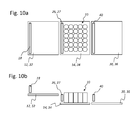
- the overthrust can also be multi-phase, namely from a first module 12 to a second module 14 and from there to a third module 30 (see. FIGS. 10 to 15 ), wherein in each case the same override principles can be used with the pushing from behind sliding beams 18 and possibly supported from the front supporting, braking or conditioning beam 26.
- the first module 12 can be formed by a grouping table 32 or a so-called layer forming belt or the like, from which a transfer of article layers 10 to a lifting and / or converting device forming the second module 14 can be provided can, for example, by an elevator 34, a lifting device or a pivotable and / or raised and lowered arm of a loading device not shown here o. The like. Can be formed.
- the adjoining third module 30 can, for example, a blind loading station o. The like.
- all modules 12, 14 and 30 can each have a web drive in the form of a suitable horizontal conveyor system. These web drives are each separately controllable, the drive speed to the feed rate of the thrust and conditioning beams 18 and 26 is tuned. Normally, the conveyor speed of the belt is less than or equal to the overthrust speed. In most cases, however, the belt speed is less than the slip speeds, as such belts are generally not designed for high speeds, as are desirable in the overthrusting operations.
- modules 12, 14 and / or 30 are used without their own rail drives, then it makes sense to make the support levels on which the article layers 10 are moved as low-friction as possible.
- wood panels or plastic panels can be used for these support levels, which may possibly have longitudinal profiles in the form of webs, ribs or grooves.
- first, second and third modules are therefore primarily to be understood as a placeholder for different handling stations, between which the closed article layers 10 are moved by means of the transfer movements shown, without causing individual articles slip, tip over or leave the article formation in any other way.
- FIGS. 5 to 15 show the upper views ( Fig. 5a . Fig. 6a etc.) are schematic plan views of the article layer 10 transferred between the modules, while the lower views ( Fig. 5b . Fig. 6b etc.) each show schematic side views of the same process phase.
- the Fig. 5 shows in two views the beginning of a Kochübterrorism the article position 10 from the grouping table 32 on the elevator 34.
- the grouping table 32 associated push bar 18 is located to the left behind the article position 10 so that it can be pushed to the right in the feed direction 38 on the elevator 34.
- the Schmidthalte- or conditioning bar 26 is located on the left edge of the support surface of the elevator 34, ready for the system to the article position 10 after their beginning transfer to the elevator 34, which in the two views of Fig. 6 is shown.
- the push beam 18 associated with the grouping table 32 pushes the article ply 10 onto the self-leveling elevator 34, while the contact beam 26 associated therewith moves in touching contact or at a short distance in front of the article ply 10.
- the feed movements of the two beams 18 and 26 are largely synchronous.
- the article position 10 was completely pushed onto the elevator 34, wherein the contact beam 26 forms a counter-holder in front of the layer 10 and this ensures the necessary delay of the transfer movement against overturning container or Article 16.
- the push bar 18 of the first module 12 or the grouping table 32 has reached its end position and is stopped while the contact beam 26 is moved to its end position at the front edge of the support surface of the elevator 34 (see. Fig. 8 ).
- the hoist of the elevator 34 can now according to Fig. 8 be lowered or raised to be adapted to the level of the third module 30 and the stacking station 36.
- the push bar 18 moves back against the conveying direction 38 of the article position 10 in its initial position, while the contact beam 26 first rests because it has fulfilled its function of stabilizing the braked article 16.
- the contact bar 26 can not be returned to the same level, but can, for example, according to Fig. 9b raised and returned in the direction of arrow above the article position 10.
- it could also be lowered and returned below the elevator 10 or brought laterally out of the engagement area with the articles 16 and displaced in a suitable manner against the feed direction 38.
- This return movement of the abutment bar 26 serves to him in the following overthrusting according to Fig. 10 to use as a push bar 27 can.
- the article layer 10 can now be pushed onto the third module 30 and the stacking station 36, where another investment beam 40 ensures the installation and stabilization of the front article 16 of the article position 10 in their overthrusting, which in the Figures 11 and 12 is shown.
- the push beam 27 of the elevator 34 which previously functioned as a contact beam 26, pushes the article position 10 from the rear in the feed direction 38 (FIG. Fig. 10 . Fig. 11 ), while the attachment bar 40 of the stacking station 36 serves as a front attachment ( Fig. 11 ).
- the two beams 27 and 40 move in this case at least in phases, together with the pushed-over article position 10 synchronously in the feed direction 38.
- the first module or the grouping table 32 is no longer shown because it / he is no longer involved in the further movement of the article cover 10 on the stacking station 36.
- the elevator 34 can be raised again or - depending on the phase of the stacking process and depending on the number of stacked article layers 10 - also lowered to be adjusted back to the level of group table 32.
- the push bar 27 can be moved back against the feed direction 38 in order subsequently to act again as an abutment bar 26 for the next article layer 10 pushed over by the first module 12 or grouping table 12.
- the two beams 40 and 42 can move synchronously and finally stop when the end position of the article layer 10 required for the stacking has been reached. Since the elevator 34 has no function in this view for the positioning of the article layer 10, he was in the representation of Fig. 15 omitted. However, the two bars 40 and 42 do not necessarily have to move synchronously. Optionally, their movements may also be controlled in a manner that the brake beam 40 is initially moved in synchronism with the push bar 27 while maintaining a certain distance from the foremost row of the article ply 10. Thereafter, shortly before reaching the end position for the brake bar 40 its speed can be reduced until it finally comes to a stop in the end position of the article position 10 before this. During this deceleration phase, the distance to the foremost row of articles of the article layer 10 is gradually reduced, so that the article position rests against the brake bar 40 at the end position (cf. Fig. 13 and Fig. 14 ).
- the drive of the respective thrust and conditioning beams can be done in different ways, eg. Via linear actuators or according to Fig. 16
- One or more beams are preferably arranged on such a chain or belt circulation, so that a rapid conveyance of the article position between the respective modules is made possible.
- the individual modules 12, 14 and 30 can optionally have their own belt drives o. The like. Movable and in the feed direction 38 or oppositely movable and drivable bearing levels, which move usefully synchronously with the moving thrust and conditioning beams, so that the article promotion in optimal Way is supported.
- the rotational speeds should be variable in the desired manner in order to be able to control the movements of the push beams 18 and contact beams 26 in such a way that the article position 10 can be displaced between the modules 12 and 14 in the feed direction 38 in accordance with their intended course of movement.
- two push bars 18 or two contact bars 26 can be moved, for example, at each of the movement paths of the Zuschantriebe 44 circulating in the arrow direction, whereby the overtravel of the article position 10 between the successive modules 12 and 14 can be controlled in the desired manner.
- the schematic representation of Fig. 17 shows a further embodiment of a second module 14, which is here as a so-called blind gripper head 46 o.
- the like Formed and can serve to implement the article layers 10 between the adjacent modules 12 and 30, for example.
- the support plane of the blind gripper head 46 typically has movable elements 48, optionally as horizontally displaceable rollers or plate segments o. The like., Which apart for settling the article position 10 in the horizontal direction can be driven, at the same time the article position 10 is held and stabilized laterally by means of the two thrust or conditioning beams 18 and 26 respectively.
- the two movable elements 48 are moved together and thereby form the support plane for supporting the article layer 10th
- the in Fig. 17 arranged on the right of the article position 10 contact beams 26 can also be moved in the manner described above in the horizontal direction so that he can fulfill its stabilizing and braking function for the article 16 when pushing the article layer 10 on the module 14 and in particular their delay, to prevent the tip of the front article 16 in the conveying direction.
- the slide bar 18 arranged on the left can also be moved along a horizontal and sectionally vertical displacement path 50 in order to be able to push the article position 10 in the feed direction 38 on the one hand.
- the push beam 18 must be brought out of the collision area with the article layer 10, which is why it can be lifted as needed in the vertical direction and thus brought out of the Matterubweg.
- the horizontal and vertical displaceability of the second module 14 or the Venetian blind head 46 is indicated by the double arrow 52.
- This may be, for example, the aforementioned lifting and / or transfer device or the blind gripper head 46 o. The like. Be.
- This transport module must be prepared accordingly to accommodate the second push or conditioning beams at least briefly until the transferred article position 10 has come to a standstill and no more products are delayed and therefore can tip over or slip.
- this or its guide elements can optionally be part of the second module 14, i. the lifting and / or transfer device or the Jalouêtreiferkopfes 46, be.
- the guide elements which are responsible for the drive and the motion control of the second thrust or installation beam, extend at least during the overshoot in this second module, which, for example, by a suitable linkage or linear drive o. Like. Can be achieved.
- FIGS. 18 to 22 illustrate in a total of twenty-three individual representations, a further embodiment of successive process steps of the transfer of an article layer 10 between three adjacent modules 12, 14 and 30.
- each illustrated on the left first module 12 is formed as in the previously described embodiments by a Gruppiersystem 60
- the an article layer 10 takes over in a predetermined formation of an upstream sorting system, not shown here.
- a sorting system can, for example, comprise one or more handling robots which form article sheets 10 which are closed from one or more article inlets and which are transferred to the first module 12 or the grouping system 60 in the manner shown.
- the Gruppiersystem 60 does not have to be adjustable in height or laterally displaceable, but may be arranged stationary, which also from the FIGS.
- the grouping system 60 may also be height adjustable In this configuration, the height-adjustable grouping system 60 may be prepared for a direct transfer of the article layers 10 to the loading station 64.
- the push beams 70 and stop bars 66 normally associated with the transfer system are to be assigned to the grouping system 60 and suitably controlled in their movements, so that the transfer system can be dispensed with, without any restrictions in the function being associated therewith.
- the presentation of the Fig. 18a shows an article position 10 located on the first module 12 or the grouping system 60, which can be displaced to the right by means of the horizontally movable first push bar 18 to a second module 14 located at the same height, as shown in FIG Fig. 18b clarified.
- the second module may for example be formed by a so-called.
- Transferston 62 which is designed to be adjustable in height to allow a transfer to a below the Gruppiersystems 60 loading station 64. This depending on the loading of an underlying pallet segment 65 adjustable in height loading station 64 forms in the illustrated embodiment, the third module 30.
- FIG. 18a to 18e illustrate the article position 10 by means of the first module 12 associated first sliding beam 18 from the first module 12 and the grouping system 60 in the horizontal direction to the right on the second module 14 and the transfer table 62, wherein the transfer table 62 associated first investment bar Stabilizes the front article of the recessed article position 10 and prevents their slipping or tilting of individual items.
- the first contact beam 66 moves approximately over the entire length of the second module 14 and the transfer table 62, as the representations of Fig. 18b to 18e clarify.
- the Fig. 18d also shows a peculiarity of this embodiment, in which the first push bar 18 is pushed beyond the grouping system 60 on the edge of the transfer table 62, before he according to Fig. 18e is withdrawn again (cf. Fig. 19 ) in order to be able to move over a further article layer 10 from the first module 12 or from the grouping system 60 to the second module 14 or to the transfer table 62.
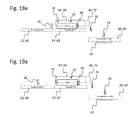
- FIGS. 18a to 18e moves the transfer table 62 associated first contact beam 66 in the horizontal direction to the right until the article position 10 according to Fig. 19a and Fig. 19b completely on the transfer table 62 and the second module 14 is pushed.
- the Fig. 19c illustrates the subsequent vertical movement of the support beam 66, which is raised to the other Overpass of the article position 10 not to hinder.
- the contact beam 66 thereby moves along a closed first movement path 68, which can be predetermined in particular by a corresponding traction mechanism drive 44.
- the presentation of the Fig. 19d illustrates the return movement of the first abutment bar 66 above the article position 10 to the left, which corresponds to Fig. 20a and Fig. 20b continues until according to Fig. 20c and Fig. 20d the initial position is reached, in which the contact beam 66 can be used to stabilize a further pushed-over article layer 10.
- FIGS. 18a to 18e the displacement of a further push beam 70 assigned to the transfer table 62 above the article position 10 along a second movement path 72 which may overlap with the first movement path 68 over long sections, but has a further traction mechanism drive 44 independent of this, since a section of the latter first movement path 68 deviating movement course is required.
- Figures 20b . 20c and 20d a displacement of the further push beam 70, which extends beyond the length of the transfer table 62 and extends partially into the region of the loading station 64 of the third module 30. This extended displacement of the further push beam 70 allows a Ausschub the article position 10 in a train from the second module 14 to the third module 30 without interrupting the overtravel is required.
- One of these Beladestation 64 associated second contact beam 74 which is at least partially moved approximately synchronously with the further push bar 70 to the right and thereby precedes the article position 10, there ensures the stabilization of the article position 10 and prevents the falling or slipping of individual items. After contacting the article situation ( Fig. 20b ) it precedes the article position 10 during its overtravel movement to the right ( Fig. 20c ), until the further push bar 70 has finished its overthrusting movement and is driven vertically upwards along the second movement path 72 in the region of the loading station 64 (FIG. Fig. 20d ).
- a third push bar 76 assigned to the loading station 64 drops vertically downwards (FIG. Fig. 21b) down to the level of article position 10 ( Fig. 21c) and then move to the right ( Fig. 21 d) to center the article layer 10 on the loading station 64 ( Fig. 21e e) , wherein at the same time the second contact beam 74 provides for the stabilization of the article layer 10.
- this is lowered down onto the pallet segment 66 ( Fig.
- Such a transfer of the article position 10 can be realized, for example, by means of a Venetian blind or plate gripper head, which can unload a complete article position 10 downwards by opening or laterally displacing its displaceable bottom.
- the further push bar 70 associated with the transfer table 62 again moves back to the left along the second path of travel 72, being moved above the level of the article layer 10 during the return movement so that it can not collide with it.
- the second contact beam 74 of the loading station 64 is also moved back in the horizontal direction to the left ( Fig. 22c ) in order to stabilize a further article layer 10 while the third push bar 76 is moved vertically upwards ( Fig. 22d ) to pass an article layer 10 carried thereunder.
- a further, not shown here variant of the stacking method may optionally provide that on the loading station 64 a plurality of article layers 10 simultaneously be filed. Due to the simultaneous handling and stacking of several article layers 10, the pallet change times can be significantly reduced. As a result, the loading station 64 acts as a kind of buffer, whereby the required times for a pallet change can be minimized.
- another variant may comprise only the grouping system 60 and the loading station 64, wherein the grouping system 60 must be adjustable in height in order to be able to compensate for the different height levels of the stacks on the loading station 64 with article layers 10.
Landscapes
- Engineering & Computer Science (AREA)
- Mechanical Engineering (AREA)
- Stacking Of Articles And Auxiliary Devices (AREA)
- Specific Conveyance Elements (AREA)
Priority Applications (1)
| Application Number | Priority Date | Filing Date | Title |
|---|---|---|---|
| SI201330035T SI2639165T2 (sl) | 2012-03-14 | 2013-01-02 | Postopek in naprava za predajo plasti artiklov med sosednjimi moduli |
Applications Claiming Priority (1)
| Application Number | Priority Date | Filing Date | Title |
|---|---|---|---|
| DE102012204013A DE102012204013A1 (de) | 2012-03-14 | 2012-03-14 | Verfahren und Vorrichtung zur Übergabe von Artikellagen zwischen benachbarten Modulen |
Publications (3)
| Publication Number | Publication Date |
|---|---|
| EP2639165A1 true EP2639165A1 (fr) | 2013-09-18 |
| EP2639165B1 EP2639165B1 (fr) | 2015-03-04 |
| EP2639165B2 EP2639165B2 (fr) | 2021-08-18 |
Family
ID=47552878
Family Applications (1)
| Application Number | Title | Priority Date | Filing Date |
|---|---|---|---|
| EP13150014.2A Active EP2639165B2 (fr) | 2012-03-14 | 2013-01-02 | Procédé et dispositif pour transférer des couches d'articles entre des modules voisines |
Country Status (6)
| Country | Link |
|---|---|
| US (1) | US9862552B2 (fr) |
| EP (1) | EP2639165B2 (fr) |
| CN (1) | CN103303668B (fr) |
| DE (1) | DE102012204013A1 (fr) |
| ES (1) | ES2536701T5 (fr) |
| SI (1) | SI2639165T2 (fr) |
Cited By (2)
| Publication number | Priority date | Publication date | Assignee | Title |
|---|---|---|---|---|
| EP2848561A1 (fr) * | 2013-09-12 | 2015-03-18 | Krones Aktiengesellschaft | Procédé et dispositif de déplacement horizontal d'emplacements d'articles entre des modules voisins |
| WO2019048219A1 (fr) * | 2017-09-05 | 2019-03-14 | Krones Aktiengesellschaft | Dispositif et procédé pour le transfert de couches palettisables sur des surfaces de support et/ou d'empilement |
Families Citing this family (21)
| Publication number | Priority date | Publication date | Assignee | Title |
|---|---|---|---|---|
| DE102013212329A1 (de) * | 2013-06-26 | 2014-12-31 | Robert Bosch Gmbh | Verpackung von biegeschlaffen Bauteilen |
| TWI593616B (zh) * | 2014-06-27 | 2017-08-01 | 巴柏斯特麥克斯合資公司 | 用於將板片元件供給至機器的方法,供給平台以及裝備該供給平台的加工機 |
| DE102014221232A1 (de) * | 2014-10-20 | 2016-04-21 | Krones Aktiengesellschaft | Vorrichtung und Verfahren zum Umgang mit Artikeln |
| DE102014223319A1 (de) * | 2014-11-14 | 2016-05-19 | Krones Aktiengesellschaft | Verfahren und Anordnung zur Beförderung von Artikeln, Stückgütern und/oder Gebinden innerhalb wenigstens zweier Förderstreckenabschnitte |
| JP6534820B2 (ja) | 2015-01-23 | 2019-06-26 | 株式会社イシダ | 押し込み機構、および、これを備える箱詰め装置 |
| KR101781151B1 (ko) | 2015-03-04 | 2017-10-23 | 주식회사 금비 | 용기 이송장치 |
| CN104724313A (zh) * | 2015-03-31 | 2015-06-24 | 成都三可实业有限公司 | 一种口香糖外包装机输糖装置 |
| US9802768B2 (en) * | 2015-10-29 | 2017-10-31 | The Procter & Gamble Company | Apparatus for reorienting and/or stacking products |
| CN105692153B (zh) * | 2016-02-18 | 2017-12-29 | 东莞工易机器人有限公司 | 用于工件固化的理料机构及使用该理料机构的理料方法 |
| DE102016225499A1 (de) * | 2016-12-19 | 2018-06-21 | Krones Aktiengesellschaft | Verfahren und Vorrichtung zum Überführen einer palettierfähigen Lage auf eine zugeordnete Palette |
| CN108313515A (zh) * | 2017-12-22 | 2018-07-24 | 南通海立电子有限公司 | 一种电容器成品收集装置 |
| US10899562B2 (en) * | 2017-12-27 | 2021-01-26 | The Procter & Gamble Company | Apparatus for transferring and/or stacking products |
| US10882705B2 (en) * | 2017-12-27 | 2021-01-05 | The Procter & Gamble Company | Method for transferring and/or stacking products |
| CN111936402A (zh) * | 2018-04-13 | 2020-11-13 | 阿自倍尔株式会社 | 输送装置 |
| DE102018214047A1 (de) * | 2018-08-21 | 2020-02-27 | Langhammer Gmbh | Palettiervorrichtung und Verfahren zum Betrieb einer Palettiervorrichtung |
| US11066246B2 (en) * | 2019-04-25 | 2021-07-20 | Siemens Logistics Llc | Extendible conveyor with irregular parcel handling |
| CN110441113B (zh) * | 2019-09-05 | 2023-11-10 | 西南石油大学 | 一种气囊挤压式自稳定堆石装置 |
| CN110606362A (zh) * | 2019-09-29 | 2019-12-24 | 深圳赛动生物自动化有限公司 | 培养瓶自动传输堆垛装置及其工作方法 |
| CN111361952A (zh) * | 2020-03-23 | 2020-07-03 | 西安工业大学 | 一种异型硅钢片自动码垛生产线 |
| US11731842B2 (en) * | 2021-09-13 | 2023-08-22 | The Procter & Gamble Company | Bypass carton accumulator |
| CN115027741B (zh) * | 2022-08-11 | 2022-11-15 | 湖南世容纸塑包装有限公司 | 一种纸杯包装机的输送装置 |
Citations (9)
| Publication number | Priority date | Publication date | Assignee | Title |
|---|---|---|---|---|
| GB1150300A (en) * | 1967-02-15 | 1969-04-30 | E C C Quarries Ltd | Pallet Loading Machine. |
| FR2259750A1 (en) * | 1974-01-31 | 1975-08-29 | Pont A Mousson | Tray loading installation for tins - has overlying platforms for groups of tins and trays |
| US4055257A (en) * | 1976-05-04 | 1977-10-25 | Molins Machine Company, Inc. | Stacking apparatus |
| US4934509A (en) * | 1987-01-27 | 1990-06-19 | SAPAL--Societe Anonyme des Plieusus Automatiques | Device for transferring products transported by a conveyor and methods of using said device |
| DE4117434A1 (de) | 1991-05-28 | 1992-12-03 | Winkler Duennebier Kg Masch | Verfahren und vorrichtung zum stapeln |
| DE4207725A1 (de) * | 1992-03-11 | 1993-09-23 | Kisters Maschinenbau Gmbh | Verfahren und vorrichtung zum verpacken von gegenstaenden in einem kontinuierlich ablaufenden prozess |
| DE4435981A1 (de) | 1994-10-08 | 1996-04-11 | Buehler Optima Maschf | Einrichtung zum Zuführen von zu verpackenden Produkten zu einer Verpackungsmaschine |
| DE60307332T2 (de) | 2002-01-22 | 2007-04-12 | Ishida Co., Ltd. | Vorrichtung zum Transportieren und Einschachteln einer Gruppe von Gegenständen |
| WO2010100545A2 (fr) * | 2009-03-05 | 2010-09-10 | Eurosicma S.P.A. | Installation permettant d'alimenter une machine de conditionnement en groupes de produits |
Family Cites Families (28)
| Publication number | Priority date | Publication date | Assignee | Title |
|---|---|---|---|---|
| GB1055611A (en) * | 1964-09-08 | 1967-01-18 | Metal Box Co Ltd | Improvements in or relating to apparatus for loading articles in rows on a supporting base |
| CH664127A5 (de) | 1984-07-31 | 1988-02-15 | Sig Schweiz Industrieges | Vorrichtung zum abtrennen von gruppen bestimmter laenge von einem stapel kontinuierlich zugefuehrter gegenstaende. |
| US4978275A (en) * | 1989-07-31 | 1990-12-18 | Simplimatic Engineering Company | Computer controlled article handling device |
| US5271709A (en) * | 1992-07-22 | 1993-12-21 | Goldco Industries, Inc. | Device and method for repeatedly forming a preselected arrangement of conveyed articles |
| US5310307A (en) * | 1993-02-12 | 1994-05-10 | Goldco Industries, Inc. | Depalletizing device and method |
| GB9421177D0 (en) * | 1994-10-20 | 1994-12-07 | Riverwood Int Ltd | Spacing conveyor mechanism |
| US5699651A (en) * | 1996-05-23 | 1997-12-23 | Riverwood International Corporation | Selector assembly |
| US5893701A (en) * | 1996-06-13 | 1999-04-13 | Food Machinery Sales, Inc. | Method and apparatus for forming groups of work products |
| US5758471A (en) * | 1996-11-05 | 1998-06-02 | Lantech, Inc. | Load building and wrapping apparatus |
| IT1309297B1 (it) * | 1999-06-22 | 2002-01-22 | Gd Spa | Convogliatore a tasche. |
| DE19958019C2 (de) † | 1999-12-02 | 2003-10-02 | Seidel Helmut | Verfahren und Vorrichtung zum kontrollierten Übernehmen eines Gegenstandes, insbesondere einer teilweise oder vollständig gebildeten Faltschachtel |
| US6182814B1 (en) † | 2000-03-03 | 2001-02-06 | Sig Pack, Inc., Doboy Division | Inline vacuum slug feeder |
| JP2001315998A (ja) * | 2000-05-12 | 2001-11-13 | Nec Corp | 搬送間隔調整方法および装置 |
| DE10048007A1 (de) * | 2000-09-26 | 2002-04-11 | Iwk Verpackungstechnik Gmbh | Verfahren und Vorrichtung zur Übergabe eines Produktes in einer Verpackungsmaschine |
| ATE327959T1 (de) * | 2001-07-05 | 2006-06-15 | Grapha Holding Ag | Einrichtung zum transport von auf einer auflage in einem stapel aufeinanderliegenden druckprodukten |
| US6843360B2 (en) * | 2002-03-27 | 2005-01-18 | Douglas Machine, Inc. | Retractable transfer device metering apparatus and methods |
| ITBO20020460A1 (it) * | 2002-07-18 | 2004-01-19 | Aetna Group Spa | Dispositivo per la separazione di gruppi di prodotti alimentati in continuo |
| DE10347540B4 (de) * | 2003-10-09 | 2009-06-10 | Khs Ag | Abteil-, Synchronisations- und Verdichtungsvorrichtung |
| DE102005026639B4 (de) * | 2005-06-09 | 2009-01-08 | Khs Ag | Vorrichtung zum Aufteilen, Eintakten und Gruppieren von Stückgütern |
| DE102005051027B4 (de) † | 2005-10-25 | 2008-10-02 | Meurer, Franz-Josef | Einrichtung und Verfahren zum Einschlagen eines Gebindes in Folie |
| DE102006045453A1 (de) * | 2006-09-26 | 2008-04-03 | Khs Ag | Transportsystem |
| DE102006049801A1 (de) * | 2006-10-23 | 2008-04-24 | Iwk Verpackungstechnik Gmbh | Verfahren zur Steuerung der Übergabe eines Produktstapels in einer Verpackungsmaschine |
| DE102006054469B3 (de) † | 2006-11-18 | 2007-12-20 | Franz-Josef Meurer | Einrichtung und Verfahren zum Einschlagen eines Gebindes in Folie |
| ES2328954T3 (es) * | 2006-12-14 | 2009-11-19 | TETRA LAVAL HOLDINGS & FINANCE SA | Unidad para agrupar paquetes a lo largo de una trayectoria de transferencia. |
| DE102007038827A1 (de) * | 2007-08-16 | 2009-02-26 | Khs Ag | Vorrichtung zur Bildung von Produktgruppen |
| EP2276686B1 (fr) * | 2008-03-31 | 2012-10-31 | Douglas Machine, Inc. | Appareil et procédés de mesure de dispositif de transfert souple rétractable |
| JP5302039B2 (ja) * | 2009-02-16 | 2013-10-02 | 株式会社イシダ | 箱詰め装置 |
| IT1398557B1 (it) † | 2010-03-09 | 2013-03-01 | Eurosicma S P A | Impianto per la formazione e il trasferimento continuo sincronizzato di gruppi compatti di prodotti accostati fra loro lungo il percorso di trasferimento. |
-
2012
- 2012-03-14 DE DE102012204013A patent/DE102012204013A1/de active Pending
-
2013
- 2013-01-02 EP EP13150014.2A patent/EP2639165B2/fr active Active
- 2013-01-02 SI SI201330035T patent/SI2639165T2/sl unknown
- 2013-01-02 ES ES13150014T patent/ES2536701T5/es active Active
- 2013-01-29 CN CN201310034343.5A patent/CN103303668B/zh active Active
- 2013-03-06 US US13/787,071 patent/US9862552B2/en active Active
Patent Citations (9)
| Publication number | Priority date | Publication date | Assignee | Title |
|---|---|---|---|---|
| GB1150300A (en) * | 1967-02-15 | 1969-04-30 | E C C Quarries Ltd | Pallet Loading Machine. |
| FR2259750A1 (en) * | 1974-01-31 | 1975-08-29 | Pont A Mousson | Tray loading installation for tins - has overlying platforms for groups of tins and trays |
| US4055257A (en) * | 1976-05-04 | 1977-10-25 | Molins Machine Company, Inc. | Stacking apparatus |
| US4934509A (en) * | 1987-01-27 | 1990-06-19 | SAPAL--Societe Anonyme des Plieusus Automatiques | Device for transferring products transported by a conveyor and methods of using said device |
| DE4117434A1 (de) | 1991-05-28 | 1992-12-03 | Winkler Duennebier Kg Masch | Verfahren und vorrichtung zum stapeln |
| DE4207725A1 (de) * | 1992-03-11 | 1993-09-23 | Kisters Maschinenbau Gmbh | Verfahren und vorrichtung zum verpacken von gegenstaenden in einem kontinuierlich ablaufenden prozess |
| DE4435981A1 (de) | 1994-10-08 | 1996-04-11 | Buehler Optima Maschf | Einrichtung zum Zuführen von zu verpackenden Produkten zu einer Verpackungsmaschine |
| DE60307332T2 (de) | 2002-01-22 | 2007-04-12 | Ishida Co., Ltd. | Vorrichtung zum Transportieren und Einschachteln einer Gruppe von Gegenständen |
| WO2010100545A2 (fr) * | 2009-03-05 | 2010-09-10 | Eurosicma S.P.A. | Installation permettant d'alimenter une machine de conditionnement en groupes de produits |
Cited By (4)
| Publication number | Priority date | Publication date | Assignee | Title |
|---|---|---|---|---|
| EP2848561A1 (fr) * | 2013-09-12 | 2015-03-18 | Krones Aktiengesellschaft | Procédé et dispositif de déplacement horizontal d'emplacements d'articles entre des modules voisins |
| CN104512715A (zh) * | 2013-09-12 | 2015-04-15 | 克罗内斯股份公司 | 使相邻传送单元之间的物品层水平移动的装置和方法 |
| US9290332B2 (en) | 2013-09-12 | 2016-03-22 | Krones Ag | Device and method for horizontal movement of layers of articles between adjacent conveyor modules |
| WO2019048219A1 (fr) * | 2017-09-05 | 2019-03-14 | Krones Aktiengesellschaft | Dispositif et procédé pour le transfert de couches palettisables sur des surfaces de support et/ou d'empilement |
Also Published As
| Publication number | Publication date |
|---|---|
| ES2536701T3 (es) | 2015-05-27 |
| CN103303668B (zh) | 2016-03-16 |
| CN103303668A (zh) | 2013-09-18 |
| DE102012204013A1 (de) | 2013-09-19 |
| SI2639165T2 (sl) | 2022-01-31 |
| SI2639165T1 (sl) | 2015-07-31 |
| EP2639165B1 (fr) | 2015-03-04 |
| US20130243558A1 (en) | 2013-09-19 |
| US9862552B2 (en) | 2018-01-09 |
| EP2639165B2 (fr) | 2021-08-18 |
| ES2536701T5 (es) | 2022-03-02 |
Similar Documents
| Publication | Publication Date | Title |
|---|---|---|
| EP2639165B1 (fr) | Procédé et dispositif pour transférer des couches d'articles entre des modules voisins | |
| EP2825490B1 (fr) | Procédé pour transférer des couches d' articles entre des modules voisines | |
| EP2848561B1 (fr) | Procédé et dispositif de déplacement horizontal d'emplacements d'articles entre des modules voisins | |
| EP2825488B1 (fr) | Procédé et dispositif servant à transférer de manière horizontale des couches d'articles entre des modules adjacents | |
| DE1786486C3 (de) | Vorrichtung zum Sammeln und Be fordern einer Gruppe von Verpackungs einheiten, beispielsweise Flaschen, Dosen u dgl in eine Station zum gruppen weisen Einhüllen solcher Verpackungs einheiten in Verpackungsmaterial Ausscheidung aus 1561939 | |
| EP3218290B1 (fr) | Procédé et agencement pour le transport d'objets, de colis de détail et/ou de fûts dans au moins deux sections de voie de transport | |
| EP2848562B1 (fr) | Procédé et dispositif de déplacement horizontal d'articles entre des modules voisins | |
| EP3877308B1 (fr) | Dispositif de regroupement de contenants | |
| EP2881347A1 (fr) | Dispositif de palettisation et son procédé de fonctionnement | |
| EP3406549B1 (fr) | Dispositif et procédé de transfert d'au moins une couche palettisable sur une surface d'empilement | |
| DE102011088849B4 (de) | Verfahren und Vorrichtung zum Palettieren von Artikellagen auf einem Stapelplatz | |
| EP2832667B1 (fr) | Procédé et dispositif d'empilement et/ou de palettisation de couches de paquets ou de pièces | |
| WO2019048219A1 (fr) | Dispositif et procédé pour le transfert de couches palettisables sur des surfaces de support et/ou d'empilement | |
| EP0291083B1 (fr) | Procédé et installation pour transférer des plates-formes de transport sur une table élévatrice d'un station d'empilage | |
| EP3129311B1 (fr) | Procédé permettant de déplacer horizontalement des groupes d'articles | |
| EP2093166B1 (fr) | Procedé pour le déstockage rapide des articles d'un magasin de stockage et un magasin de stockage correspondant | |
| DE69602664T2 (de) | Vorrichtung zum Bilden von Gruppen von Gegenständen in Kartoniermaschinen oder dergleichen | |
| WO2010089150A1 (fr) | Poste de déchargement pour la séparation automatisée d'un emballage et d'un auxiliaire de chargement | |
| EP2689664B1 (fr) | Procédé et installation pour la réception limitée dans le temps de supports de produits cuits | |
| EP4276021A1 (fr) | Machine d'emballage dotée d'un dispositif de regroupement et procédé de production de groupes monocouche de produits se chevauchant partiellement | |
| WO2020001800A1 (fr) | Dispositif de manipulation et/ou de d'emballage et procédé pour emballer des articles | |
| DE3827063A1 (de) | Verfahren und einrichtung zum gruppenweisen stapeln von stapelelementen | |
| DE2520716A1 (de) | Stapelvorrichtung zum stapeln von fliesenrohlingen | |
| WO2019076708A1 (fr) | Procédé et dispositif de manipulation et/ou de regroupement de marchandises de détail | |
| DE3816448A1 (de) | Verfahren und anlage zum ueberfuehren von transportplattformen auf den hubtisch einer stapelstation |
Legal Events
| Date | Code | Title | Description |
|---|---|---|---|
| PUAI | Public reference made under article 153(3) epc to a published international application that has entered the european phase |
Free format text: ORIGINAL CODE: 0009012 |
|
| AK | Designated contracting states |
Kind code of ref document: A1 Designated state(s): AL AT BE BG CH CY CZ DE DK EE ES FI FR GB GR HR HU IE IS IT LI LT LU LV MC MK MT NL NO PL PT RO RS SE SI SK SM TR |
|
| AX | Request for extension of the european patent |
Extension state: BA ME |
|
| 17P | Request for examination filed |
Effective date: 20140307 |
|
| RBV | Designated contracting states (corrected) |
Designated state(s): AL AT BE BG CH CY CZ DE DK EE ES FI FR GB GR HR HU IE IS IT LI LT LU LV MC MK MT NL NO PL PT RO RS SE SI SK SM TR |
|
| 17Q | First examination report despatched |
Effective date: 20140718 |
|
| GRAP | Despatch of communication of intention to grant a patent |
Free format text: ORIGINAL CODE: EPIDOSNIGR1 |
|
| INTG | Intention to grant announced |
Effective date: 20140919 |
|
| GRAS | Grant fee paid |
Free format text: ORIGINAL CODE: EPIDOSNIGR3 |
|
| GRAA | (expected) grant |
Free format text: ORIGINAL CODE: 0009210 |
|
| STAA | Information on the status of an ep patent application or granted ep patent |
Free format text: STATUS: THE PATENT HAS BEEN GRANTED |
|
| AK | Designated contracting states |
Kind code of ref document: B1 Designated state(s): AL AT BE BG CH CY CZ DE DK EE ES FI FR GB GR HR HU IE IS IT LI LT LU LV MC MK MT NL NO PL PT RO RS SE SI SK SM TR |
|
| REG | Reference to a national code |
Ref country code: GB Ref legal event code: FG4D Free format text: NOT ENGLISH |
|
| REG | Reference to a national code |
Ref country code: CH Ref legal event code: EP |
|
| REG | Reference to a national code |
Ref country code: IE Ref legal event code: FG4D Free format text: LANGUAGE OF EP DOCUMENT: GERMAN |
|
| REG | Reference to a national code |
Ref country code: AT Ref legal event code: REF Ref document number: 713621 Country of ref document: AT Kind code of ref document: T Effective date: 20150415 |
|
| REG | Reference to a national code |
Ref country code: DE Ref legal event code: R096 Ref document number: 502013000381 Country of ref document: DE Effective date: 20150416 |
|
| REG | Reference to a national code |
Ref country code: ES Ref legal event code: FG2A Ref document number: 2536701 Country of ref document: ES Kind code of ref document: T3 Effective date: 20150527 |
|
| REG | Reference to a national code |
Ref country code: NL Ref legal event code: T3 |
|
| PG25 | Lapsed in a contracting state [announced via postgrant information from national office to epo] |
Ref country code: LT Free format text: LAPSE BECAUSE OF FAILURE TO SUBMIT A TRANSLATION OF THE DESCRIPTION OR TO PAY THE FEE WITHIN THE PRESCRIBED TIME-LIMIT Effective date: 20150304 Ref country code: SE Free format text: LAPSE BECAUSE OF FAILURE TO SUBMIT A TRANSLATION OF THE DESCRIPTION OR TO PAY THE FEE WITHIN THE PRESCRIBED TIME-LIMIT Effective date: 20150304 Ref country code: HR Free format text: LAPSE BECAUSE OF FAILURE TO SUBMIT A TRANSLATION OF THE DESCRIPTION OR TO PAY THE FEE WITHIN THE PRESCRIBED TIME-LIMIT Effective date: 20150304 Ref country code: FI Free format text: LAPSE BECAUSE OF FAILURE TO SUBMIT A TRANSLATION OF THE DESCRIPTION OR TO PAY THE FEE WITHIN THE PRESCRIBED TIME-LIMIT Effective date: 20150304 Ref country code: NO Free format text: LAPSE BECAUSE OF FAILURE TO SUBMIT A TRANSLATION OF THE DESCRIPTION OR TO PAY THE FEE WITHIN THE PRESCRIBED TIME-LIMIT Effective date: 20150604 |
|
| REG | Reference to a national code |
Ref country code: LT Ref legal event code: MG4D |
|
| PG25 | Lapsed in a contracting state [announced via postgrant information from national office to epo] |
Ref country code: LV Free format text: LAPSE BECAUSE OF FAILURE TO SUBMIT A TRANSLATION OF THE DESCRIPTION OR TO PAY THE FEE WITHIN THE PRESCRIBED TIME-LIMIT Effective date: 20150304 Ref country code: GR Free format text: LAPSE BECAUSE OF FAILURE TO SUBMIT A TRANSLATION OF THE DESCRIPTION OR TO PAY THE FEE WITHIN THE PRESCRIBED TIME-LIMIT Effective date: 20150605 Ref country code: RS Free format text: LAPSE BECAUSE OF FAILURE TO SUBMIT A TRANSLATION OF THE DESCRIPTION OR TO PAY THE FEE WITHIN THE PRESCRIBED TIME-LIMIT Effective date: 20150304 |
|
| PG25 | Lapsed in a contracting state [announced via postgrant information from national office to epo] |
Ref country code: RO Free format text: LAPSE BECAUSE OF FAILURE TO SUBMIT A TRANSLATION OF THE DESCRIPTION OR TO PAY THE FEE WITHIN THE PRESCRIBED TIME-LIMIT Effective date: 20150304 Ref country code: SK Free format text: LAPSE BECAUSE OF FAILURE TO SUBMIT A TRANSLATION OF THE DESCRIPTION OR TO PAY THE FEE WITHIN THE PRESCRIBED TIME-LIMIT Effective date: 20150304 Ref country code: EE Free format text: LAPSE BECAUSE OF FAILURE TO SUBMIT A TRANSLATION OF THE DESCRIPTION OR TO PAY THE FEE WITHIN THE PRESCRIBED TIME-LIMIT Effective date: 20150304 Ref country code: CZ Free format text: LAPSE BECAUSE OF FAILURE TO SUBMIT A TRANSLATION OF THE DESCRIPTION OR TO PAY THE FEE WITHIN THE PRESCRIBED TIME-LIMIT Effective date: 20150304 Ref country code: PT Free format text: LAPSE BECAUSE OF FAILURE TO SUBMIT A TRANSLATION OF THE DESCRIPTION OR TO PAY THE FEE WITHIN THE PRESCRIBED TIME-LIMIT Effective date: 20150706 |
|
| PG25 | Lapsed in a contracting state [announced via postgrant information from national office to epo] |
Ref country code: IS Free format text: LAPSE BECAUSE OF FAILURE TO SUBMIT A TRANSLATION OF THE DESCRIPTION OR TO PAY THE FEE WITHIN THE PRESCRIBED TIME-LIMIT Effective date: 20150704 Ref country code: PL Free format text: LAPSE BECAUSE OF FAILURE TO SUBMIT A TRANSLATION OF THE DESCRIPTION OR TO PAY THE FEE WITHIN THE PRESCRIBED TIME-LIMIT Effective date: 20150304 |
|
| REG | Reference to a national code |
Ref country code: DE Ref legal event code: R026 Ref document number: 502013000381 Country of ref document: DE |
|
| REG | Reference to a national code |
Ref country code: FR Ref legal event code: PLFP Year of fee payment: 4 |
|
| PLBI | Opposition filed |
Free format text: ORIGINAL CODE: 0009260 |
|
| PLAX | Notice of opposition and request to file observation + time limit sent |
Free format text: ORIGINAL CODE: EPIDOSNOBS2 |
|
| 26 | Opposition filed |
Opponent name: MEURER VERPACKUNGSSYSTEME GMBH Effective date: 20151202 |
|
| PG25 | Lapsed in a contracting state [announced via postgrant information from national office to epo] |
Ref country code: DK Free format text: LAPSE BECAUSE OF FAILURE TO SUBMIT A TRANSLATION OF THE DESCRIPTION OR TO PAY THE FEE WITHIN THE PRESCRIBED TIME-LIMIT Effective date: 20150304 |
|
| PLBB | Reply of patent proprietor to notice(s) of opposition received |
Free format text: ORIGINAL CODE: EPIDOSNOBS3 |
|
| PG25 | Lapsed in a contracting state [announced via postgrant information from national office to epo] |
Ref country code: LU Free format text: LAPSE BECAUSE OF FAILURE TO SUBMIT A TRANSLATION OF THE DESCRIPTION OR TO PAY THE FEE WITHIN THE PRESCRIBED TIME-LIMIT Effective date: 20160102 |
|
| REG | Reference to a national code |
Ref country code: CH Ref legal event code: PL |
|
| PG25 | Lapsed in a contracting state [announced via postgrant information from national office to epo] |
Ref country code: MC Free format text: LAPSE BECAUSE OF FAILURE TO SUBMIT A TRANSLATION OF THE DESCRIPTION OR TO PAY THE FEE WITHIN THE PRESCRIBED TIME-LIMIT Effective date: 20150304 |
|
| PG25 | Lapsed in a contracting state [announced via postgrant information from national office to epo] |
Ref country code: LI Free format text: LAPSE BECAUSE OF NON-PAYMENT OF DUE FEES Effective date: 20160131 Ref country code: CH Free format text: LAPSE BECAUSE OF NON-PAYMENT OF DUE FEES Effective date: 20160131 |
|
| REG | Reference to a national code |
Ref country code: IE Ref legal event code: MM4A |
|
| REG | Reference to a national code |
Ref country code: FR Ref legal event code: PLFP Year of fee payment: 5 |
|
| PG25 | Lapsed in a contracting state [announced via postgrant information from national office to epo] |
Ref country code: IE Free format text: LAPSE BECAUSE OF NON-PAYMENT OF DUE FEES Effective date: 20160102 |
|
| PLAB | Opposition data, opponent's data or that of the opponent's representative modified |
Free format text: ORIGINAL CODE: 0009299OPPO |
|
| PLAB | Opposition data, opponent's data or that of the opponent's representative modified |
Free format text: ORIGINAL CODE: 0009299OPPO |
|
| R26 | Opposition filed (corrected) |
Opponent name: MEURER VERPACKUNGSSYSTEME GMBH Effective date: 20151202 |
|
| R26 | Opposition filed (corrected) |
Opponent name: MEURER VERPACKUNGSSYSTEME GMBH Effective date: 20151202 |
|
| PG25 | Lapsed in a contracting state [announced via postgrant information from national office to epo] |
Ref country code: MT Free format text: LAPSE BECAUSE OF FAILURE TO SUBMIT A TRANSLATION OF THE DESCRIPTION OR TO PAY THE FEE WITHIN THE PRESCRIBED TIME-LIMIT Effective date: 20150304 |
|
| GBPC | Gb: european patent ceased through non-payment of renewal fee |
Effective date: 20170102 |
|
| PG25 | Lapsed in a contracting state [announced via postgrant information from national office to epo] |
Ref country code: GB Free format text: LAPSE BECAUSE OF NON-PAYMENT OF DUE FEES Effective date: 20170102 |
|
| REG | Reference to a national code |
Ref country code: FR Ref legal event code: PLFP Year of fee payment: 6 |
|
| PG25 | Lapsed in a contracting state [announced via postgrant information from national office to epo] |
Ref country code: CY Free format text: LAPSE BECAUSE OF FAILURE TO SUBMIT A TRANSLATION OF THE DESCRIPTION OR TO PAY THE FEE WITHIN THE PRESCRIBED TIME-LIMIT Effective date: 20150304 Ref country code: SM Free format text: LAPSE BECAUSE OF FAILURE TO SUBMIT A TRANSLATION OF THE DESCRIPTION OR TO PAY THE FEE WITHIN THE PRESCRIBED TIME-LIMIT Effective date: 20150304 Ref country code: HU Free format text: LAPSE BECAUSE OF FAILURE TO SUBMIT A TRANSLATION OF THE DESCRIPTION OR TO PAY THE FEE WITHIN THE PRESCRIBED TIME-LIMIT; INVALID AB INITIO Effective date: 20130102 |
|
| PG25 | Lapsed in a contracting state [announced via postgrant information from national office to epo] |
Ref country code: MK Free format text: LAPSE BECAUSE OF FAILURE TO SUBMIT A TRANSLATION OF THE DESCRIPTION OR TO PAY THE FEE WITHIN THE PRESCRIBED TIME-LIMIT Effective date: 20150304 Ref country code: TR Free format text: LAPSE BECAUSE OF FAILURE TO SUBMIT A TRANSLATION OF THE DESCRIPTION OR TO PAY THE FEE WITHIN THE PRESCRIBED TIME-LIMIT Effective date: 20150304 |
|
| APAH | Appeal reference modified |
Free format text: ORIGINAL CODE: EPIDOSCREFNO |
|
| APBM | Appeal reference recorded |
Free format text: ORIGINAL CODE: EPIDOSNREFNO |
|
| APBP | Date of receipt of notice of appeal recorded |
Free format text: ORIGINAL CODE: EPIDOSNNOA2O |
|
| PG25 | Lapsed in a contracting state [announced via postgrant information from national office to epo] |
Ref country code: BG Free format text: LAPSE BECAUSE OF FAILURE TO SUBMIT A TRANSLATION OF THE DESCRIPTION OR TO PAY THE FEE WITHIN THE PRESCRIBED TIME-LIMIT Effective date: 20150304 |
|
| APBQ | Date of receipt of statement of grounds of appeal recorded |
Free format text: ORIGINAL CODE: EPIDOSNNOA3O |
|
| PG25 | Lapsed in a contracting state [announced via postgrant information from national office to epo] |
Ref country code: AL Free format text: LAPSE BECAUSE OF FAILURE TO SUBMIT A TRANSLATION OF THE DESCRIPTION OR TO PAY THE FEE WITHIN THE PRESCRIBED TIME-LIMIT Effective date: 20150304 |
|
| APBU | Appeal procedure closed |
Free format text: ORIGINAL CODE: EPIDOSNNOA9O |
|
| PUAH | Patent maintained in amended form |
Free format text: ORIGINAL CODE: 0009272 |
|
| STAA | Information on the status of an ep patent application or granted ep patent |
Free format text: STATUS: PATENT MAINTAINED AS AMENDED |
|
| 27A | Patent maintained in amended form |
Effective date: 20210818 |
|
| AK | Designated contracting states |
Kind code of ref document: B2 Designated state(s): AL AT BE BG CH CY CZ DE DK EE ES FI FR GB GR HR HU IE IS IT LI LT LU LV MC MK MT NL NO PL PT RO RS SE SI SK SM TR |
|
| REG | Reference to a national code |
Ref country code: DE Ref legal event code: R102 Ref document number: 502013000381 Country of ref document: DE |
|
| REG | Reference to a national code |
Ref country code: NL Ref legal event code: FP |
|
| REG | Reference to a national code |
Ref country code: ES Ref legal event code: DC2A Ref document number: 2536701 Country of ref document: ES Kind code of ref document: T5 Effective date: 20220302 |
|
| P01 | Opt-out of the competence of the unified patent court (upc) registered |
Effective date: 20230523 |
|
| PGFP | Annual fee paid to national office [announced via postgrant information from national office to epo] |
Ref country code: NL Payment date: 20231215 Year of fee payment: 12 Ref country code: FR Payment date: 20231212 Year of fee payment: 12 |
|
| PGFP | Annual fee paid to national office [announced via postgrant information from national office to epo] |
Ref country code: BE Payment date: 20231219 Year of fee payment: 12 |
|
| PGFP | Annual fee paid to national office [announced via postgrant information from national office to epo] |
Ref country code: ES Payment date: 20240205 Year of fee payment: 12 |
|
| PGFP | Annual fee paid to national office [announced via postgrant information from national office to epo] |
Ref country code: AT Payment date: 20231227 Year of fee payment: 12 |
|
| PGFP | Annual fee paid to national office [announced via postgrant information from national office to epo] |
Ref country code: DE Payment date: 20231205 Year of fee payment: 12 |
|
| PGFP | Annual fee paid to national office [announced via postgrant information from national office to epo] |
Ref country code: SI Payment date: 20231221 Year of fee payment: 12 |
|
| PGFP | Annual fee paid to national office [announced via postgrant information from national office to epo] |
Ref country code: IT Payment date: 20231212 Year of fee payment: 12 |