EP2848417B1 - Behälterbehandlungsmaschine zur Bedruckung von Behältern - Google Patents
Behälterbehandlungsmaschine zur Bedruckung von Behältern Download PDFInfo
- Publication number
- EP2848417B1 EP2848417B1 EP14178479.3A EP14178479A EP2848417B1 EP 2848417 B1 EP2848417 B1 EP 2848417B1 EP 14178479 A EP14178479 A EP 14178479A EP 2848417 B1 EP2848417 B1 EP 2848417B1
- Authority
- EP
- European Patent Office
- Prior art keywords
- treatment machine
- container
- container treatment
- curing
- curing unit
- Prior art date
- Legal status (The legal status is an assumption and is not a legal conclusion. Google has not performed a legal analysis and makes no representation as to the accuracy of the status listed.)
- Active
Links
Images


Classifications
-
- B—PERFORMING OPERATIONS; TRANSPORTING
- B41—PRINTING; LINING MACHINES; TYPEWRITERS; STAMPS
- B41J—TYPEWRITERS; SELECTIVE PRINTING MECHANISMS, i.e. MECHANISMS PRINTING OTHERWISE THAN FROM A FORME; CORRECTION OF TYPOGRAPHICAL ERRORS
- B41J3/00—Typewriters or selective printing or marking mechanisms characterised by the purpose for which they are constructed
- B41J3/407—Typewriters or selective printing or marking mechanisms characterised by the purpose for which they are constructed for marking on special material
- B41J3/4073—Printing on three-dimensional objects not being in sheet or web form, e.g. spherical or cubic objects
- B41J3/40733—Printing on cylindrical or rotationally symmetrical objects, e. g. on bottles
-
- B—PERFORMING OPERATIONS; TRANSPORTING
- B41—PRINTING; LINING MACHINES; TYPEWRITERS; STAMPS
- B41F—PRINTING MACHINES OR PRESSES
- B41F17/00—Printing apparatus or machines of special types or for particular purposes, not otherwise provided for
- B41F17/006—Printing apparatus or machines of special types or for particular purposes, not otherwise provided for for printing on curved surfaces not otherwise provided for
-
- B—PERFORMING OPERATIONS; TRANSPORTING
- B41—PRINTING; LINING MACHINES; TYPEWRITERS; STAMPS
- B41F—PRINTING MACHINES OR PRESSES
- B41F17/00—Printing apparatus or machines of special types or for particular purposes, not otherwise provided for
- B41F17/08—Printing apparatus or machines of special types or for particular purposes, not otherwise provided for for printing on filamentary or elongated articles, or on articles with cylindrical surfaces
- B41F17/14—Printing apparatus or machines of special types or for particular purposes, not otherwise provided for for printing on filamentary or elongated articles, or on articles with cylindrical surfaces on articles of finite length
- B41F17/18—Printing apparatus or machines of special types or for particular purposes, not otherwise provided for for printing on filamentary or elongated articles, or on articles with cylindrical surfaces on articles of finite length on curved surfaces of articles of varying cross-section, e.g. bottles, lamp glasses
-
- B—PERFORMING OPERATIONS; TRANSPORTING
- B41—PRINTING; LINING MACHINES; TYPEWRITERS; STAMPS
- B41F—PRINTING MACHINES OR PRESSES
- B41F17/00—Printing apparatus or machines of special types or for particular purposes, not otherwise provided for
- B41F17/28—Printing apparatus or machines of special types or for particular purposes, not otherwise provided for for printing on curved surfaces of conical or frusto-conical articles
-
- B—PERFORMING OPERATIONS; TRANSPORTING
- B41—PRINTING; LINING MACHINES; TYPEWRITERS; STAMPS
- B41F—PRINTING MACHINES OR PRESSES
- B41F17/00—Printing apparatus or machines of special types or for particular purposes, not otherwise provided for
- B41F17/30—Printing apparatus or machines of special types or for particular purposes, not otherwise provided for for printing on curved surfaces of essentially spherical, or part-spherical, articles
-
- B—PERFORMING OPERATIONS; TRANSPORTING
- B41—PRINTING; LINING MACHINES; TYPEWRITERS; STAMPS
- B41J—TYPEWRITERS; SELECTIVE PRINTING MECHANISMS, i.e. MECHANISMS PRINTING OTHERWISE THAN FROM A FORME; CORRECTION OF TYPOGRAPHICAL ERRORS
- B41J11/00—Devices or arrangements of selective printing mechanisms, e.g. ink-jet printers or thermal printers, for supporting or handling copy material in sheet or web form
- B41J11/0015—Devices or arrangements of selective printing mechanisms, e.g. ink-jet printers or thermal printers, for supporting or handling copy material in sheet or web form for treating before, during or after printing or for uniform coating or laminating the copy material before or after printing
- B41J11/002—Curing or drying the ink on the copy materials, e.g. by heating or irradiating
- B41J11/0021—Curing or drying the ink on the copy materials, e.g. by heating or irradiating using irradiation
- B41J11/00214—Curing or drying the ink on the copy materials, e.g. by heating or irradiating using irradiation using UV radiation
-
- B—PERFORMING OPERATIONS; TRANSPORTING
- B41—PRINTING; LINING MACHINES; TYPEWRITERS; STAMPS
- B41J—TYPEWRITERS; SELECTIVE PRINTING MECHANISMS, i.e. MECHANISMS PRINTING OTHERWISE THAN FROM A FORME; CORRECTION OF TYPOGRAPHICAL ERRORS
- B41J2/00—Typewriters or selective printing mechanisms characterised by the printing or marking process for which they are designed
- B41J2/005—Typewriters or selective printing mechanisms characterised by the printing or marking process for which they are designed characterised by bringing liquid or particles selectively into contact with a printing material
- B41J2/01—Ink jet
- B41J2/135—Nozzles
- B41J2/165—Prevention or detection of nozzle clogging, e.g. cleaning, capping or moistening for nozzles
-
- B—PERFORMING OPERATIONS; TRANSPORTING
- B41—PRINTING; LINING MACHINES; TYPEWRITERS; STAMPS
- B41J—TYPEWRITERS; SELECTIVE PRINTING MECHANISMS, i.e. MECHANISMS PRINTING OTHERWISE THAN FROM A FORME; CORRECTION OF TYPOGRAPHICAL ERRORS
- B41J3/00—Typewriters or selective printing or marking mechanisms characterised by the purpose for which they are constructed
- B41J3/407—Typewriters or selective printing or marking mechanisms characterised by the purpose for which they are constructed for marking on special material
- B41J3/4073—Printing on three-dimensional objects not being in sheet or web form, e.g. spherical or cubic objects
-
- B—PERFORMING OPERATIONS; TRANSPORTING
- B41—PRINTING; LINING MACHINES; TYPEWRITERS; STAMPS
- B41P—INDEXING SCHEME RELATING TO PRINTING, LINING MACHINES, TYPEWRITERS, AND TO STAMPS
- B41P2217/00—Printing machines of special types or for particular purposes
Definitions
- the invention relates to a container handling machine for printing containers with the features of the preamble of patent claim 1.
- Containers for products are usually provided with printing for identifying the product and / or for a high-quality product presentation.
- the printing can be applied both directly to an outer surface of the container and / or as additional printing on a label and can have, for example, characters, logos, patterns and color gradients.
- the containers are usually conveyed with a transport device, for example with a carousel, and in the process by direct printing heads with e.g. printed light-curing inks.
- direct print heads with printing inks of different colors can be arranged on the container treatment machine.
- the initially liquid printing ink is irradiated on the containers with a curing device arranged in a stationary manner on the carousel, for example with UV light, and is thus cured.
- the container treatment machine can include a plurality of curing devices, each of which cures the printing ink after a color has been printed.
- the curing device is arranged in the transport direction after all direct print heads, and so the printing inks of all colors are cured at the same time.
- a combination is also conceivable, in which e.g. With UV LEDs, a so-called pinning (initial hardening) is carried out after each print head and then the entire print is hardened at the end.
- the disadvantage here is that direct light radiation or scattered light from the curing device reaches the direct print heads and unintentionally cures the printing ink there. This can clog the nozzles of a direct print head and / or the print quality of the direct print can be impaired.
- the DE 10 2009 013 477 A1 discloses a printing device for printing on bottles or containers.
- a container treatment machine for printing containers according to the preamble of claim 1 with the features of the characterizing part, according to which the curing device is arranged fixed on the container treatment machine and the container receptacles are each formed with a shielding housing for shielding the light radiation, which at least has an access opening for the curing device and the curing device is designed with a shielding element which interacts with the access opening of at least one shielding housing in such a way that a direct light emission is prevented.
- the curing device can irradiate the containers through the access opening without disturbing the light radiation. Since the container receptacles are also each provided with their own shielding housing, neither direct light radiation nor scattered light from the area of a container receptacle reaches neighboring container receptacles or the direct print heads. Furthermore, the shielding housing prevents the light radiation from the curing device from passing through a transparent container into the interior of the transport device and being scattered from there to the direct print heads.
- the shielding element is formed on the curing device opposite the access opening, so that the access opening is closed to prevent light from escaping when the curing device passes. This prevents direct light from the curing device or scattered light from escaping through the access opening and from there to the direct print head.
- the container is located in the area of the curing device in the radiation in an essentially quasi-closed chamber which is formed in this area and is formed by the shielding housing and by the shielding element there. This at least largely prevents light radiation from the curing device from reaching a direct print head directly or via scattered light paths and there unintentionally curing the printing ink or clogging the nozzles.
- the container treatment machine for printing containers can be arranged in a beverage processing system.
- the container handling machine can be arranged downstream of a filling system for filling a product into the containers.
- the container treatment machine can also be arranged directly after a stretch blow molding machine for PET bottles.
- the containers can be provided for holding beverages, hygiene articles, pastes, chemical, biological and / or pharmaceutical products.
- the containers can be plastic bottles, glass bottles, cans and / or tubes. Plastic containers can in particular be PET, HD-PE or PP containers or bottles.
- the transport device can be designed with the container receptacles and at least one direct printing head to print a container stream continuously or intermittently.
- the transport device can be a carousel, on the circumference of which the container receptacles are arranged.
- the container receptacles can each comprise a turntable optionally driven by a direct drive and a centering device.
- the turntable and the centering device can be designed to clamp the container on the container base or mouth.
- An entry and / or exit star can be assigned to the carousel in order to feed and / or discharge the containers to the container receptacles.
- a drive in the container treatment machine can be provided to rotate the carousel about a vertical carousel axis. "Vertical" here means the direction whose vector is directed towards the center of the earth.
- the carousel can have a carousel plane that runs perpendicular to the carousel axis.
- the direct print heads can be designed to print using an inkjet printing method.
- "Inkjet printing process” here can mean that the printing ink can be applied to the containers by means of a large number of nozzles.
- the nozzles can each comprise a thermal or piezo element.
- the nozzles can be designed to deliver pressure droplets onto the containers in one printing direction.
- the direct print head can also be designed with any other direct printing method for the computer-controlled delivery of print droplets onto the containers.
- the at least one direct print head can be arranged stationary on the container treatment machine.
- “Stationary” here can mean that the direct print head does not move all the way around with the transport device.
- “Light-curing printing ink” can mean that a chemical reaction is triggered by the light radiation in the printing ink, by means of which the liquid printing ink is converted into an essentially solid or pasty phase.
- the printing ink can be polymerized by the light radiation, for which purpose radicals are optionally formed in the printing ink from added photoinitiators.
- the curing device can comprise a light source, optionally a UV light source.
- UV light radiation is used in one to harden light-curing printing ink Wavelength range of 200-480 nm used.
- the light source can be a medium pressure, high pressure or high pressure mercury vapor lamp.
- the light source can also be a gas discharge lamp, an arc lamp, a UV light-emitting diode or a xenon UV flash lamp.
- “Stationary” curing device here means that the curing device is arranged in a fixed manner on the container treatment machine. In other words, this can mean that the curing device does not move all the way around with the transport device.
- the curing device can be arranged on the container treatment machine in such a way that, during operation, the containers are guided past the stationary curing device by means of the transport device for curing the printing ink.
- the shielding housing can be arranged in a channel-like manner between the turntable and the centering device of the container receptacles.
- the two ends of the channel-shaped shielding housing can be provided with cover panels.
- the shielding housing can be designed as a bent and / or angled sheet metal element.
- the shielding enclosure can comprise several sheet metal elements joined together.
- the shielding housing can be designed like a chamber around the container receptacles.
- the access opening can be formed between the longitudinal edges of the channel-shaped shielding housing. In the case of a transport device designed as a carousel, the access opening of the shielding housing can be formed radially outward.
- the stationary curing device can be aligned with a light exit opening radially inward on the carousel axis, the light exit opening optionally corresponding to at least one access opening of the shielding housings during operation.
- the shielding element of the curing device can comprise at least one sheet metal element that overlaps the shielding housing.
- the shielding housing and the shielding element can be designed in such a way that they form a chamber for curing the printing ink.
- the fact that a direct light emission is prevented can mean that the shielding housing and the shielding element cooperate in such a way that a light beam from the curing device and / or from the container surface is reflected or scattered at least once on the shielding element or the shielding housing before it emerges from the the shielding element and the shielding chamber formed emerge.
- the shielding element and / or the shielding housing can comprise a surface coating which reflects the light radiation in a range of 0-30%, optionally in a range of 0-10%.
- the shielding element and / or the shielding housing can essentially be light-absorbing be trained.
- the shielding element and / or the shielding housing can be designed with a structured surface, optionally with corrugations, for better absorption of light radiation hitting flat.
- the shielding housing can be U-shaped along a longitudinal axis of the container receptacle and the access opening can be formed by the free ends of the U-shape essentially parallel to the conveying direction of the transport device.
- the U-shaped design of the shielding enclosure makes it particularly easy to manufacture from sheet metal and therefore particularly inexpensive.
- “U-shaped” can mean that a cross section of the shielding housing essentially has a U profile.
- “U-shaped” can also mean that the shielding housing is formed from a rectangular profile that is essentially open on one side. In the case of a conveyor designed as a carousel, the U-shape can be opened radially outwards.
- Direction of conveyance of the transport device can mean that this is the direction in which the container receptacles move during operation.
- the shielding element can be formed like a screen from the edges of a light exit opening of the curing device beyond the edges of the access opening. This prevents light radiation from reaching the print head beyond the edges of the light exit opening.
- the fact that the shielding element is configured like a shield can mean that the shielding element protrudes essentially parallel to the transport direction over the edges of the light exit opening.
- the shielding element should preferably protrude at least one, preferably 1.5 to 2, shielding widths on both sides of the curing device in order to optimally form a radiation labyrinth. Furthermore, this can mean that an upper and / or a lower edge of the shielding element overlap with corresponding ends of the shielding housing.
- the shielding element and / or a housing of the curing device can comprise air exchange openings, each of which is designed as a labyrinth of rays by overlapping elements. This prevents an air pulsation which would otherwise result in a fluctuation in the light spectrum of the curing device due to the movement of the transport device and the constantly closing and opening curing chambers.
- "Labyrinth-like" here can mean that the overlap elements are spaced from one another, but are arranged offset such that no direct light passage is possible.
- the distance between the curing device and the container receptacles can be adjustable by means of a linear adjustment.
- the linear adjustment can be designed to move the curing device perpendicular to the conveying direction of the transport device.
- the linear adjustment can comprise a guide rail and / or a spindle. "Distance” here can mean that this is the vertical distance of the curing device from the conveying direction of the transport device.
- the linear adjustment can be designed with a drive that can be controlled via a machine control for adjusting the distance. As a result, the linear adjustment can be adjusted particularly precisely or automatically using a control command.
- the drive can be a direct drive, for example a servo or a stepper motor.
- the servo motor can include a rotary encoder for detecting the angular position of the motor axis. This enables the distance of the linear adjustment to the container surface to be calculated precisely via the pitch of the spindle.
- the linear adjustment can include a stop for absolute referencing.
- the machine controller can be connected to a grade management system to retrieve setting parameters for the linear adjustment.
- the distance of the curing device can be automatically adapted to the type of container used.
- the variety management can be a database in the machine control or in a remote computer device.
- the shielding element can be designed to be adjustable relative to a light source of the curing device by means of an adjustment mechanism which is optionally formed with elongated holes. As a result, the distance between the shielding element and the shielding housing can be adjusted after the curing device has been adjusted. As a result, the light emission between the shielding element and the shielding housing is minimized.
- the curing device can be designed to be pivotable from a working position into a maintenance position by means of a swivel joint. As a result, the light source in the curing device can be reached particularly easily for replacement.
- the axis of rotation of the swivel joint can be aligned essentially parallel to the conveying direction of the transport device.
- the curing device can be locked in the working position by means of a closure element. This ensures that no unintentional pivoting of the curing device is possible in the working position.
- the closure element can be a tension lock.
- the curing device can comprise position elements, so that the curing device can always be locked in the same working position after repeated pivoting.
- a safety sensor or switch on the curing device can be designed such that the curing device can be deactivated automatically in the maintenance position. This ensures that the curing device does not inadvertently emit light radiation during maintenance, which may be harmful to health. As a result, the curing device is particularly securely maintainable.
- the safety sensor or switch can be formed between two legs which are connected to the swivel joint for pivoting.
- the safety sensor or switch can be designed to deactivate the light source in the curing device.
- the design can be such that the radiator can only be tilted into the maintenance position when the supply lines are disconnected. This further excludes any danger to the operator.
- the sensor can also be designed so that it can detect during operation whether the radiator is at an angle, ie not exactly vertical, and whether there is therefore a risk that scattered radiation could escape.
- the curing device can comprise an activated carbon filter system for filtering the exhaust air.
- the activated carbon filter system can comprise an activated carbon filter and / or a blower.
- the activated carbon filter system can be arranged in a housing of the curing device or outside the housing of the curing device.
- the activated carbon filter system can be connected to the housing of the curing device via a hose.
- Supply lines such as cooling water lines, cooling or exhaust air lines as well as pneumatic and electrical lines of the curing device can be detachable with quick-release fasteners.
- the quick fasteners can be electrical plugs or connecting flanges in air or liquid lines.
- the supply lines can be suspended with a tareable cable system. This makes it possible to supply the curing device from above, with the supply lines being tracked by the tare cable pull system when the curing device is pivoted from the working position to the maintenance position. This prevents the supply lines from obstructing the operating personnel during maintenance.
- Fig. 1 shows a representation of the container treatment machine 1 for printing on the container 2 in a plan view.
- the containers 2 are initially placed over the inlet star 11 in the container receptacles 4 of the transport device 3 designed as a carousel.
- the container receptacles 4 are designed to be rotatable about the longitudinal axes of the container by means of a direct drive (not shown here).
- the containers 2 With the carousel 3, the containers 2 are guided past the direct print heads 5 W , 5 C , 5 Y , 5 M and 5 K for printing with light-curing printer inks.
- the containers 2 are irradiated by the curing device 6 by means of UV light radiation, as a result of which the printing ink cures.
- the containers 2 are then removed from the container receptacles 4 by the outlet star 12 and fed to further treatment stations (for example a packaging station).
- the direct print heads 5 work here with the inkjet printing process.
- the light-curing printing ink is removed from an ink supply and sprayed directly onto the surface of the container 2 via a large number of printing nozzles.
- the containers 2 can be provided with an individual printed image.
- the containers 2 are sequentially printed with the different colors white, cyan, yellow, magenta and black in order to generate a multicolored print image.
- the printing inks on the surface of the container are essentially liquid.
- the curing device 6 here comprises a housing 61 in which a UV light source (not shown) is arranged, which emits UV light in a wavelength range of 200-480 nm through the light exit opening 63 onto the container 2.
- a UV light source not shown
- the container 2 rotates about the axis of rotation B. The rotation turns the printing ink along the entire circumference of the container hardened. Curing without rotation is also possible, for example in the continuous curing of molded containers.
- the container receptacles 4 are each formed with a shielding housing 7 which has an access opening 71 for the hardening device 6.
- the shielding housing 7 is U-shaped here, ie it has a U-profile in cross section.
- the ends of the U-profile of adjacent shielding housings 7 are connected to one another and are essentially arranged on the outer circumference of the carousel 3. This prevents the light radiation from the curing device 6 from reaching the interior of the carousel 3, in which components that are sensitive to UV light can also be located, and from there reaching the direct print heads 5 W -5 K via scattered light paths.
- the curing device 6 comprises the shielding element 62, which covers the access opening 71 of the shielding housing 7 across its edges.
- the shielding element 62 is formed like a screen beyond the edges of the access opening 71. This can be seen from the fact that the ends of the shielding element 62 are formed further along the adjacent shielding housings 7.
- the shielding element 62 is formed here in the transport direction T by 100% longer than the access opening 71 of the shielding housing 7.
- the containers 2 in the container receptacles 4 are continuously transported with the carousel 3. It is also conceivable that the containers 2 are transported in a cycle operation and stopped in front of the direct print heads 5 W -5 K or in front of the curing device 6. In other words, during cycle operation the containers 2 are located directly opposite the individual direct print heads 5 W -5 K and are only rotated about their longitudinal axis B in the container receptacles 4.
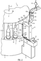
- FIG. 2 is a partial view of the container treatment machine 1 from the Fig. 1 shown in a perspective view. Essentially, the carousel 3 can be seen in the area of the curing device 6.
- the carousel 3 is arranged rotatable about the axis of rotation A in relation to a machine base 9.
- the container receptacles 4 are arranged at regular intervals on the carousel 3, in which the containers 2 are each clamped by means of the centering device 4a and the turntable 4b.
- the container receptacles 4 each comprise a shielding housing 7, which is in the form of a U-shaped plate about the axes of rotation of the container receptacles 4 are formed. Two edges 72 of the U-shaped shielding housing 7 each form an access opening 71.
- the curing device 6 is fixedly attached to the arm 10 of the machine base 9. Between the boom 10 and the curing device 6, the linear adjustment 68 is arranged, with which the curing device 6 can be adjusted along the double arrow radially to the axis of rotation A of the carousel 3. This sets the distance between the curing device 6 and the container 2.
- the linear adjustment 68 here comprises a servo motor, a spindle and guide rails (not shown here).
- the curing device 6 can be pivoted by means of the swivel joint 69 and can be folded away from the carousel 3 for maintenance purposes (more precisely in FIGS 3A and 3B shown).
- the locking element 66 which is designed as a quick-action lock, serves to lock the swivel joint 69. It can also be seen that the safety switch 67 is arranged in the region of the two legs connected by the swivel joint 69 and detects that the curing device 6 folds away. As a result, the curing device 6 is automatically deactivated during maintenance for the safety of the operating personnel.
- the curing device 6 comprises the shielding element 62, which interacts with the access opening 71 of the shielding housing 7.
- the shielding element 62 is formed like a shield and comprises the wings 62a and 62c, which are cylindrical in the conveying direction as far as possible along the outer circumference of the carousel 3, and the two edge elements 62b and 62d formed at the top and bottom. The two wings 62a and 62c protrude into the adjacent container receptacles 4 or their associated shielding housings 7.
- the shielding element 62 has a gap to the edges 72 of the shielding housing 7 in order to ensure that the carousel 3 can be easily rotated. Because the wings 62a and 62c are slightly curved, there is a direct light emission up to that in FIG Fig. 1 shown direct print heads 5 W -5 K not possible. Furthermore, the upper and lower edge elements 62b and 62d overlap the corresponding end faces of the shielding housings 7 or the carousel 3, so that no light radiation can escape upwards or downwards.
- the shielding element 62 is connected to the housing 61 of the curing device 6 via the collar 62e and can be adjusted using the adjustment devices 64a, 64b.
- the linear adjustment 68 is adjusted, the changed distance of the shielding element can be changed 62 can be adjusted to the shielding housings 7.
- the screws 64b are loosened, and the shielding element 62 can be displaced radially with respect to the carousel 3 through the elongated holes 64a formed in the collar 62e. The screws 64b are then tightened again.
- the air exchange openings 65 are formed in the collar 62e, each of which forms a labyrinth of rays through overlapping elements (not shown here).
- the air supplied with the shielding housings 7 can also escape through the air exchange openings 65 and a constant pressure is thus created in front of the curing device 6.
- the supply lines 81a for air and 81b for electrical current and also water cooling lines are indicated.
- the air is discharged from the curing device 6 via the hose 81a and filtered by means of the activated carbon system 80.
- the supply lines 81a and 81b can be easily separated using the quick-release fasteners 82a and 82b.
- the tare cable system 83 is also intended to hold the supply line 81a and 81b upwards.
- the supply lines 81a and 81b are correspondingly adjusted so that the operating personnel are not hindered during maintenance.
- the curing device 6 of the container treatment machine 1 can be seen in a working position A and in the Figure 3B in a maintenance position W.
- the curing device 6 is in a substantially vertical working position A, so that the shielding element 62 forms a chamber with the shielding housing 7. As described above, this prevents light from escaping from this area. It can also be seen that the carousel 3 rotates about the axis A. The distance between the curing device 6 and the container 2 can be adjusted via the linear adjustment 68.
- the Figure 3B First move the linear adjustment 68 outwards from the carousel 3 (to the right in the figure), so that the edge elements 62b, 62d of the shielding element 62 are released for folding away. Subsequently, the curing device 6 in the Figure 3B folded in a clockwise direction so that the light exit opening 63 points upward and the curing device 6 is in the maintenance position W. At the same time, the safety switch 67 is released by folding away, whereby the light source (not shown here) in the curing device 6 is deactivated. This prevents light radiation from continuing to escape during maintenance.
- the swivel joint 69 makes it particularly easy to fold the curing device 6 into the maintenance position W, in which the interior of the curing device 6 can be easily reached.
- the container treatment machine 1 shown for printing on containers 2 is used as follows: The containers 2 are placed in the container receptacles 4 by the inlet star 11. Furthermore, the containers 2 are transported sequentially to the direct print heads 5 W - 5 K by means of the carousel 3 and printed there with light-curing printing inks of different colors (white, cyan, yellow, magenta, black). The light-curing printing inks are then cured by means of the curing device 6 by means of UV light radiation.
- the container receptacles 4 are provided with the shielding housing 7, the shielding element 62 of the curing device 6 interacting with the access opening 71 in such a way that no light radiation reaches the direct print heads 5 W -5 K.
- the containers 2 are then carried on from the drain star 12 to further treatment stations.
Landscapes
- Engineering & Computer Science (AREA)
- Manufacturing & Machinery (AREA)
- Health & Medical Sciences (AREA)
- General Health & Medical Sciences (AREA)
- Toxicology (AREA)
- Ink Jet (AREA)
- Coating Apparatus (AREA)
- Supply, Installation And Extraction Of Printed Sheets Or Plates (AREA)
- Heating, Cooling, Or Curing Plastics Or The Like In General (AREA)
Description
- Die Erfindung betrifft eine Behälterbehandlungsmaschine zur Bedruckung von Behältern mit den Merkmalen des Oberbegriffs von Patentanspruch 1.
- Üblicherweise werden Behälter für Produkte, wie beispielsweise Getränke, Hygieneartikel und dergleichen zur Kennzeichnung des Produkts und/oder für eine hochwertige Produktpräsentation mit einer Bedruckung versehen. Die Bedruckung kann dabei sowohl direkt auf eine Behälteraußenfläche und/oder als Zusatzdruck auf einem Etikett aufgebracht sein und beispielsweise Schriftzeichen, Logos, Muster und Farbverläufe aufweisen. Zum Aufbringen der Bedruckung werden die Behälter üblicherweise mit einer Transporteinrichtung, beispielsweise mit einem Karussell gefördert und dabei von Direktdruckköpfen mit z.B. lichtaushärtenden Drucktinten bedruckt. Zum mehrfarbigen Druck können dabei mehrere Direktdruckköpfe mit Drucktinten unterschiedlicher Farben an der Behälterbehandlungsmaschine angeordnet sein.
- Die zunächst flüssige Drucktinte wird auf den Behältern mit einer am Karussell stationär angeordneten Aushärteeinrichtung beispielsweise mit UV-Licht bestrahlt und dadurch ausgehärtet. Die Behälterbehandlungsmaschine kann dabei mehrere Aushärteeinrichtungen umfassen, die die Drucktinte jeweils nach dem Bedrucken einer Farbe aushärten. Alternativ ist auch denkbar, dass die Aushärteeinrichtung in Transportrichtung nach allen Direktdruckköpfen angeordnet ist und so die Drucktinten aller Farben gleichzeitig ausgehärtet werden. Schließlich ist auch eine Kombination denkbar, bei der z.B. mit UV-LEDs nach jedem Druckkopf ein sogenanntes Pinning (Erstanhärtung) durchgeführt wird und am Ende dann die Härtung des gesamten Aufdrucks.
- Nachteilig dabei ist, dass direkte Lichtstrahlung oder Streulicht der Aushärteeinrichtung auf die Direktdruckköpfe gelangt und dort unbeabsichtigt die Drucktinte aushärtet. Dadurch können die Düsen eines Direktdruckkopfs verstopfen und/oder die Druckqualität des Direktdrucks kann beeinträchtigt werden.
- Die
DE 10 2009 013 477 A1 offenbart eine Druckvorrichtung zum Bedrucken von Flaschen oder Behältern. - Aufgabe der vorliegenden Erfindung ist es daher, eine Behälterbehandlungsmaschine zur Bedruckung von Behältern bereitzustellen, bei der ein Verstopfen von Düsen des Direktdruckkopfs und/oder eine Verminderung der Druckqualität durch unbeabsichtigt ausgehärtete Drucktinte vermieden wird. Weiterhin dient die Vorrichtung dazu, die Gesundheitsgefährdung des Bedieners durch UV-Strahlung durch Abschirmung zu minimieren und UV-empfindliche Bauteile im Inneren der Maschine zu schonen.
- Gelöst wird diese Aufgabe bei einer Behälterbehandlungsmaschine zur Bedruckung von Behältern nach dem Oberbegriff von Patentanspruch 1 mit den Merkmalen des kennzeichnenden Teils, gemäß dem die Aushärteeinrichtung an der Behälterbehandlungsmaschine feststehend angeordnet ist und die Behälteraufnahmen jeweils mit einer Abschirmeinhausung zum Abschirmen der Lichtstrahlung ausgebildet sind, die wenigstens eine Zugangsöffnung für die Aushärteeinrichtung aufweist und die Aushärteeinrichtung mit einem Abschirmelement ausgebildet ist, das mit der Zugangsöffnung von wenigstens einer Abschirmeinhausung derart zusammenwirkt, dass ein direkter Lichtaustritt verhindert wird.
- Dadurch, dass die Behälteraufnahmen jeweils mit einer Abschirmeinhausung mit einer Zugangsöffnung versehen sind, können die Behälter durch die Zugangsöffnung von der Aushärteeinrichtung ohne eine Störung der Lichtstrahlung bestrahlt werden. Da zudem die Behälteraufnahmen jeweils mit einer eigenen Abschirmeinhausung versehen sind, gelangt weder direkte Lichtstrahlung noch Streulicht aus dem Bereich einer Behälteraufnahme zu benachbarten Behälteraufnahmen oder den Direktdruckköpfen. Weiterhin wird durch die Abschirmeinhausung vermieden, dass die Lichtstrahlung von der Aushärteeinrichtung durch einen transparenten Behälter hindurch in den Innenbereich der Transporteinrichtung gelangt und von dort zu den Direktdruckköpfen gestreut wird.
- Darüber hinaus ist der Zugangsöffnung gegenüberliegend das Abschirmelement an der Aushärteeinrichtung ausgebildet, so dass die Zugangsöffnung bei der Vorbeifahrt an der Aushärteeinrichtung gegen einen Lichtaustritt verschlossen wird. Hierdurch wird verhindert, dass direktes Licht von der Aushärteeinrichtung oder Streulicht durch die Zugangsöffnung austritt und von dort zum Direktdruckkopf gelangt.
- Demnach befindet sich also der Behälter bei der Bestrahlung im Bereich der Aushärteeinrichtung in einer in diesem Bereich entstehenden, im Wesentlichen quasi geschlossenen Kammer, die durch die Abschirmeinhausung und durch das Abschirmelement dort gebildet wird. Dadurch wird zumindest weitgehend verhindert, dass Lichtstrahlung der Aushärteeinrichtung direkt oder über Streulichtpfade zu einem Direktdruckkopf gelangt und dort die Drucktinte unbeabsichtigt aushärtet bzw. die Düsen verstopft.
- Die Behälterbehandlungsmaschine zur Bedruckung von Behältern kann in einer Getränkeverarbeitungsanlage angeordnet sein. Die Behälterbehandlungsmaschine kann einer Abfüllanlage zum Abfüllen eines Produkts in die Behälter nachgeordnet sein. Die Behälterbehandlungsmaschine kann auch direkt einer Streckblasmaschine für PET-Flaschen nachgeordnet werden. Die Behälter können dazu vorgesehen sein, Getränke, Hygieneartikel, Pasten, chemische, biologische und/oder pharmazeutische Produkte aufzunehmen. Die Behälter können Kunststoffflaschen, Glasflaschen, Dosen und/oder Tuben sein. Bei Kunststoff-Behältern kann es sich im Speziellen um PET-, HD-PE- oder PP-Behälter bzw. -flaschen handeln.
- Die Transporteinrichtung kann mit den Behälteraufnahmen und wenigstens einem Direktdrucckopf dazu ausgebildet sein, einen Behälterstrom kontinuierlich oder auch taktweise zu bedrucken. Die Transporteinrichtung kann ein Karussell sein, an dessen Umfang die Behälteraufnahmen angeordnet sind. Die Behälteraufnahmen können jeweils einen optional mit einem Direktantrieb angetriebenen Drehteller und eine Zentriervorrichtung umfassen. Der Drehteller und die Zentriervorrichtung können dazu ausgebildet sein, den Behälter am Behälterboden bzw. -mündung einzuspannen. Dem Karussell kann ein Einlauf- und/oder ein Auslaufstern zugeordnet sein, um die Behälter den Behälteraufnahmen zu- und/oder abzuführen. Ein Antrieb in der Behälterbehandlungsmaschine kann dazu vorgesehen sein, das Karussell um eine senkrechte Karussellachse zu drehen. Unter "senkrecht" wird hier die Richtung verstanden, deren Vektor auf den Erdmittelpunkt gerichtet ist. Weiterhin kann das Karussell eine Karussellebene aufweisen, die senkrecht zur Karussellachse verläuft.
- Die Direktdruckköpfe können dazu ausgebildet sein, mit einem Tintenstrahldruckverfahren zu drucken. "Tintenstrahldruckverfahren" kann hier bedeuten, dass die Drucktinte mittels einer Vielzahl von Düsen auf die Behälter aufbringbar ist. Die Düsen können jeweils ein Thermo- oder Piezoelement umfassen. Weiterhin können die Düsen dazu ausgebildet sein, Drucktröpfchen in einer Druckrichtung auf die Behälter abzugeben. Der Direktdruckkopf kann auch mit jedem anderen Direktdruckverfahren zur computergesteuerten Abgabe von Drucktröpfchen auf die Behälter ausgebildet sein.
- Der wenigstens eine Direktdruckkopf kann stationär an der Behälterbehandlungsmaschine angeordnet sein. "Stationär" kann hier bedeuten, dass sich der Direktdruckkopf nicht mit der Transporteinrichtung umlaufend mitbewegt. "Lichtaushärtende Drucktinte" kann bedeuten, dass durch die Lichtstrahlung in der Drucktinte eine chemische Reaktion ausgelöst wird, durch die die flüssige Drucktinte in eine im Wesentlichen feste oder pastöse Phase umgewandelt wird. Durch die Lichtstrahlung kann die Drucktinte polymerisiert werden, wobei hierzu optional in der Drucktinte Radikale aus zugegebenen Photoinitiatoren gebildet werden.
- Die Aushärteeinrichtung kann eine Lichtquelle, optional eine UV-Lichtquelle, umfassen. Im Allgemeinen wird zur Aushärtung von lichtaushärtender Drucktinte UV-Lichtstrahlung in einem Wellenlängenbereich von 200-480 nm verwendet. Die Lichtquelle kann eine Quecksilberdampf-Mitteldruck-, -Hochdruck- oder -Höchstdrucklampe sein. Ebenso kann die Lichtquelle eine Gasentladungslampe, eine Lichtbogenlampe eine UV-Leuchtdiode oder eine Xenon UV-Blitzlampe sein.
- "Stationäre" Aushärteeinrichtung bedeutet hier, dass die Aushärteeinrichtung an der Behälterbehandlungsmaschine feststehend angeordnet ist. Anders ausgedrückt kann das bedeuten, dass sich die Aushärteeinrichtung nicht mit der Transporteinrichtung umlaufend mitbewegt. Die Aushärteeinrichtung kann an der Behälterbehandlungsmaschine derart angeordnet sein, dass im Betrieb die Behälter mittels der Transporteinrichtung an der stationären Aushärteeinrichtung zur Aushärtung der Drucktinte vorbeigeführt werden.
- Die Abschirmeinhausung kann rinnenartig zwischen dem Drehteller und der Zentriervorrichtung der Behälteraufnahmen angeordnet sein. Die beiden Enden der rinnenartig ausgebildeten Abschirmeinhausung können mit Abschlussblenden versehen sein. Die Abschirmeinhausung kann als gebogenes und/oder abgewinkeltes Blechelement ausgeführt sein. Ebenso kann die Abschirmeinhausung mehrere zusammengefügte Blechelemente umfassen. Die Abschirmeinhausung kann kammerartig um die Behälteraufnahmen ausgebildet sein. Die Zugangsöffnung kann zwischen den Längsrändern der rinnenförmigen Abschirmeinhausung ausgebildet sein. Bei einer als Karussell ausgebildeten Transporteinrichtung kann die Zugangsöffnung der Abschirmeinhausung radial nach außen ausgebildet sein. Dabei kann die stationäre Aushärteeinrichtung mit einer Lichtaustrittsöffnung radial nach innen auf die Karussellachse ausgerichtet sein, wobei optional die Lichtaustrittsöffnung mit wenigstens einer Zugangsöffnung der Abschirmeinhausungen im Betrieb korrespondiert.
- Das Abschirmelement der Aushärteeinrichtung kann wenigstens ein Blechelement umfassen, das mit der Abschirmeinhausung überlappt. Die Abschirmeinhausung und das Abschirmelement können derart ausgebildet sein, dass diese zum Aushärten der Drucktinte eine Kammer bilden. Dass ein direkter Lichtaustritt verhindert wird, kann bedeuten, dass die Abschirmeinhausung und das Abschirmelement derart zusammenwirken, dass ein Lichtstrahl ausgehend von der Aushärteeinrichtung und/oder von der Behälteroberfläche wenigstens einmal an dem Abschirmelement oder der Abschirmeinhausung reflektiert oder gestreut wird, bevor er aus der durch das Abschirmelement und der Abschirmeinhausung gebildeten Kammer austritt. Das Abschirmelement und/oder die Abschirmeinhausung können eine Oberflächenbeschichtung umfassen, die die Lichtstrahlung in einem Bereich von 0-30 %, optional in einem Bereich von 0-10 % reflektiert. Das Abschirmelement und/oder die Abschirmeinhausung können im Wesentlichen lichtabsorbierend ausgebildet sein. Das Abschirmelement und/oder die Abschirmeinhausung können zur besseren Absorption von flach auftreffender Lichtstrahlung mit einer strukturierten Oberfläche, optional mit Riffeln, ausgebildet sein.
- Die Abschirmeinhausung kann U-förmig entlang einer Längsachse der Behälteraufnahme ausgebildet sein und die Zugangsöffnung kann durch die freien Enden der U-Form im Wesentlichen parallel zur Förderrichtung der Transporteinrichtung gebildet sein. Durch die U-förmige Ausbildung der Abschirmeinhausung ist diese besonders einfach aus einem Blech herstellbar und damit besonders kostengünstig. "U-förmig" kann hier bedeuten, dass ein Querschnitt der Abschirmeinhausung im Wesentlichen ein U-Profil aufweist. "U-förmig" kann auch bedeuten, dass die Abschirmeinhausung aus einem im Wesentlichen einseitig geöffneten Rechteckprofil gebildet wird. Die U-Form kann bei einer als Karussell ausgebildeten Fördereinrichtung radial nach außen geöffnet sein. "Förderrichtung der Transporteinrichtung" kann bedeuten, dass dies die Richtung ist, in der sich die Behälteraufnahmen im Betrieb bewegen.
- Das Abschirmelement kann von den Rändern einer Lichtaustrittsöffnung der Aushärteeinrichtung über die Ränder der Zugangsöffnung hinaus schirmartig ausgebildet sein. Dadurch wird vermieden, dass Lichtstrahlung über die Ränder der Lichtaustrittsöffnung hinaus zu dem Drucckopf gelangt. Dass das Abschirmelement schirmartig ausgebildet ist, kann bedeuten, dass das Abschirmelement im Wesentlichen parallel zur Transportrichtung über Ränder der Lichtaustrittsöffnung hervorsteht. Das Abschirmelement sollte bevorzugt mindestens eine, am Besten 1,5 bis 2 Abschirmungsbreiten zu beiden Seiten der Aushärteinrichtung überstehen, um so optimal ein Strahlungslabyrinth auszubilden. Weiterhin kann das bedeuten, dass ein oberer und/oder ein unterer Rand des Abschirmelements mit entsprechenden Enden der Abschirmeinhausung überlappen.
- Das Abschirmelement und/oder ein Gehäuse der Aushärteeinrichtung können Luftaustauschöffnungen umfassen, die jeweils durch Überlappungselemente als Strahlenlabyrinth ausgebildet sind. Dadurch wird vermieden, dass sich durch die Fortbewegung der Transporteinrichtung und die sich ständig schließenden und öffnenden Aushärtekammern eine Luftpulsation ausbildet, die sonst eine Schwankung im Lichtspektrum der Aushärteeinrichtung zur Folge hätte. "Labyrinthartig" kann hier bedeuten, dass die Überlappungselemente zueinander einen Abstand aufweisen, jedoch derart versetzt angeordnet sind, dass kein direkter Lichtdurchtritt möglich ist.
- Der Abstand der Aushärteeinrichtung zu den Behälteraufnahmen kann mittels einer Linearverstellung einstellbar sein. Dadurch kann einerseits die Bestrahlungsstärke auf der Behälteroberfläche angepasst werden und andererseits die Aushärteeinrichtung auf verschiedene Behältertypen (beispielsweise mit unterschiedlichen Durchmessern). Die Linearverstellung kann dazu ausgebildet sein, die Aushärteeinrichtung senkrecht zur Förderrichtung der Transporteinrichtung zu verfahren. Die Linearverstellung kann eine Führungsschiene und/oder eine Spindel umfassen. "Abstand" kann hier bedeuten, dass dies der senkrechte Abstand der Aushärteeinrichtung auf die Förderrichtung der Transporteinrichtung ist.
- Die Linearverstellung kann mit einem Antrieb ausgebildet sein, der über eine Maschinensteuerung zur Verstellung des Abstands ansteuerbar ist. Dadurch kann die Linearverstellung per Steuerungsbefehl besonders präzise bzw. automatisch verstellt werden. Der Antrieb kann ein Direktantrieb, beispielsweise ein Servo- oder ein Schrittmotor sein. Der Servomotor kann einen Drehgeber zur Erfassung der Winkelposition der Motorachse umfassen. Dadurch kann über die Steigung der Spindel der Abstand der Linearverstellung zur Behälteroberfläche genau berechnet werden. Weiterhin kann die Linearverstellung einen Anschlag zur absoluten Referenzierung umfassen.
- Die Maschinensteuerung kann zum Abrufen von Einstellparametern der Linearverstellung mit einer Sortenverwaltung verbunden sein. Dadurch kann der Abstand der Aushärteeinrichtung automatisch auf den verwendeten Behältertyp angepasst werden. Die Sortenverwaltung kann eine Datenbank in der Maschinensteuerung oder in einer entfernten Computereinrichtung sein.
- Das Abschirmelement kann über einen optional mit Langlöchern ausgebildeten Justagemechanismus gegenüber einer Lichtquelle der Aushärteeinrichtung verstellbar ausgebildet sein. Dadurch kann nach einer Verstellung der Aushärteeinrichtung der Abstand zwischen dem Abschirmelement und der Abschirmeinhausung justiert werden. Folglich wird der Lichtaustritt zwischen dem Abschirmelement und der Abschirmeinhausung minimiert.
- Die Aushärteeinrichtung kann mittels eines Drehgelenks aus einer Arbeitsposition in eine Wartungsposition schwenkbar ausgebildet sein. Dadurch kann die Lichtquelle in der Aushärteeinrichtung besonders einfach zum Austausch erreicht werden. Die Drehachse des Drehgelenks kann im Wesentlichen parallel zur Förderrichtung der Transporteinrichtung ausgerichtet sein.
- Die Aushärteeinrichtung kann in der Arbeitsposition mittels eines Verschlusselements arretierbar sein. Dadurch ist gewährleistet, dass in der Arbeitsposition keine unbeabsichtigte Schwenkung der Aushärteeinrichtung möglich ist. Das Verschlusselement kann ein Spannverschluss sein. Weiterhin kann die Aushärteeinrichtung Positionselemente umfassen, so dass die Aushärteeinrichtung nach wiederholter Schwenkung immer in derselben Arbeitsposition arretierbar ist.
- Ein Sicherheitssensor oder -schalter an der Aushärteeinrichtung kann derart ausgebildet sein, dass die Aushärteeinrichtung in der Wartungsposition automatisch deaktivierbar ist. Dadurch ist gewährleistet, dass die Aushärteeinrichtung bei einer Wartung nicht unbeabsichtigt Lichtstrahlung abgibt, die möglicherweise gesundheitsschädlich ist. Hierdurch ist die Aushärteeinrichtung besonders sicher wartbar. Der Sicherheitssensor oder -schalter kann zwischen zwei Schenkeln ausgebildet sein, die zur Schwenkung mit dem Drehgelenk verbunden sind. Der Sicherheitssensor oder -schalter kann zur Deaktivierung der Lichtquelle in der Aushärteeinrichtung ausgebildet sein. Außerdem kann die Konstruktion so erfolgen, dass der Strahler nur dann in die Wartungsposition gekippt werden kann, wenn die Versorgungsleitungen getrennt sind. Dadurch wird eine Gefährdung des Bedieners noch weiter ausgeschlossen. Der Sensor kann des Weiteren so ausgebildet sein, dass er im laufenden Betrieb erfassen kann, ob der Strahler schräg steht, also nicht exakt senkrecht, und ob deshalb die Gefahr besteht, dass Streustrahlung austreten könnte.
- Die Aushärteeinrichtung kann ein Aktivkohlefiltersystem zur Filterung der Abluft umfassen. Hierdurch wird das von UV-Lichtquellen mit signifikantem UV-C-Anteil üblicherweise erzeugte Ozon aus der Abluft herausgefiltert. Dadurch wird eine Gesundheitsgefährdung des Bedienpersonals durch Ozon vermieden. Das Aktivkohlefiltersystem kann einen Aktivkohlefilter und/oder ein Gebläse umfassen. Weiterhin kann das Aktivkohlefiltersystem in einem Gehäuse der Aushärteeinrichtung oder außerhalb des Gehäuses der Aushärteeinrichtung angeordnet sein. Das Aktivkohlefiltersystem kann über einen Schlauch mit dem Gehäuse der Aushärteeinrichtung verbunden sein.
- Versorgungsleitungen wie Kühlwasserleitungen, Kühl- bzw. Abluftleitungen sowie pneumatische und elektrische Leitungen der Aushärteeinrichtung können mit Schnellverschlüssen lösbar sein. Dadurch kann die Aushärteeinrichtung bei einer Wartung oder bei einem Austausch besonders schnell von der Behälterbehandlungsmaschine gelöst werden. Die Schnellverschlüsse können elektrische Stecker oder Verbindungsflansche in Luft- oder Flüssigkeitsleitungen sein.
- Die Versorgungsleitungen können mit einem tarierbaren Seilzugsystem aufgehängt sein. Dadurch ist die Versorgung der Aushärteeinrichtung von oben möglich, wobei bei einer Schwenkung der Aushärteeinrichtung aus der Arbeitsposition in die Wartungsposition die Versorgungsleitungen durch das tarierbare Seilzugsystem nachgeführt werden. Dadurch wird vermieden, dass die Versorgungsleitungen bei der Wartung das Bedienpersonal behindern.
- Weitere Merkmale und Vorteile der Erfindung werden nachfolgend anhand der in den Figuren dargestellten Ausführungsbeispiele erläutert. Dabei zeigt:
- Fig. 1
- eine Darstellung einer Behälterbehandlungsmaschine zur Bedruckung von Behältern in einer Draufsicht;
- Fig. 2
- eine Teildarstellung der Behälterbehandlungsmaschine aus der
Fig. 1 in einer perspektivischen Ansicht; - Fig. 3A
- eine seitliche Darstellung der Aushärteeinrichtung der Behälterbehandlungsmaschine der
Fig. 1 in einer Arbeitsposition; und - Fig. 3B
- eine seitliche Darstellung der Aushärteeinrichtung der Behälterbehandlungsmaschine der
Fig. 1 in einer Wartungsposition. -
Fig. 1 zeigt eine Darstellung der Behälterbehandlungsmaschine 1 zur Bedruckung der Behälter 2 in einer Draufsicht. Zu sehen ist, dass die Behälter 2 zunächst über den Einlaufstern 11 in den Behälteraufnahmen 4 der als Karussell ausgebildeten Transporteinrichtung 3 platziert werden. Die Behälteraufnahmen 4 sind dabei mittels eines Direktantriebs um die Behälterlängsachsen drehbar ausgebildet (hier nicht dargestellt). Mit dem Karussell 3 werden die Behälter 2 an den Direktdruckköpfen 5W, 5C, 5Y, 5M und 5K zur Bedruckung mit lichtaushärtenden Druckertinten vorbeigeführt. Nach der Bedruckung werden die Behälter 2 durch die Aushärteeinrichtung 6 mittels UV-Lichtstrahlung bestrahlt, wodurch die Drucktinte aushärtet. Anschließend werden die Behälter 2 durch den Auslaufstern 12 den Behälteraufnahmen 4 entnommen und weiteren Behandlungsstationen (beispielsweise einer Verpackungsstation) zugeführt. - Die Direktdruckköpfe 5 arbeiten hier mit dem Tintenstrahldruckverfahren. Dabei wird die lichtaushärtende Drucktinte aus einem Tintenvorrat entnommen und über eine Vielzahl von Druckdüsen direkt auf die Oberfläche der Behälter 2 aufgesprüht. Dadurch können die Behälter 2 mit einem individuellen Druckbild versehen werden. Mit jedem der Direktdruckköpfe 5W, 5C, 5Y, 5M und 5K werden die Behälter 2 sequenziell nacheinander mit den verschiedenen Farben Weiß, Cyan, Gelb, Magenta und Schwarz bedruckt, um ein vielfarbiges Druckbild zu generieren. Unmittelbar nach dem letzten Direktdruckkopf 5K sind die Drucktinten auf der Behälteroberfläche im Wesentlichen flüssig.
- Die Aushärteeinrichtung 6 umfasst hier ein Gehäuse 61, in dem eine nicht dargestellte UV-Lichtquelle angeordnet ist, die in einem Wellenlängenbereich von 200-480 nm UV-Licht durch die Lichtaustrittsöffnung 63 auf die Behälter 2 abstrahlt. Gleichzeitig dreht sich der Behälter 2 um die Drehachse B. Durch die Drehung wird die Drucktinte entlang des gesamten Behälterumfangs ausgehärtet. Auch eine Aushärtung ohne Drehung ist möglich, z.B. beim kontinuierlichen Aushärten von Formbehältern.
- Um die Direktdruckköpfe 5W-5K vor einer unbeabsichtigten Aushärtung der Drucktinte zu schützen, sind die Behälteraufnahmen 4 jeweils mit einer Abschirmeinhausung 7 ausgebildet, die eine Zugangsöffnung 71 für die Aushärteeinrichtung 6 aufweist. Die Abschirmeinhausung 7 ist hier U-förmig ausgebildet, d. h. sie hat im Querschnitt ein U-Profil. Die Enden des U-Profils benachbarter Abschirmeinhausungen 7 sind miteinander verbunden und im Wesentlichen am äußeren Umfang des Karussells 3 angeordnet. Hierdurch wird vermieden, dass die Lichtstrahlung der Aushärteeinrichtung 6 in den Innenbereich des Karussells 3 , in dem sich auch UVlichtempfindliche Bauteile befinden können, und von dort über Streulichtpfade zu den Direktdruckköpfen 5W-5K gelangt.
- Weiterhin umfasst die Aushärteeinrichtung 6 das Abschirmelement 62, das die Zugangsöffnung 71 der Abschirmeinhausung 7 über dessen Ränder hinweg abdeckt. Hierzu ist das Abschirmelement 62 schirmartig über die Ränder der Zugangsöffnung 71 hinaus ausgebildet. Dies ist daran zu erkennen, dass die Enden des Abschirmelements 62 weiter entlang der benachbarten Abschirmeinhausungen 7 ausgebildet sind. Das Abschirmelement 62 ist hier in Transportrichtung T um 100% länger ausgebildet, als die Zugangsöffnung 71 der Abschirmeinhausung 7.
- Während der Bedruckung und der Aushärtung der Drucktinte werden die Behälter 2 in den Behälteraufnahmen 4 kontinuierlich mit dem Karussell 3 transportiert. Denkbar ist auch, dass die Behälter 2 in einem Taktbetrieb transportiert und vor den Direktdruckköpfen 5W-5K bzw. vor der Aushärteeinrichtung 6 angehalten werden. Anders ausgedrückt, befinden sich beim Taktbetrieb die Behälter 2 direkt gegenüberliegend zu den einzelnen Direktdruckköpfen 5W-5K und werden lediglich um ihre Behälterlängsachsen B in den Behälteraufnahmen 4 gedreht.
- In der
Fig. 2 ist eine Teildarstellung der Behälterbehandlungsmaschine 1 aus derFig. 1 in einer perspektivischen Ansicht gezeigt. Zu sehen ist im Wesentlichen das Karussell 3 im Bereich der Aushärteeinrichtung 6. - Das Karussell 3 ist drehbar um die Drehachse A gegenüber einer Maschinenbasis 9 angeordnet. An dem Karussell 3 sind in regelmäßigen Abständen die Behälteraufnahmen 4 angeordnet, in denen die Behälter 2 jeweils mittels der Zentriervorrichtung 4a und dem Drehteller 4b eingespannt sind. Weiterhin ist zu sehen, dass die Behälteraufnahmen 4 jeweils eine Abschirmeinhausung 7 umfassen, die als U-förmiges Blech um die Drehachsen der Behälteraufnahmen 4 ausgebildet sind. Zwei Ränder 72 der U-förmigen Abschirmeinhausung 7 bilden dabei jeweils eine Zugangsöffnung 71.
- Weiterhin ist zu sehen, dass die Aushärteeinrichtung 6 an dem Ausleger 10 der Maschinenbasis 9 stationär befestigt ist. Zwischen dem Ausleger 10 und der Aushärteeinrichtung 6 ist die Linearverstellung 68 angeordnet, mit der die Aushärteeinrichtung 6 entlang des Doppelpfeils radial zur Drehachse A des Karussells 3 verstellt werden kann. Dadurch wird der Abstand zwischen der Aushärteeinrichtung 6 und dem Behälter 2 eingestellt. Die Linearverstellung 68 umfasst hier einen Servomotor, eine Spindel und Führungsschienen (hier nicht dargestellt). Darüber hinaus ist die Aushärteeinrichtung 6 mittels des Drehgelenks 69 schwenkbar und kann zur Wartung nach außen vom Karussell 3 weggeklappt werden (genauer in den
Fig. 3A und 3B dargestellt). Zur Arretierung des Drehgelenks 69 dient das Verschlusselement 66, das als Schnellspannverschluss ausgebildet ist. Weiterhin ist zu sehen, dass der Sicherheitsschalter 67 im Bereich der beiden durch das Drehgelenk 69 verbundenen Schenkel angeordnet ist und ein Wegklappen der Aushärteeinrichtung 6 detektiert. Hierdurch wird die Aushärteeinrichtung 6 bei der Wartung automatisch zur Sicherheit des Bedienpersonals deaktiviert. - Weiterhin ist zu sehen, dass die Aushärteeinrichtung 6 das Abschirmelement 62 umfasst, das mit der Zugangsöffnung 71 der Abschirmeinhausung 7 zusammenwirkt. Hierdurch wird beim Vorbeifahren der Behälteraufnahmen 4 an der Aushärteeinrichtung 6 jeweils eine im Wesentlichen geschlossene Kammer gebildet, durch die ein Lichtaustritt vermieden wird. Das Abschirmelement 62 ist schirmartig ausgebildet und umfasst die in Förderrichtung weitestgehend entlang des Außenumfangs des Karussells 3 zylindrisch ausgebildeten Flügel 62a und 62c, sowie die beiden oben und unten ausgebildeten Randelemente 62b und 62d. Die beiden Flügel 62a und 62c ragen dabei in die angrenzenden Behälteraufnahmen 4 bzw. deren zugeordneten Abschirmeinhausungen 7 hinein.
- Das Abschirmelement 62 weist zu den Rändern 72 der Abschirmeinhausung 7 einen Spalt auf, um eine leichte Drehbarkeit des Karussells 3 zu gewährleisten. Dadurch, dass die Flügel 62a und 62c leicht gebogen sind, ist ein direkter Lichtaustritt bis hin zu den in der
Fig. 1 dargestellten Direktdruckköpfen 5W-5K nicht möglich. Weiterhin überlappen die oberen und unteren Randelemente 62b und 62d die entsprechenden Endflächen der Abschirmeinhausungen 7 bzw. das Karussell 3, so dass keine Lichtstrahlung nach oben oder unten entweichen kann. - Darüber hinaus ist das Abschirmelement 62 über den Kragen 62e mit dem Gehäuse 61 der Aushärteeinrichtung 6 verbunden und kann mit der Justagevorrichtungen 64a, 64b verstellt werden. Bei einer Verstellung der Linearverstellung 68 kann so der veränderte Abstand des Abschirmelements 62 zu den Abschirmeinhausungen 7 justiert werden. Dabei werden die Schrauben 64b gelöst, und das Abschirmelement 62 kann durch die im Kragen 62e ausgebildete Langlöcher 64a radial in Bezug auf das Karussell 3 verschoben werden. Anschließend werden die Schrauben 64b wieder angezogen.
- Weiterhin ist zu sehen, dass im Kragen 62e die Luftaustauschöffnungen 65 ausgebildet sind, die jeweils durch hier nicht dargestellte Überlappungselemente ein Strahlenlabyrinth bilden. Dadurch kann bei einer Drehung des Karussells 3 die mit den Abschirmeinhausungen 7 zugeförderte Luft durch die Luftaustauschöffnungen 65 entweichen aber auch eintreten und es entsteht so ein gleichbleibender Druck vor der Aushärteeinrichtung 6.
- Des Weiteren sind die Versorgungsleitungen 81a für Luft und 81b für elektrischen Strom und auch Wasserkühlungsleitungen angedeutet. Über den Schlauch 81a wird die Luft aus der Aushärteeinrichtung 6 abgeführt und mittels des Aktivkohlesystems 80 gefiltert. Dieses umfasst einen Aktivkohlefilter und ein Radialgebläse (beides hier nicht dargestellt). Bei der Wartung können die Versorgungsleitungen 81a und 81b mittels der Schnellverschlüsse 82a und 82b einfach getrennt werden. Das tarierbare Seilzugsystem 83 ist weiterhin dazu vorgesehen, die Versorgungsleitung 81a und 81b nach oben zu haltern. Beim Wegklappen der Aushärteeinrichtung 6 werden so die Versorgungsleitungen 81a und 81b entsprechend nachgeführt, so dass das Bedienpersonal bei der Wartung nicht behindert wird.
- In den
Fig. 3A ist die Aushärteeinrichtung 6 der Behälterbehandlungsmaschine 1 in einer Arbeitsposition A zu sehen und in derFig. 3B in einer Wartungsposition W. - In der
Fig. 3A ist zu sehen, dass sich die Aushärteeinrichtung 6 in einer im Wesentlichen senkrechten Arbeitsposition A befindet, so dass das Abschirmelement 62 mit der Abschirmeinhausung 7 eine Kammer bildet. Dadurch wird, wie zuvor beschrieben, ein Lichtaustritt aus diesem Bereich verhindert. Weiterhin ist zu sehen, dass sich das Karussell 3 um die Achse A dreht. Über die Linearverstellung 68 kann dabei der Abstand der Aushärteeinrichtung 6 zum Behälter 2 justiert werden. - Bei der Wartung wird nun entsprechend der
Fig. 3B zunächst die Linearverstellung 68 vom Karussell 3 nach außen verfahren (in der Figur nach rechts), so dass die Randelemente 62b, 62d des Abschirmelements 62 zum Wegklappen freigegeben werden. Anschließend wird über das Drehgelenk 69 die Aushärteeinrichtung 6 in derFigur 3B im Uhrzeigersinn so geklappt, dass die Lichtaustrittsöffnung 63 nach oben zeigt und sich die Aushärteeinrichtung 6 in der Wartungsposition W befindet. Gleichzeitig wird durch das Wegklappen der Sicherheitsschalter 67 aufgelöst, wodurch die Lichtquelle (hier nicht dargestellt) in der Aushärteeinrichtung 6 deaktiviert wird. Hierdurch wird vermieden, dass bei der Wartung weiterhin Lichtstrahlung austritt. - Durch das Drehgelenk 69 ist es besonders einfach, die Aushärteeinrichtung 6 in die Wartungsposition W zu klappen, in der das Innenleben der Aushärteeinrichtung 6 gut erreichbar ist.
- Insgesamt wird also die in den
Fig. 1-3B dargestellte Behälterbehandlungsmaschine 1 zur Bedruckung von Behältern 2 wie folgt eingesetzt: Die Behälter 2 werden in den Behälteraufnahmen 4 durch den Einlaufstern 11 platziert. Weiterhin werden die Behälter 2 mittels des Karussells 3 sequenziell zu den Direktdruckköpfen 5W - 5K transportiert und dort mit lichtaushärtenden Drucktinten verschiedener Farben (Weiß, Cyan, Gelb, Magenta, Schwarz) bedruckt. Anschließend werden die lichtaushärtenden Drucktinten mittels der Aushärteeinrichtung 6 durch UV-Lichtstrahlung ausgehärtet. Damit keine Lichtstrahlung auf die Direktdruckköpfe 5W-5K gelangt, sind die Behälteraufnahmen 4 mit der Abschirmeinhausung 7 versehen, wobei das Abschirmelement 62 der Aushärteeinrichtung 6 mit der Zugangsöffnung 71 derart zusammenwirkt, dass keine Lichtstrahlung zu den Direktdruckköpfen 5W-5K gelangt. Anschließend werden die Behälter 2 vom Ablaufstern 12 zu weiteren Behandlungsstationen weitergeführt. - Mit der Behälterbehandlungsmaschine 1 in den
Fig. 1 - 3B ist es also möglich, ein Verstopfen der Düsen der Direktdruckköpfe 5W - 5K, eine Verminderung der Druckqualität durch unbeabsichtigt ausgehärtete Drucktinte zu vermeiden und die Gefährdung des Bedienpersonals durch UV-Strahlung zu minimieren Weiterhin werden UV-empfindliche Bauteile im Inneren der Maschine geschont. - Es versteht sich, dass im zuvor beschriebenen Ausführungsbeispiel genannte Merkmale nicht auf diese speziellen Kombinationen beschränkt sind.
Claims (14)
- Behälterbehandlungsmaschine (1) zur Bedruckung von Behältern (2) mit einer optional als Karussell ausgebildeten Transporteinrichtung (3) zum Transport der Behälter (2) in Behälteraufnahmen (4), mit wenigstens einem Direktdruckkopf (5W, 5C, 5Y, 5M, 5K,) zum Druck mit einer lichtaushärtenden Drucktinte und mit einer Aushärteeinrichtung (6) zum Aushärten der Drucktinte auf den Behältern (2) mittels Lichtstrahlung, optional UV-Lichtstrahlung,
dadurch gekennzeichnet, dass
die Aushärteeinrichtung (6) an der Behälterbehandlungsmaschine (1) feststehend angeordnet ist,
dass die Behälteraufnahmen (4) jeweils mit einer Abschirmeinhausung (7) zum Abschirmen der Lichtstrahlung ausgebildet sind, die wenigstens eine Zugangsöffnung (71) für die Aushärteeinrichtung (6) aufweist, und
dass die Aushärteeinrichtung (6) mit einem Abschirmelement (62) ausgebildet ist, das mit der Zugangsöffnung (71) von wenigstens einer Abschirmeinhausung (7) derart zusammenwirkt, dass ein direkter Lichtaustritt verhindert wird. - Behälterbehandlungsmaschine (1) nach Anspruch 1, wobei die Abschirmeinhausung (7) U-förmig entlang einer Längsachse (B) der Behälteraufnahme (4) ausgebildet ist und die Zugangsöffnung (71) durch die freien Enden (72) der U-Form im Wesentlichen parallel zur Förderrichtung (T) der Transporteinrichtung (3) gebildet wird.
- Behälterbehandlungsmaschine (1) nach Anspruch 1 oder 2, wobei das Abschirmelement (62) von den Rändern einer Lichtaustrittsöffnung (63) der Aushärteeinrichtung (6) über die Ränder der Zugangsöffnung (71) hinaus schirmartig ausgebildet ist.
- Behälterbehandlungsmaschine (1) nach wenigstens einem der Ansprüche 1 - 3, wobei das Abschirmelement (62) und/oder ein Gehäuse (61) der Aushärteeinrichtung (6) Luftaustauschöffnungen (65) umfasst, die jeweils durch Überlappungselemente als Strahlenlabyrinth ausgebildet sind.
- Behälterbehandlungsmaschine (1) nach wenigstens einem der Ansprüche 1 - 4, wobei der Abstand der Aushärteeinrichtung (6) zu den Behälteraufnahmen (4) mittels einer Linearverstellung (68) einstellbar ist.
- Behälterbehandlungsmaschine (1) nach Anspruch 5, wobei die Linearverstellung (68) mit einem Antrieb ausgebildet ist, der über eine Maschinensteuerung zur Verstellung des Abstands ansteuerbar ist.
- Behälterbehandlungsmaschine (1) nach Anspruch 6, wobei die Maschinensteuerung zum Abrufen von Einstellparametern der Linearverstellung mit einer Sortenverwaltung verbunden ist.
- Behälterbehandlungsmaschine (1) nach wenigstens einem der Ansprüche 1 - 7, wobei das Abschirmelement (62) über einen optional mit Langlöchern ausgebildeten Justagemechanismus (64a, 64b) gegenüber einer Lichtquelle der Aushärteeinrichtung (6) verstellbar ausgebildet ist.
- Behälterbehandlungsmaschine (1) nach wenigstens einem der Ansprüche 1 - 8, wobei die Aushärteeinrichtung (6) mittels eines Drehgelenks (69) aus einer Arbeitsposition (A) in eine Wartungsposition (W) schwenkbar ausgebildet ist.
- Behälterbehandlungsmaschine (1) nach Anspruch 9, wobei die Aushärteeinrichtung (6) in der Arbeitsposition (A) mittels eines Verschlusselementes (66) arretierbar ist.
- Behälterbehandlungsmaschine (1) nach Anspruch 9 oder 10, wobei ein Sicherheitssensor oder -schalter (67) an der Aushärteeinrichtung (6) derart ausgebildet ist, dass die Aushärteeinrichtung in der Wartungsposition (W) automatisch deaktivierbar ist.
- Behälterbehandlungsmaschine (1) nach wenigstens einem der Ansprüche 1 - 11, wobei die Aushärteeinrichtung (6) ein Aktivkohlefiltersystem (80) zur Filterung der Abluft umfasst.
- Behälterbehandlungsmaschine (1) nach wenigstens einem der Ansprüche 1 - 12, wobei Versorgungsleitungen (81a, 81b) der Aushärteeinrichtung (6) mit Schnellverschlüssen (82a, 82b) lösbar sind.
- Behälterbehandlungsmaschine (1) nach Anspruch 13, wobei die Versorgungsleitungen (81a, 81b) mit einem tarierbaren Seilzugsystem (83) aufgehängt sind.
Applications Claiming Priority (1)
| Application Number | Priority Date | Filing Date | Title |
|---|---|---|---|
| DE102013217659.7A DE102013217659A1 (de) | 2013-09-04 | 2013-09-04 | Behälterbehandlungsmaschine zur Bedruckung von Behältern |
Publications (2)
| Publication Number | Publication Date |
|---|---|
| EP2848417A1 EP2848417A1 (de) | 2015-03-18 |
| EP2848417B1 true EP2848417B1 (de) | 2020-07-15 |
Family
ID=51225337
Family Applications (1)
| Application Number | Title | Priority Date | Filing Date |
|---|---|---|---|
| EP14178479.3A Active EP2848417B1 (de) | 2013-09-04 | 2014-07-25 | Behälterbehandlungsmaschine zur Bedruckung von Behältern |
Country Status (4)
| Country | Link |
|---|---|
| US (1) | US9302463B2 (de) |
| EP (1) | EP2848417B1 (de) |
| CN (1) | CN104417055B (de) |
| DE (1) | DE102013217659A1 (de) |
Families Citing this family (36)
| Publication number | Priority date | Publication date | Assignee | Title |
|---|---|---|---|---|
| JP6364796B2 (ja) * | 2014-02-06 | 2018-08-01 | カシオ計算機株式会社 | 描画装置及び描画装置の描画方法 |
| DE102014116405B4 (de) * | 2014-11-10 | 2018-10-25 | Khs Gmbh | Druckvorrichtung sowie Verfahren zur Bedruckung von Behältern |
| CN112571985B (zh) * | 2015-03-04 | 2022-03-08 | 斯多里机械有限责任公司 | 数字印刷机和方法 |
| CN106274070B (zh) * | 2015-05-29 | 2018-02-02 | 大族激光科技产业集团股份有限公司 | 一种利用激光技术对玻璃奶瓶标记的装置及方法 |
| DE102015222996A1 (de) * | 2015-11-20 | 2017-05-24 | Krones Ag | Aushärtestation und Verfahren zum Aushärten von Druckfarbe eines Direktdrucks auf Behältern |
| DE102015222999A1 (de) * | 2015-11-20 | 2017-05-24 | Krones Ag | Direktdruckmaschine und Verfahren zur Bedruckung von Behältern mit einem Direktdruck |
| DE102016203722A1 (de) * | 2016-03-08 | 2017-09-14 | Krones Ag | Vorrichtung zum Bedrucken von Verschlüssen verschlossener Behälter |
| RU2018141754A (ru) | 2016-05-12 | 2020-06-15 | Анхойзер-Буш Инбев С.А. | Стеклотара, имеющая изображение, выполненное посредством струйной печати, и способ ее изготовления |
| CN109963717B (zh) * | 2016-11-02 | 2021-03-09 | 唐杰有限公司 | 固持装置 |
| CN106585096A (zh) * | 2016-11-05 | 2017-04-26 | 童舟 | 喷印系统 |
| US10913995B2 (en) | 2017-07-14 | 2021-02-09 | Stolle Machinery Company, Llc | Pretreatment assembly and method for treating work pieces |
| US10259249B2 (en) | 2017-07-14 | 2019-04-16 | Stolle Machinery Company, Llc | Post-treatment assembly and method for treating work pieces |
| DE102017215459A1 (de) | 2017-09-04 | 2019-03-07 | Krones Ag | Druckmaschine zum Direktbedrucken von Behältern |
| DE202017105318U1 (de) * | 2017-09-04 | 2018-12-06 | Krones Ag | Behandlungsmaschine für Behälter |
| DE102017215446A1 (de) * | 2017-09-04 | 2019-03-07 | Krones Ag | Druckmaschine zum Direktbedrucken von Behältern |
| CA3075092C (en) | 2017-09-19 | 2022-08-23 | Ball Corporation | Container decoration apparatus and method |
| CN107672298B (zh) * | 2017-10-25 | 2023-05-26 | 万兴(佛冈)玩具有限公司 | 一种具有多面表情的玩具的头部的转印转盘 |
| CN107791667A (zh) * | 2017-10-31 | 2018-03-13 | 合肥海闻自动化设备有限公司 | 一种金属片印刷加工装置 |
| US11472579B2 (en) | 2018-12-04 | 2022-10-18 | Gpcp Ip Holdings Llc | Film securing apparatus and method |
| US11752779B2 (en) | 2017-12-12 | 2023-09-12 | Gpcp Ip Holdings Llc | Food service cup dispensers, systems, and methods |
| US20190180392A1 (en) | 2017-12-12 | 2019-06-13 | Gpcp Ip Holdings Llc | Personalized food service material printing systems |
| US12077337B2 (en) | 2018-12-04 | 2024-09-03 | Yum Connect, LLC | Systems and methods for sealing a container |
| US20210309022A1 (en) * | 2020-04-03 | 2021-10-07 | Norwalt Design, Inc. | Printing apparatus for printing directly onto containers |
| US12337607B2 (en) | 2020-04-03 | 2025-06-24 | Norwalt Design, Inc. | Printing apparatus for printing directly onto containers |
| DE102020120290A1 (de) * | 2020-07-31 | 2022-02-03 | Krones Aktiengesellschaft | Vorrichtung zum Bedrucken oder Etikettieren von Behältern |
| DE102020120295A1 (de) | 2020-07-31 | 2022-02-03 | Krones Aktiengesellschaft | Vorrichtung zum Ausstatten von Behältern |
| US11787203B2 (en) | 2020-09-10 | 2023-10-17 | Ink Cups Now Llc. | System and method for hollow vessel printing |
| JP7658733B2 (ja) * | 2020-10-05 | 2025-04-08 | アルテミラ株式会社 | 印刷装置 |
| JP7470612B2 (ja) * | 2020-10-12 | 2024-04-18 | アルテミラ株式会社 | 印刷装置 |
| CN113183636B (zh) * | 2021-04-06 | 2024-12-06 | 江阴市华方新技术科研有限公司 | 一种多工位宝塔管转盘打标机构 |
| US11396191B1 (en) * | 2021-04-29 | 2022-07-26 | LSINC Corporation | Compact media decorator optimized for transparent and semi-transparent media |
| TWI778906B (zh) * | 2022-01-04 | 2022-09-21 | 峻亦股份有限公司 | 杯容器噴印機 |
| JP7833325B2 (ja) * | 2022-03-31 | 2026-03-19 | 三菱重工機械システム株式会社 | 印刷装置 |
| DE102022123030A1 (de) | 2022-09-09 | 2024-03-14 | Krones Aktiengesellschaft | Verfahren zur Erzeugung eines Metallglanzeffekts auf Behältern |
| DE102022122911A1 (de) * | 2022-09-09 | 2024-03-14 | Krones Aktiengesellschaft | Direktdruckmaschine |
| DE102023112590A1 (de) * | 2023-05-12 | 2024-11-14 | Homag Gmbh | Vorrichtung und Verfahren zum Bemustern eines Werkstücks |
Family Cites Families (18)
| Publication number | Priority date | Publication date | Assignee | Title |
|---|---|---|---|---|
| DE19516053C2 (de) * | 1995-05-04 | 2000-08-24 | Ist Metz Gmbh | UV-Strahler |
| BR9707189A (pt) * | 1996-01-26 | 1999-04-06 | Tetra Laval Holdings & Finance | Método e aparelho para impressão de imagens em material de empacotamento |
| DE19916474A1 (de) * | 1999-04-13 | 2000-10-26 | Ist Metz Gmbh | Bestrahlungsgerät |
| US6684770B2 (en) * | 2001-06-29 | 2004-02-03 | Deco Patents, Inc. | Apparatus and method for direct rotary printing compositions onto cylindrical articles |
| JP4040902B2 (ja) * | 2002-05-08 | 2008-01-30 | グンゼ株式会社 | 透明飲料ボトルの検査方法及びその検査装置 |
| JP3864903B2 (ja) * | 2002-12-13 | 2007-01-10 | コニカミノルタホールディングス株式会社 | インクジェットプリンタ |
| US6920822B2 (en) * | 2003-09-03 | 2005-07-26 | Stolle Machinery Company, Llc | Digital can decorating apparatus |
| WO2005025873A2 (en) * | 2003-09-17 | 2005-03-24 | Jemtex Ink Jet Printing Ltd. | Method and apparatus for printing selected information on bottles |
| DE102006001204C5 (de) * | 2006-01-10 | 2015-06-18 | Khs Gmbh | Verfahren zum Etikettieren von Flaschen oder dergleichen Behältern sowie Etikettiermaschine zum Durchführen des Verfahrens |
| WO2009018893A1 (de) * | 2007-08-03 | 2009-02-12 | Khs Ag | Vorrichtung und verfahren zum bedrucken von behältern |
| DE102009013477B4 (de) * | 2009-03-19 | 2012-01-12 | Khs Gmbh | Druckvorrichtung zum Bedrucken von Flaschen oder dergleichen Behältern |
| DE102009041527A1 (de) * | 2009-08-08 | 2011-02-10 | Till, Volker | Anlage zum Bedrucken von Behältern |
| WO2011102098A1 (ja) * | 2010-02-16 | 2011-08-25 | 株式会社ヤクルト本社 | 印字機構を具えた連続ロータリ式充填包装機械 |
| EP2595810B1 (de) * | 2010-07-23 | 2018-08-22 | Plastipak Packaging, Inc. | Drehsystem und verfahren zum bedrucken von behältern |
| DE102010034780A1 (de) * | 2010-08-18 | 2012-02-23 | Volker Till | Vorrichtung und Verfahren zum Bedrucken von Behältern |
| DE102011119171B3 (de) * | 2011-11-23 | 2013-02-21 | Khs Gmbh | Vorrichtung zur Behandlung von Behältern mit einer Absaugvorrichtung |
| JP2013215647A (ja) * | 2012-04-05 | 2013-10-24 | Gs Yuasa Corp | 紫外線照射装置 |
| DE102013205232A1 (de) * | 2013-03-25 | 2014-09-25 | Krones Ag | Druckvorrichtung zum Bedrucken von Behältern |
-
2013
- 2013-09-04 DE DE102013217659.7A patent/DE102013217659A1/de active Pending
-
2014
- 2014-07-25 EP EP14178479.3A patent/EP2848417B1/de active Active
- 2014-08-06 US US14/453,221 patent/US9302463B2/en active Active
- 2014-09-04 CN CN201410449126.7A patent/CN104417055B/zh active Active
Non-Patent Citations (1)
| Title |
|---|
| None * |
Also Published As
| Publication number | Publication date |
|---|---|
| DE102013217659A1 (de) | 2015-03-05 |
| EP2848417A1 (de) | 2015-03-18 |
| US9302463B2 (en) | 2016-04-05 |
| CN104417055B (zh) | 2016-08-24 |
| US20150059600A1 (en) | 2015-03-05 |
| CN104417055A (zh) | 2015-03-18 |
Similar Documents
| Publication | Publication Date | Title |
|---|---|---|
| EP2848417A1 (de) | Behälterbehandlungsmaschine zur Bedruckung von Behältern | |
| EP2845738B1 (de) | Vorrichtung zum Bedrucken von Behältern | |
| EP2762317B1 (de) | Vorrichtungen zum Bedrucken von Behältern und Verfahren dazu | |
| EP2439048B1 (de) | Verfahren zum Behandeln wenigstens eines Behälters in einer Behälterbehandlungsanlage | |
| EP3377325B1 (de) | Direktdruckmaschine und verfahren zur bedruckung von behältern mit einem direktdruck | |
| EP2799240A1 (de) | Rundläufermaschine zur Bedruckung von Behältern | |
| DE102016216627A1 (de) | Aushärtestation und Verfahren zum Aushärten von Druckfarbe eines Direktdrucks auf Behältern | |
| EP2250026B1 (de) | Druckvorrichtung zum bedrucken von flaschen oder dergleichen behältern | |
| EP2611695A1 (de) | Verfahren sowie vorrichtung zum behandeln von behältern | |
| DE102013214935A1 (de) | Druckstation und Verfahren für das Direktbedrucken von Behältern | |
| DE102009008138A1 (de) | Transportsystem für Flaschen oder dergleichen Behälter | |
| DE102013213843A1 (de) | Behälterbehandlungsvorrichtung zur Bedruckung von Behältern | |
| EP3450183B1 (de) | Direktdruckmaschine und -verfahren zur bedruckung von behältern mit einem direktdruck | |
| WO2013068379A1 (de) | Vorrichtung und verfahren zur behandlung und zuführung von behälterverschlüssen | |
| DE102014100392A1 (de) | Behälterbehandlungsmaschine zur Bedruckung von Behältern | |
| WO2015058889A1 (de) | Vorrichtung und verfahren zur behandlung von packmitteln | |
| DE102018211337A1 (de) | Direktdruckmaschine und -verfahren zur Bedruckung von Behältern mit einem Direktdruck | |
| EP2669088B1 (de) | Verschlusseinrichtung für Druckköpfe | |
| DE102015215723A1 (de) | Druckaggregat | |
| DE202013105244U1 (de) | Direktdruckmaschine zum Bedrucken von Behältern | |
| DE102015215722A1 (de) | Druckaggregat | |
| DE202016103010U1 (de) | Vorrichtung zum Tintenstrahl-Direktbedrucken von Behältern | |
| WO2019042647A1 (de) | Behandlungsmaschine und -verfahren für behälter | |
| DE112012004655B4 (de) | Vorrichtung und Verfahren zur Behandlung und Zuführung von Behälterverschlüssen | |
| DE102016202551A1 (de) | Verfahren, Druckkopf und Maschine zum Bedrucken eines Behälters |
Legal Events
| Date | Code | Title | Description |
|---|---|---|---|
| PUAI | Public reference made under article 153(3) epc to a published international application that has entered the european phase |
Free format text: ORIGINAL CODE: 0009012 |
|
| 17P | Request for examination filed |
Effective date: 20140725 |
|
| AK | Designated contracting states |
Kind code of ref document: A1 Designated state(s): AL AT BE BG CH CY CZ DE DK EE ES FI FR GB GR HR HU IE IS IT LI LT LU LV MC MK MT NL NO PL PT RO RS SE SI SK SM TR |
|
| AX | Request for extension of the european patent |
Extension state: BA ME |
|
| R17P | Request for examination filed (corrected) |
Effective date: 20150911 |
|
| RBV | Designated contracting states (corrected) |
Designated state(s): AL AT BE BG CH CY CZ DE DK EE ES FI FR GB GR HR HU IE IS IT LI LT LU LV MC MK MT NL NO PL PT RO RS SE SI SK SM TR |
|
| STAA | Information on the status of an ep patent application or granted ep patent |
Free format text: STATUS: EXAMINATION IS IN PROGRESS |
|
| 17Q | First examination report despatched |
Effective date: 20181120 |
|
| GRAP | Despatch of communication of intention to grant a patent |
Free format text: ORIGINAL CODE: EPIDOSNIGR1 |
|
| STAA | Information on the status of an ep patent application or granted ep patent |
Free format text: STATUS: GRANT OF PATENT IS INTENDED |
|
| INTG | Intention to grant announced |
Effective date: 20200214 |
|
| GRAS | Grant fee paid |
Free format text: ORIGINAL CODE: EPIDOSNIGR3 |
|
| GRAA | (expected) grant |
Free format text: ORIGINAL CODE: 0009210 |
|
| STAA | Information on the status of an ep patent application or granted ep patent |
Free format text: STATUS: THE PATENT HAS BEEN GRANTED |
|
| AK | Designated contracting states |
Kind code of ref document: B1 Designated state(s): AL AT BE BG CH CY CZ DE DK EE ES FI FR GB GR HR HU IE IS IT LI LT LU LV MC MK MT NL NO PL PT RO RS SE SI SK SM TR |
|
| REG | Reference to a national code |
Ref country code: CH Ref legal event code: EP Ref country code: GB Ref legal event code: FG4D Free format text: NOT ENGLISH |
|
| REG | Reference to a national code |
Ref country code: DE Ref legal event code: R096 Ref document number: 502014014445 Country of ref document: DE |
|
| REG | Reference to a national code |
Ref country code: IE Ref legal event code: FG4D Free format text: LANGUAGE OF EP DOCUMENT: GERMAN |
|
| REG | Reference to a national code |
Ref country code: AT Ref legal event code: REF Ref document number: 1290587 Country of ref document: AT Kind code of ref document: T Effective date: 20200815 |
|
| REG | Reference to a national code |
Ref country code: LT Ref legal event code: MG4D |
|
| REG | Reference to a national code |
Ref country code: NL Ref legal event code: MP Effective date: 20200715 |
|
| PG25 | Lapsed in a contracting state [announced via postgrant information from national office to epo] |
Ref country code: FI Free format text: LAPSE BECAUSE OF FAILURE TO SUBMIT A TRANSLATION OF THE DESCRIPTION OR TO PAY THE FEE WITHIN THE PRESCRIBED TIME-LIMIT Effective date: 20200715 Ref country code: PT Free format text: LAPSE BECAUSE OF FAILURE TO SUBMIT A TRANSLATION OF THE DESCRIPTION OR TO PAY THE FEE WITHIN THE PRESCRIBED TIME-LIMIT Effective date: 20201116 Ref country code: HR Free format text: LAPSE BECAUSE OF FAILURE TO SUBMIT A TRANSLATION OF THE DESCRIPTION OR TO PAY THE FEE WITHIN THE PRESCRIBED TIME-LIMIT Effective date: 20200715 Ref country code: SE Free format text: LAPSE BECAUSE OF FAILURE TO SUBMIT A TRANSLATION OF THE DESCRIPTION OR TO PAY THE FEE WITHIN THE PRESCRIBED TIME-LIMIT Effective date: 20200715 Ref country code: BG Free format text: LAPSE BECAUSE OF FAILURE TO SUBMIT A TRANSLATION OF THE DESCRIPTION OR TO PAY THE FEE WITHIN THE PRESCRIBED TIME-LIMIT Effective date: 20201015 Ref country code: GR Free format text: LAPSE BECAUSE OF FAILURE TO SUBMIT A TRANSLATION OF THE DESCRIPTION OR TO PAY THE FEE WITHIN THE PRESCRIBED TIME-LIMIT Effective date: 20201016 Ref country code: LT Free format text: LAPSE BECAUSE OF FAILURE TO SUBMIT A TRANSLATION OF THE DESCRIPTION OR TO PAY THE FEE WITHIN THE PRESCRIBED TIME-LIMIT Effective date: 20200715 Ref country code: ES Free format text: LAPSE BECAUSE OF FAILURE TO SUBMIT A TRANSLATION OF THE DESCRIPTION OR TO PAY THE FEE WITHIN THE PRESCRIBED TIME-LIMIT Effective date: 20200715 Ref country code: NO Free format text: LAPSE BECAUSE OF FAILURE TO SUBMIT A TRANSLATION OF THE DESCRIPTION OR TO PAY THE FEE WITHIN THE PRESCRIBED TIME-LIMIT Effective date: 20201015 |
|
| PG25 | Lapsed in a contracting state [announced via postgrant information from national office to epo] |
Ref country code: LV Free format text: LAPSE BECAUSE OF FAILURE TO SUBMIT A TRANSLATION OF THE DESCRIPTION OR TO PAY THE FEE WITHIN THE PRESCRIBED TIME-LIMIT Effective date: 20200715 Ref country code: RS Free format text: LAPSE BECAUSE OF FAILURE TO SUBMIT A TRANSLATION OF THE DESCRIPTION OR TO PAY THE FEE WITHIN THE PRESCRIBED TIME-LIMIT Effective date: 20200715 Ref country code: PL Free format text: LAPSE BECAUSE OF FAILURE TO SUBMIT A TRANSLATION OF THE DESCRIPTION OR TO PAY THE FEE WITHIN THE PRESCRIBED TIME-LIMIT Effective date: 20200715 Ref country code: IS Free format text: LAPSE BECAUSE OF FAILURE TO SUBMIT A TRANSLATION OF THE DESCRIPTION OR TO PAY THE FEE WITHIN THE PRESCRIBED TIME-LIMIT Effective date: 20201115 |
|
| REG | Reference to a national code |
Ref country code: CH Ref legal event code: PL |
|
| PG25 | Lapsed in a contracting state [announced via postgrant information from national office to epo] |
Ref country code: NL Free format text: LAPSE BECAUSE OF FAILURE TO SUBMIT A TRANSLATION OF THE DESCRIPTION OR TO PAY THE FEE WITHIN THE PRESCRIBED TIME-LIMIT Effective date: 20200715 |
|
| REG | Reference to a national code |
Ref country code: DE Ref legal event code: R097 Ref document number: 502014014445 Country of ref document: DE |
|
| REG | Reference to a national code |
Ref country code: BE Ref legal event code: MM Effective date: 20200731 |
|
| PG25 | Lapsed in a contracting state [announced via postgrant information from national office to epo] |
Ref country code: MC Free format text: LAPSE BECAUSE OF FAILURE TO SUBMIT A TRANSLATION OF THE DESCRIPTION OR TO PAY THE FEE WITHIN THE PRESCRIBED TIME-LIMIT Effective date: 20200715 Ref country code: LU Free format text: LAPSE BECAUSE OF NON-PAYMENT OF DUE FEES Effective date: 20200725 Ref country code: SM Free format text: LAPSE BECAUSE OF FAILURE TO SUBMIT A TRANSLATION OF THE DESCRIPTION OR TO PAY THE FEE WITHIN THE PRESCRIBED TIME-LIMIT Effective date: 20200715 Ref country code: RO Free format text: LAPSE BECAUSE OF FAILURE TO SUBMIT A TRANSLATION OF THE DESCRIPTION OR TO PAY THE FEE WITHIN THE PRESCRIBED TIME-LIMIT Effective date: 20200715 Ref country code: LI Free format text: LAPSE BECAUSE OF NON-PAYMENT OF DUE FEES Effective date: 20200731 Ref country code: CZ Free format text: LAPSE BECAUSE OF FAILURE TO SUBMIT A TRANSLATION OF THE DESCRIPTION OR TO PAY THE FEE WITHIN THE PRESCRIBED TIME-LIMIT Effective date: 20200715 Ref country code: EE Free format text: LAPSE BECAUSE OF FAILURE TO SUBMIT A TRANSLATION OF THE DESCRIPTION OR TO PAY THE FEE WITHIN THE PRESCRIBED TIME-LIMIT Effective date: 20200715 Ref country code: CH Free format text: LAPSE BECAUSE OF NON-PAYMENT OF DUE FEES Effective date: 20200731 Ref country code: DK Free format text: LAPSE BECAUSE OF FAILURE TO SUBMIT A TRANSLATION OF THE DESCRIPTION OR TO PAY THE FEE WITHIN THE PRESCRIBED TIME-LIMIT Effective date: 20200715 |
|
| PLBE | No opposition filed within time limit |
Free format text: ORIGINAL CODE: 0009261 |
|
| STAA | Information on the status of an ep patent application or granted ep patent |
Free format text: STATUS: NO OPPOSITION FILED WITHIN TIME LIMIT |
|
| PG25 | Lapsed in a contracting state [announced via postgrant information from national office to epo] |
Ref country code: BE Free format text: LAPSE BECAUSE OF NON-PAYMENT OF DUE FEES Effective date: 20200731 Ref country code: AL Free format text: LAPSE BECAUSE OF FAILURE TO SUBMIT A TRANSLATION OF THE DESCRIPTION OR TO PAY THE FEE WITHIN THE PRESCRIBED TIME-LIMIT Effective date: 20200715 |
|
| 26N | No opposition filed |
Effective date: 20210416 |
|
| GBPC | Gb: european patent ceased through non-payment of renewal fee |
Effective date: 20201015 |
|
| PG25 | Lapsed in a contracting state [announced via postgrant information from national office to epo] |
Ref country code: SK Free format text: LAPSE BECAUSE OF FAILURE TO SUBMIT A TRANSLATION OF THE DESCRIPTION OR TO PAY THE FEE WITHIN THE PRESCRIBED TIME-LIMIT Effective date: 20200715 |
|
| PG25 | Lapsed in a contracting state [announced via postgrant information from national office to epo] |
Ref country code: IE Free format text: LAPSE BECAUSE OF NON-PAYMENT OF DUE FEES Effective date: 20200725 Ref country code: GB Free format text: LAPSE BECAUSE OF NON-PAYMENT OF DUE FEES Effective date: 20201015 Ref country code: SI Free format text: LAPSE BECAUSE OF FAILURE TO SUBMIT A TRANSLATION OF THE DESCRIPTION OR TO PAY THE FEE WITHIN THE PRESCRIBED TIME-LIMIT Effective date: 20200715 |
|
| REG | Reference to a national code |
Ref country code: AT Ref legal event code: MM01 Ref document number: 1290587 Country of ref document: AT Kind code of ref document: T Effective date: 20200725 |
|
| PG25 | Lapsed in a contracting state [announced via postgrant information from national office to epo] |
Ref country code: AT Free format text: LAPSE BECAUSE OF NON-PAYMENT OF DUE FEES Effective date: 20200725 |
|
| PG25 | Lapsed in a contracting state [announced via postgrant information from national office to epo] |
Ref country code: TR Free format text: LAPSE BECAUSE OF FAILURE TO SUBMIT A TRANSLATION OF THE DESCRIPTION OR TO PAY THE FEE WITHIN THE PRESCRIBED TIME-LIMIT Effective date: 20200715 Ref country code: MT Free format text: LAPSE BECAUSE OF FAILURE TO SUBMIT A TRANSLATION OF THE DESCRIPTION OR TO PAY THE FEE WITHIN THE PRESCRIBED TIME-LIMIT Effective date: 20200715 Ref country code: CY Free format text: LAPSE BECAUSE OF FAILURE TO SUBMIT A TRANSLATION OF THE DESCRIPTION OR TO PAY THE FEE WITHIN THE PRESCRIBED TIME-LIMIT Effective date: 20200715 |
|
| PG25 | Lapsed in a contracting state [announced via postgrant information from national office to epo] |
Ref country code: MK Free format text: LAPSE BECAUSE OF FAILURE TO SUBMIT A TRANSLATION OF THE DESCRIPTION OR TO PAY THE FEE WITHIN THE PRESCRIBED TIME-LIMIT Effective date: 20200715 |
|
| PGFP | Annual fee paid to national office [announced via postgrant information from national office to epo] |
Ref country code: FR Payment date: 20250610 Year of fee payment: 12 |
|
| PGFP | Annual fee paid to national office [announced via postgrant information from national office to epo] |
Ref country code: DE Payment date: 20250604 Year of fee payment: 12 |
|
| PGFP | Annual fee paid to national office [announced via postgrant information from national office to epo] |
Ref country code: IT Payment date: 20250623 Year of fee payment: 12 |