EP2842199B1 - Procédé de connexion de conducteurs d'une nappe souple de liaison équipotentielle, ainsi que outil de sertissage, connecteurs et harnais équipé de tels connecteurs - Google Patents
Procédé de connexion de conducteurs d'une nappe souple de liaison équipotentielle, ainsi que outil de sertissage, connecteurs et harnais équipé de tels connecteurs Download PDFInfo
- Publication number
- EP2842199B1 EP2842199B1 EP13728777.7A EP13728777A EP2842199B1 EP 2842199 B1 EP2842199 B1 EP 2842199B1 EP 13728777 A EP13728777 A EP 13728777A EP 2842199 B1 EP2842199 B1 EP 2842199B1
- Authority
- EP
- European Patent Office
- Prior art keywords
- conductors
- connector
- connectors
- crimping
- cells
- Prior art date
- Legal status (The legal status is an assumption and is not a legal conclusion. Google has not performed a legal analysis and makes no representation as to the accuracy of the status listed.)
- Active
Links
Images
Classifications
-
- H—ELECTRICITY
- H01—ELECTRIC ELEMENTS
- H01B—CABLES; CONDUCTORS; INSULATORS; SELECTION OF MATERIALS FOR THEIR CONDUCTIVE, INSULATING OR DIELECTRIC PROPERTIES
- H01B5/00—Non-insulated conductors or conductive bodies characterised by their form
-
- H—ELECTRICITY
- H01—ELECTRIC ELEMENTS
- H01B—CABLES; CONDUCTORS; INSULATORS; SELECTION OF MATERIALS FOR THEIR CONDUCTIVE, INSULATING OR DIELECTRIC PROPERTIES
- H01B7/00—Insulated conductors or cables characterised by their form
- H01B7/0045—Cable-harnesses
-
- H—ELECTRICITY
- H01—ELECTRIC ELEMENTS
- H01B—CABLES; CONDUCTORS; INSULATORS; SELECTION OF MATERIALS FOR THEIR CONDUCTIVE, INSULATING OR DIELECTRIC PROPERTIES
- H01B7/00—Insulated conductors or cables characterised by their form
- H01B7/04—Flexible cables, conductors, or cords, e.g. trailing cables
-
- H—ELECTRICITY
- H01—ELECTRIC ELEMENTS
- H01B—CABLES; CONDUCTORS; INSULATORS; SELECTION OF MATERIALS FOR THEIR CONDUCTIVE, INSULATING OR DIELECTRIC PROPERTIES
- H01B7/00—Insulated conductors or cables characterised by their form
- H01B7/06—Extensible conductors or cables, e.g. self-coiling cords
-
- H—ELECTRICITY
- H01—ELECTRIC ELEMENTS
- H01R—ELECTRICALLY-CONDUCTIVE CONNECTIONS; STRUCTURAL ASSOCIATIONS OF A PLURALITY OF MUTUALLY-INSULATED ELECTRICAL CONNECTING ELEMENTS; COUPLING DEVICES; CURRENT COLLECTORS
- H01R12/00—Structural associations of a plurality of mutually-insulated electrical connecting elements, specially adapted for printed circuits, e.g. printed circuit boards [PCB], flat or ribbon cables, or like generally planar structures, e.g. terminal strips, terminal blocks; Coupling devices specially adapted for printed circuits, flat or ribbon cables, or like generally planar structures; Terminals specially adapted for contact with, or insertion into, printed circuits, flat or ribbon cables, or like generally planar structures
- H01R12/50—Fixed connections
- H01R12/59—Fixed connections for flexible printed circuits, flat or ribbon cables or like structures
- H01R12/65—Fixed connections for flexible printed circuits, flat or ribbon cables or like structures characterised by the terminal
- H01R12/69—Fixed connections for flexible printed circuits, flat or ribbon cables or like structures characterised by the terminal deformable terminals, e.g. crimping terminals
-
- H—ELECTRICITY
- H01—ELECTRIC ELEMENTS
- H01R—ELECTRICALLY-CONDUCTIVE CONNECTIONS; STRUCTURAL ASSOCIATIONS OF A PLURALITY OF MUTUALLY-INSULATED ELECTRICAL CONNECTING ELEMENTS; COUPLING DEVICES; CURRENT COLLECTORS
- H01R4/00—Electrically-conductive connections between two or more conductive members in direct contact, i.e. touching one another; Means for effecting or maintaining such contact; Electrically-conductive connections having two or more spaced connecting locations for conductors and using contact members penetrating insulation
- H01R4/10—Electrically-conductive connections between two or more conductive members in direct contact, i.e. touching one another; Means for effecting or maintaining such contact; Electrically-conductive connections having two or more spaced connecting locations for conductors and using contact members penetrating insulation effected solely by twisting, wrapping, bending, crimping, or other permanent deformation
- H01R4/18—Electrically-conductive connections between two or more conductive members in direct contact, i.e. touching one another; Means for effecting or maintaining such contact; Electrically-conductive connections having two or more spaced connecting locations for conductors and using contact members penetrating insulation effected solely by twisting, wrapping, bending, crimping, or other permanent deformation by crimping
- H01R4/20—Electrically-conductive connections between two or more conductive members in direct contact, i.e. touching one another; Means for effecting or maintaining such contact; Electrically-conductive connections having two or more spaced connecting locations for conductors and using contact members penetrating insulation effected solely by twisting, wrapping, bending, crimping, or other permanent deformation by crimping using a crimping sleeve
- H01R4/203—Electrically-conductive connections between two or more conductive members in direct contact, i.e. touching one another; Means for effecting or maintaining such contact; Electrically-conductive connections having two or more spaced connecting locations for conductors and using contact members penetrating insulation effected solely by twisting, wrapping, bending, crimping, or other permanent deformation by crimping using a crimping sleeve having an uneven wire-receiving surface to improve the contact
- H01R4/206—Electrically-conductive connections between two or more conductive members in direct contact, i.e. touching one another; Means for effecting or maintaining such contact; Electrically-conductive connections having two or more spaced connecting locations for conductors and using contact members penetrating insulation effected solely by twisting, wrapping, bending, crimping, or other permanent deformation by crimping using a crimping sleeve having an uneven wire-receiving surface to improve the contact with transversal grooves or threads
-
- H—ELECTRICITY
- H01—ELECTRIC ELEMENTS
- H01R—ELECTRICALLY-CONDUCTIVE CONNECTIONS; STRUCTURAL ASSOCIATIONS OF A PLURALITY OF MUTUALLY-INSULATED ELECTRICAL CONNECTING ELEMENTS; COUPLING DEVICES; CURRENT COLLECTORS
- H01R4/00—Electrically-conductive connections between two or more conductive members in direct contact, i.e. touching one another; Means for effecting or maintaining such contact; Electrically-conductive connections having two or more spaced connecting locations for conductors and using contact members penetrating insulation
- H01R4/24—Connections using contact members penetrating or cutting insulation or cable strands
-
- H—ELECTRICITY
- H01—ELECTRIC ELEMENTS
- H01R—ELECTRICALLY-CONDUCTIVE CONNECTIONS; STRUCTURAL ASSOCIATIONS OF A PLURALITY OF MUTUALLY-INSULATED ELECTRICAL CONNECTING ELEMENTS; COUPLING DEVICES; CURRENT COLLECTORS
- H01R4/00—Electrically-conductive connections between two or more conductive members in direct contact, i.e. touching one another; Means for effecting or maintaining such contact; Electrically-conductive connections having two or more spaced connecting locations for conductors and using contact members penetrating insulation
- H01R4/58—Electrically-conductive connections between two or more conductive members in direct contact, i.e. touching one another; Means for effecting or maintaining such contact; Electrically-conductive connections having two or more spaced connecting locations for conductors and using contact members penetrating insulation characterised by the form or material of the contacting members
- H01R4/64—Connections between or with conductive parts having primarily a non-electric function, e.g. frame, casing, rail
-
- H—ELECTRICITY
- H01—ELECTRIC ELEMENTS
- H01R—ELECTRICALLY-CONDUCTIVE CONNECTIONS; STRUCTURAL ASSOCIATIONS OF A PLURALITY OF MUTUALLY-INSULATED ELECTRICAL CONNECTING ELEMENTS; COUPLING DEVICES; CURRENT COLLECTORS
- H01R43/00—Apparatus or processes specially adapted for manufacturing, assembling, maintaining, or repairing of line connectors or current collectors or for joining electric conductors
- H01R43/04—Apparatus or processes specially adapted for manufacturing, assembling, maintaining, or repairing of line connectors or current collectors or for joining electric conductors for forming connections by deformation, e.g. crimping tool
- H01R43/042—Hand tools for crimping
-
- H—ELECTRICITY
- H01—ELECTRIC ELEMENTS
- H01R—ELECTRICALLY-CONDUCTIVE CONNECTIONS; STRUCTURAL ASSOCIATIONS OF A PLURALITY OF MUTUALLY-INSULATED ELECTRICAL CONNECTING ELEMENTS; COUPLING DEVICES; CURRENT COLLECTORS
- H01R43/00—Apparatus or processes specially adapted for manufacturing, assembling, maintaining, or repairing of line connectors or current collectors or for joining electric conductors
- H01R43/04—Apparatus or processes specially adapted for manufacturing, assembling, maintaining, or repairing of line connectors or current collectors or for joining electric conductors for forming connections by deformation, e.g. crimping tool
- H01R43/048—Crimping apparatus or processes
- H01R43/0482—Crimping apparatus or processes combined with contact member manufacturing mechanism
-
- H—ELECTRICITY
- H01—ELECTRIC ELEMENTS
- H01R—ELECTRICALLY-CONDUCTIVE CONNECTIONS; STRUCTURAL ASSOCIATIONS OF A PLURALITY OF MUTUALLY-INSULATED ELECTRICAL CONNECTING ELEMENTS; COUPLING DEVICES; CURRENT COLLECTORS
- H01R43/00—Apparatus or processes specially adapted for manufacturing, assembling, maintaining, or repairing of line connectors or current collectors or for joining electric conductors
- H01R43/16—Apparatus or processes specially adapted for manufacturing, assembling, maintaining, or repairing of line connectors or current collectors or for joining electric conductors for manufacturing contact members, e.g. by punching and by bending
-
- H—ELECTRICITY
- H01—ELECTRIC ELEMENTS
- H01R—ELECTRICALLY-CONDUCTIVE CONNECTIONS; STRUCTURAL ASSOCIATIONS OF A PLURALITY OF MUTUALLY-INSULATED ELECTRICAL CONNECTING ELEMENTS; COUPLING DEVICES; CURRENT COLLECTORS
- H01R2101/00—One pole
-
- H—ELECTRICITY
- H01—ELECTRIC ELEMENTS
- H01R—ELECTRICALLY-CONDUCTIVE CONNECTIONS; STRUCTURAL ASSOCIATIONS OF A PLURALITY OF MUTUALLY-INSULATED ELECTRICAL CONNECTING ELEMENTS; COUPLING DEVICES; CURRENT COLLECTORS
- H01R31/00—Coupling parts supported only by co-operation with counterpart
- H01R31/08—Short-circuiting members for bridging contacts in a counterpart
- H01R31/085—Short circuiting bus-strips
-
- H—ELECTRICITY
- H01—ELECTRIC ELEMENTS
- H01R—ELECTRICALLY-CONDUCTIVE CONNECTIONS; STRUCTURAL ASSOCIATIONS OF A PLURALITY OF MUTUALLY-INSULATED ELECTRICAL CONNECTING ELEMENTS; COUPLING DEVICES; CURRENT COLLECTORS
- H01R4/00—Electrically-conductive connections between two or more conductive members in direct contact, i.e. touching one another; Means for effecting or maintaining such contact; Electrically-conductive connections having two or more spaced connecting locations for conductors and using contact members penetrating insulation
- H01R4/10—Electrically-conductive connections between two or more conductive members in direct contact, i.e. touching one another; Means for effecting or maintaining such contact; Electrically-conductive connections having two or more spaced connecting locations for conductors and using contact members penetrating insulation effected solely by twisting, wrapping, bending, crimping, or other permanent deformation
- H01R4/18—Electrically-conductive connections between two or more conductive members in direct contact, i.e. touching one another; Means for effecting or maintaining such contact; Electrically-conductive connections having two or more spaced connecting locations for conductors and using contact members penetrating insulation effected solely by twisting, wrapping, bending, crimping, or other permanent deformation by crimping
- H01R4/182—Electrically-conductive connections between two or more conductive members in direct contact, i.e. touching one another; Means for effecting or maintaining such contact; Electrically-conductive connections having two or more spaced connecting locations for conductors and using contact members penetrating insulation effected solely by twisting, wrapping, bending, crimping, or other permanent deformation by crimping for flat conductive elements, e.g. flat cables
-
- H—ELECTRICITY
- H01—ELECTRIC ELEMENTS
- H01R—ELECTRICALLY-CONDUCTIVE CONNECTIONS; STRUCTURAL ASSOCIATIONS OF A PLURALITY OF MUTUALLY-INSULATED ELECTRICAL CONNECTING ELEMENTS; COUPLING DEVICES; CURRENT COLLECTORS
- H01R4/00—Electrically-conductive connections between two or more conductive members in direct contact, i.e. touching one another; Means for effecting or maintaining such contact; Electrically-conductive connections having two or more spaced connecting locations for conductors and using contact members penetrating insulation
- H01R4/58—Electrically-conductive connections between two or more conductive members in direct contact, i.e. touching one another; Means for effecting or maintaining such contact; Electrically-conductive connections having two or more spaced connecting locations for conductors and using contact members penetrating insulation characterised by the form or material of the contacting members
- H01R4/62—Connections between conductors of different materials; Connections between or with aluminium or steel-core aluminium conductors
-
- H—ELECTRICITY
- H01—ELECTRIC ELEMENTS
- H01R—ELECTRICALLY-CONDUCTIVE CONNECTIONS; STRUCTURAL ASSOCIATIONS OF A PLURALITY OF MUTUALLY-INSULATED ELECTRICAL CONNECTING ELEMENTS; COUPLING DEVICES; CURRENT COLLECTORS
- H01R4/00—Electrically-conductive connections between two or more conductive members in direct contact, i.e. touching one another; Means for effecting or maintaining such contact; Electrically-conductive connections having two or more spaced connecting locations for conductors and using contact members penetrating insulation
- H01R4/58—Electrically-conductive connections between two or more conductive members in direct contact, i.e. touching one another; Means for effecting or maintaining such contact; Electrically-conductive connections having two or more spaced connecting locations for conductors and using contact members penetrating insulation characterised by the form or material of the contacting members
- H01R4/64—Connections between or with conductive parts having primarily a non-electric function, e.g. frame, casing, rail
- H01R4/646—Connections between or with conductive parts having primarily a non-electric function, e.g. frame, casing, rail for cables or flexible cylindrical bodies
-
- H—ELECTRICITY
- H01—ELECTRIC ELEMENTS
- H01R—ELECTRICALLY-CONDUCTIVE CONNECTIONS; STRUCTURAL ASSOCIATIONS OF A PLURALITY OF MUTUALLY-INSULATED ELECTRICAL CONNECTING ELEMENTS; COUPLING DEVICES; CURRENT COLLECTORS
- H01R43/00—Apparatus or processes specially adapted for manufacturing, assembling, maintaining, or repairing of line connectors or current collectors or for joining electric conductors
- H01R43/04—Apparatus or processes specially adapted for manufacturing, assembling, maintaining, or repairing of line connectors or current collectors or for joining electric conductors for forming connections by deformation, e.g. crimping tool
- H01R43/048—Crimping apparatus or processes
-
- Y—GENERAL TAGGING OF NEW TECHNOLOGICAL DEVELOPMENTS; GENERAL TAGGING OF CROSS-SECTIONAL TECHNOLOGIES SPANNING OVER SEVERAL SECTIONS OF THE IPC; TECHNICAL SUBJECTS COVERED BY FORMER USPC CROSS-REFERENCE ART COLLECTIONS [XRACs] AND DIGESTS
- Y10—TECHNICAL SUBJECTS COVERED BY FORMER USPC
- Y10T—TECHNICAL SUBJECTS COVERED BY FORMER US CLASSIFICATION
- Y10T29/00—Metal working
- Y10T29/49—Method of mechanical manufacture
- Y10T29/49002—Electrical device making
- Y10T29/49117—Conductor or circuit manufacturing
- Y10T29/49174—Assembling terminal to elongated conductor
- Y10T29/49181—Assembling terminal to elongated conductor by deforming
-
- Y—GENERAL TAGGING OF NEW TECHNOLOGICAL DEVELOPMENTS; GENERAL TAGGING OF CROSS-SECTIONAL TECHNOLOGIES SPANNING OVER SEVERAL SECTIONS OF THE IPC; TECHNICAL SUBJECTS COVERED BY FORMER USPC CROSS-REFERENCE ART COLLECTIONS [XRACs] AND DIGESTS
- Y10—TECHNICAL SUBJECTS COVERED BY FORMER USPC
- Y10T—TECHNICAL SUBJECTS COVERED BY FORMER US CLASSIFICATION
- Y10T29/00—Metal working
- Y10T29/49—Method of mechanical manufacture
- Y10T29/49002—Electrical device making
- Y10T29/49117—Conductor or circuit manufacturing
- Y10T29/49204—Contact or terminal manufacturing
- Y10T29/49208—Contact or terminal manufacturing by assembling plural parts
- Y10T29/49222—Contact or terminal manufacturing by assembling plural parts forming array of contacts or terminals
-
- Y—GENERAL TAGGING OF NEW TECHNOLOGICAL DEVELOPMENTS; GENERAL TAGGING OF CROSS-SECTIONAL TECHNOLOGIES SPANNING OVER SEVERAL SECTIONS OF THE IPC; TECHNICAL SUBJECTS COVERED BY FORMER USPC CROSS-REFERENCE ART COLLECTIONS [XRACs] AND DIGESTS
- Y10—TECHNICAL SUBJECTS COVERED BY FORMER USPC
- Y10T—TECHNICAL SUBJECTS COVERED BY FORMER US CLASSIFICATION
- Y10T29/00—Metal working
- Y10T29/53—Means to assemble or disassemble
- Y10T29/5313—Means to assemble electrical device
- Y10T29/532—Conductor
- Y10T29/53209—Terminal or connector
- Y10T29/53213—Assembled to wire-type conductor
- Y10T29/53217—Means to simultaneously assemble multiple, independent conductors to terminal
-
- Y—GENERAL TAGGING OF NEW TECHNOLOGICAL DEVELOPMENTS; GENERAL TAGGING OF CROSS-SECTIONAL TECHNOLOGIES SPANNING OVER SEVERAL SECTIONS OF THE IPC; TECHNICAL SUBJECTS COVERED BY FORMER USPC CROSS-REFERENCE ART COLLECTIONS [XRACs] AND DIGESTS
- Y10—TECHNICAL SUBJECTS COVERED BY FORMER USPC
- Y10T—TECHNICAL SUBJECTS COVERED BY FORMER US CLASSIFICATION
- Y10T29/00—Metal working
- Y10T29/53—Means to assemble or disassemble
- Y10T29/5313—Means to assemble electrical device
- Y10T29/532—Conductor
- Y10T29/53209—Terminal or connector
- Y10T29/53213—Assembled to wire-type conductor
- Y10T29/53235—Means to fasten by deformation
-
- Y—GENERAL TAGGING OF NEW TECHNOLOGICAL DEVELOPMENTS; GENERAL TAGGING OF CROSS-SECTIONAL TECHNOLOGIES SPANNING OVER SEVERAL SECTIONS OF THE IPC; TECHNICAL SUBJECTS COVERED BY FORMER USPC CROSS-REFERENCE ART COLLECTIONS [XRACs] AND DIGESTS
- Y10—TECHNICAL SUBJECTS COVERED BY FORMER USPC
- Y10T—TECHNICAL SUBJECTS COVERED BY FORMER US CLASSIFICATION
- Y10T29/00—Metal working
- Y10T29/53—Means to assemble or disassemble
- Y10T29/5313—Means to assemble electrical device
- Y10T29/532—Conductor
- Y10T29/53209—Terminal or connector
- Y10T29/53213—Assembled to wire-type conductor
- Y10T29/53239—Means to fasten by elastic joining
Definitions
- the invention relates to a method for connecting uninsulated electrical conductors of a flexible bonding bonding sheet for connecting metal parts, in particular electrical current return networks of new generation aircraft skin made of a composite material.
- the invention also relates to a crimping tool capable of implementing this method, terminal and intermediate connectors for such conductors, and a flexible ribbon bonding harness equipotential equipped with such connectors to connect such a sheet of conductors to said metal parts of current return.
- the composite material of this new generation of skin comprises a heterogeneous material based on carbon fibers.
- the electrical interconnection functions were performed by the aluminum skin of the older generation.
- the aircraft manufacturers used it in effect for the current feedback of the consumer equipment, the setting at the same potential of all the metal parts, the EMC (Electromagnetic Compatibility) protection of the electrical installation, and the flows of the lightning currents - indirect and induced - and electrostatic charges.
- the invention can also be applied in any architecture or building for the passage of electricity requiring the equipotential current setting, in particular, but not exclusively, to fuselages of aircraft composite skin passenger cabins.
- the document FR 2826518 describes a method according to the preamble of claim 1.
- Composite carbon materials are poor conductors of electricity and poorly support the heating caused by the Joule effect. Such a coating can not therefore be used to perform the above functions.
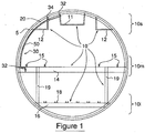
- this network consists of three longitudinal networks that run along the fuselage of the aircraft.
- the plane skin of carbon material 5 appears in the form of a curved wall on which are fixed three parts of an example of network 10 of the current return: upper longitudinal portions 10s, median 10m and lower 10i.
- the upper part 10s of the network comprises a central support 11 and lateral supports 12 metal.
- the central support 11 accommodates cabling and technical equipment, while the lateral supports 12 support the luggage compartments.
- the middle portion 10m consists of a metal cross member 14 on which are mounted the metal rails 15 of the passenger seats.
- the lower part 10i comprises another metal crosspiece 16 for supporting the metal cargo rails 18.
- Metal rods of structure 19 connect the middle metal crossmember 14 and the lower metal crossmember 16.
- the upper, middle and lower parts are interconnected by the transverse structure frame 20 made of composite material based on carbon fibers.
- a flexible harness 30 connects the supports 11 and 12 of the upper part 10s to the crosspiece 14.
- the harness 30 comprises two end connectors 32, fixed on the central support 11 and on the middle crosspiece 14, and an intermediate connector 34 fixed on a lateral support 12.
- the harness 30 consists of a flat sheet 50 of conductors non-electrically insulated, formed of strands of aluminum strands, in conjunction with the connectors 32 and 34.
- Such a harness allows a path in a narrow space, for example between the carbon frame 20 and a thermo-phonic protection panel or a cockpit panel of the passenger cabin.
- a network of electricity network is thus created in order to increase the operational safety.
- One of the critical points of this mesh lies in the manner of producing the intermediate connectors 34 and terminals 32 of connection between the sheet of aluminum conductors 50 and the metal structures constituting the network 10 of aircraft current return.
- Conductor connections are conventionally made from lugs and extensions for aluminum cables, or from a ground module.
- these lugs, extenders or modules do not allow to achieve reproducible, uniform, sealed and reliable connections with non-insulated aluminum stranded conductors, minimizing the mass with low cost.
- these aspects of mass, uniformity of effort distribution and cost are of fundamental importance.
- the existing solutions do not allow to distribute the forces and connection resistance of the conductors simultaneously, individually and homogeneously.
- the connector must be easily interfaced with the metal structures of the current return network.
- a uniform crimping of several conductors is not feasible by known crimping tools which generally combine a punch and a matrix, or several diametrically opposed punches, to crimp each conductor individually.
- the known connectors do not provide a reliable and durable seal for a multitude of non-electrically insulated aluminum alloy conductors, the seal being provided only by the insulating sheath of the cables with a connector pods or mass modules.
- the object of the invention is to provide a reproducible, uniform, tight and reliable connection for both intermediate and terminal connections of a conductor belt harness of the type described above.
- the invention provides for a simultaneous crimping of the conductors in connectors by the exercise of a continuous and uniform pressure in a crimping zone.
- the present invention relates to a crimp connection method of electrical conductors in equipotential bonding connectors to metal parts.
- These electrical conductors which form a flat and flexible sheet, are positioned in longitudinal and parallel individual cells, formed between two flat walls of each connector.
- These conductors are then crimped in a crimping zone by transverse and simultaneous punching of at least one connector wall. This transverse punching forms at least one corresponding transverse groove line on said at least one connector wall and, by charge transfer, on each of the conductors.
- the present invention also relates to a crimping tool comprising two shells, each shell having a main wall forming an inner face provided with at least one transverse rib, each shell also having end edges folded perpendicular to the walls so as to define an internal space.
- a conductor connector arranged perpendicular to the ribs may be introduced to implement the crimp connection method defined above.
- the crimping tool comprises two ribs on the inner face of a shell and a rib interposed between the two other ribs on the inner face of the other shell disposed facing during crimping.
- Another object of the invention is a modular multi-point connector for connecting a layer of conductors and parallel to a metal part of return of current.
- a connector comprises longitudinal internal housing cells of the conductors, these cells being formed by two inner faces of walls extending longitudinally. At least one crimping groove of the conductors extends transversely on at least one inner face of walls.
- This connector also comprises means for connection to metal parts of current return, these means being fixed by at least one opening formed in said walls.
- the invention also relates to a connecting harness capable of connecting metal parts of current return.
- This harness comprises parallel conductors forming a flat and flexible sheet, multipoint terminal and intermediate modular connectors defined above for connection to said metal parts, and an envelope covering the sheet and the connection between the sheet and the connectors.
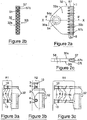
- Terminal connectors 32 such as that illustrated by the front views and in sections II-II and II'-II 'of Figures 2a to 2c , comprise an upper wall 32s and a lower wall 32i between which extend from one side 32c and along the entire length of this side, aligned individual cells 57.
- Each cell 57 is adapted to receive a conductor end for be crimped along its entire length.
- a chamfer 57c is provided at the entrance of each cell 57 to facilitate insertion of the conductor and maintain the cohesion of the aluminum strands of the conductors 51 ( figure 5 ) between them when inserting the conductors 51 into their individual cell. This avoids one or more Aluminum strands do not remain outside the crimp cell.
- the cells 57 are blind cavities.
- the end connectors 32 are connected to the metal support parts 11 and cross-member 14 ( figure 1 ) back current by appropriate fasteners and interfaces.
- the electrical contact area 54c surrounding the fixing opening 54 is extended so as not to exceed defined Joule heating limits.
- the terminal connector illustrated has a longitudinal axis of symmetry X'X with a tip advanced 32a, the opening 54 being made substantially in the center of this end.
- a fixing interface can receive a jogging, folding at a given angle, etc.
- the interface can be quick disconnect, by 1 ⁇ 4 turn or equivalent.
- connections are quick disassembly, so as to make a connection / disconnection for example in less than 10 seconds.
- the connections R1, R2, R3, then consist of two parts: a part 2 of the connector, not removable of the terminal connector 32, replaces the opening connection system 54.
- the geometry of the tip 32a ( figure 2a ) is modified locally to adapt this part 2 of the quick connect / disconnect system.
- the complementary part 3, mounted by screwing or clipping means 4 on the part 2, is then installed on a current return element 10 ( figure 1 ).
- a first section of this part 2 is constituted for example by a cable 2c ( figure 3c ) and can be mounted by crimping means 4c on the terminal connector 32
- This connector has upper 34s and lower walls 34i between which there are cavities 58 along the entire length of the sides 34c.
- the cells 58 are constituted by longitudinally through cavities which pierce the connector 34 from one side to the other. These cavities are terminated by chamfers 58c facilitating the access of the conductors to the cells 58.
- the conductors 51 are inserted individually into the cells 58 without interruption, which results in a gain in contact resistance and an increase in the reliability of the connection.
- the conductors are crimped into the cells in crimping zones Zs formed near one and / or the other of the sides 34c of the connector 34.
- the intermediate connector 34 may have a single advance 35 with an attachment opening 56 or, as shown, two symmetrical advances 35 with respect to the longitudinal axis X'X, with two attachment apertures 56.
- the extent of the The electrical contact pad 56a surrounding the fixing opening 56 is optimized according to the thermal clearance and the fastenings are made by screwing or equivalent through the openings 56.
- this interface can receive a jig, a folding at a given angle or equivalent. Also, other variants of this interface can be quick disconnect, 1 ⁇ 4 turn or equivalent.
- these intermediate connectors 34 make it possible to connect a current return cable of a device as close as possible to this equipment, forming a bypass tee, for example using the connections R1 to R3 illustrated by the Figures 3a to 3c .
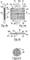
- each conductor 51 is composed of elementary aluminum strands 55 grouped in strand, as illustrated by the view in section of the figure 5 .
- the example conductor is a calibrated AWG12 gauge that has an outside diameter of about 2mm.
- the connector harness is thus adaptable depending on the configuration and dimensions of the installation to achieve.
- this connection can adapt to the resistivity of the connection to be connected, the transit current or overcurrent, the number of fixing points and the size of the installation as well as the number of parts to be connected.
- the geometry of the connectors makes it possible to reduce their total mass to the strict minimum.
- the thickness of the connectors 32 and 34 between their walls is just the maximum diameter of the conductors 51 while remaining sufficient to maintain robustness compatible with the presence of the cells.
- the connectors are advantageously constituted by an aluminum alloy for electrical use, and therefore have a low resistivity.
- a surface treatment of the connectors (nickel plating, tinning, etc.) is preferably carried out so that this surface is not very resistive and forms electrical connections interfaced with a tight fit by hooping with the supports 11, 12, and crosspieces 14. , 16 to be connected (cf. figure 1 ). Thus, the risks of galvanic corrosion at the electrical connection are eliminated.
- the sheet is also modular in order to facilitate its adaptability: the number of conductors 51, their section, the dimensions of the connectors, the number of intermediate connectors, the thickness and the width of the sheet are adjustable. In addition, the electrical and mechanical interfaces of connection are adaptable to the part to be connected.
- the finish at the end connectors 32 and intermediate 34 is provided by sections of thermo-shrinkable polyolefin sheath or equivalent.
- This outer envelope of finishing is, in another example, carried out by a local overmoulding, low or high pressure.
- a dedicated tool exerts a simultaneous and uniform pressure on the walls 32s and 32i of the end connectors 32 (or between the walls 34s and 34i of the intermediate connectors 34), in order to optimize the connection by minimizing the plastic deformation and the displacement of the material of the connectors.
- control of the crimping pressure does not cause crack in the connector 32.
- the crimping of all the cells 57 is performed simultaneously and in a single operation.
- the crimping compresses and deforms the individual strands of the conductors 51, but does not change the equivalent section of conductive material of the conductors.
- the elementary crimping length is such that the pulling force that must be exerted on a conductor 51 to slide or tear it from its crimping is greater than the elastic limit of this conductor.
- the drivers are not uncracked before crimping.
- the electrical resistance of an elemental crimp is then less than or equal to the electrical resistance of the length of conductor equivalent to the length of the crimping.
- the adequate surface treatment of the conductors 51 - by nickel plating, tin plating, silver plating or the like - allows electrochemical compatibility with that of the connectors. And the surface treatments are not destroyed by crimping.
- an example of crimping tool 21 comprises two shells, a so-called upper shell 21s and a so-called lower shell 21i.
- Each shell consists of a main wall P1 forming an internal face F1 and end edges B1 folded (at least on a shell) perpendicularly to the main wall P1 so as to define an internal space E1.
- the inner face F1 of the upper wall 21s is provided with a transverse rib N1.
- the connector 32 is inserted into the space E1 so that the shells 21s and 21i are disposed on either side of the walls 32s and 32i of the connector 32 to be crimped, a terminal connector in the example .
- the rib N1 of the shell 21s positioned transversely, is located approximately midway of the portion 51 p of the conductors 51 located in the cells 57. This positioning is also adapted to crimp the conductors in an intermediate connector according to the invention.
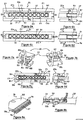
- each shell 21 s and 21 i of the tool 21 During crimping, the same pressure Ps is exerted on each shell 21 s and 21 i of the tool 21, so as to bring the two shells 21 s and 21 i until the contact edges B1, as illustrated by the Figures 6c and 6d .
- the rib N1 penetrates uniformly and simultaneously into the wall 32s of the connector 32, forms a transverse cylindrical groove Rc in this wall 32s and, by charge transfer, compresses and deforms the conductors 51.
- the upper shell 22s of the tool 22 has, as previously, a transverse rib N1.
- the inner face F2 of the lower shell 22i has two transverse ribs N2 and N3.
- the rib N1 is interposed between the ribs N2 and N3.
- the exercise of the pressures Ps on the shells 22s and 22i causes a uniform and simultaneous penetration of the ribs N1 to N3 in the walls 32s and 32i of the connector 32.
- grooves Rc are then formed on the walls 32s and 32i of the connector 32.
- the connector 32 is presented upside down on these Figures 8a and 8b compared to standard use.
- charge transfer from the grooves Rc the strands 55 of the conductors 51 are compressed and deformed alternately so as to have a waveform.
- the invention is not limited to the embodiments described and shown. It is for example possible to provide hybrid intermediate connectors formed in part by through cavities and by blind cells to house the conductors.
- the conductors are preferably aluminum alloy but could also be optionally copper or titanium alloy.
Landscapes
- Engineering & Computer Science (AREA)
- Manufacturing & Machinery (AREA)
- Connections Effected By Soldering, Adhesion, Or Permanent Deformation (AREA)
- Manufacturing Of Electrical Connectors (AREA)
- Connector Housings Or Holding Contact Members (AREA)
- Coupling Device And Connection With Printed Circuit (AREA)
Applications Claiming Priority (2)
| Application Number | Priority Date | Filing Date | Title |
|---|---|---|---|
| FR1253935A FR2990071B1 (fr) | 2012-04-27 | 2012-04-27 | Procede de connexion de conducteurs d'une nappe souple de liaison equipotentielle, ainsi que outil de sertissage, connecteurs et harnais equipe de tels connecteurs |
| PCT/FR2013/050865 WO2013160592A1 (fr) | 2012-04-27 | 2013-04-18 | Procédé de connexion de conducteurs d'une nappe souple de liaison équipotentielle, ainsi que outil de sertissage, connecteurs et harnais équipé de tels connecteurs |
Publications (2)
| Publication Number | Publication Date |
|---|---|
| EP2842199A1 EP2842199A1 (fr) | 2015-03-04 |
| EP2842199B1 true EP2842199B1 (fr) | 2016-06-22 |
Family
ID=46598724
Family Applications (1)
| Application Number | Title | Priority Date | Filing Date |
|---|---|---|---|
| EP13728777.7A Active EP2842199B1 (fr) | 2012-04-27 | 2013-04-18 | Procédé de connexion de conducteurs d'une nappe souple de liaison équipotentielle, ainsi que outil de sertissage, connecteurs et harnais équipé de tels connecteurs |
Country Status (9)
| Country | Link |
|---|---|
| US (1) | US9711925B2 (https=) |
| EP (1) | EP2842199B1 (https=) |
| JP (1) | JP6662636B2 (https=) |
| CN (1) | CN104488144B (https=) |
| BR (1) | BR112014026571B1 (https=) |
| CA (1) | CA2871224C (https=) |
| FR (1) | FR2990071B1 (https=) |
| RU (1) | RU2614152C2 (https=) |
| WO (1) | WO2013160592A1 (https=) |
Families Citing this family (1)
| Publication number | Priority date | Publication date | Assignee | Title |
|---|---|---|---|---|
| US11436011B2 (en) | 2020-02-18 | 2022-09-06 | Samsung Electronics Co., Ltd. | Processing method and processing device with matrix multiplication computation |
Family Cites Families (16)
| Publication number | Priority date | Publication date | Assignee | Title |
|---|---|---|---|---|
| SU1078520A1 (ru) * | 1982-09-23 | 1984-03-07 | Предприятие П/Я А-1698 | Устройство дл соединени токопровод щих жил опрессовкой |
| JPS60136480U (ja) * | 1984-02-23 | 1985-09-10 | ヒロセ電機株式会社 | 電気コネクタ |
| JPS62291879A (ja) * | 1986-06-12 | 1987-12-18 | 日立電線株式会社 | 平形ケ−ブルの接続工法 |
| JPH0815099B2 (ja) * | 1988-04-28 | 1996-02-14 | 日立電線株式会社 | 平形ケーブルの捻回接続法 |
| JPH0386585U (https=) * | 1989-12-21 | 1991-09-02 | ||
| JP3426742B2 (ja) * | 1994-10-07 | 2003-07-14 | 日本端子株式会社 | 圧着端子と電線の圧着構造及び圧着工具 |
| US5535512A (en) * | 1994-10-12 | 1996-07-16 | Armogan; Lloyd | Method of making a hermetically sealed electrical connector |
| JP3453630B2 (ja) * | 1999-06-30 | 2003-10-06 | 日本航空電子工業株式会社 | 同軸ケーブルコネクタ |
| FR2826518A1 (fr) * | 2001-06-20 | 2002-12-27 | Siemens Automotive Eeds System | Procede pour creer des equipotentialites sur un cable plat |
| JP2007188654A (ja) * | 2006-01-11 | 2007-07-26 | Yazaki Corp | 端子付きフラット回路体の製造方法及び製造装置 |
| JP4990011B2 (ja) * | 2007-04-13 | 2012-08-01 | 株式会社三英社製作所 | 電線接続方法及びそれに使用する電線接続用圧縮ダイス |
| RU2352036C1 (ru) * | 2007-06-25 | 2009-04-10 | Олег Алексеевич Чадов | Способ соединения проводников |
| JP5324769B2 (ja) * | 2007-10-19 | 2013-10-23 | 芝浦メカトロニクス株式会社 | 電子部品の実装装置及び実装方法 |
| JP2010146739A (ja) * | 2008-12-16 | 2010-07-01 | Sumitomo Wiring Syst Ltd | 電線接続スリーブ、電線接続スリーブの製造方法、電線接続スリーブが予め圧着されたリペア電線、および電線の接続方法 |
| JP2011003363A (ja) * | 2009-06-17 | 2011-01-06 | Hirose Electric Co Ltd | 圧着端子構造と端子圧着装置 |
| JP2011150822A (ja) * | 2010-01-20 | 2011-08-04 | Autonetworks Technologies Ltd | 圧着端子、圧着端子付き平形ケーブル、圧着端子付き平形ケーブルの製造に用いられる圧着装置 |
-
2012
- 2012-04-27 FR FR1253935A patent/FR2990071B1/fr not_active Expired - Fee Related
-
2013
- 2013-04-18 RU RU2014146152A patent/RU2614152C2/ru active
- 2013-04-18 US US14/396,592 patent/US9711925B2/en active Active
- 2013-04-18 JP JP2015507579A patent/JP6662636B2/ja not_active Expired - Fee Related
- 2013-04-18 CA CA2871224A patent/CA2871224C/fr not_active Expired - Fee Related
- 2013-04-18 EP EP13728777.7A patent/EP2842199B1/fr active Active
- 2013-04-18 WO PCT/FR2013/050865 patent/WO2013160592A1/fr not_active Ceased
- 2013-04-18 BR BR112014026571-2A patent/BR112014026571B1/pt not_active IP Right Cessation
- 2013-04-18 CN CN201380025934.4A patent/CN104488144B/zh active Active
Non-Patent Citations (1)
| Title |
|---|
| None * |
Also Published As
| Publication number | Publication date |
|---|---|
| JP2015518251A (ja) | 2015-06-25 |
| RU2014146152A (ru) | 2016-06-20 |
| EP2842199A1 (fr) | 2015-03-04 |
| WO2013160592A1 (fr) | 2013-10-31 |
| FR2990071B1 (fr) | 2014-05-02 |
| CN104488144B (zh) | 2017-11-17 |
| CA2871224A1 (fr) | 2013-10-31 |
| RU2614152C2 (ru) | 2017-03-23 |
| JP6662636B2 (ja) | 2020-03-11 |
| BR112014026571B1 (pt) | 2021-07-13 |
| CN104488144A (zh) | 2015-04-01 |
| US9711925B2 (en) | 2017-07-18 |
| FR2990071A1 (fr) | 2013-11-01 |
| US20150107893A1 (en) | 2015-04-23 |
| BR112014026571A2 (pt) | 2017-06-27 |
| CA2871224C (fr) | 2021-02-09 |
Similar Documents
| Publication | Publication Date | Title |
|---|---|---|
| EP2842208B1 (fr) | Harnais de liaison de retour courant, ainsi que procédé de montage sur un cadre de fuselage composite | |
| EP2063495B1 (fr) | Barre de connexion à interface plane | |
| EP2805392B1 (fr) | Procédé de raccordement, raccord de dérivation équipotentiel et réseau de retour courant à liaison équipotentielle dans une architecture non conductrice | |
| WO2015128305A1 (fr) | Cellule de stockage d'énergie électrique comportant au moins un élément mâle et un élément femelle, munis d'interfaces de connexion électrique | |
| CA2722398C (fr) | Chemin de cable evolutif pour aeronef a structure en materiau composite | |
| EP2842199B1 (fr) | Procédé de connexion de conducteurs d'une nappe souple de liaison équipotentielle, ainsi que outil de sertissage, connecteurs et harnais équipé de tels connecteurs | |
| CA2715406C (fr) | Chemin de cable pour aeronef a structure en materiau composite | |
| FR2584875A1 (fr) | Outil pour insertion de conducteur | |
| FR2545973A1 (fr) | Procede de realisation de cables electriques, les elements constitutifs conducteurs ou non, et les cables et ensembles correspondants, ainsi que les moyens de fabrication des elements conducteurs ou non | |
| EP3633794B1 (fr) | Connecteur | |
| EP2690710B1 (fr) | Procédé de fabrication d un dispositif de raccordement électrique des bornes appartenant a plusieurs appareils électriques modulaires, et dispositif de raccordement obtenu selon ce procédé | |
| EP3555963B1 (fr) | Element de connexion electrique muni d'un element de contact et son procédé de fabrication | |
| KR102547374B1 (ko) | 전력 케이블의 도체 접속구조 및 전력 케이블 도체 접속장치 | |
| EP3633690A1 (fr) | Cable electrique multi-conducteurs | |
| CN115398753A (zh) | 电导体和制造电导体的方法 | |
| EP3109948A1 (fr) | Procede de fabrication de contact electrique, et contact electrique | |
| FR2856526A1 (fr) | Dispositif de connexion pour panneau conducteur d'electricite | |
| FR3008832A1 (fr) | Barrette de coupure de puissance pour le raccordement de plusieurs lignes de cables electriques par pas | |
| FR2989526A1 (fr) | Dispositif de pontage utilisant des materiaux differents et procede de fabrication | |
| EP2463973A1 (fr) | Système de cheminement de câbles électrifié |
Legal Events
| Date | Code | Title | Description |
|---|---|---|---|
| PUAI | Public reference made under article 153(3) epc to a published international application that has entered the european phase |
Free format text: ORIGINAL CODE: 0009012 |
|
| 17P | Request for examination filed |
Effective date: 20141114 |
|
| AK | Designated contracting states |
Kind code of ref document: A1 Designated state(s): AL AT BE BG CH CY CZ DE DK EE ES FI FR GB GR HR HU IE IS IT LI LT LU LV MC MK MT NL NO PL PT RO RS SE SI SK SM TR |
|
| AX | Request for extension of the european patent |
Extension state: BA ME |
|
| RIN1 | Information on inventor provided before grant (corrected) |
Inventor name: BARRAUD, FLORIAN Inventor name: BIESSE, JEAN-LUC Inventor name: AYME, ARNAUD, CAMILLE Inventor name: BOUTOT, DAVID |
|
| DAX | Request for extension of the european patent (deleted) | ||
| GRAP | Despatch of communication of intention to grant a patent |
Free format text: ORIGINAL CODE: EPIDOSNIGR1 |
|
| INTG | Intention to grant announced |
Effective date: 20160315 |
|
| GRAS | Grant fee paid |
Free format text: ORIGINAL CODE: EPIDOSNIGR3 |
|
| GRAA | (expected) grant |
Free format text: ORIGINAL CODE: 0009210 |
|
| AK | Designated contracting states |
Kind code of ref document: B1 Designated state(s): AL AT BE BG CH CY CZ DE DK EE ES FI FR GB GR HR HU IE IS IT LI LT LU LV MC MK MT NL NO PL PT RO RS SE SI SK SM TR |
|
| REG | Reference to a national code |
Ref country code: GB Ref legal event code: FG4D Free format text: NOT ENGLISH |
|
| REG | Reference to a national code |
Ref country code: CH Ref legal event code: EP |
|
| REG | Reference to a national code |
Ref country code: IE Ref legal event code: FG4D Free format text: LANGUAGE OF EP DOCUMENT: FRENCH |
|
| REG | Reference to a national code |
Ref country code: AT Ref legal event code: REF Ref document number: 808153 Country of ref document: AT Kind code of ref document: T Effective date: 20160715 |
|
| REG | Reference to a national code |
Ref country code: DE Ref legal event code: R096 Ref document number: 602013008781 Country of ref document: DE |
|
| RAP2 | Party data changed (patent owner data changed or rights of a patent transferred) |
Owner name: SAFRAN ELECTRICAL & POWER Owner name: MECATRACTION |
|
| REG | Reference to a national code |
Ref country code: LT Ref legal event code: MG4D |
|
| REG | Reference to a national code |
Ref country code: NL Ref legal event code: MP Effective date: 20160622 |
|
| PG25 | Lapsed in a contracting state [announced via postgrant information from national office to epo] |
Ref country code: NO Free format text: LAPSE BECAUSE OF FAILURE TO SUBMIT A TRANSLATION OF THE DESCRIPTION OR TO PAY THE FEE WITHIN THE PRESCRIBED TIME-LIMIT Effective date: 20160922 Ref country code: FI Free format text: LAPSE BECAUSE OF FAILURE TO SUBMIT A TRANSLATION OF THE DESCRIPTION OR TO PAY THE FEE WITHIN THE PRESCRIBED TIME-LIMIT Effective date: 20160622 Ref country code: LT Free format text: LAPSE BECAUSE OF FAILURE TO SUBMIT A TRANSLATION OF THE DESCRIPTION OR TO PAY THE FEE WITHIN THE PRESCRIBED TIME-LIMIT Effective date: 20160622 |
|
| REG | Reference to a national code |
Ref country code: AT Ref legal event code: MK05 Ref document number: 808153 Country of ref document: AT Kind code of ref document: T Effective date: 20160622 |
|
| PG25 | Lapsed in a contracting state [announced via postgrant information from national office to epo] |
Ref country code: HR Free format text: LAPSE BECAUSE OF FAILURE TO SUBMIT A TRANSLATION OF THE DESCRIPTION OR TO PAY THE FEE WITHIN THE PRESCRIBED TIME-LIMIT Effective date: 20160622 Ref country code: SE Free format text: LAPSE BECAUSE OF FAILURE TO SUBMIT A TRANSLATION OF THE DESCRIPTION OR TO PAY THE FEE WITHIN THE PRESCRIBED TIME-LIMIT Effective date: 20160622 Ref country code: GR Free format text: LAPSE BECAUSE OF FAILURE TO SUBMIT A TRANSLATION OF THE DESCRIPTION OR TO PAY THE FEE WITHIN THE PRESCRIBED TIME-LIMIT Effective date: 20160923 Ref country code: RS Free format text: LAPSE BECAUSE OF FAILURE TO SUBMIT A TRANSLATION OF THE DESCRIPTION OR TO PAY THE FEE WITHIN THE PRESCRIBED TIME-LIMIT Effective date: 20160622 Ref country code: NL Free format text: LAPSE BECAUSE OF FAILURE TO SUBMIT A TRANSLATION OF THE DESCRIPTION OR TO PAY THE FEE WITHIN THE PRESCRIBED TIME-LIMIT Effective date: 20160622 Ref country code: LV Free format text: LAPSE BECAUSE OF FAILURE TO SUBMIT A TRANSLATION OF THE DESCRIPTION OR TO PAY THE FEE WITHIN THE PRESCRIBED TIME-LIMIT Effective date: 20160622 |
|
| PG25 | Lapsed in a contracting state [announced via postgrant information from national office to epo] |
Ref country code: RO Free format text: LAPSE BECAUSE OF FAILURE TO SUBMIT A TRANSLATION OF THE DESCRIPTION OR TO PAY THE FEE WITHIN THE PRESCRIBED TIME-LIMIT Effective date: 20160622 Ref country code: EE Free format text: LAPSE BECAUSE OF FAILURE TO SUBMIT A TRANSLATION OF THE DESCRIPTION OR TO PAY THE FEE WITHIN THE PRESCRIBED TIME-LIMIT Effective date: 20160622 Ref country code: SK Free format text: LAPSE BECAUSE OF FAILURE TO SUBMIT A TRANSLATION OF THE DESCRIPTION OR TO PAY THE FEE WITHIN THE PRESCRIBED TIME-LIMIT Effective date: 20160622 Ref country code: IT Free format text: LAPSE BECAUSE OF FAILURE TO SUBMIT A TRANSLATION OF THE DESCRIPTION OR TO PAY THE FEE WITHIN THE PRESCRIBED TIME-LIMIT Effective date: 20160622 Ref country code: CZ Free format text: LAPSE BECAUSE OF FAILURE TO SUBMIT A TRANSLATION OF THE DESCRIPTION OR TO PAY THE FEE WITHIN THE PRESCRIBED TIME-LIMIT Effective date: 20160622 Ref country code: IS Free format text: LAPSE BECAUSE OF FAILURE TO SUBMIT A TRANSLATION OF THE DESCRIPTION OR TO PAY THE FEE WITHIN THE PRESCRIBED TIME-LIMIT Effective date: 20161022 |
|
| PG25 | Lapsed in a contracting state [announced via postgrant information from national office to epo] |
Ref country code: SM Free format text: LAPSE BECAUSE OF FAILURE TO SUBMIT A TRANSLATION OF THE DESCRIPTION OR TO PAY THE FEE WITHIN THE PRESCRIBED TIME-LIMIT Effective date: 20160622 Ref country code: ES Free format text: LAPSE BECAUSE OF FAILURE TO SUBMIT A TRANSLATION OF THE DESCRIPTION OR TO PAY THE FEE WITHIN THE PRESCRIBED TIME-LIMIT Effective date: 20160622 Ref country code: PL Free format text: LAPSE BECAUSE OF FAILURE TO SUBMIT A TRANSLATION OF THE DESCRIPTION OR TO PAY THE FEE WITHIN THE PRESCRIBED TIME-LIMIT Effective date: 20160622 Ref country code: PT Free format text: LAPSE BECAUSE OF FAILURE TO SUBMIT A TRANSLATION OF THE DESCRIPTION OR TO PAY THE FEE WITHIN THE PRESCRIBED TIME-LIMIT Effective date: 20161024 Ref country code: AT Free format text: LAPSE BECAUSE OF FAILURE TO SUBMIT A TRANSLATION OF THE DESCRIPTION OR TO PAY THE FEE WITHIN THE PRESCRIBED TIME-LIMIT Effective date: 20160622 |
|
| REG | Reference to a national code |
Ref country code: DE Ref legal event code: R097 Ref document number: 602013008781 Country of ref document: DE |
|
| REG | Reference to a national code |
Ref country code: FR Ref legal event code: PLFP Year of fee payment: 5 |
|
| PLBE | No opposition filed within time limit |
Free format text: ORIGINAL CODE: 0009261 |
|
| STAA | Information on the status of an ep patent application or granted ep patent |
Free format text: STATUS: NO OPPOSITION FILED WITHIN TIME LIMIT |
|
| 26N | No opposition filed |
Effective date: 20170323 |
|
| PG25 | Lapsed in a contracting state [announced via postgrant information from national office to epo] |
Ref country code: DK Free format text: LAPSE BECAUSE OF FAILURE TO SUBMIT A TRANSLATION OF THE DESCRIPTION OR TO PAY THE FEE WITHIN THE PRESCRIBED TIME-LIMIT Effective date: 20160622 |
|
| PG25 | Lapsed in a contracting state [announced via postgrant information from national office to epo] |
Ref country code: SI Free format text: LAPSE BECAUSE OF FAILURE TO SUBMIT A TRANSLATION OF THE DESCRIPTION OR TO PAY THE FEE WITHIN THE PRESCRIBED TIME-LIMIT Effective date: 20160622 |
|
| REG | Reference to a national code |
Ref country code: CH Ref legal event code: PL |
|
| REG | Reference to a national code |
Ref country code: IE Ref legal event code: MM4A |
|
| PG25 | Lapsed in a contracting state [announced via postgrant information from national office to epo] |
Ref country code: MC Free format text: LAPSE BECAUSE OF FAILURE TO SUBMIT A TRANSLATION OF THE DESCRIPTION OR TO PAY THE FEE WITHIN THE PRESCRIBED TIME-LIMIT Effective date: 20160622 |
|
| PG25 | Lapsed in a contracting state [announced via postgrant information from national office to epo] |
Ref country code: LI Free format text: LAPSE BECAUSE OF NON-PAYMENT OF DUE FEES Effective date: 20170430 Ref country code: LU Free format text: LAPSE BECAUSE OF NON-PAYMENT OF DUE FEES Effective date: 20170418 Ref country code: CH Free format text: LAPSE BECAUSE OF NON-PAYMENT OF DUE FEES Effective date: 20170430 |
|
| REG | Reference to a national code |
Ref country code: BE Ref legal event code: MM Effective date: 20170430 |
|
| REG | Reference to a national code |
Ref country code: FR Ref legal event code: PLFP Year of fee payment: 6 |
|
| PG25 | Lapsed in a contracting state [announced via postgrant information from national office to epo] |
Ref country code: IE Free format text: LAPSE BECAUSE OF NON-PAYMENT OF DUE FEES Effective date: 20170418 |
|
| PG25 | Lapsed in a contracting state [announced via postgrant information from national office to epo] |
Ref country code: BE Free format text: LAPSE BECAUSE OF NON-PAYMENT OF DUE FEES Effective date: 20170430 |
|
| PG25 | Lapsed in a contracting state [announced via postgrant information from national office to epo] |
Ref country code: MT Free format text: LAPSE BECAUSE OF FAILURE TO SUBMIT A TRANSLATION OF THE DESCRIPTION OR TO PAY THE FEE WITHIN THE PRESCRIBED TIME-LIMIT Effective date: 20160622 |
|
| PG25 | Lapsed in a contracting state [announced via postgrant information from national office to epo] |
Ref country code: AL Free format text: LAPSE BECAUSE OF FAILURE TO SUBMIT A TRANSLATION OF THE DESCRIPTION OR TO PAY THE FEE WITHIN THE PRESCRIBED TIME-LIMIT Effective date: 20160622 |
|
| PG25 | Lapsed in a contracting state [announced via postgrant information from national office to epo] |
Ref country code: HU Free format text: LAPSE BECAUSE OF FAILURE TO SUBMIT A TRANSLATION OF THE DESCRIPTION OR TO PAY THE FEE WITHIN THE PRESCRIBED TIME-LIMIT; INVALID AB INITIO Effective date: 20130418 |
|
| PG25 | Lapsed in a contracting state [announced via postgrant information from national office to epo] |
Ref country code: BG Free format text: LAPSE BECAUSE OF FAILURE TO SUBMIT A TRANSLATION OF THE DESCRIPTION OR TO PAY THE FEE WITHIN THE PRESCRIBED TIME-LIMIT Effective date: 20160622 |
|
| PG25 | Lapsed in a contracting state [announced via postgrant information from national office to epo] |
Ref country code: CY Free format text: LAPSE BECAUSE OF FAILURE TO SUBMIT A TRANSLATION OF THE DESCRIPTION OR TO PAY THE FEE WITHIN THE PRESCRIBED TIME-LIMIT Effective date: 20160622 |
|
| PG25 | Lapsed in a contracting state [announced via postgrant information from national office to epo] |
Ref country code: MK Free format text: LAPSE BECAUSE OF FAILURE TO SUBMIT A TRANSLATION OF THE DESCRIPTION OR TO PAY THE FEE WITHIN THE PRESCRIBED TIME-LIMIT Effective date: 20160622 |
|
| PG25 | Lapsed in a contracting state [announced via postgrant information from national office to epo] |
Ref country code: TR Free format text: LAPSE BECAUSE OF FAILURE TO SUBMIT A TRANSLATION OF THE DESCRIPTION OR TO PAY THE FEE WITHIN THE PRESCRIBED TIME-LIMIT Effective date: 20160622 |
|
| PGFP | Annual fee paid to national office [announced via postgrant information from national office to epo] |
Ref country code: GB Payment date: 20200323 Year of fee payment: 8 |
|
| PGFP | Annual fee paid to national office [announced via postgrant information from national office to epo] |
Ref country code: DE Payment date: 20200319 Year of fee payment: 8 |
|
| REG | Reference to a national code |
Ref country code: DE Ref legal event code: R119 Ref document number: 602013008781 Country of ref document: DE |
|
| GBPC | Gb: european patent ceased through non-payment of renewal fee |
Effective date: 20210418 |
|
| PG25 | Lapsed in a contracting state [announced via postgrant information from national office to epo] |
Ref country code: GB Free format text: LAPSE BECAUSE OF NON-PAYMENT OF DUE FEES Effective date: 20210418 Ref country code: DE Free format text: LAPSE BECAUSE OF NON-PAYMENT OF DUE FEES Effective date: 20211103 |
|
| PGFP | Annual fee paid to national office [announced via postgrant information from national office to epo] |
Ref country code: FR Payment date: 20250422 Year of fee payment: 13 |