EP2841515B1 - Verfahren und vorrichtung zum verbinden von folienenden einer ersten folienbahn und einer zweiten folienbahn - Google Patents
Verfahren und vorrichtung zum verbinden von folienenden einer ersten folienbahn und einer zweiten folienbahn Download PDFInfo
- Publication number
- EP2841515B1 EP2841515B1 EP13717269.8A EP13717269A EP2841515B1 EP 2841515 B1 EP2841515 B1 EP 2841515B1 EP 13717269 A EP13717269 A EP 13717269A EP 2841515 B1 EP2841515 B1 EP 2841515B1
- Authority
- EP
- European Patent Office
- Prior art keywords
- film
- adhesive
- band
- film web
- shaped carrier
- Prior art date
- Legal status (The legal status is an assumption and is not a legal conclusion. Google has not performed a legal analysis and makes no representation as to the accuracy of the status listed.)
- Active
Links
Images





Classifications
-
- B—PERFORMING OPERATIONS; TRANSPORTING
- B44—DECORATIVE ARTS
- B44C—PRODUCING DECORATIVE EFFECTS; MOSAICS; TARSIA WORK; PAPERHANGING
- B44C1/00—Processes, not specifically provided for elsewhere, for producing decorative surface effects
- B44C1/24—Pressing or stamping ornamental designs on surfaces
-
- B—PERFORMING OPERATIONS; TRANSPORTING
- B32—LAYERED PRODUCTS
- B32B—LAYERED PRODUCTS, i.e. PRODUCTS BUILT-UP OF STRATA OF FLAT OR NON-FLAT, e.g. CELLULAR OR HONEYCOMB, FORM
- B32B37/00—Methods or apparatus for laminating, e.g. by curing or by ultrasonic bonding
- B32B37/12—Methods or apparatus for laminating, e.g. by curing or by ultrasonic bonding characterised by using adhesives
-
- B—PERFORMING OPERATIONS; TRANSPORTING
- B32—LAYERED PRODUCTS
- B32B—LAYERED PRODUCTS, i.e. PRODUCTS BUILT-UP OF STRATA OF FLAT OR NON-FLAT, e.g. CELLULAR OR HONEYCOMB, FORM
- B32B37/00—Methods or apparatus for laminating, e.g. by curing or by ultrasonic bonding
- B32B37/12—Methods or apparatus for laminating, e.g. by curing or by ultrasonic bonding characterised by using adhesives
- B32B37/1284—Application of adhesive
-
- C—CHEMISTRY; METALLURGY
- C09—DYES; PAINTS; POLISHES; NATURAL RESINS; ADHESIVES; COMPOSITIONS NOT OTHERWISE PROVIDED FOR; APPLICATIONS OF MATERIALS NOT OTHERWISE PROVIDED FOR
- C09J—ADHESIVES; NON-MECHANICAL ASPECTS OF ADHESIVE PROCESSES IN GENERAL; ADHESIVE PROCESSES NOT PROVIDED FOR ELSEWHERE; USE OF MATERIALS AS ADHESIVES
- C09J5/00—Adhesive processes in general; Adhesive processes not provided for elsewhere, e.g. relating to primers
- C09J5/06—Adhesive processes in general; Adhesive processes not provided for elsewhere, e.g. relating to primers involving heating of the applied adhesive
-
- C—CHEMISTRY; METALLURGY
- C09—DYES; PAINTS; POLISHES; NATURAL RESINS; ADHESIVES; COMPOSITIONS NOT OTHERWISE PROVIDED FOR; APPLICATIONS OF MATERIALS NOT OTHERWISE PROVIDED FOR
- C09J—ADHESIVES; NON-MECHANICAL ASPECTS OF ADHESIVE PROCESSES IN GENERAL; ADHESIVE PROCESSES NOT PROVIDED FOR ELSEWHERE; USE OF MATERIALS AS ADHESIVES
- C09J7/00—Adhesives in the form of films or foils
- C09J7/20—Adhesives in the form of films or foils characterised by their carriers
- C09J7/22—Plastics; Metallised plastics
-
- C—CHEMISTRY; METALLURGY
- C09—DYES; PAINTS; POLISHES; NATURAL RESINS; ADHESIVES; COMPOSITIONS NOT OTHERWISE PROVIDED FOR; APPLICATIONS OF MATERIALS NOT OTHERWISE PROVIDED FOR
- C09J—ADHESIVES; NON-MECHANICAL ASPECTS OF ADHESIVE PROCESSES IN GENERAL; ADHESIVE PROCESSES NOT PROVIDED FOR ELSEWHERE; USE OF MATERIALS AS ADHESIVES
- C09J7/00—Adhesives in the form of films or foils
- C09J7/20—Adhesives in the form of films or foils characterised by their carriers
- C09J7/22—Plastics; Metallised plastics
- C09J7/25—Plastics; Metallised plastics based on macromolecular compounds obtained otherwise than by reactions involving only carbon-to-carbon unsaturated bonds
- C09J7/255—Polyesters
-
- C—CHEMISTRY; METALLURGY
- C09—DYES; PAINTS; POLISHES; NATURAL RESINS; ADHESIVES; COMPOSITIONS NOT OTHERWISE PROVIDED FOR; APPLICATIONS OF MATERIALS NOT OTHERWISE PROVIDED FOR
- C09J—ADHESIVES; NON-MECHANICAL ASPECTS OF ADHESIVE PROCESSES IN GENERAL; ADHESIVE PROCESSES NOT PROVIDED FOR ELSEWHERE; USE OF MATERIALS AS ADHESIVES
- C09J7/00—Adhesives in the form of films or foils
- C09J7/30—Adhesives in the form of films or foils characterised by the adhesive composition
- C09J7/35—Heat-activated
-
- B—PERFORMING OPERATIONS; TRANSPORTING
- B29—WORKING OF PLASTICS; WORKING OF SUBSTANCES IN A PLASTIC STATE IN GENERAL
- B29C—SHAPING OR JOINING OF PLASTICS; SHAPING OF MATERIAL IN A PLASTIC STATE, NOT OTHERWISE PROVIDED FOR; AFTER-TREATMENT OF THE SHAPED PRODUCTS, e.g. REPAIRING
- B29C2793/00—Shaping techniques involving a cutting or machining operation
- B29C2793/0081—Shaping techniques involving a cutting or machining operation before shaping
-
- B—PERFORMING OPERATIONS; TRANSPORTING
- B29—WORKING OF PLASTICS; WORKING OF SUBSTANCES IN A PLASTIC STATE IN GENERAL
- B29C—SHAPING OR JOINING OF PLASTICS; SHAPING OF MATERIAL IN A PLASTIC STATE, NOT OTHERWISE PROVIDED FOR; AFTER-TREATMENT OF THE SHAPED PRODUCTS, e.g. REPAIRING
- B29C65/00—Joining or sealing of preformed parts, e.g. welding of plastics materials; Apparatus therefor
- B29C65/02—Joining or sealing of preformed parts, e.g. welding of plastics materials; Apparatus therefor by heating, with or without pressure
- B29C65/14—Joining or sealing of preformed parts, e.g. welding of plastics materials; Apparatus therefor by heating, with or without pressure using wave energy, i.e. electromagnetic radiation, or particle radiation
- B29C65/1403—Joining or sealing of preformed parts, e.g. welding of plastics materials; Apparatus therefor by heating, with or without pressure using wave energy, i.e. electromagnetic radiation, or particle radiation characterised by the type of electromagnetic or particle radiation
- B29C65/1406—Ultraviolet [UV] radiation
-
- B—PERFORMING OPERATIONS; TRANSPORTING
- B29—WORKING OF PLASTICS; WORKING OF SUBSTANCES IN A PLASTIC STATE IN GENERAL
- B29C—SHAPING OR JOINING OF PLASTICS; SHAPING OF MATERIAL IN A PLASTIC STATE, NOT OTHERWISE PROVIDED FOR; AFTER-TREATMENT OF THE SHAPED PRODUCTS, e.g. REPAIRING
- B29C65/00—Joining or sealing of preformed parts, e.g. welding of plastics materials; Apparatus therefor
- B29C65/02—Joining or sealing of preformed parts, e.g. welding of plastics materials; Apparatus therefor by heating, with or without pressure
- B29C65/18—Joining or sealing of preformed parts, e.g. welding of plastics materials; Apparatus therefor by heating, with or without pressure using heated tools
-
- B—PERFORMING OPERATIONS; TRANSPORTING
- B29—WORKING OF PLASTICS; WORKING OF SUBSTANCES IN A PLASTIC STATE IN GENERAL
- B29C—SHAPING OR JOINING OF PLASTICS; SHAPING OF MATERIAL IN A PLASTIC STATE, NOT OTHERWISE PROVIDED FOR; AFTER-TREATMENT OF THE SHAPED PRODUCTS, e.g. REPAIRING
- B29C65/00—Joining or sealing of preformed parts, e.g. welding of plastics materials; Apparatus therefor
- B29C65/48—Joining or sealing of preformed parts, e.g. welding of plastics materials; Apparatus therefor using adhesives, i.e. using supplementary joining material; solvent bonding
- B29C65/4805—Joining or sealing of preformed parts, e.g. welding of plastics materials; Apparatus therefor using adhesives, i.e. using supplementary joining material; solvent bonding characterised by the type of adhesives
- B29C65/481—Non-reactive adhesives, e.g. physically hardening adhesives
- B29C65/4815—Hot melt adhesives, e.g. thermoplastic adhesives
-
- B—PERFORMING OPERATIONS; TRANSPORTING
- B29—WORKING OF PLASTICS; WORKING OF SUBSTANCES IN A PLASTIC STATE IN GENERAL
- B29C—SHAPING OR JOINING OF PLASTICS; SHAPING OF MATERIAL IN A PLASTIC STATE, NOT OTHERWISE PROVIDED FOR; AFTER-TREATMENT OF THE SHAPED PRODUCTS, e.g. REPAIRING
- B29C65/00—Joining or sealing of preformed parts, e.g. welding of plastics materials; Apparatus therefor
- B29C65/48—Joining or sealing of preformed parts, e.g. welding of plastics materials; Apparatus therefor using adhesives, i.e. using supplementary joining material; solvent bonding
- B29C65/4805—Joining or sealing of preformed parts, e.g. welding of plastics materials; Apparatus therefor using adhesives, i.e. using supplementary joining material; solvent bonding characterised by the type of adhesives
- B29C65/483—Reactive adhesives, e.g. chemically curing adhesives
-
- B—PERFORMING OPERATIONS; TRANSPORTING
- B29—WORKING OF PLASTICS; WORKING OF SUBSTANCES IN A PLASTIC STATE IN GENERAL
- B29C—SHAPING OR JOINING OF PLASTICS; SHAPING OF MATERIAL IN A PLASTIC STATE, NOT OTHERWISE PROVIDED FOR; AFTER-TREATMENT OF THE SHAPED PRODUCTS, e.g. REPAIRING
- B29C65/00—Joining or sealing of preformed parts, e.g. welding of plastics materials; Apparatus therefor
- B29C65/48—Joining or sealing of preformed parts, e.g. welding of plastics materials; Apparatus therefor using adhesives, i.e. using supplementary joining material; solvent bonding
- B29C65/4805—Joining or sealing of preformed parts, e.g. welding of plastics materials; Apparatus therefor using adhesives, i.e. using supplementary joining material; solvent bonding characterised by the type of adhesives
- B29C65/483—Reactive adhesives, e.g. chemically curing adhesives
- B29C65/4845—Radiation curing adhesives, e.g. UV light curing adhesives
-
- B—PERFORMING OPERATIONS; TRANSPORTING
- B29—WORKING OF PLASTICS; WORKING OF SUBSTANCES IN A PLASTIC STATE IN GENERAL
- B29C—SHAPING OR JOINING OF PLASTICS; SHAPING OF MATERIAL IN A PLASTIC STATE, NOT OTHERWISE PROVIDED FOR; AFTER-TREATMENT OF THE SHAPED PRODUCTS, e.g. REPAIRING
- B29C65/00—Joining or sealing of preformed parts, e.g. welding of plastics materials; Apparatus therefor
- B29C65/48—Joining or sealing of preformed parts, e.g. welding of plastics materials; Apparatus therefor using adhesives, i.e. using supplementary joining material; solvent bonding
- B29C65/50—Joining or sealing of preformed parts, e.g. welding of plastics materials; Apparatus therefor using adhesives, i.e. using supplementary joining material; solvent bonding using adhesive tape, e.g. thermoplastic tape; using threads or the like
- B29C65/5007—Joining or sealing of preformed parts, e.g. welding of plastics materials; Apparatus therefor using adhesives, i.e. using supplementary joining material; solvent bonding using adhesive tape, e.g. thermoplastic tape; using threads or the like characterised by the structure of said adhesive tape, threads or the like
- B29C65/5021—Joining or sealing of preformed parts, e.g. welding of plastics materials; Apparatus therefor using adhesives, i.e. using supplementary joining material; solvent bonding using adhesive tape, e.g. thermoplastic tape; using threads or the like characterised by the structure of said adhesive tape, threads or the like being multi-layered
-
- B—PERFORMING OPERATIONS; TRANSPORTING
- B29—WORKING OF PLASTICS; WORKING OF SUBSTANCES IN A PLASTIC STATE IN GENERAL
- B29C—SHAPING OR JOINING OF PLASTICS; SHAPING OF MATERIAL IN A PLASTIC STATE, NOT OTHERWISE PROVIDED FOR; AFTER-TREATMENT OF THE SHAPED PRODUCTS, e.g. REPAIRING
- B29C65/00—Joining or sealing of preformed parts, e.g. welding of plastics materials; Apparatus therefor
- B29C65/48—Joining or sealing of preformed parts, e.g. welding of plastics materials; Apparatus therefor using adhesives, i.e. using supplementary joining material; solvent bonding
- B29C65/50—Joining or sealing of preformed parts, e.g. welding of plastics materials; Apparatus therefor using adhesives, i.e. using supplementary joining material; solvent bonding using adhesive tape, e.g. thermoplastic tape; using threads or the like
- B29C65/5042—Joining or sealing of preformed parts, e.g. welding of plastics materials; Apparatus therefor using adhesives, i.e. using supplementary joining material; solvent bonding using adhesive tape, e.g. thermoplastic tape; using threads or the like covering both elements to be joined
-
- B—PERFORMING OPERATIONS; TRANSPORTING
- B29—WORKING OF PLASTICS; WORKING OF SUBSTANCES IN A PLASTIC STATE IN GENERAL
- B29C—SHAPING OR JOINING OF PLASTICS; SHAPING OF MATERIAL IN A PLASTIC STATE, NOT OTHERWISE PROVIDED FOR; AFTER-TREATMENT OF THE SHAPED PRODUCTS, e.g. REPAIRING
- B29C65/00—Joining or sealing of preformed parts, e.g. welding of plastics materials; Apparatus therefor
- B29C65/48—Joining or sealing of preformed parts, e.g. welding of plastics materials; Apparatus therefor using adhesives, i.e. using supplementary joining material; solvent bonding
- B29C65/50—Joining or sealing of preformed parts, e.g. welding of plastics materials; Apparatus therefor using adhesives, i.e. using supplementary joining material; solvent bonding using adhesive tape, e.g. thermoplastic tape; using threads or the like
- B29C65/5057—Joining or sealing of preformed parts, e.g. welding of plastics materials; Apparatus therefor using adhesives, i.e. using supplementary joining material; solvent bonding using adhesive tape, e.g. thermoplastic tape; using threads or the like positioned between the surfaces to be joined
-
- B—PERFORMING OPERATIONS; TRANSPORTING
- B29—WORKING OF PLASTICS; WORKING OF SUBSTANCES IN A PLASTIC STATE IN GENERAL
- B29C—SHAPING OR JOINING OF PLASTICS; SHAPING OF MATERIAL IN A PLASTIC STATE, NOT OTHERWISE PROVIDED FOR; AFTER-TREATMENT OF THE SHAPED PRODUCTS, e.g. REPAIRING
- B29C65/00—Joining or sealing of preformed parts, e.g. welding of plastics materials; Apparatus therefor
- B29C65/48—Joining or sealing of preformed parts, e.g. welding of plastics materials; Apparatus therefor using adhesives, i.e. using supplementary joining material; solvent bonding
- B29C65/52—Joining or sealing of preformed parts, e.g. welding of plastics materials; Apparatus therefor using adhesives, i.e. using supplementary joining material; solvent bonding characterised by the way of applying the adhesive
- B29C65/522—Joining or sealing of preformed parts, e.g. welding of plastics materials; Apparatus therefor using adhesives, i.e. using supplementary joining material; solvent bonding characterised by the way of applying the adhesive by spraying, e.g. by flame spraying
-
- B—PERFORMING OPERATIONS; TRANSPORTING
- B29—WORKING OF PLASTICS; WORKING OF SUBSTANCES IN A PLASTIC STATE IN GENERAL
- B29C—SHAPING OR JOINING OF PLASTICS; SHAPING OF MATERIAL IN A PLASTIC STATE, NOT OTHERWISE PROVIDED FOR; AFTER-TREATMENT OF THE SHAPED PRODUCTS, e.g. REPAIRING
- B29C65/00—Joining or sealing of preformed parts, e.g. welding of plastics materials; Apparatus therefor
- B29C65/48—Joining or sealing of preformed parts, e.g. welding of plastics materials; Apparatus therefor using adhesives, i.e. using supplementary joining material; solvent bonding
- B29C65/52—Joining or sealing of preformed parts, e.g. welding of plastics materials; Apparatus therefor using adhesives, i.e. using supplementary joining material; solvent bonding characterised by the way of applying the adhesive
- B29C65/526—Joining or sealing of preformed parts, e.g. welding of plastics materials; Apparatus therefor using adhesives, i.e. using supplementary joining material; solvent bonding characterised by the way of applying the adhesive by printing or by transfer from the surfaces of elements carrying the adhesive, e.g. using brushes, pads, rollers, stencils or silk screens
-
- B—PERFORMING OPERATIONS; TRANSPORTING
- B29—WORKING OF PLASTICS; WORKING OF SUBSTANCES IN A PLASTIC STATE IN GENERAL
- B29C—SHAPING OR JOINING OF PLASTICS; SHAPING OF MATERIAL IN A PLASTIC STATE, NOT OTHERWISE PROVIDED FOR; AFTER-TREATMENT OF THE SHAPED PRODUCTS, e.g. REPAIRING
- B29C66/00—General aspects of processes or apparatus for joining preformed parts
- B29C66/004—Preventing sticking together, e.g. of some areas of the parts to be joined
- B29C66/0042—Preventing sticking together, e.g. of some areas of the parts to be joined of the joining tool and the parts to be joined
- B29C66/0044—Preventing sticking together, e.g. of some areas of the parts to be joined of the joining tool and the parts to be joined using a separating sheet, e.g. fixed on the joining tool
-
- B—PERFORMING OPERATIONS; TRANSPORTING
- B29—WORKING OF PLASTICS; WORKING OF SUBSTANCES IN A PLASTIC STATE IN GENERAL
- B29C—SHAPING OR JOINING OF PLASTICS; SHAPING OF MATERIAL IN A PLASTIC STATE, NOT OTHERWISE PROVIDED FOR; AFTER-TREATMENT OF THE SHAPED PRODUCTS, e.g. REPAIRING
- B29C66/00—General aspects of processes or apparatus for joining preformed parts
- B29C66/01—General aspects dealing with the joint area or with the area to be joined
- B29C66/02—Preparation of the material, in the area to be joined, prior to joining or welding
- B29C66/024—Thermal pre-treatments
- B29C66/0242—Heating, or preheating, e.g. drying
-
- B—PERFORMING OPERATIONS; TRANSPORTING
- B29—WORKING OF PLASTICS; WORKING OF SUBSTANCES IN A PLASTIC STATE IN GENERAL
- B29C—SHAPING OR JOINING OF PLASTICS; SHAPING OF MATERIAL IN A PLASTIC STATE, NOT OTHERWISE PROVIDED FOR; AFTER-TREATMENT OF THE SHAPED PRODUCTS, e.g. REPAIRING
- B29C66/00—General aspects of processes or apparatus for joining preformed parts
- B29C66/01—General aspects dealing with the joint area or with the area to be joined
- B29C66/05—Particular design of joint configurations
- B29C66/10—Particular design of joint configurations particular design of the joint cross-sections
- B29C66/11—Joint cross-sections comprising a single joint-segment, i.e. one of the parts to be joined comprising a single joint-segment in the joint cross-section
- B29C66/112—Single lapped joints
- B29C66/1122—Single lap to lap joints, i.e. overlap joints
-
- B—PERFORMING OPERATIONS; TRANSPORTING
- B29—WORKING OF PLASTICS; WORKING OF SUBSTANCES IN A PLASTIC STATE IN GENERAL
- B29C—SHAPING OR JOINING OF PLASTICS; SHAPING OF MATERIAL IN A PLASTIC STATE, NOT OTHERWISE PROVIDED FOR; AFTER-TREATMENT OF THE SHAPED PRODUCTS, e.g. REPAIRING
- B29C66/00—General aspects of processes or apparatus for joining preformed parts
- B29C66/01—General aspects dealing with the joint area or with the area to be joined
- B29C66/05—Particular design of joint configurations
- B29C66/10—Particular design of joint configurations particular design of the joint cross-sections
- B29C66/11—Joint cross-sections comprising a single joint-segment, i.e. one of the parts to be joined comprising a single joint-segment in the joint cross-section
- B29C66/114—Single butt joints
- B29C66/1142—Single butt to butt joints
-
- B—PERFORMING OPERATIONS; TRANSPORTING
- B29—WORKING OF PLASTICS; WORKING OF SUBSTANCES IN A PLASTIC STATE IN GENERAL
- B29C—SHAPING OR JOINING OF PLASTICS; SHAPING OF MATERIAL IN A PLASTIC STATE, NOT OTHERWISE PROVIDED FOR; AFTER-TREATMENT OF THE SHAPED PRODUCTS, e.g. REPAIRING
- B29C66/00—General aspects of processes or apparatus for joining preformed parts
- B29C66/40—General aspects of joining substantially flat articles, e.g. plates, sheets or web-like materials; Making flat seams in tubular or hollow articles; Joining single elements to substantially flat surfaces
- B29C66/41—Joining substantially flat articles ; Making flat seams in tubular or hollow articles
- B29C66/43—Joining a relatively small portion of the surface of said articles
-
- B—PERFORMING OPERATIONS; TRANSPORTING
- B29—WORKING OF PLASTICS; WORKING OF SUBSTANCES IN A PLASTIC STATE IN GENERAL
- B29C—SHAPING OR JOINING OF PLASTICS; SHAPING OF MATERIAL IN A PLASTIC STATE, NOT OTHERWISE PROVIDED FOR; AFTER-TREATMENT OF THE SHAPED PRODUCTS, e.g. REPAIRING
- B29C66/00—General aspects of processes or apparatus for joining preformed parts
- B29C66/70—General aspects of processes or apparatus for joining preformed parts characterised by the composition, physical properties or the structure of the material of the parts to be joined; Joining with non-plastics material
- B29C66/72—General aspects of processes or apparatus for joining preformed parts characterised by the composition, physical properties or the structure of the material of the parts to be joined; Joining with non-plastics material characterised by the structure of the material of the parts to be joined
- B29C66/723—General aspects of processes or apparatus for joining preformed parts characterised by the composition, physical properties or the structure of the material of the parts to be joined; Joining with non-plastics material characterised by the structure of the material of the parts to be joined being multi-layered
-
- B—PERFORMING OPERATIONS; TRANSPORTING
- B29—WORKING OF PLASTICS; WORKING OF SUBSTANCES IN A PLASTIC STATE IN GENERAL
- B29C—SHAPING OR JOINING OF PLASTICS; SHAPING OF MATERIAL IN A PLASTIC STATE, NOT OTHERWISE PROVIDED FOR; AFTER-TREATMENT OF THE SHAPED PRODUCTS, e.g. REPAIRING
- B29C66/00—General aspects of processes or apparatus for joining preformed parts
- B29C66/70—General aspects of processes or apparatus for joining preformed parts characterised by the composition, physical properties or the structure of the material of the parts to be joined; Joining with non-plastics material
- B29C66/72—General aspects of processes or apparatus for joining preformed parts characterised by the composition, physical properties or the structure of the material of the parts to be joined; Joining with non-plastics material characterised by the structure of the material of the parts to be joined
- B29C66/723—General aspects of processes or apparatus for joining preformed parts characterised by the composition, physical properties or the structure of the material of the parts to be joined; Joining with non-plastics material characterised by the structure of the material of the parts to be joined being multi-layered
- B29C66/7232—General aspects of processes or apparatus for joining preformed parts characterised by the composition, physical properties or the structure of the material of the parts to be joined; Joining with non-plastics material characterised by the structure of the material of the parts to be joined being multi-layered comprising a non-plastics layer
- B29C66/72321—General aspects of processes or apparatus for joining preformed parts characterised by the composition, physical properties or the structure of the material of the parts to be joined; Joining with non-plastics material characterised by the structure of the material of the parts to be joined being multi-layered comprising a non-plastics layer consisting of metals or their alloys
-
- B—PERFORMING OPERATIONS; TRANSPORTING
- B29—WORKING OF PLASTICS; WORKING OF SUBSTANCES IN A PLASTIC STATE IN GENERAL
- B29C—SHAPING OR JOINING OF PLASTICS; SHAPING OF MATERIAL IN A PLASTIC STATE, NOT OTHERWISE PROVIDED FOR; AFTER-TREATMENT OF THE SHAPED PRODUCTS, e.g. REPAIRING
- B29C66/00—General aspects of processes or apparatus for joining preformed parts
- B29C66/80—General aspects of machine operations or constructions and parts thereof
- B29C66/81—General aspects of the pressing elements, i.e. the elements applying pressure on the parts to be joined in the area to be joined, e.g. the welding jaws or clamps
- B29C66/812—General aspects of the pressing elements, i.e. the elements applying pressure on the parts to be joined in the area to be joined, e.g. the welding jaws or clamps characterised by the composition, by the structure, by the intensive physical properties or by the optical properties of the material constituting the pressing elements, e.g. constituting the welding jaws or clamps
- B29C66/8122—General aspects of the pressing elements, i.e. the elements applying pressure on the parts to be joined in the area to be joined, e.g. the welding jaws or clamps characterised by the composition, by the structure, by the intensive physical properties or by the optical properties of the material constituting the pressing elements, e.g. constituting the welding jaws or clamps characterised by the composition of the material constituting the pressing elements, e.g. constituting the welding jaws or clamps
-
- B—PERFORMING OPERATIONS; TRANSPORTING
- B29—WORKING OF PLASTICS; WORKING OF SUBSTANCES IN A PLASTIC STATE IN GENERAL
- B29C—SHAPING OR JOINING OF PLASTICS; SHAPING OF MATERIAL IN A PLASTIC STATE, NOT OTHERWISE PROVIDED FOR; AFTER-TREATMENT OF THE SHAPED PRODUCTS, e.g. REPAIRING
- B29C66/00—General aspects of processes or apparatus for joining preformed parts
- B29C66/80—General aspects of machine operations or constructions and parts thereof
- B29C66/81—General aspects of the pressing elements, i.e. the elements applying pressure on the parts to be joined in the area to be joined, e.g. the welding jaws or clamps
- B29C66/814—General aspects of the pressing elements, i.e. the elements applying pressure on the parts to be joined in the area to be joined, e.g. the welding jaws or clamps characterised by the design of the pressing elements, e.g. of the welding jaws or clamps
- B29C66/8141—General aspects of the pressing elements, i.e. the elements applying pressure on the parts to be joined in the area to be joined, e.g. the welding jaws or clamps characterised by the design of the pressing elements, e.g. of the welding jaws or clamps characterised by the surface geometry of the part of the pressing elements, e.g. welding jaws or clamps, coming into contact with the parts to be joined
- B29C66/81411—General aspects of the pressing elements, i.e. the elements applying pressure on the parts to be joined in the area to be joined, e.g. the welding jaws or clamps characterised by the design of the pressing elements, e.g. of the welding jaws or clamps characterised by the surface geometry of the part of the pressing elements, e.g. welding jaws or clamps, coming into contact with the parts to be joined characterised by its cross-section, e.g. transversal or longitudinal, being non-flat
- B29C66/81421—General aspects of the pressing elements, i.e. the elements applying pressure on the parts to be joined in the area to be joined, e.g. the welding jaws or clamps characterised by the design of the pressing elements, e.g. of the welding jaws or clamps characterised by the surface geometry of the part of the pressing elements, e.g. welding jaws or clamps, coming into contact with the parts to be joined characterised by its cross-section, e.g. transversal or longitudinal, being non-flat being convex or concave
- B29C66/81422—General aspects of the pressing elements, i.e. the elements applying pressure on the parts to be joined in the area to be joined, e.g. the welding jaws or clamps characterised by the design of the pressing elements, e.g. of the welding jaws or clamps characterised by the surface geometry of the part of the pressing elements, e.g. welding jaws or clamps, coming into contact with the parts to be joined characterised by its cross-section, e.g. transversal or longitudinal, being non-flat being convex or concave being convex
-
- B—PERFORMING OPERATIONS; TRANSPORTING
- B29—WORKING OF PLASTICS; WORKING OF SUBSTANCES IN A PLASTIC STATE IN GENERAL
- B29C—SHAPING OR JOINING OF PLASTICS; SHAPING OF MATERIAL IN A PLASTIC STATE, NOT OTHERWISE PROVIDED FOR; AFTER-TREATMENT OF THE SHAPED PRODUCTS, e.g. REPAIRING
- B29C66/00—General aspects of processes or apparatus for joining preformed parts
- B29C66/80—General aspects of machine operations or constructions and parts thereof
- B29C66/83—General aspects of machine operations or constructions and parts thereof characterised by the movement of the joining or pressing tools
- B29C66/832—Reciprocating joining or pressing tools
- B29C66/8322—Joining or pressing tools reciprocating along one axis
-
- B—PERFORMING OPERATIONS; TRANSPORTING
- B29—WORKING OF PLASTICS; WORKING OF SUBSTANCES IN A PLASTIC STATE IN GENERAL
- B29C—SHAPING OR JOINING OF PLASTICS; SHAPING OF MATERIAL IN A PLASTIC STATE, NOT OTHERWISE PROVIDED FOR; AFTER-TREATMENT OF THE SHAPED PRODUCTS, e.g. REPAIRING
- B29C66/00—General aspects of processes or apparatus for joining preformed parts
- B29C66/90—Measuring or controlling the joining process
- B29C66/91—Measuring or controlling the joining process by measuring or controlling the temperature, the heat or the thermal flux
- B29C66/914—Measuring or controlling the joining process by measuring or controlling the temperature, the heat or the thermal flux by controlling or regulating the temperature, the heat or the thermal flux
- B29C66/9141—Measuring or controlling the joining process by measuring or controlling the temperature, the heat or the thermal flux by controlling or regulating the temperature, the heat or the thermal flux by controlling or regulating the temperature
- B29C66/91421—Measuring or controlling the joining process by measuring or controlling the temperature, the heat or the thermal flux by controlling or regulating the temperature, the heat or the thermal flux by controlling or regulating the temperature of the joining tools
-
- B—PERFORMING OPERATIONS; TRANSPORTING
- B29—WORKING OF PLASTICS; WORKING OF SUBSTANCES IN A PLASTIC STATE IN GENERAL
- B29C—SHAPING OR JOINING OF PLASTICS; SHAPING OF MATERIAL IN A PLASTIC STATE, NOT OTHERWISE PROVIDED FOR; AFTER-TREATMENT OF THE SHAPED PRODUCTS, e.g. REPAIRING
- B29C66/00—General aspects of processes or apparatus for joining preformed parts
- B29C66/90—Measuring or controlling the joining process
- B29C66/91—Measuring or controlling the joining process by measuring or controlling the temperature, the heat or the thermal flux
- B29C66/914—Measuring or controlling the joining process by measuring or controlling the temperature, the heat or the thermal flux by controlling or regulating the temperature, the heat or the thermal flux
- B29C66/9161—Measuring or controlling the joining process by measuring or controlling the temperature, the heat or the thermal flux by controlling or regulating the temperature, the heat or the thermal flux by controlling or regulating the heat or the thermal flux, i.e. the heat flux
- B29C66/91641—Measuring or controlling the joining process by measuring or controlling the temperature, the heat or the thermal flux by controlling or regulating the temperature, the heat or the thermal flux by controlling or regulating the heat or the thermal flux, i.e. the heat flux the heat or the thermal flux being non-constant over time
- B29C66/91643—Measuring or controlling the joining process by measuring or controlling the temperature, the heat or the thermal flux by controlling or regulating the temperature, the heat or the thermal flux by controlling or regulating the heat or the thermal flux, i.e. the heat flux the heat or the thermal flux being non-constant over time following a heat-time profile
- B29C66/91645—Measuring or controlling the joining process by measuring or controlling the temperature, the heat or the thermal flux by controlling or regulating the temperature, the heat or the thermal flux by controlling or regulating the heat or the thermal flux, i.e. the heat flux the heat or the thermal flux being non-constant over time following a heat-time profile by steps
-
- B—PERFORMING OPERATIONS; TRANSPORTING
- B29—WORKING OF PLASTICS; WORKING OF SUBSTANCES IN A PLASTIC STATE IN GENERAL
- B29C—SHAPING OR JOINING OF PLASTICS; SHAPING OF MATERIAL IN A PLASTIC STATE, NOT OTHERWISE PROVIDED FOR; AFTER-TREATMENT OF THE SHAPED PRODUCTS, e.g. REPAIRING
- B29C66/00—General aspects of processes or apparatus for joining preformed parts
- B29C66/90—Measuring or controlling the joining process
- B29C66/91—Measuring or controlling the joining process by measuring or controlling the temperature, the heat or the thermal flux
- B29C66/919—Measuring or controlling the joining process by measuring or controlling the temperature, the heat or the thermal flux characterised by specific temperature, heat or thermal flux values or ranges
-
- B—PERFORMING OPERATIONS; TRANSPORTING
- B32—LAYERED PRODUCTS
- B32B—LAYERED PRODUCTS, i.e. PRODUCTS BUILT-UP OF STRATA OF FLAT OR NON-FLAT, e.g. CELLULAR OR HONEYCOMB, FORM
- B32B2255/00—Coating on the layer surface
- B32B2255/06—Coating on the layer surface on metal layer
-
- B—PERFORMING OPERATIONS; TRANSPORTING
- B32—LAYERED PRODUCTS
- B32B—LAYERED PRODUCTS, i.e. PRODUCTS BUILT-UP OF STRATA OF FLAT OR NON-FLAT, e.g. CELLULAR OR HONEYCOMB, FORM
- B32B2255/00—Coating on the layer surface
- B32B2255/12—Coating on the layer surface on paper layer
-
- B—PERFORMING OPERATIONS; TRANSPORTING
- B32—LAYERED PRODUCTS
- B32B—LAYERED PRODUCTS, i.e. PRODUCTS BUILT-UP OF STRATA OF FLAT OR NON-FLAT, e.g. CELLULAR OR HONEYCOMB, FORM
- B32B2310/00—Treatment by energy or chemical effects
- B32B2310/08—Treatment by energy or chemical effects by wave energy or particle radiation
- B32B2310/0806—Treatment by energy or chemical effects by wave energy or particle radiation using electromagnetic radiation
-
- B—PERFORMING OPERATIONS; TRANSPORTING
- B32—LAYERED PRODUCTS
- B32B—LAYERED PRODUCTS, i.e. PRODUCTS BUILT-UP OF STRATA OF FLAT OR NON-FLAT, e.g. CELLULAR OR HONEYCOMB, FORM
- B32B2367/00—Polyesters, e.g. PET, i.e. polyethylene terephthalate
-
- C—CHEMISTRY; METALLURGY
- C09—DYES; PAINTS; POLISHES; NATURAL RESINS; ADHESIVES; COMPOSITIONS NOT OTHERWISE PROVIDED FOR; APPLICATIONS OF MATERIALS NOT OTHERWISE PROVIDED FOR
- C09J—ADHESIVES; NON-MECHANICAL ASPECTS OF ADHESIVE PROCESSES IN GENERAL; ADHESIVE PROCESSES NOT PROVIDED FOR ELSEWHERE; USE OF MATERIALS AS ADHESIVES
- C09J2301/00—Additional features of adhesives in the form of films or foils
- C09J2301/10—Additional features of adhesives in the form of films or foils characterized by the structural features of the adhesive tape or sheet
- C09J2301/12—Additional features of adhesives in the form of films or foils characterized by the structural features of the adhesive tape or sheet by the arrangement of layers
- C09J2301/122—Additional features of adhesives in the form of films or foils characterized by the structural features of the adhesive tape or sheet by the arrangement of layers the adhesive layer being present only on one side of the carrier, e.g. single-sided adhesive tape
-
- C—CHEMISTRY; METALLURGY
- C09—DYES; PAINTS; POLISHES; NATURAL RESINS; ADHESIVES; COMPOSITIONS NOT OTHERWISE PROVIDED FOR; APPLICATIONS OF MATERIALS NOT OTHERWISE PROVIDED FOR
- C09J—ADHESIVES; NON-MECHANICAL ASPECTS OF ADHESIVE PROCESSES IN GENERAL; ADHESIVE PROCESSES NOT PROVIDED FOR ELSEWHERE; USE OF MATERIALS AS ADHESIVES
- C09J2301/00—Additional features of adhesives in the form of films or foils
- C09J2301/30—Additional features of adhesives in the form of films or foils characterized by the chemical, physicochemical or physical properties of the adhesive or the carrier
- C09J2301/304—Additional features of adhesives in the form of films or foils characterized by the chemical, physicochemical or physical properties of the adhesive or the carrier the adhesive being heat-activatable, i.e. not tacky at temperatures inferior to 30°C
-
- C—CHEMISTRY; METALLURGY
- C09—DYES; PAINTS; POLISHES; NATURAL RESINS; ADHESIVES; COMPOSITIONS NOT OTHERWISE PROVIDED FOR; APPLICATIONS OF MATERIALS NOT OTHERWISE PROVIDED FOR
- C09J—ADHESIVES; NON-MECHANICAL ASPECTS OF ADHESIVE PROCESSES IN GENERAL; ADHESIVE PROCESSES NOT PROVIDED FOR ELSEWHERE; USE OF MATERIALS AS ADHESIVES
- C09J2301/00—Additional features of adhesives in the form of films or foils
- C09J2301/40—Additional features of adhesives in the form of films or foils characterized by the presence of essential components
- C09J2301/416—Additional features of adhesives in the form of films or foils characterized by the presence of essential components use of irradiation
-
- C—CHEMISTRY; METALLURGY
- C09—DYES; PAINTS; POLISHES; NATURAL RESINS; ADHESIVES; COMPOSITIONS NOT OTHERWISE PROVIDED FOR; APPLICATIONS OF MATERIALS NOT OTHERWISE PROVIDED FOR
- C09J—ADHESIVES; NON-MECHANICAL ASPECTS OF ADHESIVE PROCESSES IN GENERAL; ADHESIVE PROCESSES NOT PROVIDED FOR ELSEWHERE; USE OF MATERIALS AS ADHESIVES
- C09J2423/00—Presence of polyolefin
- C09J2423/04—Presence of homo or copolymers of ethene
-
- C—CHEMISTRY; METALLURGY
- C09—DYES; PAINTS; POLISHES; NATURAL RESINS; ADHESIVES; COMPOSITIONS NOT OTHERWISE PROVIDED FOR; APPLICATIONS OF MATERIALS NOT OTHERWISE PROVIDED FOR
- C09J—ADHESIVES; NON-MECHANICAL ASPECTS OF ADHESIVE PROCESSES IN GENERAL; ADHESIVE PROCESSES NOT PROVIDED FOR ELSEWHERE; USE OF MATERIALS AS ADHESIVES
- C09J2467/00—Presence of polyester
- C09J2467/006—Presence of polyester in the substrate
-
- Y—GENERAL TAGGING OF NEW TECHNOLOGICAL DEVELOPMENTS; GENERAL TAGGING OF CROSS-SECTIONAL TECHNOLOGIES SPANNING OVER SEVERAL SECTIONS OF THE IPC; TECHNICAL SUBJECTS COVERED BY FORMER USPC CROSS-REFERENCE ART COLLECTIONS [XRACs] AND DIGESTS
- Y10—TECHNICAL SUBJECTS COVERED BY FORMER USPC
- Y10T—TECHNICAL SUBJECTS COVERED BY FORMER US CLASSIFICATION
- Y10T156/00—Adhesive bonding and miscellaneous chemical manufacture
- Y10T156/10—Methods of surface bonding and/or assembly therefor
-
- Y—GENERAL TAGGING OF NEW TECHNOLOGICAL DEVELOPMENTS; GENERAL TAGGING OF CROSS-SECTIONAL TECHNOLOGIES SPANNING OVER SEVERAL SECTIONS OF THE IPC; TECHNICAL SUBJECTS COVERED BY FORMER USPC CROSS-REFERENCE ART COLLECTIONS [XRACs] AND DIGESTS
- Y10—TECHNICAL SUBJECTS COVERED BY FORMER USPC
- Y10T—TECHNICAL SUBJECTS COVERED BY FORMER US CLASSIFICATION
- Y10T156/00—Adhesive bonding and miscellaneous chemical manufacture
- Y10T156/10—Methods of surface bonding and/or assembly therefor
- Y10T156/1002—Methods of surface bonding and/or assembly therefor with permanent bending or reshaping or surface deformation of self sustaining lamina
-
- Y—GENERAL TAGGING OF NEW TECHNOLOGICAL DEVELOPMENTS; GENERAL TAGGING OF CROSS-SECTIONAL TECHNOLOGIES SPANNING OVER SEVERAL SECTIONS OF THE IPC; TECHNICAL SUBJECTS COVERED BY FORMER USPC CROSS-REFERENCE ART COLLECTIONS [XRACs] AND DIGESTS
- Y10—TECHNICAL SUBJECTS COVERED BY FORMER USPC
- Y10T—TECHNICAL SUBJECTS COVERED BY FORMER US CLASSIFICATION
- Y10T156/00—Adhesive bonding and miscellaneous chemical manufacture
- Y10T156/10—Methods of surface bonding and/or assembly therefor
- Y10T156/1052—Methods of surface bonding and/or assembly therefor with cutting, punching, tearing or severing
- Y10T156/1062—Prior to assembly
-
- Y—GENERAL TAGGING OF NEW TECHNOLOGICAL DEVELOPMENTS; GENERAL TAGGING OF CROSS-SECTIONAL TECHNOLOGIES SPANNING OVER SEVERAL SECTIONS OF THE IPC; TECHNICAL SUBJECTS COVERED BY FORMER USPC CROSS-REFERENCE ART COLLECTIONS [XRACs] AND DIGESTS
- Y10—TECHNICAL SUBJECTS COVERED BY FORMER USPC
- Y10T—TECHNICAL SUBJECTS COVERED BY FORMER US CLASSIFICATION
- Y10T428/00—Stock material or miscellaneous articles
- Y10T428/19—Sheets or webs edge spliced or joined
-
- Y—GENERAL TAGGING OF NEW TECHNOLOGICAL DEVELOPMENTS; GENERAL TAGGING OF CROSS-SECTIONAL TECHNOLOGIES SPANNING OVER SEVERAL SECTIONS OF THE IPC; TECHNICAL SUBJECTS COVERED BY FORMER USPC CROSS-REFERENCE ART COLLECTIONS [XRACs] AND DIGESTS
- Y10—TECHNICAL SUBJECTS COVERED BY FORMER USPC
- Y10T—TECHNICAL SUBJECTS COVERED BY FORMER US CLASSIFICATION
- Y10T428/00—Stock material or miscellaneous articles
- Y10T428/19—Sheets or webs edge spliced or joined
- Y10T428/192—Sheets or webs coplanar
Definitions
- the invention relates to a method for joining a first film web and a second film web, the two film webs providing a transfer film or laminating film and comprising a carrier film and a decorative layer, wherein the decorative layer is in particular formed as a (full-surface) metal layer and / or color layer.
- the invention also relates to a film web, as can be formed by the method according to the invention.
- run length In the processing and application of transfer films and laminating often multiple film webs are connected to each other, so you get a correspondingly longer overall length ("run length").
- the film web is then preferably rolled up on a roll without interruptions in the desired run length.
- One known method for bonding film webs is the so-called "splicing", in which commercial self-adhesive tapes are manually applied to glue two film webs together. The bonding takes place in the case of laminating or transfer films (films coated on one side with a transfer layer which is removable), typically on the uncoated side of the film.
- the width of the adhesive tape is typically in the range of between 2 cm to 5 cm.
- the adhesive tapes have a typical thickness in the range of about 30 microns to 130 microns.
- the two-sided application of adhesive tapes is also used.
- the DE 10 2010 030 437 A1 discloses a Kaschierklebstoff for joining two film webs, wherein the film webs are connected to each other over the entire surface.
- the EP 2 216 279 A1 describes a method for heat sealing laminates used as food packaging.
- the splicing with adhesive tape is inexpensive, can follow each other with a relatively high registration accuracy of the film webs, and the splice (the joint or seam) has high strengths, in particular tensile strength in the direction of the film web.
- the tensile strength in the direction of the film web is crucial because during the processing of film webs z. B. in printing machines, laminating machines, laminating machines, hot stamping machines, cold stamping machines occurring forces, in particular for rapid transport of the film web, occur in the running direction.
- these individual images or motifs are arranged in a specific layout on the slide, in regular lines and tracks.
- the benefits to be coined are usually so close to each other that the typically used adhesive tape would be in the region of the embossing zone, ie also in the area of the benefit to be embossed.
- the benefits covered by the adhesive tape are therefore not noticeable and are lost.
- the splice is therefore detected, and it is performed a film feed, whereby a material loss occurs and the productivity is reduced.
- a colored and mostly opaque (opaque) adhesive tape is often used.
- a disadvantage of splicing is also that due to the conventional adhesive tape used belonging to this cold adhesive at higher pressure, such as within a spliced film roll, can be pushed out so that adjacent turns of the roll are glued together and the role is no longer unwound. The so distributed within the roll cold adhesive also contaminates a variety of points of the film web, which may not be usable thereby.
- Another disadvantage is that the previously used relatively thick adhesive tapes to unwanted marks and impressions in the film rolls, especially through several layers of film, so lead In addition, material of the film web near the splices may become unusable for further processing.
- the object of the present invention is to provide an improved method by which the mentioned disadvantages are reduced or avoided.
- this object is achieved by a method for connecting a first film web and a second film web, the two film webs providing a transfer film and comprising a carrier film and a decorative layer (in particular a metal layer and / or color layer), wherein it is provided that the connecting means an adhesive which is deactivated (or non-adhesive) in a ground state at room temperature (20 ° C at atmospheric pressure of 1013 mbar) and which is activatable by the application of heat or by the supply of radiation and activated in the method (corresponding) becomes.
- the decorative layer can also optically effective microstructures, such as diffractive or refractive structures such.
- HRI High Refractive Index
- a hot melt adhesive or a reactive adhesive in particular a radiation-curable adhesive
- a hot melt adhesive also provides a particularly good hold, so that the required tensile strength for a film web can be achieved with relatively little use of material at the splice.
- the radiation-curable adhesive is preferably a curable by means of UV radiation adhesive, but there are also other rays (blue light, ion beams, etc.) can be used in principle for curing.
- Reactive adhesives which can be used are all one-component and multi-component reactive adhesives.
- Such hot melt adhesives or UV-curable adhesives are solid at room temperature and not sticky, so that the mentioned squeezing or squeezing of adhesive composition is largely avoided and even the smallest protruding adhesive residues are not sticky and within the rolled-up film web and / or during processing of the film web (hot stamping, cold stamping ) caused no pollution.
- the invention is based on the recognition that when connecting the first and second film web according to the invention no impairment of the same takes place, even if they are formed as a hot stamping foil.
- the adhesive is provided on a separate (different from the film webs) band-shaped or otherwise suitably shaped carrier.
- a separate (different from the film webs) band-shaped or otherwise suitably shaped carrier is provided on a separate (different from the film webs) band-shaped or otherwise suitably shaped carrier.
- the technique of using an adhesive tape is tied to itself, even if a hot melt adhesive or radiation-curable adhesive is used.
- Providing the adhesive on a carrier is a particularly convenient way because the adhesive can be stored together with the carrier.
- the band-shaped carrier may in this case preferably be transparent and in particular consist of a material which comprises polyethylene terephthalate (PET) or polyester.
- PET polyethylene terephthalate
- BOPP films BOPP films
- PET-G PET with glycol
- PVC polyvinyl chloride
- PC polycarbonate
- PP polypropylene
- PS polystyrene
- PEN polyethylene naphthalate
- ABS acrylonitrile-butadiene-styrene copolymer).
- the band-shaped carrier Due to the transparency of the band-shaped carrier, even if the carrier should still be present on the composite film web, it is possible to recognize a pattern through the carrier so as to be able to emboss in the area of the connection between the film webs in register. If cold stamping foils are connected to one another as foil webs, then, during cold stamping, it is possible to pass through the transparent band-shaped support through z. B. expose with UV radiation in sufficient strength.
- PET is particularly suitable for the band-shaped carrier, because the foil webs also typically comprise a carrier made of PET.
- the band-shaped carrier has a thickness between 5 ⁇ m and 50 ⁇ m, preferably between 8 ⁇ m and 20 ⁇ m, particularly preferably between 10 ⁇ m and 15 ⁇ m.
- the adhesive layer thereon is between 1 ⁇ m and 5 ⁇ m thick, preferably between 2 ⁇ m and 3 ⁇ m thick.
- the technique of using a conventional adhesive tape is linked with cold adhesive, but because of the present use of a hot melt adhesive or radiation-curable adhesive for a particularly good grip with relatively little material used. For example, an improved grip can be ensured even with particularly thin band-shaped carriers (see the above-mentioned low values for the thickness).
- the two film webs are first placed overlapping each other, it is in the overlap then a cut through both film webs set (the average, especially with the aid of a knife, a razor blade, a cutter, a pair of scissors, a punching knife, by means of laser or ultrasonically), and after setting the cut, the resulting cut film web ends are removed.
- register accuracy By cutting the film webs prior to bonding, in particular a defined joint can be created more or less seamlessly.
- register accuracy also called register accuracy
- the positional accuracy should be within a very small tolerance, usually in the two-digit, max. three-digit micrometer range.
- Passer or "registration mark”, which is to be understood as an optical marking, by means of which a deviation from the above-mentioned tolerance is visually particularly well recognizable.
- register marks may have two overlapping circles, Be crosses, triangles or combinations thereof. Register marks are also called register marks.
- the foil webs can also be positioned after the cutting, so that they overlap slightly, by a few millimeters (eg between 0.5 and 4 mm) before the band-shaped carrier is attached.
- the band-shaped carrier is further overlapped on the overlapping ends of the film webs and then activates the adhesive.
- activating for example, by hot embossing of the band-shaped carrier, not only the adhesive on the band-shaped carrier is activated, but also any hot adhesive of the underlying foil band. It is advantageous that the overlapping film web end of the lower overlapping film web end is adhered to the adhesive layer of the upper overlapping film web end.
- a silicone-coated sheet-like element with very little superficial adhesion in particular a silicone-coated paper (sheet) is preferably placed under the two film web ends after the cutting and before the positioning.
- a hot melt adhesive which is thus activated with the supply of heat and pressure.
- the silicone-coated element or paper prevents the assembled film web from adhering to a substrate.
- activation preferably takes place when using a hot melt adhesive using a translationally movable lifting punch, a rotatably movable heating roller, or a translatory and rotationally movable Abrollstempels.
- the band-shaped carrier carries adhesive on both sides.
- the film web ends are arranged overlapping each other and the band-shaped carrier is placed in the region of the overlap between the film web ends.
- a protection for the protection of the adhesive layer such as a silicone layer removed.
- the adhesive is activated on both sides of the carrier, so that the band-shaped carrier between the two film web ends sticks, so that they are connected together.
- the film web ends are arranged overlapping each other, and the band-shaped carrier is placed in the region of the overlap between the film web ends. Then, with the aid of a hot embossing tool (lifting punch, heating roller, rolling stamp, etc.) causes the decorative layer of the first film web on the band-shaped carrier, in particular its upper side, is transferred and the adhesive dissolves from the lower side of the band-shaped support and on the second film web is transmitted.
- a hot embossing tool lifting punch, heating roller, rolling stamp, etc.
- the band-shaped carrier is removed from the overlap, and then again a hot stamping tool (or alternatively UV radiation or other high-energy rays) is used to glue the film web ends in the region of the overlap each other and thus connect to each other.
- a hot stamping tool or alternatively UV radiation or other high-energy rays
- the side of the first film web with more distant Decor layer faces the adhesive side of the second film web.
- the adhesive transferred to the second film web is now activated, with the first film web firmly adhering in the overlap without decorative layer with the aid of the adhesive to the second film web in the region of the overlap.
- the method according to the invention is suitable in all embodiments, in particular for the case in which the film webs which are to be joined together provide a hot stamping foil or a cold stamping foil.
- one or a pattern or marking located on both film webs is taken into account when joining the film webs, so that the respective patterns or markings are arranged precisely in register or in position relative to each other. In this way, continuity of the patterns or marks across the joint between the two film webs can be ensured. It may be known techniques for detecting such patterns or markers, e.g. B. with optical sensors and cameras or by direct pattern capture about registration marks or register marks, are linked.
- the inventive method can automatically or semi-automatically or manually during the processing or application of the film web, z. B. in a film application machine or in a film-making machine.
- the running speed of the film web is slowed down within the respective machine in such a way that an inventive joining of the film webs can take place.
- the running speed is preferably only slowed down, but a complete stop is avoided, so that continuous processing of the film web can take place despite the splicing. After splicing or joining the film webs can be accelerated back to the original speed.
- an apparatus for carrying out the method has means controlled by a control device for moving and / or clamping and / or cutting foil web ends of at least one of two film webs and a device for detecting the position of patterns and / or markings, wherein the control device is designed to move, tension and / or cutting in dependence on a detected position.
- the detection of the position can be done optically.
- the device thus makes it possible to carry out the method in the preferred variant so that a registration accuracy is also ensured in the region of the connection point between the film webs.
- the device may preferably be arranged on a film unwinding device, for example in a printing press or laminating machine or laminating machine or hot embossing machine or cold embossing machine.
- film webs are fed to the corresponding machine for further processing. It is advantageous to carry out the joining of the film webs there, so that the further processing process is disturbed as little as possible or as little intervention as possible must be made in this processing process.
- a speed control of the Folienabwickel is also very easy.
- the Folienabwickel can be slowed or stopped by simple means to facilitate the joining of the film webs, and can also be easily accelerated or started after the successful joining of the film webs.
- the device can be used on a film production machine to adapt the films produced there in their run length to certain requirements.
- a film web which in a first aspect comprises a carrier film and a decorative layer (in particular metal layer and / or color layer) and is composed of at least two partial film webs which are connected to two respective ones Partial film web ends are connected to each other by means of an adhesive activated in bonding by supplying heat or by supplying radiation (ultraviolet light, blue light, ions, etc.).
- Such a film web is obtainable by application of the method according to the invention.
- the object is also achieved in a second aspect by a film web comprising a carrier film and a decorative layer (in particular metal layer and / or color layer), and is composed of at least two partial film webs, which at two respective Operafolienbahnenden each other by a (in particular transparent) band , preferably of a material comprising polyethylene terephthalate (PET) in a thickness of between 5 .mu.m and 100 .mu.m, preferably between 10 .mu.m and 15 .mu.m are interconnected.
- PET polyethylene terephthalate
- the last-mentioned film web may in particular comprise the properties of the first-mentioned film web.
- a relatively thin transparent tape is provided in the joint area between the sub-film webs. This is made possible in particular by using the method according to the invention, which relates to this embodiment. Particularly in connection with the first aspect (hot-melt adhesive or radiation-curable adhesive), sufficient tensile strength can be provided at the joint.
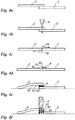
- a film web designated as a whole by 1 is intended to be connected with a similar film web, which is referred to below as 2, to form an overall film web.
- a silicone-coated paper 3 with the silicon-coated side at the top, laid so that the Do not stick foil ends to the substrate ( Fig. 2b ). (This step is optional.)
- the film web ends are now stretched and fixed on the substrate 4. This can be done for example with the aid of vacuum, if the substrate 4 has small (not shown in the figure) perforations through which the film web ends are sucked.
- the foil web ends can also be held on the lateral edges or edges with respect to their longitudinal extent and tensioned with the aid of a tensioning device, such as a tensioning bar.
- the clamping and fixing on the ground can also be done using electrostatic forces.
- vacuum, clamping bars or electrostatic forces can also be used together in combination.
- a hot stamping tool 5 in the present case shown as a lifting ram, alternatively a heating roller or a rolling ram, is pressed against the upper film web 2.
- the hot stamping tool is heated, and its heat is transferred to the upper film web 2, so that the adhesive layer 15 (or possibly in a cold stamping line, the primer layer 15) is activated, that is adhesive, so that the two film web ends of Film web 1 and 2 are glued together and adhere to each other.
- the hot stamping tool is brought to a temperature of 80 ° C to 140 ° C, z. B. of 110 ° C and applied over a period of 1 to 2 seconds. It is essential that only the adhesive layer 15 is activated, but not about the support sheet 11 is brought to melt or shrink. Preheating of the embossing point on the film web and / or the hot embossing tool by means of hot air or radiant heaters is possible before the hot embossing in order to be able to apply the hot embossing tool only relatively briefly when creating the connection.
- the upper film web is used in its capacity as an embossing film in order to establish the connection between the upper film web 2 and the lower film web 1.
- the silicone paper 3 is then removed, and there is a good connection between the two film webs 1 and 2 given.
- the tensile load is ensured in particular with a sufficiently thick carrier film 11 (between 12 and 20 ⁇ m, for example 19 ⁇ m thick) and a sufficient amount of adhesive in the adhesive layer 15.
- the adhesive layer 15 may be more than 5 ⁇ m thick (eg 8 ⁇ m). This corresponds to a same number of g / m 2 , for example 8 g / m 2 .
- the present first embodiment of the method has the advantage that is not contaminated in a subsequent hot stamping of the die.
- a cutting tool 6 is applied, for example, a knife, a razor blade, a cutter, a pair of scissors, a punching knife.
- a laser beam or ultrasonic waves could also be applied. The cutting under a certain angle of incidence of the cutting blade, the laser beam, etc. not equal to 90 ° relative to the surface of Film web is also possible, so that creates an oblique gate at the interface.
- the two film web ends of the film webs 1 and 2 are cut in particular at the same time, so that the film web ends are then in abutment.
- the remaining film web end pieces 16 and 26 are removed, see Figure 3c , When laying on impact, the two bevels can interlock with one another at an oblique angle.
- the lower film web 1 On the one sheet of film 1, which later acts as the lower film web 1, sprayed with the aid of a spray 7 7 adhesive 8.
- Other application options such as knife-coating, painting, printing are also possible.
- the lower layers can be manually, for. B. with the help of an adhesive tape, so removed (optional). If you place according to FIG. 3e the film web end of the film web 2 on the film web end of the film web 1 and then applied a hot stamping tool 5 as in Fig. 3f shown, the previously sprayed adhesive 8 is activated, and the two film webs 1 and 2 are glued together.
- FIGS. 4a to 4c correspond to the FIGS. 3a to 3c
- the glue will but not applied in liquid form, but in solid form by means of a carrier 9, see FIG. 4d
- the carrier 9 may have a base body 91, on the both sides of adhesive layers 92 and 93 of z. B. are applied between 1 micron and 6 microns thick.
- the adhesive layers may in turn be covered with a protective layer which is in FIG. 4d but already removed.
- a protective layer may be, for example, a thin silicone paper layer.
- the carrier 9 sticks to the film web 1 due to the presence of the adhesive layer 93.
- the upper adhesive layer 92 is exposed.
- the film web 2 set with its film web end on the carrier 9, so the film web 2 can glue by means of adhesive layer 92 to the support 9 and thus to the film web 1.
- this is also done by means of a hot stamping tool 5, by means of which the adhesive in the adhesive layers 92 and 93 is activated, cf. the arrows in FIG. 4f ,
- a fourth embodiment of the method according to the invention is in a modification of the embodiment according to the FIGS. 4a to 4f first proceeded as already FIG. 3a to FIG. 3c described.
- a support 9 'used which has a base 91, on which there is a lower adhesive layer 93, by means of which the carrier 9' to the film web 1 sticks.
- a silicone coating 94 between the main body 91 and the adhesive layer 93 is still located on the base body 91 FIG. 5e the film web 2 is set with its end on the carrier 9 '. If now a hot embossing tool 5 is applied ( FIG.
- the adhesive in the adhesive layer 93 is activated, see the bottom pointing down arrows.
- the transfer layer 14, 15 of the film web 2 on the top of the carrier 9 'coined see the upper downward arrows.
- the adhesive 93 has now been released from this carrier 9 ', but instead the transfer layer 95 of the film web end of the film web 2 is located on the upper side of the carrier 9'.
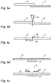
- a fifth embodiment of the method is initially according to Figure 6a to 6c proceeded as to the FIGS. 3a to 3c explained.
- a silicone-coated paper 3 ' is placed under the cut film web ends of the film web 1 and 2. This prevents the foil web ends 1 and 2 adhere to the ground.
- the film webs 1 and 2 repositioned so that the gap between them is minimal, less than 1 mm. Unlike that Hitherto described embodiments, no overlap between the film web ends is provided in the present fifth embodiment, but the film web ends abut each other, are "in shock".
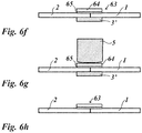
- a hot-melt adhesive tape 63 is positioned over the interface or joint.
- the hot-melt adhesive tape 63 comprises a PET carrier 64 and an adhesive layer 65.
- the PET carrier 64 is transparent and has a thickness of between 5 and 20 ⁇ m, e.g. B. of 12 microns.
- the adhesive layer 65 comprises a thermally activatable adhesive and is approximately 3 ⁇ m thick (between 2.5 and 3.5 ⁇ m). Overall, therefore, the hot-melt adhesive tape 63 is about 15 microns thick.
- a hot stamping tool 5 FIG. 6g
- the adhesive in the adhesive layer 65 is activated.
- the hot-melt adhesive tape 63 now adheres firmly to the film webs 1 and 2. After removal of the silicone paper 3 'is thus obtained according to FIG. 6h a firm connection between the film webs 1 and 2 through the hot-melt adhesive tape 63, which becomes an integral part of the entire film web.
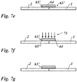
- the procedure is the same as in the fifth embodiment, but is on the Submitting a silicone paper 3 'omitted in the present case, and it is already without such a silicone paper repositioning according to FIG. 7d , see the arrows 71 and 72 after the film webs 1 and 2 are cut off at their ends.
- an adhesive tape 63 ' (see Figure 7e ) is applied to the interface, in the present case this adhesive tape comprises the same PET carrier 64 as the adhesive tape 63 according to FIG. 6f but on this one UV curable adhesive 65 '.
- step 7f instead of a hot embossing tool UV radiation, see the arrows 73, is irradiated, and a firm connection between the film webs 1 and 2 is provided, see FIG. 7g ,
- optical detection means such as a camera
- either the pattern located on the film webs is detected directly, such as by the optical detection means, and it is ensured by appropriate placement of the overlap, in the second to sixth method, in particular for setting the interface, that the remaining parts of the film webs 1 and 2 are exactly to each other.
- Registered accuracy means that corresponding pattern areas are each arranged at equal distances from each other, just above the splice point.
- register marks can be provided on this; These are such deliberately placed brands that serve for the placement of the film web in a further processing step, in the present case just when connecting two film webs 1 and 2 are considered together.
- Register marks can u. a. are also in the form of punched, which are then detected by a mechanical device or optically.
- the detection device sends measurement signals to a control device, and this then controls other devices or means suitable, so that the film web ends of the two film webs 1 and 2 are arranged in register with each other after the connection.
- a control device may be means for moving the foil web ends, and the movement is in response to signals obtained from the means for detecting the position.
- the film web ends can also be clamped appropriately or additionally suitably, by means for clamping, and finally the film web ends can also be cut by means for cutting in dependence on the measured values obtained in such a way that the patterns on the film webs are in register with one another.
- bonding takes place with the aid of a hot-melt adhesive.
- Composition Weight shares (from 1000) methyl ethyl ketone 380 toluene 400 Ethylene-vinyl acetate terpolymer (mp 66 ° C) 60 Ketone resin (mp 85-90 ° C) 80 Vinyl chloride / vinyl acetate copolymer (mp 80 ° C) 70 silica 10 4.
Landscapes
- Chemical & Material Sciences (AREA)
- Organic Chemistry (AREA)
- Chemical Kinetics & Catalysis (AREA)
- Lining Or Joining Of Plastics Or The Like (AREA)
- Decoration By Transfer Pictures (AREA)
- Replacement Of Web Rolls (AREA)
- Adhesive Tapes (AREA)
- Adhesives Or Adhesive Processes (AREA)
- Laminated Bodies (AREA)
- Folding Of Thin Sheet-Like Materials, Special Discharging Devices, And Others (AREA)
Description
- Die Erfindung betrifft ein Verfahren zum Verbinden einer ersten Folienbahn und einer zweiten Folienbahn, wobei die beiden Folienbahnen eine Transferfolie oder Laminierfolie bereitstellen und eine Trägerfolie und eine Dekorlage umfassen, wobei die Dekorlage insbesondere als (vollflächige) Metallschicht und/oder Farbschicht ausgebildet ist. Die Erfindung betrifft auch eine Folienbahn, wie sie durch das erfindungsgemäße Verfahren gebildet werden kann.
- Bei der Verarbeitung und Anwendung von Transferfolien und Laminierfolien müssen oftmals mehrere Folienbahnen miteinander verbunden werden, damit man eine entsprechend längere Gesamtlänge ("Lauflänge") erhält. Die Folienbahn liegt dann vorzugsweise aufgerollt auf einer Rolle ohne Unterbrechungen in der gewünschten Lauflänge vor.
- Je länger die so erzielte Folienbahn ist, in desto höherem Maße kann bei ihrem Einsatz eine hohe Produktivität erzielt werden. Auch werden Rüst- oder Standzeiten, die etwa mit einem Rollenwechsel einhergehen, verringert.
Ein bekanntes Verfahren zum Verbinden von Folienbahnen ist das so genannte "Spleißen", bei dem handelsübliche selbstklebende Klebebänder manuell angebracht werden, um zwei Folienbahnen zusammenzukleben. Die Verklebung erfolgt bei Laminier- oder Transferfolien (einseitig mit einer ablösbaren Transferlage beschichteten Folien) typischerweise auf der unbeschichteten Folienseite. Die Breite des Klebebandes liegt typischerweise im Bereich von zwischen 2 cm bis 5 cm. Die Klebebänder haben eine typische Dicke aus dem Bereich von ca. 30 µm bis 130 µm. Das zweiseitige Aufbringen von Klebebändern findet ebenfalls Anwendung. - Die
DE 10 2010 030 437 A1 offenbart einen Kaschierklebstoff zum Verbinden zweier Folienbahnen, wobei die Folienbahnen vollflächig miteinander verbunden werden. - Die
EP 2 216 279 A1 beschreibt ein Verfahren zum Heißsiegeln von Laminaten, die als Essensverpackung zum Einsatz kommen. - Das Spleißen mit Klebeband ist kostengünstig, kann mit einer relativ hohen Passergenauigkeit der Folienbahnen zueinander folgen, und der Spleiß (die Verbindungsstelle oder Verbindungsnaht) verfügt über hohe Festigkeiten, insbesondere Zugfestigkeit in Laufrichtung der Folienbahn. Die Zugfestigkeit in Laufrichtung der Folienbahn ist entscheidend, da während der Verarbeitung von Folienbahnen z. B. in Druckmaschinen, Kaschiermaschinen, Laminiermaschinen, Heißprägemaschinen, Kaltprägemaschinen die auftretenden Kräfte, insbesondere zum schnellen Transport der Folienbahn, in Laufrichtung auftreten.
- Beim Prägen von Einzelbildern sind diese Einzelbilder bzw. Motive (Nutzen) in einem bestimmten Layout auf der Folie angeordnet, in regelmäßigen Zeilen und Spuren. Die zu prägenden Nutzen liegen dabei in der Regel so nahe beieinander, dass das typischerweise verwendete Klebeband im Bereich der Prägezone liegen würde, also auch im Bereich des zu prägenden Nutzens. Die von dem Klebeband überdeckten Nutzen sind daher nicht prägbar und gehen verloren. Um Fehlprägungen und/oder Verschmutzungen der Prägestempel durch das Klebeband bzw. durch am Rand des Klebebands austretenden Klebstoff des Klebebandes zu vermeiden, wird der Spleiß deswegen detektiert, und es wird ein Folienvorschub durchgeführt, wodurch ein Materialverlust eintritt und die Produktivität vermindert wird. Um den Spleiß detektierbar zu machen, wird häufig ein farbiges und meist opakes (undurchsichtiges) Klebeband verwendet.
- Ein Nachteil von Spleißen besteht auch darin, dass wegen des verwendeten herkömmlichen Klebebandes der zu diesem gehörige Kaltkleber bei höherem Druck, etwa auch innerhalb einer gespleißten Folienrolle, herausgedrückt werden kann, sodass benachbarte Windungen der Rolle miteinander verklebt werden und die Rolle nicht mehr abwickelbar ist. Der innerhalb der Rolle so verteilte Kaltkleber verschmutzt außerdem eine Vielzahl von Stellen der Folienbahn, die dadurch eventuell nicht mehr verwendbar sind. Ein weiterer Nachteil besteht darin, dass die bisher zur Anwendung kommenden relativ dicken Klebebänder zu unerwünschten Markierungen und Abdrücken in den Folienrollen, insbesondere durch mehrere Folienlagen hindurch, führen, so dass zusätzlich Material der Folienbahn in der Nähe der Spleiße für die weitere Verarbeitung unbrauchbar werden kann.
- Aufgabe der vorliegenden Erfindung besteht darin, ein verbessertes Verfahren anzugeben, durch das die genannten Nachteile verringert oder vermieden werden.
- Erfindungsgemäß wird diese Aufgabe durch ein Verfahren zum Verbinden einer ersten Folienbahn und einer zweiten Folienbahn gelöst, wobei die beiden Folienbahnen eine Transferfolie bereitstellen und eine Trägerfolie und eine Dekorlage (insbesondere eine Metallschicht und/oder Farbschicht) umfassen, wobei vorgesehen ist, dass das Verbinden vermittels eines Klebstoffes erfolgt, der in einem Grundzustand bei Zimmertemperatur (20° C bei Atmosphärendruck von 1013 mbar) deaktiviert (bzw. nicht klebend) ist, und der durch Zufuhr von Wärme oder durch Zufuhr von Strahlung aktivierbar ist und bei dem Verfahren (entsprechend) aktiviert wird.
Die Dekorlage kann auch optisch wirksame Mikrostrukturen, beispielsweise diffraktive oder refraktive Strukturen wie z. B. Kinegram®, Hologram, Mattstrukturen, Beugungsstrukturen Nullter Ordnung oder auch Mikroprismen oder Mikrolinsen, aufweisen, deren Sichtbarkeit durch Metallschichten, Metallverbindungen oder sogenannte HRI-Schichten (HRI = High Refractive Index) insbesondere als Reflexionsschicht verstärkt wird. Zum Einsatz als Dekorlage können auch Mehrschichtsysteme, ein- oder mehrfarbig gedruckte Schichten, Schichten mit Magnetpigmenten usw. kommen. - Dadurch, dass vorliegend ein Heißklebstoff oder ein Reaktivklebstoff, insbesondere ein durch Strahlung härtbarer Klebstoff verwendet wird, wird der Nachteil im Stand der Technik vermieden, dass der Klebstoff unter Druck heraus gedrückt bzw. heraus gequetscht werden kann. Ein Heißklebstoff bewirkt auch einen besonders guten Halt, sodass mit vergleichsweise geringem Materialeinsatz an der Klebestelle die für eine Folienbahn erforderliche Zugfestigkeit erzielt werden kann. Der durch Strahlung härtbare Klebstoff ist bevorzugt ein mittels UV-Strahlen härtbarer Klebstoff, es sind aber auch andere Strahlen (blaues Licht, Ionenstrahlen etc.) grundsätzlich zur Härtung einsetzbar. Als Reaktivklebstoff sind alle Einkomponenten- und Mehrkomponenten-Reaktivklebstoffe einsetzbar. Derartige Heißklebstoffe oder UV-härtbare Klebstoffe sind bei Zimmertemperatur fest und nicht klebrig, sodass das erwähnte Herausdrücken oder Herausquetschen von Klebstoffmasse weitgehend vermieden wird und selbst kleinste überstehende Klebstoffreste nicht klebrig sind und innerhalb der aufgerollten Folienbahn und/oder beim Verarbeiten der Folienbahn (Heißprägen, Kaltprägen) keine Verschmutzungen verursachten.
- Die Erfindung beruht auf der Erkenntnis, dass beim erfindungsgemäßen Verbinden der ersten und zweiten Folienbahn keine Beeinträchtigung derselben erfolgt, auch wenn diese als Heißprägefolie ausgebildet sind. Insbesondere kann auch noch im Bereich einer Verbindungsstelle zwischen den Folienbahnenden aus der zuunterst liegenden Folienbahn oder an einer Nahtstelle aus beiden Folienbahnen geprägt werden, ohne dass das Vorhandensein der Verbindungsstelle an den geprägten Gegenständen in übermäßigem Maße erkennbar wäre. Es hat sich also gezeigt, dass die Qualität einer Prägung aus einem Bereich der Folienbahn mit Verbindungsstelle für sehr viele Anwendungsbereiche ausreichend ist, auch im Vergleich zu einer Prägung aus einem Bereich der Folienbahn ohne Verbindungsstelle.
- Erfindungsgemäß wird der Klebstoff auf einem gesonderten (von den Folienbahnen verschiedenen) bandförmigen oder sonstwie geeignet geformten Träger bereitgestellt. Hier wird an die Technik der Verwendung eines Klebebandes an sich angeknüpft, auch wenn ein Heißklebstoff oder strahlungshärtbarer Klebstoff eingesetzt wird. Das Bereitstellen des Klebstoffs auf einem Träger ist eine besonders komfortable Art und Weise, weil der Klebstoff zusammen mit dem Träger bevorratet werden kann.
- Der bandförmige Träger kann hierbei bevorzugt transparent sein und insbesondere aus einem Material bestehen, welches Polyethylenterephthalat (PET) oder Polyester umfasst. Als weitere mögliche Materialien für den bandförmigen Träger als auch für die Folienbahnen kommen in Betracht: Polyethylenterephthalat (PET), BOPP-Folien (BOPP = Biaxially Oriented Polypropylene), PET-G, PVC, PC, PP, PS, PEN, ABS, synthetisches Papier oder ein Laminatverbund von zwei oder mehreren solche Schichten (PET-G = PET mit Glycol; PVC = Polyvinylchlorid; PC = Polycarbonat; PP = Polypropylen; PS = Polystyrol; PEN = Polyethylennaphthalat; ABS = Acrylnitril-Butadien-Styrol-Copolymerisat). Aufgrund der Transparenz des bandförmigen Trägers lässt sich, auch wenn der Träger an der zusammengesetzten Folienbahn noch vorhanden sein sollte, durch den Träger hindurch ein Muster erkennen, um so passergenau auch im Bereich der Verbindungsstelle zwischen den Folienbahnen prägen zu können. Werden Kaltprägefolien als Folienbahnen miteinander verbunden, dann lässt sich beim Kaltprägen durch den transparenten bandförmigen Träger hindurch z. B. mit UV-Strahlung in ausreichender Stärke belichten.
- PET eignet sich in besonderer Weise für den bandförmigen Träger, weil auch die Folienbahnen typischerweise einen Träger aus PET umfassen.
- Dies lässt sich auch so formulieren, dass die Dehnungskoeffizienten eines an der Verbindungsstelle zwischen den Folienbahnen zu applizierenden bandförmigen Trägers und der Folienbahnen sich nicht mehr als 50 %, bevorzugt nicht mehr als 20 % und besonders bevorzugt nicht mehr als 10 % voneinander unterscheiden sollen, damit eine Verbindungsstelle besonders zugfest ist.
- Bei einer weiteren bevorzugten Ausführungsform weist der bandförmige Träger eine Dicke zwischen 5 µm und 50 µm, bevorzugt von zwischen 8 µm und 20µm, besonders bevorzugt von zwischen 10 µm und 15 µm auf. Die Klebstoffschicht darauf ist hierbei zwischen 1 µm und 5 µm dick, bevorzugt zwischen 2 µm und 3 µm dick.
- Bei den genannten geringen Dicken (etwa bei einer Dicke 12 µm mit Klebstoffschicht von 3 µm und insgesamt 15 µm) stört der bandförmige Träger beim Prägen kaum noch, selbst wenn er Teil der fertigen gesamten Folienbahn wird.
- Bei dem Verfahren, bei dem der Klebstoff auf einem Trägerband bereitgestellt wird, sind verschiedene Varianten möglich:
- Bei einer ersten Variante werden die beiden Folienbahnen vor einem Anbringen des bandförmigen Trägers derart geschnitten und positioniert, dass sie einander anstoßen (auf Stoß gebracht werden) und dass der bandförmige Träger auf die aneinander anstoßenden Enden der Folienbahnen überlappend aufgesetzt wird und sodann der Klebstoff aktiviert wird, sodass der bandförmige Träger auf beiden Folienbahnen klebt.
- Hier wird an die Technik der Verwendung eines herkömmlichen Klebebands mit Kaltklebstoff angeknüpft, aber wegen der vorliegenden Verwendung eines Heißklebstoffes oder strahlungshärtbaren Klebstoffs für einen besonders guten Halt bei vergleichsweise geringem Materialeinsatz gesorgt. Beispielsweise kann ein verbesserter Halt auch bei besonders dünnen bandförmigen Trägern (siehe die oben genannten geringen Werte für die Dicke) gewährleistet werden.
- Bevorzugt werden bei dieser Variante die beiden Folienbahnen zunächst einander überlappend gelegt, es wird im Bereich des Überlapps anschließend ein Schnitt durch beide Folienbahnen gesetzt (wobei der Schnitt insbesondere mit Hilfe eines Messers, einer Rasierklinge, eines Schneidrollers, einer Schere, eines Stanzmessers, mittels Lasers oder Ultraschall gesetzt wird), und nach dem Setzen des Schnitts werden die so entstehenden abgeschnittenen Folienbahnenden entfernt.
- Durch das Schneiden der Folienbahnen vor dem Verbinden kann insbesondere eine definierte Verbindungsstelle mehr oder weniger nahtlos geschaffen werden. Gegebenenfalls kann hier sogar für Passergenauigkeit im Bereich der Verbindungsstelle gesorgt werden, sodass man die Verbindung als solche gar nicht mehr feststellt. Unter Passergenauigkeit, auch Registergenauigkeit genannt, ist eine relative Lagegenauigkeit insbesondere der Verbindungsstellen zueinander zu verstehen. Die Lagegenauigkeit soll sich dabei innerhalb einer sehr geringen Toleranz bewegen, üblicherweise im zweistelligen, max. dreistelligen Mikrometer-Bereich. Der Begriff ist abgeleitet vom Begriff "Passer" bzw. "Passermarke", worunter eine optische Markierung zu verstehen ist, anhand derer eine Abweichung von der o. g. Toleranz optisch besonders gut erkennbar ist. Beispielsweise können Passermarken zwei überlappende Kreise, Kreuze, Dreiecke oder Kombinationen davon sein. Passermarken werden auch Registermarken genannt.
- Unter Abwandlung der ersten Variante können die Folienbahnen vor einem Anbringen des bandförmigen Trägers auch nach dem Schneiden so positioniert werden, dass sie leicht überlappen, um wenige Millimeter (z. B. zwischen 0,5 und 4 mm). In diesem Fall wird der bandförmige Träger auf die einander überlappenden Enden der Folienbahnen weiter überlappend aufgesetzt und sodann der Klebstoff aktiviert. Beim Aktivieren etwa durch Heißprägen des bandförmigen Trägers wird hierbei nicht nur der Klebstoff an dem bandförmigen Träger aktiviert sondern auch ggf. vorhandener Heißklebstoff des darunter liegenden Folienbandes. Vorteilhaft ist es, dass das überlappende Folienbahnende des unteren überlappenden Folienbahnendes an der Klebstoffschicht des oberen überlappenden Folienbahnendes angeklebt wird.
- Bei der ersten Variante auch in der genannten Abwandlung wird ferner bevorzugt ein mit Silikon beschichtetes blattförmiges Element mit sehr geringer oberflächlicher Adhäsion, insbesondere ein silikonbeschichtetes Papier(blatt), nach dem Schneiden und vor dem Positionieren unter die beiden Folienbahnenden gelegt. Dies ist insbesondere dann von Vorteil, wenn man es mit einem Heißklebstoff zu tun hat, der also unter Zufuhr von Wärme und Druck aktiviert wird. Dann verhindert das mit Silikon beschichtete Element bzw. Papier, dass die zusammengefügte Folienbahn auf einem Untergrund haftet. Bevorzugt erfolgt bei der vorgenannten ersten Variante (wie auch bei den nachfolgend genannten weiteren Varianten) das Aktivieren bei Verwendung eines Heißklebstoffes unter Einsatz eines translatorisch bewegbaren Hubstempel, einer rotatorisch bewegbaren Heizwalze, oder eines translatorisch und rotatorisch bewegbaren Abrollstempels. Diese Werkzeuge sind besonders vorteilhaft einsetzbar.
- Bei einer zweiten Variante des Verfahrens, bei dem ein Trägerband mit Klebstoff verwendet wird, trägt der bandförmige Träger beidseitig Klebstoff. Es werden die Folienbahnenden einander überlappend angeordnet und der bandförmige Träger wird im Bereich des Überlapps zwischen die Folienbahnenden gelegt. Gegebenenfalls wird vor der Positionierung des Trägers zwischen den Folienbahnenden von dem Träger noch ein Schutz zum Schutz der Klebstoffschicht, beispielsweise eine Silikonlage, entfernt. Anschließend wird der Klebstoff auf beiden Seiten des Trägers aktiviert, sodass der bandförmige Träger zwischen beiden Folienbahnenden klebt, sodass diese miteinander verbunden sind. Bei dieser Technologie ist für einen sehr zuverlässigen Halt und eine hohe Zugfestigkeit gesorgt.
- Bei einer dritten Variante der Ausführungsform mit nur auf seiner unteren Seite Klebstoff tragendem Trägerband werden die Folienbahnenden einander überlappend angeordnet, und der bandförmige Träger wird im Bereich des Überlapps zwischen die Folienbahnenden gelegt. Sodann wird mit Hilfe eines Heißprägewerkzeugs (Hubstempel, Heizwalze, Abrollstempel etc.) bewirkt, dass die Dekorlage der ersten Folienbahn auf den bandförmigen Träger, insbesondere seine obere Seite, übertragen wird und der Klebstoff sich von der unteren Seite des bandförmigen Trägers löst und auf die zweite Folienbahn übertragen wird. Anschließend wird der bandförmige Träger aus dem Überlapp herausgenommen, und sodann wird nochmals ein Heißprägewerkzeug (oder alternativ UV-Strahlung oder sonstige energiereiche Strahlen) verwendet, um die Folienbahnenden im Bereich des Überlapps aneinander zu kleben und somit miteinander zu verbinden. Die Seite der ersten Folienbahn mit entfernter Dekorlage weist zu der mit Klebstoff versehenen Seite der zweiten Folienbahn. Dabei wird nun der auf die zweite Folienbahn übertragene Klebstoff aktiviert, wobei die erste Folienbahn im Überlapp ohne Dekorlage mit Hilfe des Klebstoffs an der zweiten Folienbahn im Bereich des Überlapps fest haftet.
- Auf diese Weise erhält man an der Verbindungsstelle nur eine Dekorlage, nämlich die der zuunterst liegenden Folienbahn. Dadurch kann, wenn es sich bei der Folienbahn um eine Kaltprägefolie handelt, das Kaltprägen leichter durchgeführt werden, weil nicht durch die obere Dekorlage hindurch (UV-)Licht gelangen muss und dadurch zu stark abgeschwächt würde.
- Wie schon ausgeführt, eignet sich das erfindungsgemäße Verfahren in allen Ausführungsformen insbesondere für den Fall, dass die Folienbahnen, welche miteinander zu verbinden sind, eine Heißprägefolie oder eine Kaltprägefolie bereitstellen.
- Bei der bevorzugten Ausbildung des Verfahrens in allen Ausführungsformen wird beim Verbinden der Folienbahnen jeweils ein bzw. eine auf beiden Folienbahnen befindliche(s) Muster oder Markierung berücksichtigt, damit die jeweiligen Muster oder Markierungen passergenau bzw. lagegenau zueinander angeordnet sind. Auf diese Weise kann für eine Kontinuität der Muster oder Markierungen über die Verbindungsstelle zwischen den beiden Folienbahnen hinweg gesorgt werden. Es kann an bekannte Techniken zur Erfassung derartiger Muster oder Markierungen, z. B. mit optischen Sensoren und Kameras oder durch direkte Mustererfassung etwa von Passermarken bzw. Registermarken, angeknüpft werden.
- Das erfindungsgemäße Verfahren kann automatisch oder teilautomatisch oder manuell während der jeweiligen Verarbeitung oder Anwendung der Folienbahn, z. B. in einer Folienapplikationsmaschine oder in einer Folienherstellungsmaschine erfolgen. Dafür ist es vorteilhaft, wenn die Laufgeschwindigkeit der Folienbahn innerhalb der jeweiligen Maschine derartig verlangsamt wird, dass ein erfindungsgemäßes Verbinden der Folienbahnen erfolgen kann. Dabei wird die Laufgeschwindigkeit bevorzugt lediglich verlangsamt, jedoch ein vollständiger Stopp vermieden, sodass trotz des Spleißens eine kontinuierliche Verarbeitung der Folienbahn stattfinden kann. Nach dem Spleißen bzw. Verbinden der Folienbahnen kann wieder auf die ursprüngliche Laufgeschwindigkeit beschleunigt werden. Alternativ dazu ist es aber auch möglich, das erfindungsgemäße Verfahren bei stillstehender, also gestoppter Folienbahn durchzuführen oder in einer weiteren Alternative bei nicht verlangsamter, d. h. voller Laufgeschwindigkeit der jeweiligen Maschine.
- Ferner wird eine Vorrichtung zum Durchführen des Verfahrens beschrieben. Diese weist von einer Steuereinrichtung gesteuerte Mittel zum Bewegen und/oder Spannen und/oder Schneiden von Folienbahnenden zumindest einer von zwei Folienbahnen auf und eine Einrichtung zum Erfassen der Position von Mustern und/oder Markierungen, wobei die Steuereinrichtung ausgelegt ist, das Bewegen, Spannen und/oder Schneiden in Anhängigkeit von einer erfassten Position zu bewirken. Das Erfassen der Position kann optisch erfolgen.
- Durch die Vorrichtung wird somit die Durchführung des Verfahrens in der bevorzugten Variante ermöglicht, dass für eine Passergenauigkeit auch im Bereich der Verbindungsstelle zwischen den Folienbahnen gesorgt wird.
- Die Vorrichtung kann bevorzugt an einer Folienabwickeleinrichtung, beispielsweise in einer Druckmaschine oder Kaschiermaschine oder Laminiermaschine oder Heißprägemaschine oder Kaltprägemaschine angeordnet sein. Dort werden Folienbahnen der entsprechenden Maschine für die weitere Verarbeitung zugeführt. Es ist vorteilhaft, das Verbinden der Folienbahnen dort durchzuführen, sodass der weitere Verarbeitungsprozess so wenig wie möglich gestört wird bzw. in diesen Verarbeitungsprozess so wenig wie möglich eingegriffen werden muss. Eine Geschwindigkeitsregelung der Folienabwickeleinrichtung ist so ebenfalls besonders einfach möglich. So kann die Folienabwickeleinrichtung mit einfachen Mitteln verlangsamt oder gestoppt werden, um das Verbinden der Folienbahnen zu erleichtern, und kann nach dem erfolgten Verbinden der Folienbahnen ebenso einfach wieder beschleunigt oder gestartet werden. Beispielsweise geschieht dies durch eine sowieso vorhandene elektronische Motorsteuerung, die gegebenenfalls auch andere Antriebe oder Verarbeitungsmodule der jeweiligen Maschine ansteuern kann, um die sich ändernde Verarbeitungsgeschwindigkeit zu synchronisieren. Ebenso kann die Vorrichtung an einer Folienherstellungsmaschine eingesetzt werden, um die dort hergestellten Folien in ihrer Lauflänge an bestimmte Erfordernisse anzupassen. So können z. B. einzelne Folienbahnen unterschiedlicher, getrennter Produktionsläufe zu einer gemeinsamen Folienbahn auf einer gemeinsamen Rolle verbunden werden. Dies kann insbesondere dafür erfolgen, um eine weitere Verarbeitung der Folienbahn zu erleichtern.
- Die Aufgabe wird ferner durch das Bereitstellen einer Folienbahn gelöst, welche in einem ersten Aspekt eine Trägerfolie und eine Dekorlage (insbesondere Metallschicht und/oder Farbschicht) umfasst und aus zumindest zwei Teilfolienbahnen zusammengesetzt ist, die an zwei jeweiligen Teilfolienbahnenden miteinander mittels eines beim Verbinden durch Zufuhr von Wärme oder durch Zufuhr von Strahlung (ultraviolettes Licht, blaues Licht, Ionen etc.) aktivierten Klebstoffs verbunden sind.
- Eine solche Folienbahn ist durch Anwendung des erfindungsgemäßen Verfahrens erhältlich.
Die Aufgabe wird auch in einem zweiten Aspekt durch eine Folienbahn gelöst, die eine Trägerfolie und eine Dekorlage (insbesondere Metallschicht und/oder Farbschicht) umfasst, und aus zumindest zwei Teilfolienbahnen zusammengesetzt ist, welche an zwei jeweiligen Teilfolienbahnenden miteinander durch ein (insbesondere transparentes) Band, vorzugsweise aus einem Material, das Polyethylenterephthalat (PET) umfasst, in einer Dicke von zwischen 5 µm und 100 µm, bevorzugt zwischen 10 µm und 15 µm miteinander verbunden sind. Die zuletzt genannte Folienbahn kann insbesondere die Eigenschaften der zuerst genannten Folienbahn umfassen. - Bei der Folienbahn gemäß dem zweiten Aspekt wird ein relativ dünnes transparentes Band im Verbindungsbereich zwischen den Teilfolienbahnen bereitgestellt. Dies wird insbesondere dadurch ermöglicht, dass das erfindungsgemäße Verfahren eingesetzt wird, das sich auf diese Ausführungsform bezieht. Insbesondere in Verbindung mit dem ersten Aspekt (Heißklebstoff oder strahlungshärtbarer Klebstoff) kann hierbei an der Verbindungsstelle eine ausreichende Zugfestigkeit bereitgestellt werden.
- Nachfolgend werden bevorzugte Ausführungsformen der Erfindung und der Bezug auf Zeichnung näher erläutert, in der
- Fig. 1
- den Aufbau einer Folienbahn veranschaulicht, die mit einer gleichartigen Folienbahn zu einer Gesamtfolienbahn verbunden werden soll;
- Fig. 2a bis 2c
- zur Erläuterung der Schritte einer ersten Ausführungsform des erfindungsgemäßen Verfahrens dienen;
- Fig. 3a bis 3f
- zur Erläuterung der Schritte einer zweiten Ausführungsform des erfindungsgemäßen Verfahrens dienen;
- Fig. 4a bis 4f
- zur Erläuterung der Schritte einer dritten Ausführungsform des erfindungsgemäßen Verfahrens dienen;
- Fig. 5a bis 5h, 5j, 5k
- zur Erläuterung der Schritte einer vierten Ausführungsform des erfindungsgemäßen Verfahrens dienen;
- Fig. 6a bis 6h
- zur Erläuterung der Schritte einer fünften Ausführungsform des erfindungsgemäßen Verfahrens dienen;
- Fig. 7a und 7g
- zur Erläuterung der Schritte einer sechsten Ausführungsform des erfindungsgemäßen Verfahrens dienen;
- Eine im Ganzen mit 1 bezeichnete Folienbahn soll mit einer gleichartigen Folienbahn, die nachfolgend mit 2 bezeichnet wird, zu einer Gesamtfolienbahn verbunden werden.
- Die Folienbahnen haben jeweils einen Schichtaufbau, wie er in
Figur 1 erläutert ist: - Auf einer jeweiligen Oberseite befindet sich eine Trägerfolie 11, z. B. Polyethylenterephthalat (PET) in einer Schichtdicke von zwischen 5 µm und 500 µm. Auf der Trägerfolie 11 befindet sich eine Ablöseschicht 12, die dazu dient, die weiteren Schichten 13, 14, 15 leichter von der Trägerfolie 11 ablösen zu können. Beispielsweise besteht die Ablöseschicht aus einem Wachs. Die Schicht 13 ist eine Schutzschicht und besteht beispielsweise aus Acrylatlack oder Acrylatlack-Gemisch, thermisch trocknend und/oder UV-gehärtet. Auf die Schutzschicht 13 folgt eine Metallschicht 14, z. B. aus Aluminium oder Chrom oder Kupfer. Die äußerste, zu unterst liegende Schicht 15 ist eine Kleberschicht aus einem vorzugsweise wärmeaktivierbaren Kleber, wenn es sich bei der Folienbahn 1 um eine Heißprägefolie handeln soll. Die Schicht 15 ist eine so genannte Haftvermittler- oder Primerschicht aus einem vorzugsweise wärmeaktivierbaren Kleber, die mit einem (UV-härtbaren) Klebstoff zusammenwirken kann, wenn es sich bei der Folienbahn 1 um eine Kaltprägefolie handelt.
- Bei einer ersten Ausführungsform des Verfahrens werden zunächst die beiden Folienbahnen 1 und 2 mit ihren Folienbahnenden einander überlappend gelegt (
Fig. 2a ). Unter die Folienbahnenden wird ein mit Silikon beschichtetes Papier 3, mit der mit Silikon beschichteten Seite zuoberst, gelegt, damit die Folienbahnenden nicht am Untergrund haften (Fig. 2b ). (Dieser Schritt ist optional.) - Die Folienbahnenden werden nun gespannt und auf dem Untergrund 4 festgelegt. Dies kann beispielsweise unter Zuhilfenahme von Vakuum erfolgen, wenn der Untergrund 4 kleine (nicht in der Figur gezeigte) Perforationen aufweist, durch die die Folienbahnenden angesogen werden. Die Folienbahnenden können auch an den bezüglich ihrer Längserstreckung seitlichen Ecken bzw. Kanten festgehalten und mit Hilfe einer Spannvorrichtung wie etwa eines Spannbalkens gespannt werden. Das Spannen und Festlegen auf dem Untergrund kann ferner auch unter Nutzung elektrostatischer Kräfte erfolgen. Schließlich können Vakuum, Spannbalken oder elektrostatische Kräfte auch miteinander in Kombination eingesetzt werden.
- Wesentlich ist, dass bei der Anordnung gemäß
Figur 2b die Folienenden so fest liegen bzw. gehalten sind, dass sie bei einer äußeren Krafteinwirkung, wie nachfolgend vorgesehen, ihre Lage nicht oder nur unwesentlich verändern. Im anschließenden Schritt (Fig. 2c ) wird ein Heißprägewerkzeug 5, vorliegend gezeigt als Hubstempel, alternativ eine Heizwalze oder ein Abrollstempel, gegen die obere Folienbahn 2 gedrückt. Hierbei wird, wie beim Heißprägen üblich, das Heißprägewerkzeug erwärmt, und seine Wärme wird auf die obere Folienbahn 2 übertragen, sodass die Klebstoffschicht 15 (oder ggf. bei einer Kaltprägebahn die Primerschicht 15) aktiviert wird, also klebend wird, sodass die beiden Folienbahnenden der Folienbahn 1 und 2 miteinander verklebt werden und aneinander haften.
Das Heißprägewerkzeug wird auf eine Temperatur von 80° C bis 140° C gebracht, z. B. von 110° C und über eine Zeitdauer von 1 bis 2 Sekunden appliziert. Wesentlich ist, dass lediglich die Klebstoffschicht 15 aktiviert wird, nicht aber etwa die Trägerfolie 11 zum Schmelzen oder Schrumpfen gebracht wird. Vor dem Heißprägen ist ein Vorwärmen der Prägestelle auf der Folienbahn und/oder des Heißprägewerkzeugs mittels Heißluft oder Heizstrahlern möglich, um beim Schaffen der Verbindung das Heißprägewerkzeug nur relativ kurz applizieren zu können. Man nutzt die obere Folienbahn in ihrer Eigenschaft als Prägefolie, um die Verbindung zwischen der oberen Folienbahn 2 und der unteren Folienbahn 1 herzustellen. - Das Silikonpapier 3 wird anschließend entfernt, und es ist eine gute Verbindung zwischen den beiden Folienbahnen 1 und 2 gegeben. Die Zugbelastung ist insbesondere bei ausreichend dicker Trägerfolie 11 (zwischen 12 und 20 µm, z. B. 19 µm dick) und einer ausreichenden Menge an Klebstoff in der Klebstoffschicht 15 gewährleistet. Beispielsweise kann die Klebstoffschicht 15 mehr als 5 µm dick sein (z. B. 8 µm). Dies entspricht einer selben Zahl von g/m2, also beispielsweise 8 g/m2.
- Die vorliegend erste Ausführungsform des Verfahrens hat den Vorteil, dass bei einem nachfolgenden Heißprägen der Prägestempel nicht verschmutzt wird.
- Bei einer zweiten Ausführungsform des Verfahrens werden zunächst gemäß
Figur 3a die Folienbahnenden der Folienbahn 1 und 2 wieder auf Überlapp gelegt. Sodann werden die Folienbahnenden auf die oben beschriebene Art und Weise gespannt und auf dem Untergrund festgelegt. Wie inFigur 3b gezeigt, wird sodann ein Schneidwerkzeug 6 appliziert, beispielsweise ein Messer, eine Rasierklinge, ein Schneidroller, eine Schere, ein Stanzmesser. Alternativ könnten auch ein Laserstrahl oder Ultraschallwellen appliziert werden. Das Schneiden unter einem bestimmten Anstellwinkel des Schneidmessers, des Laserstrahls usw. ungleich 90° relativ zur Oberfläche der Folienbahn ist ebenfalls möglich, sodass an der Schnittstelle ein schräger Anschnitt entsteht.
Die beiden Folienbahnenden der Folienbahnen 1 und 2 werden insbesondere gleichzeitig geschnitten, sodass die Folienbahnenden dann auf Stoß liegen. Die verbleibenden Folienbahnendstücke 16 und 26 werden entfernt, sieheFigur 3c . Beim Legen auf Stoß können bei einem schrägen Anschnitt die beiden Schrägen ineinander greifen. - Sodann wird auf die eine Folienbahn 1, die später als untere Folienbahn 1 fungiert, mithilfe eines Sprühwerkzeugs 7 Klebstoff 8 aufgesprüht. Andere Aufbringungsmöglichkeiten wie Aufrakeln, Aufstreichen, Aufdrucken sind ebenfalls möglich. Von der anderen Folienbahn 2 können die unteren Schichten manuell, z. B. mithilfe eines Klebebandes, entfernt, also abgezogen werden (optional). Legt man nun gemäß
Figur 3e das Folienbahnende von der Folienbahn 2 auf das Folienbahnende der Folienbahn 1 und appliziert sodann ein Heißprägewerkzeug 5 wie inFig. 3f gezeigt, so wird der zuvor aufgesprühte Klebstoff 8 aktiviert, und die beiden Folienbahnen 1 und 2 werden miteinander verklebt. - Insbesondere, wenn die Transferlagen des Folienbahnendes der Folienbahn 2 manuell entfernt werden, hat man auf der fertigen Folienbahn im Bereich der Verbindungsstelle nur noch eine Metallschicht (als Teil der Dekorlage der Folienbahn 2), sodass insbesondere eine UV-Belichtung beim Kaltprägen im Spleißbereich erleichtert ist.
- Bei einer dritten Ausführungsform des Verfahrens werden zunächst dieselben Schritte durchgeführt wie bei der zweiten Ausführungsform des Verfahrens, die
Figuren 4a bis 4c entsprechen denFiguren 3a bis 3c . Der Klebstoff wird vorliegend aber nicht in flüssiger Form aufgebracht, sondern in fester Form mithilfe eines Trägers 9, sieheFigur 4d . Der Träger 9 kann einen Grundkörper 91 aufweisen, auf dem beidseitig Klebstoffschichten 92 und 93 von z. B. zwischen 1 µm und 6 µm Dicke aufgebracht sind. Die Klebstoffschichten können ihrerseits mit einer Schutzschicht abgedeckt sein, die inFigur 4d allerdings bereits entfernt ist. Eine solche Schutzschicht kann beispielsweise eine dünne Silikonpapier-Schicht sein. - Bei der Situation gemäß
Figur 4d klebt der Träger 9 wegen des Vorhandenseins der Klebstoffschicht 93 auf der Folienbahn 1. Die obere Klebstoffschicht 92 ist freiliegend. Wird nun gemäßFigur 4e die Folienbahn 2 mit ihrem Folienbahnende auf den Träger 9 gesetzt, so kann auch die Folienbahn 2 mittels Klebstoffschicht 92 an dem Träger 9 und damit an der Folienbahn 1 kleben. Dies erfolgt vorliegend ebenfalls mithilfe eines Heißprägewerkzeuges 5, durch das der Klebstoff in den Klebstoffschichten 92 und 93 aktiviert wird, vgl. die Pfeile inFigur 4f . - Bei einer vierten Ausführungsform des erfindungsgemäßen Verfahrens wird in Abwandlung der Ausführungsform gemäß den
Figuren 4a bis 4f zunächst vorgegangen wie schon zuFigur 3a bis Figur 3c beschrieben. Es wird nun allerdings ein Träger 9' eingesetzt, der einen Grundkörper 91 aufweist, auf dem sich eine untere Klebstoffsschicht 93 befindet, mithilfe der der Träger 9' an der Folienbahn 1 klebt. Auf dem Grundkörper 91 befindet sich nun jedoch weiterhin eine Silikonbeschichtung 94 zwischen dem Grundkörper 91 und der Klebstoffschicht 93 Es wird nun auch hier gemäßFigur 5e die Folienbahn 2 mit ihrem Ende auf den Träger 9' gesetzt. Wird nun ein Heißprägewerkzeug 5 appliziert (Figur 5f ), so wird zwar einerseits der Klebstoff in der Klebstoffschicht 93 aktiviert, siehe die unteren nach unten weisenden Pfeile. Gleichzeitig wird jedoch die Transferlage 14, 15 der Folienbahn 2 auf die Oberseite des Trägers 9' geprägt, siehe die oberen nach unten weisenden Pfeile. Wie anhand vonFigur 5g zu erkennen, kann man anschließend den Träger 9' entfernen. Von diesem Träger 9' hat sich nunmehr der Klebstoff 93 gelöst, dafür aber befindet sich die Transferlage 95 des Folienbahnendes der Folienbahn 2 auf der Oberseite des Trägers 9'. - Nach dem Entfernen des Trägers 9' kann man nun die Folienbahn 2 mit ihrem Folienbahnende auf die Folienbahn 1 legen, siehe
Figur 5g , und wenn anschließend mithilfe eines Heißprägewerkzeuges 5 die Klebstoffschicht 93 aktiviert wird (Fig. 5h ), kommt es zu einer Klebeverbindung gemäßFigur 5k . - Bei dieser Ausführungsform ist in erhöhtem Maße gewährleistet, dass im Bereich der Verbindungsstelle (Spleißbereich) nur eine Metallschicht vorhanden ist, nämlich die Metallschicht der Transferlage der unteren Folienbahn 1. Dadurch kann insbesondere beim Kaltprägen auch eine UV-Aktivierung des Klebstoffs der unteren Folienbahn 1 durch die Metallschicht hindurch erfolgen. Beim Heißprägen der unteren Folienbahn 1 ist dafür gesorgt, dass der Heißklebstoff der unteren Folienbahn 1 den Heißprägestempel nicht verschmutzt.
- Bei einer fünften Ausführungsform des Verfahrens wird zunächst gemäß
Figur 6a bis 6c vorgegangen wie zu denFiguren 3a bis 3c erläutert. Nun wird ein mit Silikon beschichtetes Papier 3' unter die abgeschnittenen Folienbahnenden der Folienbahn 1 und 2 gelegt. Dadurch wird verhindert, dass die Folienbahnenden 1 und 2 am Untergrund haften. Optional werden nun gemäßFigur 6e , siehe die Pfeile 61 und 62, die Folienbahnen 1 und 2 nachpositioniert, damit der dazwischenliegende Spalt minimal ist, weniger als 1 mm. Anders als bei dem bisher beschriebenen Ausführungsformen ist bei der vorliegenden fünften Ausführungsform kein Überlapp zwischen den Folienbahnenden mehr vorgesehen, sondern die Folienbahnenden stoßen einander an, liegen "auf Stoß".
GemäßFigur 6f wird nun ein Heißklebeband 63 über der Schnittstelle bzw. Stoßstelle positioniert. - Das Heißklebeband 63 umfasst einen PET-Träger 64 und eine Klebstoffschicht 65. Der PET-Träger 64 ist transparent und hat eine Dicke von zwischen 5 und 20 µm, z. B. von 12 µm. Die Klebstoffschicht 65 umfasst vorliegend einen thermisch aktivierbaren Klebstoff und ist ca. 3 µm dick (zwischen 2,5 und 3,5 µm). Insgesamt ist somit das Heißklebeband 63 ca. 15 µm dick. Sodann wird ein Heißprägewerkzeug 5 (
Figur 6g ) appliziert und der Klebstoff in der Klebstoffschicht 65 aktiviert. Dadurch klebt das Heißklebeband 63 nunmehr fest an den Folienbahnen 1 und 2. Nach Entfernung des Silikonpapiers 3' erhält man somit gemäßFigur 6h eine feste Verbindung zwischen den Folienbahnen 1 und 2 durch das Heißklebeband 63, das integraler Bestandteil der gesamten Folienbahn wird. - Durch das Vermeiden eines Überlapps ist es in verstärktem Maße ermöglicht, auch im Bereich der Verbindungsstelle (Spleißbereich) zu prägen. Dies gilt im besonderen Maße für Kaltprägen. Wegen der geringen Dicke des Heißklebebandes 63 sowie des nicht vorhandenen Überlapps der Folienbahnen 1 und 2 durch Ihre Positionierung "auf Stoß" macht sich die Spleißstelle auf der fertigen Folienbahn auch kaum in störender Art und Weise bemerkbar.
- Bei einer sechsten Ausführungsform des Verfahrens wird zunächst vorgegangen wie bei der fünften Ausführungsform, allerdings wird auf das Unterlegen eines Silikonpapiers 3' vorliegend verzichtet, und es erfolgt bereits ohne ein solches Silikonpapier das Nachpositionieren gemäß
Figur 7d , siehe die Pfeile 71 und 72, nachdem die Folienbahnen 1 und 2 an ihren Enden abgeschnitten sind.
Auch hier wird ein Klebeband 63' (sieheFigur 7e ) auf die Schnittstelle aufgelegt, vorliegend umfasst dieses Klebeband denselben PET-Träger 64 wie das Klebeband 63 gemäßFigur 6f , allerdings auf diesem einen mit UV-Strahlung härtbaren Klebstoff 65'. - Entsprechend wird in Schritt 7f anstatt eines Heißprägewerkzeugs UV-Strahlung, siehe die Pfeile 73, eingestrahlt, und es wird eine feste Verbindung zwischen den Folienbahnen 1 und 2 geschaffen, siehe
Figur 7g . - Bei allen genannten Verfahren kann durch Einsatz geeigneter Erfassungsmittel, z. B. optischer Erfassungsmittel wie etwa einer Kamera, dafür gesorgt werden, dass die Folienbahnen 1 und 2 passergenau miteinander verbunden werden, damit ein auf den Folienbahnen 1 und 2 befindliches Muster sich gewissermaßen kontinuierlich über die Spleißstelle hinweg fortsetzt.
- Hierbei wird entweder das auf den Folienbahnen befindliche Muster unmittelbar erfasst, etwa durch die optischen Erfassungsmittel, und es wird durch geeignete Platzierung des Überlapps, bei dem zweiten bis sechsten Verfahren insbesondere zur Setzung der Schnittstelle, dafür gesorgt, dass die verbleibenden Teile der Folienbahnen 1 und 2 passergenau zueinander liegen. Passergenau bedeutet, dass einander entsprechende Musterbereiche jeweils in gleichen Abständen voneinander angeordnet sind, eben auch über die Spleißstelle hinweg.
- Statt einer direkten Erfassung eines Musters auf den Folienbahnen können auf diesen auch Registermarken vorgesehen sein; es handelt sich hierbei um solche bewusst gesetzten Marken, die zur Platzierung der Folienbahn bei einem weiteren Bearbeitungsschritt dienen, vorliegend eben bei dem Verbinden zweier Folienbahnen 1 und 2 miteinander berücksichtigt werden. Registermarken können u. a. auch in Form von Ausstanzungen vorliegen, die dann durch eine mechanische Einrichtung oder auch optisch erfasst werden.
- In der entsprechenden Vorrichtung sendet die Erfassungseinrichtung Messsignale an eine Steuereinrichtung, und diese steuert dann andere Einrichtungen bzw. Mittel geeignet an, damit die Folienbahnenden der beiden Folienbahnen 1 und 2 nach Herstellung der Verbindung passergenau zueinander angeordnet sind. Beispielsweise kann es sich um Mittel zum Bewegen der Folienbahnenden handeln, und die Bewegung erfolgt in Abhängigkeit von von der Einrichtung zum Erfassen der Position gewonnenen Signalen. Genauso können die Folienbahnenden auch alternativ oder zusätzlich geeignet gespannt werden, durch Mittel zum Spannen, und schließlich können die Folienbahnenden auch durch Mittel zum Schneiden in Abhängigkeit von den gewonnenen Messwerten so geschnitten werden, dass die Muster auf den Folienbahnen passergenau zueinander zu liegen kommen.
- Mit Ausnahme der sechsten Ausführungsform erfolgt vorliegend das Verbinden mithilfe eines Heißklebestoffs.
- Es gibt verschiedene Ansatzpunkte, welche Zusammensetzung dieser Heißklebstoff haben kann (Fp = Flammpunkt; Tg = Glasübergangstemperatur):
1. Zusammensetzung Gewichtsanteile (von 7500) Toluol 2000 Aceton 2100 Hochmolekulares Ethylmethacrylat Tg 60 °C 300 Methacrylatcopolymer Tg 40°C - 80°C 700 Thermoplastisches Polyvinylacetat Tg 80°C - 83°C 200 Ethanol 2100 Hochdisperse Kieselsäure 100 2. Zusammensetzung Gewichtsanteile (von 1030) Methylethylketon 280 Toluol 350 PVC/PVAC-Copolymer (Fp 80 °C) 210 Thermoplastisches Polyurethan (Dichte = 1,18 g/cm3) 130 Kieselsäure, hydrophobiert (Partikelgröße ca. 10 µm) 60 3. Zusammensetzung Gewichtsanteile (von 1000) Methylethylketon 380 Toluol 400 Ethylen-Vinylacetat-Terpolymer (Fp 66°C) 60 Ketonharz (Fp 85-90°C) 80 Vinylchlorid-/Vinylacetat-Copolymer (Fp 80°C) 70 Siliciumdioxid 10 4. Zusammensetzung Gewichtsanteile (von 1000) Methylethylketon 550 Ethylacetat 175 Cyclohexanon 50 Polyurethanharz (Fp > 200°C) 100 Polyvinylchlorid Terpolymer (Tg = 90°C) 120 Siliciumdioxid 5 - Allen genannten Ausführungsformen des Verfahrens ist gemeinsam, dass die eigentliche Transferlage durch das Schaffen der Verbindung auch im Spleißbereich nicht bzw. allenfalls unwesentlich beeinträchtigt wird, sodass auch im Spleißbereich geprägt werden kann.
Claims (10)
- Verfahren zum Verbinden von Folienbahnenden einer ersten Folienbahn (1) und einer zweiten Folienbahn (2), wobei die beiden Folienbahnen eine Transferfolie bereitstellen und eine Trägerfolie (11) und eine Dekorlage, insbesondere Metallschicht und/oder Farbschicht (14), umfassen,
wobei das Verbinden mittels eines Klebstoffs (15, 8, 92, 93, 65, 65') erfolgt, der in einem Grundzustand bei Zimmertemperatur deaktiviert ist und durch Zufuhr von Wärme oder durch Zufuhr von Strahlung aktivierbar ist und bei dem Verfahren aktiviert wird und wobei der Klebstoff auf einem gesonderten bandförmigen Träger (9, 9', 63, 63') bereitgestellt wird. - Verfahren nach Anspruch 1, bei dem der bandförmige Träger bevorzugt transparent ist und insbesondere aus Material besteht, welches Polyethylenterephthalat (PET) umfasst.
- Verfahren nach einem der Ansprüche 1 oder 2, bei dem der bandförmige Träger eine Dicke von zwischen 5 µm und 100 µm, bevorzugt von zwischen 8 µm und 20 µm, besonders bevorzugt zwischen 10 µm und 15 µm aufweist und die Klebstoffschicht darauf zwischen 1µm und 5µm dick, bevorzugt zwischen 2 µm und 3 µm dick ist.
- Verfahren nach einem der vorangehenden Ansprüche, bei dem die beiden Folienbahnen vor einem Anbringen des bandförmigen Trägers (63, 63') derart geschnitten und positioniert werden, dass sie aneinander anstoßen, und dass der bandförmige Träger (63, 63') auf die einander anstoßenden Enden der Folienbahnen (1, 2) aufgesetzt wird und sodann der Klebstoff (65, 65') aktiviert wird, sodass der bandförmige Träger (63, 63') auf beiden Folienbahnen (1, 2) klebt, wobei bevorzugt die beiden Folienbahnen (1, 2) einander überlappend gelegt werden und im Bereich des Überlapps ein Schnitt durch beide Folienbahnen gesetzt wird, insbesondere mithilfe eines Messers, einer Rasierklinge, eines Schneidrollers, einer Schere, eines Stanzmessers, mittels eines Lasers oder Ultraschalls gesetzt wird, und bei dem die so entstehenden abgeschnittenen Folienbahnenden (16, 26) entfernt werden.
- Verfahren nach einem der Ansprüche 1 bis 3, bei dem der bandförmige Träger (9) beidseitig Klebstoff (92, 93) trägt und die Folienbahnenden einander überlappend angeordnet werden und der bandförmige Träger (9) im Bereich des Überlapps zwischen die Folienbahnenden gelegt wird und sodann der Klebstoff aktiviert wird, sodass der bandförmige Träger (9) zwischen beiden Folienbahnenden klebt.
- Verfahren nach einem der Ansprüche 1 bis 3, bei dem die Folienbahnenden einander überlappend angeordnet werden und der bandförmige Träger (9') im Bereich des Überlapps zwischen die Folienbahnenden gelegt wird und mithilfe eines Heißprägewerkzeugs (5) bewirkt wird, dass die Dekorlage (14) der ersten Folienbahn (2) auf den bandförmigen Träger (9') übertragen wird und sich der Klebstoff (93) von dem bandförmigen Träger (9') löst und auf die zweite Folienbahn (1) übertragen wird, dass anschließend der bandförmige Träger (9') herausgenommen wird und sodann nochmals ein Heißprägewerkzeug (5) oder Strahlung appliziert wird, sodass die Folienbahnenden im Bereich des Überlapps aneinander kleben.
- Verfahren nach einem der vorhergehenden Ansprüche, bei dem die Folienbahnen (1, 2) eine Heißprägefolie oder eine Kaltprägefolie bereitstellen.
- Verfahren nach einem der vorhergehenden Ansprüche, bei dem beim Verbinden der Folienbahnen jeweils zumindest ein bzw. eine auf beiden Folienbahnen befindliche(s) Muster oder Markierung berücksichtigt wird, damit die jeweiligen Muster oder Markierungen passergenau zueinander angeordnet sind.
- Folienbahn, umfassend eine Trägerfolie (11) und eine Dekorlage, insbesondere Metallschicht und/oder Farbschicht (14), und zusammengesetzt aus zumindest zwei Teilfolienbahnen (1, 2), die als Transferfolie ausgebildet sind und die an zwei jeweiligen Teilfolienbahnenden miteinander mittels eines beim Verbinden durch Zufuhr von Wärme oder durch Zufuhr von Strahlung aktivierten Klebstoffs (15, 8, 92, 93, 65, 65') verbunden sind.
- Folienbahn nach Anspruch 9, umfassend eine Trägerfolie (11) und eine Dekorlage, insbesondere Metallschicht und/oder Farbschicht (14), und zusammengesetzt aus zumindest zwei Teilfolienbahnen (1, 2), die an zwei jeweiligen Teilfolienbahnenden durch ein, insbesondere transparentes, Band (63, 63'), vorzugsweise aus Material, welches Polyethylen umfasst, in einer Dicke von zwischen 8 und 20 µm, bevorzugt von zwischen 10 und 15 µm, miteinander verbunden sind.
Applications Claiming Priority (2)
| Application Number | Priority Date | Filing Date | Title |
|---|---|---|---|
| DE102012103586A DE102012103586A1 (de) | 2012-04-24 | 2012-04-24 | Verfahren und Vorrichtung zum Verbinden einer ersten Folienbahn und einer zweiten Folienbahn |
| PCT/EP2013/057993 WO2013160170A1 (de) | 2012-04-24 | 2013-04-17 | Verfahren und vorrichtung zum verbinden einer ersten folienbahn und einer zweiten folienbahn |
Publications (2)
| Publication Number | Publication Date |
|---|---|
| EP2841515A1 EP2841515A1 (de) | 2015-03-04 |
| EP2841515B1 true EP2841515B1 (de) | 2017-03-22 |
Family
ID=48141984
Family Applications (1)
| Application Number | Title | Priority Date | Filing Date |
|---|---|---|---|
| EP13717269.8A Active EP2841515B1 (de) | 2012-04-24 | 2013-04-17 | Verfahren und vorrichtung zum verbinden von folienenden einer ersten folienbahn und einer zweiten folienbahn |
Country Status (13)
| Country | Link |
|---|---|
| US (1) | US20150050444A1 (de) |
| EP (1) | EP2841515B1 (de) |
| JP (1) | JP6384734B2 (de) |
| KR (1) | KR102071091B1 (de) |
| CN (1) | CN104302721B (de) |
| DE (1) | DE102012103586A1 (de) |
| ES (1) | ES2623783T3 (de) |
| IN (1) | IN2014KN02302A (de) |
| MX (1) | MX365932B (de) |
| MY (1) | MY167605A (de) |
| PL (1) | PL2841515T3 (de) |
| TW (1) | TWI610797B (de) |
| WO (1) | WO2013160170A1 (de) |
Families Citing this family (16)
| Publication number | Priority date | Publication date | Assignee | Title |
|---|---|---|---|---|
| EP3145465B1 (de) * | 2014-05-22 | 2018-10-17 | Avery Dennison Corporation | Verschlussanordnungen mit verbessertem fingerlift |
| DE102015113464B4 (de) * | 2015-08-14 | 2019-05-02 | Leonhard Kurz Stiftung & Co. Kg | Verfahren zum Verbinden zweier Folienbahnen und derart erhältliche Folienbahn |
| DE102016103272A1 (de) * | 2016-02-24 | 2017-08-24 | Leonhard Kurz Stiftung & Co. Kg | Verfahren und Vorrichtung zum Verbinden zweier Folienbahnen und derart erhältliche Folienbahn |
| CN105751722A (zh) * | 2016-03-18 | 2016-07-13 | 苏州万德福尔新材料有限公司 | 一种高弹力热转移膜及其制备方法 |
| DE102017109002B4 (de) * | 2017-04-27 | 2020-06-18 | Leonhard Kurz Stiftung & Co. Kg | Verfahren zum Verbinden zweier Folienbahnen und derartig erhältliche Folienbahnen |
| US20190031923A1 (en) | 2017-07-26 | 2019-01-31 | 3M Innovative Properties Company | Backing for adhesive tape with thermal resistance |
| DE102017124237B4 (de) * | 2017-10-18 | 2020-10-15 | Voith Patent Gmbh | Abrollstation |
| CN108639816A (zh) * | 2018-06-15 | 2018-10-12 | 鲁班嫡系机器人(深圳)有限公司 | 胶带转接件、送胶装置、送胶系统、控制装置及相关的方法 |
| CN109534059B (zh) * | 2018-11-16 | 2021-04-27 | 天津比朗德机械制造有限公司 | 一种湿纸巾用无纺布加工工艺 |
| JP6574911B1 (ja) * | 2019-01-16 | 2019-09-11 | 大成ラミック株式会社 | ジョイントテープ、それを利用した包装用フィルムの連結方法および連結装置 |
| CN110228202A (zh) * | 2019-06-14 | 2019-09-13 | 哈尔滨工业大学 | 一种微米级薄膜连接的方法 |
| CN110239107A (zh) * | 2019-06-14 | 2019-09-17 | 哈尔滨工业大学 | 一种薄膜热合连接的方法 |
| CN112552834A (zh) * | 2020-10-30 | 2021-03-26 | 常熟舒旺高电子科技有限公司 | 一种用于多层遮光胶带的自动化分层对接的结构及方法 |
| CN112863401A (zh) * | 2021-02-22 | 2021-05-28 | 上海锦绣百成数码科技有限公司 | 一种超巨幅广告画布的拼接方法 |
| CN116277996A (zh) * | 2023-01-12 | 2023-06-23 | 深圳市拓腾兴科技有限公司 | 一种自动接膜方法及自动接膜机 |
| CN118183348B (zh) * | 2024-05-17 | 2024-07-26 | 杭州佑正恒光机械设备有限公司 | 一种全自动高速复卷检品机 |
Family Cites Families (22)
| Publication number | Priority date | Publication date | Assignee | Title |
|---|---|---|---|---|
| US3510384A (en) * | 1966-10-31 | 1970-05-05 | Norman J Quarve | Film splicing apparatus |
| US4244769A (en) * | 1979-11-30 | 1981-01-13 | Tracy Charles H | Method of constructing large posters for back-lighted signboards |
| US4398982A (en) * | 1981-12-02 | 1983-08-16 | Eastman Kodak Company | Spliced web and method for forming a splice |
| JPS60101028A (ja) * | 1983-11-09 | 1985-06-05 | Dainippon Printing Co Ltd | 積層シ−トの接合方法 |
| JPH0629106B2 (ja) * | 1988-03-07 | 1994-04-20 | 富士写真フイルム株式会社 | ウエブの接合方法及び装置 |
| DE3941183A1 (de) * | 1989-12-13 | 1991-06-20 | Multivac Haggenmueller Kg | Verpackungsmaschine zum herstellen einer ein produkt aufnehmenden wiederverschliessbaren packung |
| JPH072398A (ja) * | 1993-06-15 | 1995-01-06 | Toray Ind Inc | シート状物の巻取り方法 |
| JPH11246090A (ja) * | 1998-03-06 | 1999-09-14 | Daiwa Can Co Ltd | 支持テープの連続供給装置 |
| JP2001001365A (ja) * | 1999-06-22 | 2001-01-09 | Dainippon Printing Co Ltd | 射出成形同時絵付用のシート巻出供給装置 |
| JP2001121609A (ja) * | 1999-08-13 | 2001-05-08 | Canon Inc | ラミネート方法及びラミネート装置 |
| JP3475157B2 (ja) * | 2000-08-02 | 2003-12-08 | クインライト電子精工株式会社 | 印刷シート製造方法 |
| EP1321407A1 (de) * | 2001-12-21 | 2003-06-25 | Fuji Photo Film B.V. | Verfahren zum Verbinden und zum Beschichten von Bahnen und eine nach diesem Verfahren hergestellte Bahn |
| US6737141B2 (en) * | 2002-03-20 | 2004-05-18 | Kimberly-Clark Worldwide, Inc. | Usable splice for a stabilized absorbent and method for making the splice |
| KR20080075565A (ko) * | 2002-07-30 | 2008-08-18 | 히다치 가세고교 가부시끼가이샤 | 접착재 릴 |
| KR101201079B1 (ko) * | 2005-06-23 | 2012-11-14 | 키모토 컴파니 리미티드 | 점접착제 및 점접착 시트 |
| BRPI0809181B8 (pt) * | 2007-04-03 | 2019-06-25 | Dow Global Technologies Inc | processo para laminar um substrato poroso |
| JP2008297027A (ja) * | 2007-05-29 | 2008-12-11 | Fujifilm Corp | 感光性ウエブの接合構造及びその接合テープ部材 |
| GB2461332A (en) * | 2008-06-23 | 2010-01-06 | Bondmor Ltd | A method of adhering an adhesive to a fabric piece |
| DE102008062149B3 (de) * | 2008-12-16 | 2010-04-29 | Ovd Kinegram Ag | Verfahren zur Herstellung eines Sicherheitselements sowie Transferfolie |
| IT1392809B1 (it) * | 2009-02-04 | 2012-03-23 | Goglio Spa | Metodo e apparecchiatura per eseguire giunte di testa di un laminato flesssibile termosaldante e laminato cosi' ottenuto |
| EP2305452A1 (de) * | 2009-10-02 | 2011-04-06 | Kirson Industrial Reinforcements GmbH | Verfahren zum Fügen von beschichteten Textilien, Fügestelle und Verwendung einer Vorrichtung zur Durchführung des Verfahrens |
| DE102010030437A1 (de) * | 2010-06-23 | 2011-12-29 | Henkel Ag & Co. Kgaa | TPU-Kaschierklebstoff |
-
2012
- 2012-04-24 DE DE102012103586A patent/DE102012103586A1/de not_active Ceased
-
2013
- 2013-04-17 CN CN201380021103.XA patent/CN104302721B/zh not_active Expired - Fee Related
- 2013-04-17 MY MYPI2014002951A patent/MY167605A/en unknown
- 2013-04-17 EP EP13717269.8A patent/EP2841515B1/de active Active
- 2013-04-17 WO PCT/EP2013/057993 patent/WO2013160170A1/de not_active Ceased
- 2013-04-17 PL PL13717269T patent/PL2841515T3/pl unknown
- 2013-04-17 MX MX2014012774A patent/MX365932B/es active IP Right Grant
- 2013-04-17 IN IN2302KON2014 patent/IN2014KN02302A/en unknown
- 2013-04-17 ES ES13717269.8T patent/ES2623783T3/es active Active
- 2013-04-17 JP JP2015507474A patent/JP6384734B2/ja active Active
- 2013-04-17 US US14/391,624 patent/US20150050444A1/en not_active Abandoned
- 2013-04-17 KR KR1020147032762A patent/KR102071091B1/ko active Active
- 2013-04-24 TW TW102114661A patent/TWI610797B/zh active
Also Published As
| Publication number | Publication date |
|---|---|
| JP6384734B2 (ja) | 2018-09-05 |
| EP2841515A1 (de) | 2015-03-04 |
| MX365932B (es) | 2019-06-20 |
| ES2623783T3 (es) | 2017-07-12 |
| JP2015521141A (ja) | 2015-07-27 |
| MX2014012774A (es) | 2014-11-21 |
| MY167605A (en) | 2018-09-20 |
| KR102071091B1 (ko) | 2020-01-29 |
| WO2013160170A1 (de) | 2013-10-31 |
| TWI610797B (zh) | 2018-01-11 |
| CN104302721B (zh) | 2017-12-19 |
| KR20150005644A (ko) | 2015-01-14 |
| IN2014KN02302A (de) | 2015-05-01 |
| CN104302721A (zh) | 2015-01-21 |
| PL2841515T3 (pl) | 2017-09-29 |
| TW201408473A (zh) | 2014-03-01 |
| DE102012103586A1 (de) | 2013-10-24 |
| US20150050444A1 (en) | 2015-02-19 |
Similar Documents
| Publication | Publication Date | Title |
|---|---|---|
| WO2013160170A1 (de) | Verfahren und vorrichtung zum verbinden einer ersten folienbahn und einer zweiten folienbahn | |
| EP2750864B1 (de) | Verfahren zum verbinden von transfer- oder laminierfolienbahnen | |
| DE69204833T2 (de) | Verfahren zur herstellung eines aufwickelbaren, druckempfindlichen haftetiketts. | |
| DE69525296T2 (de) | Etikettenband und Verfahren zur Herstellung desselben | |
| DE102008062149B3 (de) | Verfahren zur Herstellung eines Sicherheitselements sowie Transferfolie | |
| EP0408896B1 (de) | Vorrichtung zum Aufkleben von Heissklebefolien | |
| EP2700511B1 (de) | Verfahren zur Herstellung von beidseitig mit Dekorpapier beschichteten Platten und Dekorpapier zur Herstellung solcher Platten | |
| WO2000063030A2 (de) | Vorrichtung und verfahren zum bedrucken von verkehrsschildern | |
| DE69424139T2 (de) | Gerät und Verfahren zur Trennung gespleisster Streifen photographischen Films | |
| EP3680112B1 (de) | Verbund aus einer trägerfolie und zwei klebeschichten, verfahren zur herstellung eines halbzeuges mit einem solchen verbund sowie halbzeug | |
| EP1302922B1 (de) | Etikett mit Schutzlaminat | |
| EP0746473B1 (de) | Verfahren und vorrichtung zur herstellung von schaumstoff-dekorplatten | |
| EP3814149B1 (de) | Verfahren und vorrichtung zur druckveredelung | |
| DE102015113464B4 (de) | Verfahren zum Verbinden zweier Folienbahnen und derart erhältliche Folienbahn | |
| DE102011105739A1 (de) | Verfahren zur Herstellung von Selbstklebeetiketten und dazu gehörige Vorrichtung | |
| EP1445085B1 (de) | Verfahren zur Herstellung einer Verbundplatte | |
| DE69737671T2 (de) | Beschichtungsfilm | |
| EP4214063A1 (de) | Sicherheitselement-transfermaterial zur registerhaltigen übertragung von sicherheitselementen auf wertdokumente | |
| EP3026697B1 (de) | Schweißvorrichtung zum Anschweißen einer Folie an einem Substrat | |
| EP1907191A1 (de) | Verfahren zum klebenden verbinden der stirnenden von hohlkammerprofilen und einrichtung zur durchführung des verfahrens | |
| DE3917749A1 (de) | Klebematerial und verfahren zu dessen herstellung | |
| DE3825699A1 (de) | Klebematerial |
Legal Events
| Date | Code | Title | Description |
|---|---|---|---|
| PUAI | Public reference made under article 153(3) epc to a published international application that has entered the european phase |
Free format text: ORIGINAL CODE: 0009012 |
|
| 17P | Request for examination filed |
Effective date: 20141110 |
|
| AK | Designated contracting states |
Kind code of ref document: A1 Designated state(s): AL AT BE BG CH CY CZ DE DK EE ES FI FR GB GR HR HU IE IS IT LI LT LU LV MC MK MT NL NO PL PT RO RS SE SI SK SM TR |
|
| AX | Request for extension of the european patent |
Extension state: BA ME |
|
| DAX | Request for extension of the european patent (deleted) | ||
| 17Q | First examination report despatched |
Effective date: 20160311 |
|
| GRAP | Despatch of communication of intention to grant a patent |
Free format text: ORIGINAL CODE: EPIDOSNIGR1 |
|
| INTG | Intention to grant announced |
Effective date: 20161028 |
|
| GRAS | Grant fee paid |
Free format text: ORIGINAL CODE: EPIDOSNIGR3 |
|
| GRAA | (expected) grant |
Free format text: ORIGINAL CODE: 0009210 |
|
| AK | Designated contracting states |
Kind code of ref document: B1 Designated state(s): AL AT BE BG CH CY CZ DE DK EE ES FI FR GB GR HR HU IE IS IT LI LT LU LV MC MK MT NL NO PL PT RO RS SE SI SK SM TR |
|
| REG | Reference to a national code |
Ref country code: GB Ref legal event code: FG4D Free format text: NOT ENGLISH |
|
| REG | Reference to a national code |
Ref country code: CH Ref legal event code: EP |
|
| REG | Reference to a national code |
Ref country code: AT Ref legal event code: REF Ref document number: 877758 Country of ref document: AT Kind code of ref document: T Effective date: 20170415 |
|
| REG | Reference to a national code |
Ref country code: IE Ref legal event code: FG4D Free format text: LANGUAGE OF EP DOCUMENT: GERMAN |
|
| REG | Reference to a national code |
Ref country code: FR Ref legal event code: PLFP Year of fee payment: 5 |
|
| REG | Reference to a national code |
Ref country code: DE Ref legal event code: R096 Ref document number: 502013006716 Country of ref document: DE |
|
| REG | Reference to a national code |
Ref country code: NL Ref legal event code: FP |
|
| REG | Reference to a national code |
Ref country code: CH Ref legal event code: NV Representative=s name: FIAMMENGHI-FIAMMENGHI, CH |
|
| REG | Reference to a national code |
Ref country code: ES Ref legal event code: FG2A Ref document number: 2623783 Country of ref document: ES Kind code of ref document: T3 Effective date: 20170712 |
|
| PG25 | Lapsed in a contracting state [announced via postgrant information from national office to epo] |
Ref country code: LT Free format text: LAPSE BECAUSE OF FAILURE TO SUBMIT A TRANSLATION OF THE DESCRIPTION OR TO PAY THE FEE WITHIN THE PRESCRIBED TIME-LIMIT Effective date: 20170322 Ref country code: GR Free format text: LAPSE BECAUSE OF FAILURE TO SUBMIT A TRANSLATION OF THE DESCRIPTION OR TO PAY THE FEE WITHIN THE PRESCRIBED TIME-LIMIT Effective date: 20170623 Ref country code: HR Free format text: LAPSE BECAUSE OF FAILURE TO SUBMIT A TRANSLATION OF THE DESCRIPTION OR TO PAY THE FEE WITHIN THE PRESCRIBED TIME-LIMIT Effective date: 20170322 Ref country code: FI Free format text: LAPSE BECAUSE OF FAILURE TO SUBMIT A TRANSLATION OF THE DESCRIPTION OR TO PAY THE FEE WITHIN THE PRESCRIBED TIME-LIMIT Effective date: 20170322 Ref country code: NO Free format text: LAPSE BECAUSE OF FAILURE TO SUBMIT A TRANSLATION OF THE DESCRIPTION OR TO PAY THE FEE WITHIN THE PRESCRIBED TIME-LIMIT Effective date: 20170622 |
|
| REG | Reference to a national code |
Ref country code: LT Ref legal event code: MG4D |
|
| PG25 | Lapsed in a contracting state [announced via postgrant information from national office to epo] |
Ref country code: RS Free format text: LAPSE BECAUSE OF FAILURE TO SUBMIT A TRANSLATION OF THE DESCRIPTION OR TO PAY THE FEE WITHIN THE PRESCRIBED TIME-LIMIT Effective date: 20170322 Ref country code: LV Free format text: LAPSE BECAUSE OF FAILURE TO SUBMIT A TRANSLATION OF THE DESCRIPTION OR TO PAY THE FEE WITHIN THE PRESCRIBED TIME-LIMIT Effective date: 20170322 Ref country code: BG Free format text: LAPSE BECAUSE OF FAILURE TO SUBMIT A TRANSLATION OF THE DESCRIPTION OR TO PAY THE FEE WITHIN THE PRESCRIBED TIME-LIMIT Effective date: 20170622 Ref country code: SE Free format text: LAPSE BECAUSE OF FAILURE TO SUBMIT A TRANSLATION OF THE DESCRIPTION OR TO PAY THE FEE WITHIN THE PRESCRIBED TIME-LIMIT Effective date: 20170322 |
|
| PG25 | Lapsed in a contracting state [announced via postgrant information from national office to epo] |
Ref country code: EE Free format text: LAPSE BECAUSE OF FAILURE TO SUBMIT A TRANSLATION OF THE DESCRIPTION OR TO PAY THE FEE WITHIN THE PRESCRIBED TIME-LIMIT Effective date: 20170322 Ref country code: RO Free format text: LAPSE BECAUSE OF FAILURE TO SUBMIT A TRANSLATION OF THE DESCRIPTION OR TO PAY THE FEE WITHIN THE PRESCRIBED TIME-LIMIT Effective date: 20170322 Ref country code: SK Free format text: LAPSE BECAUSE OF FAILURE TO SUBMIT A TRANSLATION OF THE DESCRIPTION OR TO PAY THE FEE WITHIN THE PRESCRIBED TIME-LIMIT Effective date: 20170322 |
|
| PG25 | Lapsed in a contracting state [announced via postgrant information from national office to epo] |
Ref country code: PT Free format text: LAPSE BECAUSE OF FAILURE TO SUBMIT A TRANSLATION OF THE DESCRIPTION OR TO PAY THE FEE WITHIN THE PRESCRIBED TIME-LIMIT Effective date: 20170724 Ref country code: SM Free format text: LAPSE BECAUSE OF FAILURE TO SUBMIT A TRANSLATION OF THE DESCRIPTION OR TO PAY THE FEE WITHIN THE PRESCRIBED TIME-LIMIT Effective date: 20170322 Ref country code: IS Free format text: LAPSE BECAUSE OF FAILURE TO SUBMIT A TRANSLATION OF THE DESCRIPTION OR TO PAY THE FEE WITHIN THE PRESCRIBED TIME-LIMIT Effective date: 20170722 |
|
| REG | Reference to a national code |
Ref country code: DE Ref legal event code: R097 Ref document number: 502013006716 Country of ref document: DE |
|
| REG | Reference to a national code |
Ref country code: IE Ref legal event code: MM4A |
|
| PLBE | No opposition filed within time limit |
Free format text: ORIGINAL CODE: 0009261 |
|
| STAA | Information on the status of an ep patent application or granted ep patent |
Free format text: STATUS: NO OPPOSITION FILED WITHIN TIME LIMIT |
|
| PG25 | Lapsed in a contracting state [announced via postgrant information from national office to epo] |
Ref country code: DK Free format text: LAPSE BECAUSE OF FAILURE TO SUBMIT A TRANSLATION OF THE DESCRIPTION OR TO PAY THE FEE WITHIN THE PRESCRIBED TIME-LIMIT Effective date: 20170322 Ref country code: MC Free format text: LAPSE BECAUSE OF FAILURE TO SUBMIT A TRANSLATION OF THE DESCRIPTION OR TO PAY THE FEE WITHIN THE PRESCRIBED TIME-LIMIT Effective date: 20170322 |
|
| 26N | No opposition filed |
Effective date: 20180102 |
|
| PG25 | Lapsed in a contracting state [announced via postgrant information from national office to epo] |
Ref country code: SI Free format text: LAPSE BECAUSE OF FAILURE TO SUBMIT A TRANSLATION OF THE DESCRIPTION OR TO PAY THE FEE WITHIN THE PRESCRIBED TIME-LIMIT Effective date: 20170322 Ref country code: LU Free format text: LAPSE BECAUSE OF NON-PAYMENT OF DUE FEES Effective date: 20170417 |
|
| REG | Reference to a national code |
Ref country code: FR Ref legal event code: PLFP Year of fee payment: 6 |
|
| PG25 | Lapsed in a contracting state [announced via postgrant information from national office to epo] |
Ref country code: IE Free format text: LAPSE BECAUSE OF NON-PAYMENT OF DUE FEES Effective date: 20170417 |
|
| PG25 | Lapsed in a contracting state [announced via postgrant information from national office to epo] |
Ref country code: MT Free format text: LAPSE BECAUSE OF FAILURE TO SUBMIT A TRANSLATION OF THE DESCRIPTION OR TO PAY THE FEE WITHIN THE PRESCRIBED TIME-LIMIT Effective date: 20170322 |
|
| PG25 | Lapsed in a contracting state [announced via postgrant information from national office to epo] |
Ref country code: HU Free format text: LAPSE BECAUSE OF FAILURE TO SUBMIT A TRANSLATION OF THE DESCRIPTION OR TO PAY THE FEE WITHIN THE PRESCRIBED TIME-LIMIT; INVALID AB INITIO Effective date: 20130417 |
|
| PG25 | Lapsed in a contracting state [announced via postgrant information from national office to epo] |
Ref country code: CY Free format text: LAPSE BECAUSE OF FAILURE TO SUBMIT A TRANSLATION OF THE DESCRIPTION OR TO PAY THE FEE WITHIN THE PRESCRIBED TIME-LIMIT Effective date: 20170322 |
|
| PG25 | Lapsed in a contracting state [announced via postgrant information from national office to epo] |
Ref country code: MK Free format text: LAPSE BECAUSE OF FAILURE TO SUBMIT A TRANSLATION OF THE DESCRIPTION OR TO PAY THE FEE WITHIN THE PRESCRIBED TIME-LIMIT Effective date: 20170322 |
|
| PG25 | Lapsed in a contracting state [announced via postgrant information from national office to epo] |
Ref country code: AL Free format text: LAPSE BECAUSE OF FAILURE TO SUBMIT A TRANSLATION OF THE DESCRIPTION OR TO PAY THE FEE WITHIN THE PRESCRIBED TIME-LIMIT Effective date: 20170322 |
|
| PGFP | Annual fee paid to national office [announced via postgrant information from national office to epo] |
Ref country code: NL Payment date: 20240422 Year of fee payment: 12 |
|
| PGFP | Annual fee paid to national office [announced via postgrant information from national office to epo] |
Ref country code: PL Payment date: 20240216 Year of fee payment: 12 |
|
| PGFP | Annual fee paid to national office [announced via postgrant information from national office to epo] |
Ref country code: GB Payment date: 20240423 Year of fee payment: 12 |
|
| PGFP | Annual fee paid to national office [announced via postgrant information from national office to epo] |
Ref country code: DE Payment date: 20240423 Year of fee payment: 12 |
|
| PGFP | Annual fee paid to national office [announced via postgrant information from national office to epo] |
Ref country code: CH Payment date: 20240501 Year of fee payment: 12 |
|
| PGFP | Annual fee paid to national office [announced via postgrant information from national office to epo] |
Ref country code: ES Payment date: 20240517 Year of fee payment: 12 |
|
| PGFP | Annual fee paid to national office [announced via postgrant information from national office to epo] |
Ref country code: CZ Payment date: 20240405 Year of fee payment: 12 Ref country code: AT Payment date: 20240417 Year of fee payment: 12 |
|
| PGFP | Annual fee paid to national office [announced via postgrant information from national office to epo] |
Ref country code: IT Payment date: 20240430 Year of fee payment: 12 Ref country code: FR Payment date: 20240419 Year of fee payment: 12 |
|
| PGFP | Annual fee paid to national office [announced via postgrant information from national office to epo] |
Ref country code: TR Payment date: 20240404 Year of fee payment: 12 Ref country code: BE Payment date: 20240419 Year of fee payment: 12 |
|
| REG | Reference to a national code |
Ref country code: DE Ref legal event code: R119 Ref document number: 502013006716 Country of ref document: DE |
|
| REG | Reference to a national code |
Ref country code: CH Ref legal event code: H13 Free format text: ST27 STATUS EVENT CODE: U-0-0-H10-H13 (AS PROVIDED BY THE NATIONAL OFFICE) Effective date: 20251125 |
|
| REG | Reference to a national code |
Ref country code: NL Ref legal event code: MM Effective date: 20250501 |
|
| REG | Reference to a national code |
Ref country code: AT Ref legal event code: MM01 Ref document number: 877758 Country of ref document: AT Kind code of ref document: T Effective date: 20250417 |
|
| GBPC | Gb: european patent ceased through non-payment of renewal fee |
Effective date: 20250417 |
|
| REG | Reference to a national code |
Ref country code: BE Ref legal event code: MM Effective date: 20250430 |
|
| PG25 | Lapsed in a contracting state [announced via postgrant information from national office to epo] |
Ref country code: DE Free format text: LAPSE BECAUSE OF NON-PAYMENT OF DUE FEES Effective date: 20251104 |
|
| PG25 | Lapsed in a contracting state [announced via postgrant information from national office to epo] |
Ref country code: GB Free format text: LAPSE BECAUSE OF NON-PAYMENT OF DUE FEES Effective date: 20250417 |
|
| PG25 | Lapsed in a contracting state [announced via postgrant information from national office to epo] |
Ref country code: AT Free format text: LAPSE BECAUSE OF NON-PAYMENT OF DUE FEES Effective date: 20250417 |
|
| PG25 | Lapsed in a contracting state [announced via postgrant information from national office to epo] |
Ref country code: NL Free format text: LAPSE BECAUSE OF NON-PAYMENT OF DUE FEES Effective date: 20250501 Ref country code: FR Free format text: LAPSE BECAUSE OF NON-PAYMENT OF DUE FEES Effective date: 20250430 |
|
| PG25 | Lapsed in a contracting state [announced via postgrant information from national office to epo] |
Ref country code: BE Free format text: LAPSE BECAUSE OF NON-PAYMENT OF DUE FEES Effective date: 20250430 |
|
| PG25 | Lapsed in a contracting state [announced via postgrant information from national office to epo] |
Ref country code: CH Free format text: LAPSE BECAUSE OF NON-PAYMENT OF DUE FEES Effective date: 20250430 |
|
| PG25 | Lapsed in a contracting state [announced via postgrant information from national office to epo] |
Ref country code: CZ Free format text: LAPSE BECAUSE OF NON-PAYMENT OF DUE FEES Effective date: 20250417 |
|
| PG25 | Lapsed in a contracting state [announced via postgrant information from national office to epo] |
Ref country code: IT Free format text: LAPSE BECAUSE OF NON-PAYMENT OF DUE FEES Effective date: 20250417 |