EP2841328B1 - Groupe motorpropulseur pour vehicule a pedales - Google Patents
Groupe motorpropulseur pour vehicule a pedales Download PDFInfo
- Publication number
- EP2841328B1 EP2841328B1 EP13726434.7A EP13726434A EP2841328B1 EP 2841328 B1 EP2841328 B1 EP 2841328B1 EP 13726434 A EP13726434 A EP 13726434A EP 2841328 B1 EP2841328 B1 EP 2841328B1
- Authority
- EP
- European Patent Office
- Prior art keywords
- motor
- motive power
- power unit
- speed
- control unit
- Prior art date
- Legal status (The legal status is an assumption and is not a legal conclusion. Google has not performed a legal analysis and makes no representation as to the accuracy of the status listed.)
- Active
Links
- 230000009467 reduction Effects 0.000 claims description 13
- 238000005259 measurement Methods 0.000 claims description 10
- 230000005540 biological transmission Effects 0.000 description 32
- 230000008859 change Effects 0.000 description 11
- 230000007246 mechanism Effects 0.000 description 10
- 230000008901 benefit Effects 0.000 description 9
- 230000033001 locomotion Effects 0.000 description 9
- 230000001105 regulatory effect Effects 0.000 description 6
- 238000010586 diagram Methods 0.000 description 5
- 230000005355 Hall effect Effects 0.000 description 4
- 238000013461 design Methods 0.000 description 4
- 238000004364 calculation method Methods 0.000 description 3
- 230000005611 electricity Effects 0.000 description 3
- 238000005516 engineering process Methods 0.000 description 3
- 238000004519 manufacturing process Methods 0.000 description 3
- 238000005096 rolling process Methods 0.000 description 3
- 230000033228 biological regulation Effects 0.000 description 2
- 230000001276 controlling effect Effects 0.000 description 2
- 238000013507 mapping Methods 0.000 description 2
- 238000003825 pressing Methods 0.000 description 2
- 238000007789 sealing Methods 0.000 description 2
- 208000032953 Device battery issue Diseases 0.000 description 1
- 241000287107 Passer Species 0.000 description 1
- 230000001133 acceleration Effects 0.000 description 1
- 238000004458 analytical method Methods 0.000 description 1
- 238000013459 approach Methods 0.000 description 1
- 230000000903 blocking effect Effects 0.000 description 1
- 230000001351 cycling effect Effects 0.000 description 1
- 230000001419 dependent effect Effects 0.000 description 1
- 230000000694 effects Effects 0.000 description 1
- 230000005484 gravity Effects 0.000 description 1
- 238000011905 homologation Methods 0.000 description 1
- 230000006698 induction Effects 0.000 description 1
- 238000003780 insertion Methods 0.000 description 1
- 230000037431 insertion Effects 0.000 description 1
- 238000012886 linear function Methods 0.000 description 1
- 238000000034 method Methods 0.000 description 1
- 101150006061 neur gene Proteins 0.000 description 1
- 230000008520 organization Effects 0.000 description 1
- 230000009257 reactivity Effects 0.000 description 1
- 238000011084 recovery Methods 0.000 description 1
- 230000003014 reinforcing effect Effects 0.000 description 1
- 230000004044 response Effects 0.000 description 1
- 230000002441 reversible effect Effects 0.000 description 1
- 230000000630 rising effect Effects 0.000 description 1
- 239000002689 soil Substances 0.000 description 1
- 238000013519 translation Methods 0.000 description 1
- 230000001960 triggered effect Effects 0.000 description 1
Images


Classifications
-
- B—PERFORMING OPERATIONS; TRANSPORTING
- B62—LAND VEHICLES FOR TRAVELLING OTHERWISE THAN ON RAILS
- B62M—RIDER PROPULSION OF WHEELED VEHICLES OR SLEDGES; POWERED PROPULSION OF SLEDGES OR SINGLE-TRACK CYCLES; TRANSMISSIONS SPECIALLY ADAPTED FOR SUCH VEHICLES
- B62M11/00—Transmissions characterised by the use of interengaging toothed wheels or frictionally-engaging wheels
- B62M11/04—Transmissions characterised by the use of interengaging toothed wheels or frictionally-engaging wheels of changeable ratio
- B62M11/14—Transmissions characterised by the use of interengaging toothed wheels or frictionally-engaging wheels of changeable ratio with planetary gears
- B62M11/145—Transmissions characterised by the use of interengaging toothed wheels or frictionally-engaging wheels of changeable ratio with planetary gears built in, or adjacent to, the bottom bracket
-
- B—PERFORMING OPERATIONS; TRANSPORTING
- B62—LAND VEHICLES FOR TRAVELLING OTHERWISE THAN ON RAILS
- B62M—RIDER PROPULSION OF WHEELED VEHICLES OR SLEDGES; POWERED PROPULSION OF SLEDGES OR SINGLE-TRACK CYCLES; TRANSMISSIONS SPECIALLY ADAPTED FOR SUCH VEHICLES
- B62M6/00—Rider propulsion of wheeled vehicles with additional source of power, e.g. combustion engine or electric motor
- B62M6/40—Rider propelled cycles with auxiliary electric motor
- B62M6/45—Control or actuating devices therefor
- B62M6/50—Control or actuating devices therefor characterised by detectors or sensors, or arrangement thereof
-
- B—PERFORMING OPERATIONS; TRANSPORTING
- B62—LAND VEHICLES FOR TRAVELLING OTHERWISE THAN ON RAILS
- B62M—RIDER PROPULSION OF WHEELED VEHICLES OR SLEDGES; POWERED PROPULSION OF SLEDGES OR SINGLE-TRACK CYCLES; TRANSMISSIONS SPECIALLY ADAPTED FOR SUCH VEHICLES
- B62M6/00—Rider propulsion of wheeled vehicles with additional source of power, e.g. combustion engine or electric motor
- B62M6/40—Rider propelled cycles with auxiliary electric motor
- B62M6/55—Rider propelled cycles with auxiliary electric motor power-driven at crank shafts parts
Definitions
- the present invention relates to a powertrain for a pedal vehicle, in particular a bicycle, which powertrain comprises a first and a second motor and an epicyclic gear train having a satellite carrier and a sun gear, which first motor is connected to the epicyclic gear train. , which powertrain also comprises a crank axle on which is mounted a ring which forms a first input of the epicyclic gear train.
- Such a powertrain is known from the Wb patent application 2010/092331 .
- the known powertrain is used in an electric bike.
- Power-assisted bicycles are bicycles that are propelled together by human power and the mechanical force produced by an electric motor. These bikes are distinguished from an electric motorcycle by the fact that the electric motor provides power to the transmission only when the cyclist pedal.
- the pedal axle drives the planet carrier of the epicyclic gear train.
- the second motor is mainly used to provide generator to charge the battery and thus increase the autonomy.
- a disadvantage of the known powertrain is that the power of assistance provided is low despite the presence of two engines. Indeed, a single engine contributes to providing the user pedal assistance.
- the document JP2008285069 A represents the state of the art and discloses a powertrain comprising an epicyclic train and two engines.
- the first motor is connected to a ring of the epicyclic gear train
- the second motor is connected to a sun gear of the epicyclic gear
- the axis of the pedal is connected to the planet carrier of the epicyclic gear
- the crown is also connected to the power transmission belt to the rear wheel. Both engines are controlled in pairs.
- the present invention aims to achieve a powertrain that provides electrical assistance proportional to the pedaling torque (or pedaling power) to which both engines contribute.
- a powertrain according to the invention is characterized in that the second motor is geared on the bottom bracket and the first motor is connected to the sun gear, the carrier being connected to an output plate of the powertrain, said first respectively second motor being provided with a first respectively a second sensor arranged to measure the angular velocity of the engine with which it is associated, said first and second sensors being connected to a control unit to which is also connected a third sensor arranged to measure the speed at which the bicycle is propelled by a cyclist, said powertrain comprising a measuring element arranged to produce a measurement signal indicating a torque supplied by the first motor, said control unit being arranged to produce a first and a second control signal based on the speeds measured by the sensors and predetermined setpoints as well as the measurement signal indicating the torque, which first control signal is a speed control signal which is supplied to the first motor, which second control signal is a torque control signal which is supplied to the second engine.
- the second engine assists the cyclist's pedaling movement since he is engaged on the crank axle.
- the sum of the power produced by the pedaling cyclist and the power of the second motor is transmitted via the ring gear to the first input of the epicyclic gear train.
- the first motor is to him via the sun gear secured to the second input of the epicyclic train.
- the output tray which normally drives the wheel via a chain, is integral with the output of the epicyclic gear train via the carrier.
- the speed of the output plate is therefore a linear relationship of the speeds of the two inputs, namely the ring gear and sun gear, and its torque is directly related to the torque of the two inputs by the imposed instructions.
- both engines help support the cyclist when pedaling.
- the three independent parts of the epicyclic gear train rotate in the same direction. This increases the efficiency by limiting the friction forces of the bearings because they are proportional to the relative speed of the moving parts.
- a first preferred embodiment of a powertrain according to the invention is characterized in that the control unit has an input for receiving a speed report signal indicating a speed ratio selected by the cyclist from a predetermined number of speed ratio, which control unit is arranged to produce said first control signal also in accordance with the received speed ratio signal.
- the cyclist is offered an electronic gearshift system, replacing the existing systems (gearshift chain or gearshift hub).
- Gearshift control is done electronically using the speed ratio signal.
- the gearshift can therefore be done in two different ways: either a manual change (steering wheel control) of the gear ratios, or an automatic change of the reports made by the control unit.
- the present invention also offers the possibility of obtaining a continuously variable transmission (rather than discrete ratios).
- the present invention could then offer to its user jointly two modes of shifting ratios: a manual mode with discrete reports for those who prefer to remain more traditional and an automatic mode with continuous reports thus putting the cyclist permanently on an optimal gear ratio ( ratio calculated from a table 2D couple cyclist-speed of rolling).
- a manual mode with discrete reports for those who prefer to remain more traditional
- an automatic mode with continuous reports thus putting the cyclist permanently on an optimal gear ratio ( ratio calculated from a table 2D couple cyclist-speed of rolling).
- This way is the most natural but it does not exclude a manual mode with continuous reports (rotating handle) and an automatic mode with discrete reports.
- this system allows a transmission comfort because it is now possible to shift speeds under torque, on the fly and smoothly.
- a second preferred embodiment of a powertrain according to the invention is characterized in that the control unit is arranged to produce a weighted signal obtained by multiplying the measured angular velocity of the second motor with a signal of a ratio of weighted received speed of a reduction ratio of the second motor, and for producing said first signal of control using the weighted signal.
- the speed ratio signal can thus easily be taken into account.
- the figure 1 shows schematically a bicycle 40 equipped with the powertrain according to the invention.
- the bicycle comprises a frame 43 and a pedal 27, as illustrated in more detail at figure 2 .
- the frame has a crankcase 1 having a diameter between 15 and 20 cm, which is wider than a conventional frame of a bicycle.
- This housing makes it possible to house, at least in part, the powertrain according to the invention.
- the output plate 23 At the output of the powertrain is the output plate 23 which will drive the rear pinion of the wheel 41.
- the powertrain proposed by the present invention is a central engine, that is to say being at the level of the pedal of the bike, giving the bike a center of gravity as low as possible, which improves the stability of the bike.
- Most of the powertrain fits like a cartridge in the box 1 of the bike's bottom bracket.
- a traction motor 4 part of the powertrain, is housed outside the case 1 of the bicycle bottom bracket.
- the power train is connected to a battery 30 which serves among other things to supply power to the powertrain.
- Most of the powertrain is fixed inside the bottom bracket 1.
- the traction motor 4 acts via a gearbox 32 on the crank axle. The latter is also driven by the cyclist 31.
- the traction supplied by the traction motor and by the cyclist is added 33 and transmitted to the ring 12 of an epicyclic gear train 24, itself connected to the output plate 23.
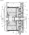
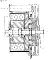
- the figures 2 and 4 to 8 illustrate an embodiment of the powertrain according to the invention.
- the power train with the exception of the second engine, is located inside the bottom bracket 1, which is then closed by two flanges 2 and 3 also serving as a support for the traction motor 4.
- the first motor 5 comprises a stator 20 mounted coaxially with a rotor 19.
- the wound stator 20 is fixed in bottom bracket.
- the first motor is connected to a sun gear 13, which is part of an epicyclic gear train 24.
- the epicyclic gear train is composed of three independent parts, namely the sun gear 13, the planet carrier 14 and the crown 12.
- the sun gear preferably being integrally mounted to the rotor 19 of the first motor 5.
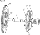
- the epicyclic gear train also comprises a first set of small satellites and a second set of large satellites, as best illustrated in FIG. figure 5 .
- each set of satellites has three gears, as this allows a good balance between the moving parts and the weight of the epicyclic gear.
- the small and large satellites of the first and second sets of satellites are each integral with the same satellite axis 17. It should be noted that the small satellites 15 and the large satellites 16 are both integral with the axis 17.
- the small and large satellites of the first and second sets of satellites are mounted on either side of a carrier 14, as shown in figures 5 and 8 .
- the sun gear engages with the large satellites 16 to increase the speed of the planet carrier 14.
- the speed of the planet carrier 14 is a linear relationship between the speeds of the crown 12 and the sun gear 13.
- the exit plate 23 is mounted on the planet carrier 14.
- the output tray for mounting a chain or a toothed belt 21, which serves to drive in turn the pinion of the rear wheel of the bicycle.
- the small satellites of the first set 15 are engrained with first teeth 12 'provided inside the ring 12, itself part of the epicyclic train.
- Second teeth 12 "of the crown engrain with the second motor 4, which is for this purpose provided with a driving pinion 7.
- the transmission between the driving pinion 7 and the ring is sealed with the closing cap 6.
- the crank axle is preferably secured to the ring gear 12 of the epicyclic gear train, for example by means of splines not shown in the drawing, of course other rotational locking systems may be provided for securing the gear. pedal axle and the crown.
- a crank axle 11 passes through the epicyclic gear train and is supported by bearings 9 as illustrated in FIG. figure 6 .
- the ring 12 drives the small satellites 15, thus rotating the planet carrier 14 secured to the output plate 18.
- This output tray causes the chain or the toothed belt 21.
- a thin sealing wall 10 separates the train epicyclic drive motor 5.
- the control unit is preferably housed in a housing 50 placed near the motors in order to limit the wiring of electrical wires. This housing is preferably circular in shape to match that of the bottom bracket housing.
- the traction motor 4 assists the cyclist by driving the axle of the pedal 11 via two formed gears by the driving pinion 7 and the ring 12.
- the pinion 7 of the second motor 4 is geared on the teeth 12 "of the ring, the rotation of the pinion driven by the second motor will drive the ring in rotation.
- the pinion 7 can be engaged with a receiving wheel, which is mounted on the axis of the crankset. The combination of the torque provided by the second motor 4 and the human force rotates the crown 12 This arrangement is even more interesting if the second engine 4 benefits, like the cyclist, from a gearshift (of the variable transmission), thereby working at a better efficiency.
- the powertrain according to the invention can operate either with several gear ratios, with only one gear ratio.
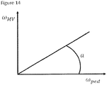
- the transmission ratio depends in fact on the ratio of the speed of the drive motor 5 and that of the pedal 27. This ratio is equivalent to the angular coefficient of the line representing the evolution of the speed of the MV as a function of the speed of the pedal, as it will be described in more detail below. It is therefore possible to remain on a constant transmission ratio while keeping this constant angular coefficient. To change gear, the cyclist changes the value of this angular coefficient.
- the drive motor is controlled in angular speed to fulfill its function of speed variator.
- the rotor 19 of the first motor is mounted on a freewheel 18, itself mounted on the frame 29 to prevent the first drive motor from rotating in the opposite direction (opposite to the predetermined direction of rotation of the pedal).
- the function of this freewheel is to allow a power transmission purely mechanical to the wheel operating in case of break with any kind of motor power supply. In case of engine failure, the cyclist can still pedal to return home.
- This mode of operation corresponds to the smallest transmission ratio. During this mode the first drive motor is not powered and the second traction motor can be powered to assist the cyclist.
- the traction motor 4 assists the cyclist's movement by adding torque to the pedal. During certain cases of operation, this engine can also slow down the cyclist's pedaling movement. Its role is to constantly monitor the level of assistance that the control unit requires, regardless of the transmission ratio "engaged" and regardless of the speed of travel. This engine is driven in torque.
- the bike on which the power train is mounted can also be equipped with a traditional freewheel in the rear wheel pinion preventing the chain (or belt) to turn when the bike continues to roll through its inertia.
- a traditional freewheel in the rear wheel pinion preventing the chain (or belt) to turn when the bike continues to roll through its inertia.
- Another version (detailed below) would use a pinion attached to the wheel without intermediate freewheel thus allowing to brake on the drive motor and thus recharge the drive motor.
- the torque to be supplied by the first motor 5 to the carrier is imposed by the law of the road. It is speed-controlled to follow a transmission ratio setpoint.
- the speed of the second motor is imposed by the pedaling rate of the cyclist because kinematically connected by gears or other transmission system to the crown. This one will be piloted in couple in order to assist the cyclist in his effort.
- the speed reference is a linear function of the pedaling speed, the multiplying coefficient depends on the speed ratio chosen by the cyclist or determined by the control unit according to the speed at which the cyclist is driving.
- the control unit has an input for receiving a report signal of speed indicating a gear ratio selected by the cyclist from a predetermined number of gear ratios.
- the powertrain comprises a third sensor connected to the control unit and arranged to measure the speed at which the bicycle is propelled by a cyclist.
- the control unit is then arranged to produce on the basis of the measured speed a speed ratio signal indicating a selected speed ratio from a predetermined number of gear ratios.
- Another advantage of the present powertrain is its ability to operate as a brake and thus recover the braking energy to recharge the battery if the freewheel originally installed on the rear wheel sprocket is omitted.
- the chain turns and drives the powertrain output tray.
- the carrier is now acting as a power differential. It will tend to turn the drive motor (in its normal direction) which will be controlled at this time as a generator to brake the bike and transmit power to the battery.
- This system could for example be activated by a coaster, such as the roadster system.
- the power of the brake and therefore the amount of energy supplied to the battery could be controlled according to the back-pedaling force that the cyclist exerts.
- the first motor 5 On the smallest gear, the first motor 5 is not powered. Only the second engine participates in electric assistance. The sun gear is blocked by the free wheel 18 linking the frame (left flange (2)) to the rotor 19 of the first motor 5. To increase the transmission ratio, it is necessary to start the first motor 5. This then begins to participate in the global electrical assistance. At most we increase the speed of the first engine 5, the more we will increase the transmission ratio and the more it will participate in the overall assistance.
- the figure 9 schematically illustrates the electrical connection of the motors 4 and 5 and the control unit 38.
- each motor is equipped with a Hall effect sensor 35, 36 can include up to six counts per rotor revolution.
- the information from these sensors is sent to the control unit for analysis.
- the control unit also calculates the current injected into each motor in order to calculate the torque on each motor (torque proportional to the intensity of the electric current).
- a speed sensor 37 at the wheel is required at the control unit, if different gear ratios are available.
- the control unit performs a calculation using the torque on the shaft of the two motors. This is easily measurable, since the torque is proportional to the current flowing in the induction coils of the direct current motor.
- the control unit can calculate the speed of the bicycle from the engine speeds, for example with the kinematic equations of the epicyclic gear train.
- the speed of the wheel is decoupled from the speed of the output tray and this speed sensor 37 is necessary.
- notation Designation Unit ⁇ flat angular speed of the output tray [Rad / s] ⁇ MV angular speed of the sun gear of the first motor [Rad / s] ⁇ MT angular velocity of the second motor [Rad / s] ⁇ ped angular velocity of the pedals [Rad / s] ⁇ R angular speed of the bicycle rear wheel [Rad / s] ⁇ pAR angular speed of the rear sprocket [Rad / s] C x couple on the element x [Nm] P x power on the element x [W] R reduction ratio of an epicyclic gear [Su] * R trans transmission reduction ratio [Su] * R second engine reduction ratio of the second
- the speed of rotation ⁇ MV of the first engine will be, according to the gear ratio engaged (electronic handlebar breeder or all-automatic mode), equal to a coefficient a multiplied by the speed of rotation ⁇ ped pedaling.
- a request for a gear change from the cyclist or the automatic controller will therefore have the effect of changing this coefficient a.
- the first motor 5 will therefore be regulated in speed by a regulation loop using the information of a sensor measuring the angular velocity of the pedal axle. This operation is validated by the definition of the gear ratio (simplified term meaning the gear ratio of the bike). Indeed, keeping a coefficient "a" constant, the gear ratio also remains constant. By increasing the coefficient "a", the multiplication increases.
- the level of assistance defines as the ratio of the electric power supplied to the total power supplied to the output tray.
- the level of assistance increases well with the rotational speed of the first engine. This means that on low gear ratios, the level of assistance will be low and for high gear ratios, the level of assistance will be at a maximum.
- the powertrain according to the invention also comprises the second motor 4.
- the second so-called traction motor has several interesting roles. Its first role is obviously to obtain a degree of freedom in the control of this powertrain in order to adapt the level of assistance to any situation.
- the second motor is directly connected, via a reduction gear set, to the crank axle so that it is now possible to increase the level of assistance on the low gear ratios.
- the arrangement of this second engine 4 in the kinematic chain is interesting because this engine enjoys, like the cyclist, the gear ratio, allowing a large torque during driving situations requiring a lot of effort as a large coast or rolling on a deformable soil.
- NivAssist at + R MT VS MT VS MV at + R
- the second engine will therefore be controlled in a closed loop with a torque setpoint allowing the right level of assistance, its rotation speed being imposed by the pedaling speed via the reduction ratio dictated by the geometry of its transmission.
- ⁇ MT R MT .
- ⁇ ped R MT .
- this motor can also work in brake mode, allowing in all cases a total control of the level of assistance.
- Operation in generator mode, which returns the energy thus created in the drive motor, is also considered in pure pedal mode (no current from the battery) for driving at a speed greater than the regulated speed. This way of doing so would replace the addition of a second epicyclic gear needed for this function.
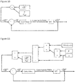
- the figure 10 shows the block diagram of the speed reference of the drive motor.
- the measured angular velocity ⁇ MT of the second motor and the multiplying coefficient divided by the reduction ratio RMT of the second motor are multiplied with each other to form the angular velocity deMV at the first motor.
- the control unit 38 is mounted in a control loop to ensure that the first motor is actually powered to rotate at the target angular speed.
- the angular coefficient of the straight line "speed of the first motor - pedaling speed" is constant.
- the control unit therefore imposes on the drive motor a speed proportional to the speed pedaling on the same gear. To vary the transmission ratio, simply change the value of this angular coefficient noted "a".
- the figure 11 illustrates the calculation block diagram of the torque setpoint to be imposed on the traction motor 4. This is a function of the resistive torque present on the rotor of the first motor 5.
- the torque setpoint of the second motor will also depend on the level of assistance to impose on the cyclist.
- the reduction ratio of the epicyclic gear train R and assistance level multiplier coefficient a are added to then be multiplied with the determined assistance level.
- the torque setpoint CMT for the second motor is then determined from this determined assistance level and the measured torque of the first motor.
- a regulation loop is also provided to ensure that the second motor provides the torque determined by the torque of the setpoint.
- the figure 12 shows with the help of a flowchart the management performed by the control unit.
- the powertrain When the powertrain is energized, the angular velocity of the second motor is measured. If it is greater than zero, the set speed of the first motor and the set torque of the second motor are determined. Preferably it is also checked whether the brake sensor is activated before providing the instructions to the engines.
- the powertrain is operated at high speed as long as the first engine is running.
- some countries prohibit electrical assistance above a certain limit (25 km / h in Europe, 32 km / h in Canada). This would mean that the drive motor should be de-energized once the speed limit is reached, thus shifting from a high gear to the lowest gear, thus putting the rider in an uncomfortable position if he wants to cross this speed.
- the first solution has the advantage of being the simplest and least expensive, but may scare away future buyers of this type of technology, although a speed greater than 25 km / h is rarely used on an electric bike .
- the figure 13 illustrates the operation with option (2a) of the additional epicyclic gear train.
- the epicyclic train TE2 is inserted on the same side as the TE1.
- the crown of the TE1 (the pedal) is in fact linked to the carrier of the TE2 and the carrier of the TE1 (the plateau) is connected to the sun gear of the TE2.
- the crown of the TE2 turns in a vacuum.
- an actuator locks the crown of the TE2
- the sun gear of TE1 this time turns faster than the first engine, which is at a standstill (freewheel between the two) and the pedal alone the output tray via a fixed speed ratio dependent on the internal ratio of TE2.
- a cogged gear is provided. Compared to the basic mechanism, an axle and toothed wheels were added at the top.
- the shaft is fixed via bearings in the power train frame.
- the toothed wheel 3a is integral with the axis and is driven by the crown of the TE1 (pedal).
- Wheel No. 2 rotates with the axis but is free in axial translation.
- Wheel No. 1 is mounted on a bearing (or needle cage) and is thus detached from its axis in "assisted" mode.
- the power from the second engine is transmitted to the pedal through the wheel n ° 2 with helical teeth.
- the axial thrust provided by the helical gear keeps wheel # 2 away from # 1.
- the powertrain can also operate with a short-circuit axis. Once engaged, the axis equipped with these two gears actually short circuit pedal and the output tray. It is the gear ratio that will impose the imposed mechanical speed. This alternative is the simplest of the three. This is probably the least expensive too. The only difficulty is in the clutch. Finally, adding parts tends to increase the cost, weight and bulk of the mechanism.
- the third solution does not require any additional mechanical parts to be added to the basic system illustrated in Figures 4 to 7 .
- the technique is here in power electronics.
- the principle is to use the second traction motor as an electric generator and to reinject the electricity thus produced into the drive motor.
- a variant of this technology would be to use the second engine as a generator, to send the electricity produced in the battery and feed the MV accordingly from the battery.
- the power supply by the battery is indeed better quality (voltage, flow) and the operation of the bike will be better.
- This type of scheme is identical to the idea explained above but with another path used by electricity. It will nevertheless be necessary to check that this type of operation is accepted at the homologation level of the engine.
- Another big advantage of the third solution is that it allows to drive with multiple gear ratios in "pure pedaling mode" even in case of battery failure or full discharge, while the three variants of the second solution only allow the minimum and maximum ratio of the transmission.
- each motor is equipped with its own Hall effect sensor and the angular velocity of each engine thus measured is returned to the control unit.
- the control unit is also arranged to obtain a measurement of the resistive torque by measuring the current flowing in the stator armature.
- the control unit therefore has torque and angular speed information for both engines at any given time and this is a considerable advantage. Indeed, knowing the speed of the sun gear (speed of the first motor) and the crown (speed of the second motor) of the epicyclic gear, the speed of the output plate is calculated by the equations previously discussed and listed below.
- the control unit thus adjusts the torque of the first motor with the control loop.
- the information of the rider's couple is thus recovered by the torque measurements provided by the two engines.
- One last piece of information is needed to control the powertrain, namely that provided by a speed sensor installed on the front wheel or the rear wheel. Indeed, the speed of the rear wheel can be different from the speed of the wheel pinion when the bike is said to "coasting". It is then necessary to know the exact speed of the bike to know if the assistance can be engaged or not.
- the main role of the first engine is to offer the desired transmission ratio, as previously described.
- the first motor is thus regulated in order to follow a speed setpoint.
- This setpoint is in fact the coefficient "a" divided by the reduction ratio of the second motor and then multiplied by the speed measurement of the Hall effect sensor fitted to the second motor.
- the second traction motor will provide the missing power to maintain the desired level of NivAssist assistance.
- This engine will therefore act especially on low gear ratios (the first engine giving little power to the wheel for this operation) and its power will diminish as the multiplier "a" increases.
- the speed multiplier "a” is either chosen by the cyclist or calculated by the automatic shifting algorithm.
- the R & R SECOND MOTOR are fixed dimensional values specific to the gears.
- C MV can be measured by the control unit (intensity measurement). In order to have the required level of assistance, it is therefore sufficient to control the torque of the second motor.
- the control unit will therefore have to integrate a control loop ( figure 11 ) regulating the torque of the second motor.
- the torque setpoint of the first motor can be either positive or negative. In the case where it is negative, the first motor will operate in generator mode and thus charge the battery.
- the change of speed ratio is done by controlling the multiplier coefficient "a".
- the minimum value of a is the zero value, which corresponds to the first mechanical speed ratio when the free wheel connecting the sun gear to the bottom bracket is blocked.
- the powertrain would be equipped with a small electronic box consisting of two buttons electronic, attached to the handlebars of the bike, and returning the information to the control unit via electrical wires (or possibly wireless technology).
- One of the two buttons is used to increase speed and the other to go down.
- the motorization system therefore acts as a sequential electronic box.
- a number of discrete reports, each corresponding to a coefficient value a, will therefore be implemented in the computer managing the motorization. Pressing the "+” button moves the control unit from “a” to the next higher one. By pressing "-”, the control unit changes to a lower value of "a”. This operation is illustrated by the example taken from figure 15 .
- the engine incorporates five discreet reports.
- the index M means that the ratio is "mechanical" and the index E means that the ratio is electric.
- the advantage of this manual version is to offer the rider the ability to adapt these ratios as he wishes as a derailleur bike while offering a high quality gearshift. Indeed, with this system, speed changes can be done on the fly (double click, triple click), under torque and even when stopped.
- the speed control is here electronic and not mechanical, which offers an increased ease of support on the controls and offers great robustness to the system. There is no adjustment to (re) make, nor wear, nor risk of failure (breakage of the wire rope). In summary, there is a huge gain in comfort of use of speeds.
- the ways of controlling the first drive motor 5 and the second traction motor 4 in normal mode will now be described.
- the figure 18 illustrates the assistance provided according to the terrain on which the cyclist is traveling. Takeoff means putting the bike in motion from the stop. The assistance is triggered as soon as the speed of the pedal reaches a certain threshold. At this moment, the information of the couple on the pedals is available via the above formula.
- the control unit is therefore arranged to calculate the torque setpoint to be applied to the second motor and the second motor is thus started. On the lowest gear, the first engine is off, on all other gears it is running. Both engines are now regulated as explained previously.
- the control unit In order for the assistance to be reactive, it is preferable for the control unit to receive the speed information of the first motor with a low response time. For this, it is preferable that the resolution of the angular sensor is fine. There should be no problem about this because the pedal and the second motor are separated from a gear with a ratio close to 20, which means that the second engine will have made a turn when the pedal will have only one twentieth of a turn. If there are three changes of state of the Hall effect sensor per revolution of the second motor, it gives us a resolution of 6 degrees on the pedal which should be enough.
- the solution is to change the free wheel for blocking the sun gear when the first motor is off.
- This free wheel would be free to rotate (1 or 2 degrees) in the frame of the bottom bracket and a switch with spring would be inserted in this game.
- the planetary will tend to want to turn in the opposite direction of the march and will press against the switch, which will start the operation of the first engine and the second engine.
- the shifting is manual or automatic, as soon as the coefficient "a" changes, the setpoint of the first engine is changed and the first engine changes its speed. It is possible for the manual mode to impose acceleration / deceleration ramps to obtain a linear and smooth shifting. Like most power-assisted bikes, the powertrain comes with switches in the brake handles. As soon as the control unit receives the braking information, it switches off both electric motors.
- the second motor When the measured cyclist's torque falls below a certain threshold, the second motor is de-energized.
- the first engine reduces its speed because it is related to the speed of pedaling via the coefficient multiplier "a". If the cyclist pedal backwards, operating the freewheel of the rear sprocket of the bicycle, the first motor is de-energized.
- the recovery is done just like start-up because all parts of the epicyclic train are stopped before the cyclist begins to put effort on his pedals.
- the belt (or chain) does not rotate due to the freewheel placed in the rear sprocket (as for a conventional bike).
- the first engine starts (if speed ratio different from the smaller one) by following the speed setpoint imposed by the speed gear engaged.
- the control loop of the second motor is also reactivated.
- Pure pedaling can be practiced in situations where the battery is discharged or broken down. In this case the cyclist puts his bike in motion by simply pedaling. His bike will first be on the first gear ratio (free wheel of the sun gear locked against the frame). The following reports are either changed manually or automatically. The energy required to supply the first motor for which it follows its speed setpoint will be taken by the second engine thus operating in generator mode. Its brake torque being controlled by the phasing of the switching of the control.
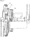
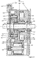
- the figure 19 illustrates another embodiment of the powertrain according to the invention.
- all the components of the powertrain is located inside a closed housing 101 and independent of the bicycle frame.
- the housing 101 consists of three assembled parts, namely the right housing 102 ', the left housing 102 "and the cover 103.
- the housing 101 is fixed to the frame of the bicycle with fasteners, for example formed by screws
- the case 101 contains the axle of the pedal 111 at its center, the two electric motors 104 and 105 as well as the electronic control circuit 106. If necessary, the frame of the bicycle will be adapted or designed to fix the case.
- the first motor 105 includes a stator 120 mounted coaxially with a rotor 119.
- the wound stator 120 is attached to the right housing 102 '.
- the first motor is connected to a sun gear 113, forming part of an epicyclic gear train 124.
- the epicyclic gear train is composed of three independent parts, namely the sun gear 113, the planet carrier 114 and the ring gear 112.
- the sun gear is preferably mounted in solidarity with the rotor 119 of the first motor 105.
- the epicyclic gear also comprises a set of 115 double satellites. Each double 115 satellite consists of two toothed wheels, integral with each other and preferably of different sizes.
- the smallest gear wheel is called “small satellite” 116 'and the largest gear wheel is called “large satellite” 116.
- Each double satellite 115 is mounted on a satellite axis 117 via one or two bearing (s).
- the satellite axis 117 is preferably fixed at both ends to the planet carrier 114 on one side and to the reinforcing plate of the planet carrier 114 'on the other side.
- the sun gear meshes with the large satellites 116 "to increase the speed of rotation of the planet carrier 114.
- the speed of rotation of the planet carrier 114 is a linear relationship of the rotational speeds of the ring gear 112 and the sun gear. 113.
- the output tray 123 is integral with the carrier 114.
- a hollow output shaft 123 ' mounted coaxially around the bottom bracket axis 111, transmits the torque from the carrier 114, located on the left-hand side
- the output tray 123 is used to mount a chain or timing belt therein, which in turn drives the pinion of the rear wheel of the bicycle.
- the rotor 119 of the first motor 105 is guided by one or two bearings (s) housed in the right housing 102 '.
- a crank axle 111 passing through the epicyclic train and the output shaft is supported by two bearings.
- the bearing On the right, the bearing is connected to the output axis 123 '.
- the bearing On the left, the bearing is housed in the housing 101.
- the output shaft 123 'and the carrier 114 are assembled to form a rigid assembly guided by two bearings.
- the bearing is housed in the housing 101.
- it is a bearing equipped with a freewheel 118 and connected to the bottom bracket axis 111, preventing the planet carrier 114 from rotating more slowly that the bottom bracket shaft 111.
- the freewheel 118 forces the rotor 119 the first motor 105 to rotate at the same speed as the axis of the pedal if this first motor is not powered.
- the two inputs of the epicyclic gear rotating at the same speed rotate the output tray at this same speed (by virtue of the kinematic equations of an epicyclic train).
- This arrangement allows to keep a torque transmission in case the first motor 105 is overloaded or in case of failure of the control system.
Priority Applications (1)
| Application Number | Priority Date | Filing Date | Title |
|---|---|---|---|
| EP17202988.6A EP3323705B1 (fr) | 2012-04-27 | 2013-04-26 | Groupe motopropulseur |
Applications Claiming Priority (2)
| Application Number | Priority Date | Filing Date | Title |
|---|---|---|---|
| BE201200284A BE1020653A4 (fr) | 2012-04-27 | 2012-04-27 | Groupe motopropulseur. |
| PCT/EP2013/058816 WO2013160477A1 (fr) | 2012-04-27 | 2013-04-26 | Groupe motorpropulseur pour vehicule a pedales |
Related Child Applications (1)
| Application Number | Title | Priority Date | Filing Date |
|---|---|---|---|
| EP17202988.6A Division EP3323705B1 (fr) | 2012-04-27 | 2013-04-26 | Groupe motopropulseur |
Publications (2)
| Publication Number | Publication Date |
|---|---|
| EP2841328A1 EP2841328A1 (fr) | 2015-03-04 |
| EP2841328B1 true EP2841328B1 (fr) | 2017-12-06 |
Family
ID=46798907
Family Applications (2)
| Application Number | Title | Priority Date | Filing Date |
|---|---|---|---|
| EP13726434.7A Active EP2841328B1 (fr) | 2012-04-27 | 2013-04-26 | Groupe motorpropulseur pour vehicule a pedales |
| EP17202988.6A Active EP3323705B1 (fr) | 2012-04-27 | 2013-04-26 | Groupe motopropulseur |
Family Applications After (1)
| Application Number | Title | Priority Date | Filing Date |
|---|---|---|---|
| EP17202988.6A Active EP3323705B1 (fr) | 2012-04-27 | 2013-04-26 | Groupe motopropulseur |
Country Status (9)
| Country | Link |
|---|---|
| US (1) | US9254890B2 (ja) |
| EP (2) | EP2841328B1 (ja) |
| JP (1) | JP6118398B2 (ja) |
| CN (1) | CN104520179B (ja) |
| BE (1) | BE1020653A4 (ja) |
| ES (1) | ES2964748T3 (ja) |
| PL (1) | PL3323705T3 (ja) |
| TW (1) | TWI589486B (ja) |
| WO (1) | WO2013160477A1 (ja) |
Cited By (2)
| Publication number | Priority date | Publication date | Assignee | Title |
|---|---|---|---|---|
| EP3790789B1 (de) | 2018-03-06 | 2021-10-06 | Brose Antriebstechnik GmbH & Co. Kommanditgesellschaft, Berlin | Antriebssystem |
| WO2022017859A1 (de) | 2020-07-24 | 2022-01-27 | Robert Bosch Gmbh | Verfahren zur steuerung einer antriebsvorrichtung eines fahrrads, antriebsvorrichtung für ein fahrrad und fahrrad |
Families Citing this family (51)
| Publication number | Priority date | Publication date | Assignee | Title |
|---|---|---|---|---|
| US10207772B2 (en) * | 2011-01-28 | 2019-02-19 | Paha Designs, Llc | Gear transmission and derailleur system |
| KR101489933B1 (ko) * | 2013-08-12 | 2015-02-04 | 주식회사 하이코어 | 입력 합성 기어 시스템 |
| DE102013206713A1 (de) * | 2013-04-15 | 2014-10-16 | Robert Bosch Gmbh | Motorisch und mit Muskelkraft betreibbares Fahrzeug |
| JP5523636B1 (ja) * | 2013-07-16 | 2014-06-18 | パナソニック株式会社 | 電動アシスト自転車 |
| KR101531624B1 (ko) * | 2013-11-15 | 2015-07-06 | 주식회사 만도 | 전기 자전거 및 그 제어방법 |
| BE1022240B1 (fr) * | 2014-09-02 | 2016-03-04 | E2 Drives Sa | Groupe motopropulseur pour un vehicule a pedales |
| JP2017533141A (ja) * | 2014-10-31 | 2017-11-09 | ピアッジオ・エ・チ・ソチエタ・ペル・アツィオーニ | 電動ペダルアシスト自転車用の推進装置およびそれを用いたペダルアシスト自転車 |
| JP6325430B2 (ja) * | 2014-12-17 | 2018-05-16 | 株式会社シマノ | 自転車用ドライブユニット |
| US9469373B2 (en) * | 2014-12-17 | 2016-10-18 | VeloMetro Mobility Inc. | Drivetrain system for an electrically assisted human powered vehicle |
| JP2016165911A (ja) * | 2015-03-09 | 2016-09-15 | パナソニックIpマネジメント株式会社 | 電動自転車 |
| JP6538393B2 (ja) * | 2015-03-25 | 2019-07-03 | 株式会社シマノ | 自転車の変速装置 |
| CN106143772B (zh) * | 2015-03-26 | 2019-04-09 | 久鼎金属实业股份有限公司 | 配合行星齿轮组的自行车无段变速速比控制方法 |
| US9803750B2 (en) * | 2015-05-01 | 2017-10-31 | GM Global Technology Operations LLC | Electric bike powertrain with compound planetary |
| GB2540962A (en) * | 2015-07-31 | 2017-02-08 | Nexxt E-Drive Ltd | A Method of operating a pedal cycle having an electro-mechanical drive arrangement |
| WO2017079709A2 (en) * | 2015-11-08 | 2017-05-11 | Fabian Lis | An energy harvesting power-assist system and method for light vehicles |
| JP2017088092A (ja) | 2015-11-16 | 2017-05-25 | 株式会社シマノ | 自転車用ドライブユニット |
| JP2017088134A (ja) * | 2015-11-17 | 2017-05-25 | 株式会社シマノ | 自転車用ドライブユニット |
| JP2017114449A (ja) | 2015-12-25 | 2017-06-29 | 株式会社シマノ | 自転車用ドライブユニット、および、その制御装置 |
| JP2017132440A (ja) * | 2016-01-29 | 2017-08-03 | 株式会社シマノ | 自転車用駆動装置 |
| JP2017132439A (ja) * | 2016-01-29 | 2017-08-03 | 株式会社シマノ | 自転車用駆動装置 |
| EP3452363B1 (en) * | 2016-05-04 | 2022-01-05 | Farthing Technology Pty Ltd | A pedal cycle drivetrain and a human powered vehicle |
| US10167049B2 (en) * | 2016-09-13 | 2019-01-01 | National Cheng Kung University | Crank treading torque detection device for electric bicycle |
| EP3558805A1 (en) | 2016-12-23 | 2019-10-30 | intuEdrive BV | Hybrid powertrain for a pedal vehicle and control unit therefor |
| DE102017003945B4 (de) * | 2017-04-24 | 2022-01-13 | Oechsler Ag | Elektromotorischer Fahrradzusatzantrieb mit stufenlos variabler Übersetzung |
| JP6916047B2 (ja) * | 2017-06-16 | 2021-08-11 | 株式会社シマノ | 自転車用制御装置 |
| DE102017212347A1 (de) | 2017-07-19 | 2019-01-24 | Robert Bosch Gmbh | Tretlagerantrieb eines Fahrrads |
| BE1025518B1 (fr) * | 2017-08-30 | 2019-04-03 | E2 Drives Sa | Groupe motopropulseur |
| CN107685828B (zh) * | 2017-09-19 | 2023-03-24 | 八方电气(苏州)股份有限公司 | 电动自行车无级变速传动装置 |
| DE102017219398A1 (de) | 2017-10-27 | 2019-05-02 | Brose Antriebstechnik GmbH & Co. Kommanditgesellschaft, Berlin | Hybridantrieb für ein Elektrofahrrad |
| CN108163126A (zh) * | 2018-01-03 | 2018-06-15 | 长安大学 | 一种差动轮系合成助力自行车 |
| BE1026017B1 (fr) | 2018-02-16 | 2019-09-16 | E2 Drives Sa | Groupe motopropulseur |
| CN111801270B (zh) * | 2018-03-05 | 2022-05-24 | 本田技研工业株式会社 | 自行车运动量测量装置和自行车 |
| JP7131940B2 (ja) * | 2018-03-29 | 2022-09-06 | 株式会社シマノ | 人力駆動車用制御装置 |
| EP3587235A1 (en) | 2018-06-28 | 2020-01-01 | intuEdrive BV | Method for providing electrical propulsion assistance in a pedal-propelled vehicle, and controller implementing same |
| DE102018217883B4 (de) * | 2018-09-25 | 2020-06-04 | Zf Friedrichshafen Ag | Antriebsanordnung für ein Fahrrad oder Pedelec |
| DE102018217093A1 (de) * | 2018-10-05 | 2020-04-09 | Zf Friedrichshafen Ag | Antriebsanordnung für ein Pedelec |
| NL2021891B1 (en) * | 2018-10-26 | 2020-05-13 | Advancing Tech B V | Transmission system |
| CN109756068A (zh) * | 2018-12-11 | 2019-05-14 | 浙江亚特电器有限公司 | 一种包含开关磁阻电机的割草机 |
| DE102019201811B3 (de) * | 2019-02-12 | 2020-03-19 | Brose Antriebstechnik GmbH & Co. Kommanditgesellschaft, Berlin | Antriebsvorrichtung für ein Elektrofahrrad und Elektrofahrrad mit einer Antriebsvorrichtung |
| KR102034744B1 (ko) * | 2019-07-29 | 2019-10-21 | 백성구 | 자전거 구동장치 |
| TWI708454B (zh) * | 2019-07-30 | 2020-10-21 | 上銀科技股份有限公司 | 具備無線供電功能的線性傳動裝置 |
| US11142082B2 (en) | 2019-08-07 | 2021-10-12 | Hiwin Technologies Corp. | Linear transmission device with capability of wireless power supply |
| BE1027127B1 (fr) * | 2019-08-16 | 2020-10-19 | E2 Drives Sa | Système de propulsion pour véhicule à assistance électrique |
| DE202019005932U1 (de) | 2019-09-25 | 2023-06-06 | Karlheinz Nicolai | Fahrrad mit elektrischem Hilfsantrieb |
| DE102019006708B4 (de) * | 2019-09-25 | 2023-04-13 | Karlheinz Nicolai | Fahrrad mit elektrischem Hilfsantrieb |
| CN111532369A (zh) * | 2020-06-03 | 2020-08-14 | 深圳市洋利昂科技有限责任公司 | 一种驱动与变速一体式中置装置及电助力自行车 |
| US11300184B1 (en) * | 2020-11-16 | 2022-04-12 | Trinity Innovative Solutions, Llc | Variable output transmission |
| DE102021000585B4 (de) | 2021-02-05 | 2024-04-18 | EGS Entwicklungsgesellschaft für Getriebesysteme mbH | Modulares Antriebssystem |
| TWI768845B (zh) * | 2021-04-23 | 2022-06-21 | 張勛 | 發電裝置 |
| TWI818453B (zh) * | 2022-02-25 | 2023-10-11 | 如陽科技股份有限公司 | 減速機之傳動系統 |
| WO2023170394A1 (en) * | 2022-03-07 | 2023-09-14 | Ebike Systems Ltd | Electrically-assisted pedal cycles |
Citations (1)
| Publication number | Priority date | Publication date | Assignee | Title |
|---|---|---|---|---|
| JP2008285069A (ja) * | 2007-05-18 | 2008-11-27 | Bridgestone Corp | 駆動力制御装置及び電動アシスト自転車 |
Family Cites Families (13)
| Publication number | Priority date | Publication date | Assignee | Title |
|---|---|---|---|---|
| CA2259771C (en) * | 1998-02-19 | 2003-04-01 | Hitachi, Ltd. | Transmission, and vehicle and bicycle using the same |
| US6296072B1 (en) * | 1999-01-20 | 2001-10-02 | Opti-Bike Llc | Electric bicycle and methods |
| JP2001106165A (ja) * | 1999-10-13 | 2001-04-17 | Honda Motor Co Ltd | 電動補助ユニット |
| EP1298051A3 (en) * | 2001-09-28 | 2005-12-14 | Kabushiki Kaisha Moric | Electrically assisted unit |
| CN100406343C (zh) * | 2004-09-27 | 2008-07-30 | 捷安特(中国)有限公司 | 电动自行车中置驱动同轴式动力组 |
| JP2008137517A (ja) * | 2006-12-01 | 2008-06-19 | Bridgestone Corp | 電動アシスト自転車用駆動装置、及び電動アシスト自転車 |
| GB0902356D0 (en) * | 2009-02-12 | 2009-04-01 | Nexxtdrive Ltd | Bicycle transmission systems |
| CN101792006B (zh) * | 2010-03-10 | 2013-01-23 | 西南大学 | 轮毂式手自一体智能化自适应传动传感电驱动自动变速器 |
| JP5728269B2 (ja) * | 2011-03-31 | 2015-06-03 | 本田技研工業株式会社 | 電動アシスト自転車 |
| DE102012104150A1 (de) * | 2012-05-11 | 2013-11-14 | Rolf Strothmann | Fahrzeug, insbesondere Fahrrad, mit elektrischem Hilfsantrieb |
| JP6218172B2 (ja) * | 2012-12-17 | 2017-10-25 | ヤマハ発動機株式会社 | 駆動ユニット及び電動補助自転車 |
| JP6005110B2 (ja) * | 2013-10-29 | 2016-10-12 | 株式会社シマノ | 自転車用制御装置 |
| JP2015098227A (ja) * | 2013-11-18 | 2015-05-28 | ヤマハ発動機株式会社 | 電動補助車両 |
-
2012
- 2012-04-27 BE BE201200284A patent/BE1020653A4/fr active
-
2013
- 2013-04-26 US US14/397,460 patent/US9254890B2/en active Active
- 2013-04-26 CN CN201380022419.0A patent/CN104520179B/zh active Active
- 2013-04-26 WO PCT/EP2013/058816 patent/WO2013160477A1/fr active Application Filing
- 2013-04-26 PL PL17202988.6T patent/PL3323705T3/pl unknown
- 2013-04-26 JP JP2015507559A patent/JP6118398B2/ja active Active
- 2013-04-26 EP EP13726434.7A patent/EP2841328B1/fr active Active
- 2013-04-26 EP EP17202988.6A patent/EP3323705B1/fr active Active
- 2013-04-26 ES ES17202988T patent/ES2964748T3/es active Active
- 2013-04-26 TW TW102115045A patent/TWI589486B/zh active
Patent Citations (1)
| Publication number | Priority date | Publication date | Assignee | Title |
|---|---|---|---|---|
| JP2008285069A (ja) * | 2007-05-18 | 2008-11-27 | Bridgestone Corp | 駆動力制御装置及び電動アシスト自転車 |
Cited By (3)
| Publication number | Priority date | Publication date | Assignee | Title |
|---|---|---|---|---|
| EP3790789B1 (de) | 2018-03-06 | 2021-10-06 | Brose Antriebstechnik GmbH & Co. Kommanditgesellschaft, Berlin | Antriebssystem |
| WO2022017859A1 (de) | 2020-07-24 | 2022-01-27 | Robert Bosch Gmbh | Verfahren zur steuerung einer antriebsvorrichtung eines fahrrads, antriebsvorrichtung für ein fahrrad und fahrrad |
| DE102020209373A1 (de) | 2020-07-24 | 2022-01-27 | Robert Bosch Gesellschaft mit beschränkter Haftung | Verfahren zur Steuerung einer Antriebsvorrichtung eines Fahrrads, Antriebsvorrichtung für ein Fahrrad und Fahrrad |
Also Published As
| Publication number | Publication date |
|---|---|
| TWI589486B (zh) | 2017-07-01 |
| BE1020653A4 (fr) | 2014-02-04 |
| JP6118398B2 (ja) | 2017-04-19 |
| EP3323705B1 (fr) | 2023-11-08 |
| ES2964748T3 (es) | 2024-04-09 |
| US9254890B2 (en) | 2016-02-09 |
| US20150122565A1 (en) | 2015-05-07 |
| JP2015514635A (ja) | 2015-05-21 |
| CN104520179A (zh) | 2015-04-15 |
| EP2841328A1 (fr) | 2015-03-04 |
| CN104520179B (zh) | 2017-08-22 |
| EP3323705A1 (fr) | 2018-05-23 |
| WO2013160477A1 (fr) | 2013-10-31 |
| PL3323705T3 (pl) | 2024-03-04 |
| TW201404657A (zh) | 2014-02-01 |
| EP3323705C0 (fr) | 2023-11-08 |
Similar Documents
| Publication | Publication Date | Title |
|---|---|---|
| EP2841328B1 (fr) | Groupe motorpropulseur pour vehicule a pedales | |
| EP3676166B1 (fr) | Groupe motopropulseur | |
| BE1026057B1 (fr) | Groupe motopropulseur pour véhicule à pédales | |
| EP2890605A1 (fr) | Procédé de régulation de l'assistance électrique d'un vélo | |
| EP3752415B1 (fr) | Groupe motopropulseur | |
| EP3638577B1 (fr) | Vélo électrique à chaîne de transmission électrique parallèle à celle de pédalage et procédés de fonctionnement associés | |
| EP3826910A1 (fr) | Velo electrique a chaine de transmission electrique parallele a celle de pedalage, comprenant un mat central integrant le moteur, sa batterie et son electronique de commande | |
| EP4192725A1 (fr) | Dispositif de transmission pour vehicule a propulsion humaine | |
| WO2023180643A1 (fr) | Groupe motopropulseur a transmission pilotee pour velo a assistance electrique | |
| FR3116797A1 (fr) | Unité de pilotage pour engin de mobilité et Procédé associé | |
| WO2017072422A1 (fr) | Dispositif d'assistance motorise, notamment au pédalage, et cycle associe | |
| WO2022112504A1 (fr) | Ensemble de transmission pour engin de mobilité, unité de pilotage pour engin de mobilité, boîtier et procédé de pilotage pour engin de mobilité | |
| FR3013311A1 (fr) | Electro bike kit de moteur electrique pour tous types de velos traditionnel et vtt | |
| FR3111112A1 (fr) | Système de transmission à assistance motorisée pour vélo et vélo équipé dudit système | |
| FR3116796A1 (fr) | Procédé de pilotage pour un ensemble de transmission | |
| FR3116802A1 (fr) | Ensemble de transmission pour engin de mobilité | |
| FR2989058A1 (fr) | Dispositif d'assistance au pedalage par compression et detente d'un fluide sous pression, respectant les contraintes reglementaires des bicyclettes et permettant de recuperer l'energie cinetique du vehicule |
Legal Events
| Date | Code | Title | Description |
|---|---|---|---|
| PUAI | Public reference made under article 153(3) epc to a published international application that has entered the european phase |
Free format text: ORIGINAL CODE: 0009012 |
|
| 17P | Request for examination filed |
Effective date: 20141121 |
|
| AK | Designated contracting states |
Kind code of ref document: A1 Designated state(s): AL AT BE BG CH CY CZ DE DK EE ES FI FR GB GR HR HU IE IS IT LI LT LU LV MC MK MT NL NO PL PT RO RS SE SI SK SM TR |
|
| AX | Request for extension of the european patent |
Extension state: BA ME |
|
| RAP1 | Party data changed (applicant data changed or rights of an application transferred) |
Owner name: E2 DRIVES SA |
|
| TPAC | Observations filed by third parties |
Free format text: ORIGINAL CODE: EPIDOSNTIPA |
|
| 17Q | First examination report despatched |
Effective date: 20160223 |
|
| TPAC | Observations filed by third parties |
Free format text: ORIGINAL CODE: EPIDOSNTIPA |
|
| GRAP | Despatch of communication of intention to grant a patent |
Free format text: ORIGINAL CODE: EPIDOSNIGR1 |
|
| STAA | Information on the status of an ep patent application or granted ep patent |
Free format text: STATUS: GRANT OF PATENT IS INTENDED |
|
| TPAC | Observations filed by third parties |
Free format text: ORIGINAL CODE: EPIDOSNTIPA |
|
| INTG | Intention to grant announced |
Effective date: 20170807 |
|
| GRAS | Grant fee paid |
Free format text: ORIGINAL CODE: EPIDOSNIGR3 |
|
| GRAJ | Information related to disapproval of communication of intention to grant by the applicant or resumption of examination proceedings by the epo deleted |
Free format text: ORIGINAL CODE: EPIDOSDIGR1 |
|
| GRAL | Information related to payment of fee for publishing/printing deleted |
Free format text: ORIGINAL CODE: EPIDOSDIGR3 |
|
| STAA | Information on the status of an ep patent application or granted ep patent |
Free format text: STATUS: EXAMINATION IS IN PROGRESS |
|
| GRAR | Information related to intention to grant a patent recorded |
Free format text: ORIGINAL CODE: EPIDOSNIGR71 |
|
| STAA | Information on the status of an ep patent application or granted ep patent |
Free format text: STATUS: GRANT OF PATENT IS INTENDED |
|
| GRAA | (expected) grant |
Free format text: ORIGINAL CODE: 0009210 |
|
| STAA | Information on the status of an ep patent application or granted ep patent |
Free format text: STATUS: THE PATENT HAS BEEN GRANTED |
|
| INTC | Intention to grant announced (deleted) | ||
| INTG | Intention to grant announced |
Effective date: 20171026 |
|
| AK | Designated contracting states |
Kind code of ref document: B1 Designated state(s): AL AT BE BG CH CY CZ DE DK EE ES FI FR GB GR HR HU IE IS IT LI LT LU LV MC MK MT NL NO PL PT RO RS SE SI SK SM TR |
|
| AX | Request for extension of the european patent |
Extension state: BA ME |
|
| REG | Reference to a national code |
Ref country code: GB Ref legal event code: FG4D Free format text: NOT ENGLISH |
|
| REG | Reference to a national code |
Ref country code: AT Ref legal event code: REF Ref document number: 952122 Country of ref document: AT Kind code of ref document: T Effective date: 20171215 Ref country code: CH Ref legal event code: EP |
|
| REG | Reference to a national code |
Ref country code: IE Ref legal event code: FG4D Free format text: LANGUAGE OF EP DOCUMENT: FRENCH |
|
| REG | Reference to a national code |
Ref country code: DE Ref legal event code: R096 Ref document number: 602013030394 Country of ref document: DE |
|
| REG | Reference to a national code |
Ref country code: NL Ref legal event code: FP |
|
| REG | Reference to a national code |
Ref country code: LT Ref legal event code: MG4D |
|
| PG25 | Lapsed in a contracting state [announced via postgrant information from national office to epo] |
Ref country code: NO Free format text: LAPSE BECAUSE OF FAILURE TO SUBMIT A TRANSLATION OF THE DESCRIPTION OR TO PAY THE FEE WITHIN THE PRESCRIBED TIME-LIMIT Effective date: 20180306 Ref country code: ES Free format text: LAPSE BECAUSE OF FAILURE TO SUBMIT A TRANSLATION OF THE DESCRIPTION OR TO PAY THE FEE WITHIN THE PRESCRIBED TIME-LIMIT Effective date: 20171206 Ref country code: LT Free format text: LAPSE BECAUSE OF FAILURE TO SUBMIT A TRANSLATION OF THE DESCRIPTION OR TO PAY THE FEE WITHIN THE PRESCRIBED TIME-LIMIT Effective date: 20171206 Ref country code: SE Free format text: LAPSE BECAUSE OF FAILURE TO SUBMIT A TRANSLATION OF THE DESCRIPTION OR TO PAY THE FEE WITHIN THE PRESCRIBED TIME-LIMIT Effective date: 20171206 Ref country code: FI Free format text: LAPSE BECAUSE OF FAILURE TO SUBMIT A TRANSLATION OF THE DESCRIPTION OR TO PAY THE FEE WITHIN THE PRESCRIBED TIME-LIMIT Effective date: 20171206 |
|
| REG | Reference to a national code |
Ref country code: AT Ref legal event code: MK05 Ref document number: 952122 Country of ref document: AT Kind code of ref document: T Effective date: 20171206 |
|
| PG25 | Lapsed in a contracting state [announced via postgrant information from national office to epo] |
Ref country code: BG Free format text: LAPSE BECAUSE OF FAILURE TO SUBMIT A TRANSLATION OF THE DESCRIPTION OR TO PAY THE FEE WITHIN THE PRESCRIBED TIME-LIMIT Effective date: 20180306 Ref country code: HR Free format text: LAPSE BECAUSE OF FAILURE TO SUBMIT A TRANSLATION OF THE DESCRIPTION OR TO PAY THE FEE WITHIN THE PRESCRIBED TIME-LIMIT Effective date: 20171206 Ref country code: RS Free format text: LAPSE BECAUSE OF FAILURE TO SUBMIT A TRANSLATION OF THE DESCRIPTION OR TO PAY THE FEE WITHIN THE PRESCRIBED TIME-LIMIT Effective date: 20171206 Ref country code: LV Free format text: LAPSE BECAUSE OF FAILURE TO SUBMIT A TRANSLATION OF THE DESCRIPTION OR TO PAY THE FEE WITHIN THE PRESCRIBED TIME-LIMIT Effective date: 20171206 Ref country code: GR Free format text: LAPSE BECAUSE OF FAILURE TO SUBMIT A TRANSLATION OF THE DESCRIPTION OR TO PAY THE FEE WITHIN THE PRESCRIBED TIME-LIMIT Effective date: 20180307 |
|
| PG25 | Lapsed in a contracting state [announced via postgrant information from national office to epo] |
Ref country code: SK Free format text: LAPSE BECAUSE OF FAILURE TO SUBMIT A TRANSLATION OF THE DESCRIPTION OR TO PAY THE FEE WITHIN THE PRESCRIBED TIME-LIMIT Effective date: 20171206 Ref country code: EE Free format text: LAPSE BECAUSE OF FAILURE TO SUBMIT A TRANSLATION OF THE DESCRIPTION OR TO PAY THE FEE WITHIN THE PRESCRIBED TIME-LIMIT Effective date: 20171206 Ref country code: CZ Free format text: LAPSE BECAUSE OF FAILURE TO SUBMIT A TRANSLATION OF THE DESCRIPTION OR TO PAY THE FEE WITHIN THE PRESCRIBED TIME-LIMIT Effective date: 20171206 |
|
| PG25 | Lapsed in a contracting state [announced via postgrant information from national office to epo] |
Ref country code: RO Free format text: LAPSE BECAUSE OF FAILURE TO SUBMIT A TRANSLATION OF THE DESCRIPTION OR TO PAY THE FEE WITHIN THE PRESCRIBED TIME-LIMIT Effective date: 20171206 Ref country code: IT Free format text: LAPSE BECAUSE OF FAILURE TO SUBMIT A TRANSLATION OF THE DESCRIPTION OR TO PAY THE FEE WITHIN THE PRESCRIBED TIME-LIMIT Effective date: 20171206 Ref country code: SM Free format text: LAPSE BECAUSE OF FAILURE TO SUBMIT A TRANSLATION OF THE DESCRIPTION OR TO PAY THE FEE WITHIN THE PRESCRIBED TIME-LIMIT Effective date: 20171206 Ref country code: AT Free format text: LAPSE BECAUSE OF FAILURE TO SUBMIT A TRANSLATION OF THE DESCRIPTION OR TO PAY THE FEE WITHIN THE PRESCRIBED TIME-LIMIT Effective date: 20171206 Ref country code: PL Free format text: LAPSE BECAUSE OF FAILURE TO SUBMIT A TRANSLATION OF THE DESCRIPTION OR TO PAY THE FEE WITHIN THE PRESCRIBED TIME-LIMIT Effective date: 20171206 |
|
| REG | Reference to a national code |
Ref country code: DE Ref legal event code: R026 Ref document number: 602013030394 Country of ref document: DE |
|
| PLBI | Opposition filed |
Free format text: ORIGINAL CODE: 0009260 |
|
| PLAX | Notice of opposition and request to file observation + time limit sent |
Free format text: ORIGINAL CODE: EPIDOSNOBS2 |
|
| PG25 | Lapsed in a contracting state [announced via postgrant information from national office to epo] |
Ref country code: MT Free format text: LAPSE BECAUSE OF FAILURE TO SUBMIT A TRANSLATION OF THE DESCRIPTION OR TO PAY THE FEE WITHIN THE PRESCRIBED TIME-LIMIT Effective date: 20171206 |
|
| 26 | Opposition filed |
Opponent name: LU, YUMING Effective date: 20180906 |
|
| PG25 | Lapsed in a contracting state [announced via postgrant information from national office to epo] |
Ref country code: SI Free format text: LAPSE BECAUSE OF FAILURE TO SUBMIT A TRANSLATION OF THE DESCRIPTION OR TO PAY THE FEE WITHIN THE PRESCRIBED TIME-LIMIT Effective date: 20171206 Ref country code: MC Free format text: LAPSE BECAUSE OF FAILURE TO SUBMIT A TRANSLATION OF THE DESCRIPTION OR TO PAY THE FEE WITHIN THE PRESCRIBED TIME-LIMIT Effective date: 20171206 Ref country code: DK Free format text: LAPSE BECAUSE OF FAILURE TO SUBMIT A TRANSLATION OF THE DESCRIPTION OR TO PAY THE FEE WITHIN THE PRESCRIBED TIME-LIMIT Effective date: 20171206 |
|
| REG | Reference to a national code |
Ref country code: CH Ref legal event code: PL |
|
| GBPC | Gb: european patent ceased through non-payment of renewal fee |
Effective date: 20180426 |
|
| REG | Reference to a national code |
Ref country code: IE Ref legal event code: MM4A |
|
| PG25 | Lapsed in a contracting state [announced via postgrant information from national office to epo] |
Ref country code: LU Free format text: LAPSE BECAUSE OF NON-PAYMENT OF DUE FEES Effective date: 20180426 |
|
| PLBB | Reply of patent proprietor to notice(s) of opposition received |
Free format text: ORIGINAL CODE: EPIDOSNOBS3 |
|
| PG25 | Lapsed in a contracting state [announced via postgrant information from national office to epo] |
Ref country code: LI Free format text: LAPSE BECAUSE OF NON-PAYMENT OF DUE FEES Effective date: 20180430 Ref country code: CH Free format text: LAPSE BECAUSE OF NON-PAYMENT OF DUE FEES Effective date: 20180430 Ref country code: GB Free format text: LAPSE BECAUSE OF NON-PAYMENT OF DUE FEES Effective date: 20180426 |
|
| PG25 | Lapsed in a contracting state [announced via postgrant information from national office to epo] |
Ref country code: FR Free format text: LAPSE BECAUSE OF NON-PAYMENT OF DUE FEES Effective date: 20180430 Ref country code: IE Free format text: LAPSE BECAUSE OF NON-PAYMENT OF DUE FEES Effective date: 20180426 |
|
| RAP2 | Party data changed (patent owner data changed or rights of a patent transferred) |
Owner name: E2 DRIVES SA |
|
| PG25 | Lapsed in a contracting state [announced via postgrant information from national office to epo] |
Ref country code: TR Free format text: LAPSE BECAUSE OF FAILURE TO SUBMIT A TRANSLATION OF THE DESCRIPTION OR TO PAY THE FEE WITHIN THE PRESCRIBED TIME-LIMIT Effective date: 20171206 |
|
| PG25 | Lapsed in a contracting state [announced via postgrant information from national office to epo] |
Ref country code: HU Free format text: LAPSE BECAUSE OF FAILURE TO SUBMIT A TRANSLATION OF THE DESCRIPTION OR TO PAY THE FEE WITHIN THE PRESCRIBED TIME-LIMIT; INVALID AB INITIO Effective date: 20130426 Ref country code: PT Free format text: LAPSE BECAUSE OF FAILURE TO SUBMIT A TRANSLATION OF THE DESCRIPTION OR TO PAY THE FEE WITHIN THE PRESCRIBED TIME-LIMIT Effective date: 20171206 |
|
| REG | Reference to a national code |
Ref country code: DE Ref legal event code: R100 Ref document number: 602013030394 Country of ref document: DE |
|
| PG25 | Lapsed in a contracting state [announced via postgrant information from national office to epo] |
Ref country code: MK Free format text: LAPSE BECAUSE OF NON-PAYMENT OF DUE FEES Effective date: 20171206 Ref country code: CY Free format text: LAPSE BECAUSE OF FAILURE TO SUBMIT A TRANSLATION OF THE DESCRIPTION OR TO PAY THE FEE WITHIN THE PRESCRIBED TIME-LIMIT Effective date: 20171206 |
|
| PLCK | Communication despatched that opposition was rejected |
Free format text: ORIGINAL CODE: EPIDOSNREJ1 |
|
| PG25 | Lapsed in a contracting state [announced via postgrant information from national office to epo] |
Ref country code: AL Free format text: LAPSE BECAUSE OF FAILURE TO SUBMIT A TRANSLATION OF THE DESCRIPTION OR TO PAY THE FEE WITHIN THE PRESCRIBED TIME-LIMIT Effective date: 20171206 Ref country code: IS Free format text: LAPSE BECAUSE OF FAILURE TO SUBMIT A TRANSLATION OF THE DESCRIPTION OR TO PAY THE FEE WITHIN THE PRESCRIBED TIME-LIMIT Effective date: 20180406 |
|
| PLBN | Opposition rejected |
Free format text: ORIGINAL CODE: 0009273 |
|
| STAA | Information on the status of an ep patent application or granted ep patent |
Free format text: STATUS: OPPOSITION REJECTED |
|
| 27O | Opposition rejected |
Effective date: 20200609 |
|
| PGFP | Annual fee paid to national office [announced via postgrant information from national office to epo] |
Ref country code: BE Payment date: 20230315 Year of fee payment: 11 |
|
| P01 | Opt-out of the competence of the unified patent court (upc) registered |
Effective date: 20230523 |
|
| PGFP | Annual fee paid to national office [announced via postgrant information from national office to epo] |
Ref country code: NL Payment date: 20230315 Year of fee payment: 11 |
|
| PGFP | Annual fee paid to national office [announced via postgrant information from national office to epo] |
Ref country code: DE Payment date: 20230427 Year of fee payment: 11 |
|
| PGFP | Annual fee paid to national office [announced via postgrant information from national office to epo] |
Ref country code: NL Payment date: 20240320 Year of fee payment: 12 |