EP2840601A1 - Substrate support pin and substrate support device adopting substrate support pin - Google Patents
Substrate support pin and substrate support device adopting substrate support pin Download PDFInfo
- Publication number
- EP2840601A1 EP2840601A1 EP13734304.2A EP13734304A EP2840601A1 EP 2840601 A1 EP2840601 A1 EP 2840601A1 EP 13734304 A EP13734304 A EP 13734304A EP 2840601 A1 EP2840601 A1 EP 2840601A1
- Authority
- EP
- European Patent Office
- Prior art keywords
- baseplate
- heating device
- supporting pin
- control unit
- pin
- Prior art date
- Legal status (The legal status is an assumption and is not a legal conclusion. Google has not performed a legal analysis and makes no representation as to the accuracy of the status listed.)
- Granted
Links
Images

Classifications
-
- H—ELECTRICITY
- H05—ELECTRIC TECHNIQUES NOT OTHERWISE PROVIDED FOR
- H05B—ELECTRIC HEATING; ELECTRIC LIGHT SOURCES NOT OTHERWISE PROVIDED FOR; CIRCUIT ARRANGEMENTS FOR ELECTRIC LIGHT SOURCES, IN GENERAL
- H05B1/00—Details of electric heating devices
- H05B1/02—Automatic switching arrangements specially adapted to apparatus ; Control of heating devices
- H05B1/0227—Applications
- H05B1/0288—Applications for non specified applications
-
- G—PHYSICS
- G02—OPTICS
- G02F—OPTICAL DEVICES OR ARRANGEMENTS FOR THE CONTROL OF LIGHT BY MODIFICATION OF THE OPTICAL PROPERTIES OF THE MEDIA OF THE ELEMENTS INVOLVED THEREIN; NON-LINEAR OPTICS; FREQUENCY-CHANGING OF LIGHT; OPTICAL LOGIC ELEMENTS; OPTICAL ANALOGUE/DIGITAL CONVERTERS
- G02F1/00—Devices or arrangements for the control of the intensity, colour, phase, polarisation or direction of light arriving from an independent light source, e.g. switching, gating or modulating; Non-linear optics
- G02F1/01—Devices or arrangements for the control of the intensity, colour, phase, polarisation or direction of light arriving from an independent light source, e.g. switching, gating or modulating; Non-linear optics for the control of the intensity, phase, polarisation or colour
- G02F1/13—Devices or arrangements for the control of the intensity, colour, phase, polarisation or direction of light arriving from an independent light source, e.g. switching, gating or modulating; Non-linear optics for the control of the intensity, phase, polarisation or colour based on liquid crystals, e.g. single liquid crystal display cells
-
- H—ELECTRICITY
- H10—SEMICONDUCTOR DEVICES; ELECTRIC SOLID-STATE DEVICES NOT OTHERWISE PROVIDED FOR
- H10P—GENERIC PROCESSES OR APPARATUS FOR THE MANUFACTURE OR TREATMENT OF DEVICES COVERED BY CLASS H10
- H10P72/00—Handling or holding of wafers, substrates or devices during manufacture or treatment thereof
- H10P72/04—Apparatus for manufacture or treatment
- H10P72/0431—Apparatus for thermal treatment
- H10P72/0432—Apparatus for thermal treatment mainly by conduction
-
- H—ELECTRICITY
- H10—SEMICONDUCTOR DEVICES; ELECTRIC SOLID-STATE DEVICES NOT OTHERWISE PROVIDED FOR
- H10P—GENERIC PROCESSES OR APPARATUS FOR THE MANUFACTURE OR TREATMENT OF DEVICES COVERED BY CLASS H10
- H10P72/00—Handling or holding of wafers, substrates or devices during manufacture or treatment thereof
- H10P72/04—Apparatus for manufacture or treatment
- H10P72/0431—Apparatus for thermal treatment
- H10P72/0434—Apparatus for thermal treatment mainly by convection
-
- H—ELECTRICITY
- H10—SEMICONDUCTOR DEVICES; ELECTRIC SOLID-STATE DEVICES NOT OTHERWISE PROVIDED FOR
- H10P—GENERIC PROCESSES OR APPARATUS FOR THE MANUFACTURE OR TREATMENT OF DEVICES COVERED BY CLASS H10
- H10P72/00—Handling or holding of wafers, substrates or devices during manufacture or treatment thereof
- H10P72/70—Handling or holding of wafers, substrates or devices during manufacture or treatment thereof for supporting or gripping
-
- H—ELECTRICITY
- H10—SEMICONDUCTOR DEVICES; ELECTRIC SOLID-STATE DEVICES NOT OTHERWISE PROVIDED FOR
- H10P—GENERIC PROCESSES OR APPARATUS FOR THE MANUFACTURE OR TREATMENT OF DEVICES COVERED BY CLASS H10
- H10P72/00—Handling or holding of wafers, substrates or devices during manufacture or treatment thereof
- H10P72/70—Handling or holding of wafers, substrates or devices during manufacture or treatment thereof for supporting or gripping
- H10P72/76—Handling or holding of wafers, substrates or devices during manufacture or treatment thereof for supporting or gripping using mechanical means, e.g. clamps or pinches
- H10P72/7604—Handling or holding of wafers, substrates or devices during manufacture or treatment thereof for supporting or gripping using mechanical means, e.g. clamps or pinches the wafers being placed on a susceptor, stage or support
- H10P72/7612—Handling or holding of wafers, substrates or devices during manufacture or treatment thereof for supporting or gripping using mechanical means, e.g. clamps or pinches the wafers being placed on a susceptor, stage or support characterised by lifting arrangements, e.g. lift pins
Definitions
- the present invention relates to a baseplate supporting pin as well as a baseplate supporting device using the baseplate supporting pin.
- the production line for the liquid crystal display usually achieves film formation by heating the baseplate.
- the baseplate needs to be placed on the baseplate support member and heated with heating elements interior of the baseplate support member, while before heating, the baseplate needs to be placed on the baseplate supporting pins in advance, and descent to the upper surface of the baseplate support member by ascending and descending of the baseplate supporting pin, and then achieve the heating process.
- the baseplate supporting pin presently used in the production line is made from temperature-uncontrollable solid materials, such that two situations would occur during the actual process of heating the baseplate:
- the first situation is that the baseplate supporting pin contacts with the baseplate when heating the baseplate, and in this case, the baseplate supporting pin has a temperature lower than the temperature of the surrounding baseplates and would absorp heat from the heated baseplate by heat transfer, causing, a bad film quality and a depressed electrical property of the thin film transistor (TFT);
- TFT thin film transistor
- the second situation is that the baseplate supporting pin is spaced away from the heated baseplate by a certain distance, and in this case, the pore for receiving the baseplate supporting pin has a temperature inconsistent with ambient temperature, similarly causing, for a portion of the baseplate at the pore, a bad film quality and a depressed electrical property of the TFT.
- a baseplate supporting pin which comprises: a pin body; a heating device embedded into the pin body; and a first control unit electrically connected to the heating device for controlling the heating device.
- the heating device is arranged to be adjacent to top end of the pin body to be contacted by the baseplate.
- the baseplate supporting pin may further comprise: a temperature sensing device, arranged within the pin body for sensing a temperature of a region around the baseplate supporting pin; a second control unit signalingly coupled to the first control unit and the temperature sensing device respectively, for sending control signals to the first control unit based on temperature signals received from the temperature sensing device so as to control the heating device.
- a temperature sensing device arranged within the pin body for sensing a temperature of a region around the baseplate supporting pin
- a second control unit signalingly coupled to the first control unit and the temperature sensing device respectively, for sending control signals to the first control unit based on temperature signals received from the temperature sensing device so as to control the heating device.
- the baseplate supporting pin may further comprise: a cooling unit located in the pin body; and a third control unit connected with the cooling unit, for controlling the cooling unit to cool the pin body, wherein, the second control unit is signalingly coupled to the third control unit so as to control the cooling unit.
- the cooling unit may comprise for example a cooling liquid duct.
- the cooling liquid duct is provided to be farther from the top end of the pin body than the heating device.
- the cooling liquid duct may be a seperate pipeline embedded in the pin body, or a channel structure directly opened in the pin body.
- the cooling unit may comprise a cooling gas intake pipe and a cooling gas exhaust pipe.
- the distal end of the cooling gas intake pipe is provided with a multi-orifice gas-expelling apparatus which is a tubular structure with several air vents or a sprayer device with several air vents.
- a multi-orifice gas-expelling apparatus which is a tubular structure with several air vents or a sprayer device with several air vents.
- the temperature sensing device is arranged to be adjacent to the top end of the pin body contacting with the baseplate and arranged at a periphery of this top end.
- the pin body may comprise a hollow cavity adjacent to the top end thereof, and the heating device and the temperature sensing device may be located within the hollow cavity.
- the third control unit is for example a solenoid valve.
- the temperature sensing device is for example a thermocouple.
- the heating device is for example a heating wire or an electromagnetic heating device.
- a baseplate supporting device which comprises: a baseplate support member; and a baseplate supporting pin, provided to ascend or descend through an opening formed in the baseplate supporting member so as to support the baseplate thereon or place the baseplate on the baseplate support member, wherein the baseplate supporting pin comprises: a pin body; a heating device built in the pin body; and a first control unit electrically connected to the heating device for controlling the heating device.
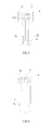
- Fig.1 is a structural schematic view of a baseplate supporting device according to an embodiment of present invention, showing a baseplate being placed on a baseplate support member of the baseplate supporting device.
- the baseplate supporting device comprises a baseplate support member 12 and a baseplate supporting pin.
- the baseplate supporting pin is provided to ascend or descend through an opening formed in the baseplate supporting member, so as to support the baseplate 11 on the baseplate supporting pin or place the baseplate on the baseplate support member 12.
- the baseplate supporting pin comprises: a pin body 10; a heating device 2 built in the pin body 10; and a first control unit 3 electrically connected to the heating device 2 for controlling the heating device.
- the heating device 2 may be arranged to be adjacent to top end of the pin body to be contacted by the baseplate.
- the baseplate supporting pin may provide a heating-up.
- electrical current is regulated by the first control unit 3, such that the heating device 2 inside of the baseplate supporting pin heats up to a certain temperature so as to match the heating temperature of the baseplate support member 12 around it.
- homogeneity of film quality may be improved, thereby enhancing the electrical property of TFT in the region of the baseplate supporting pin, reducing visual unevenness and increasing the product yield.
- the pin body 10 may comprise ceramic materials, and the heating device 2 is embedded in the pin body 10.
- a heating wire or an electromagnetic heating device, or other devices suitable for heating the pin body may be used.
- the first control unit 3 controls the heating device 2 to heat up, the heating device 2 firstly heats the pin body 10, and subsequently the heated pin body 10 may heat the baseplate (for example, a glass substrate) 11.
- the baseplate supporting pin may further comprise: a temperature sensing device 4 arranged within the pin body 10 for sensing a temperature of a region around the baseplate supporting pin; and a second control unit 8 signalingly coupled to the first control unit 3 and the temperature sensing device 4 respectively, for sending control signals to the first control unit 3 based on temperature signals received from the temperature sensing device 4.
- the first control unit 3 controls the heating device 2, for example, controls the heating device 2 to heat-up, according to control signals received from the second control unit 8.
- the first control unit 3 may control the heating device 2 based on an actual temperature of the baseplate support member 12 around the baseplate supporting pin, such that the temperature of the pin body 10 matches the ambient temperature.
- the temperature sensing device 4 may be various kinds of devices, for example, a thermocouple or a temperature probe.
- the second control unit 8 may be a information receiving and processing center, such as, a control centre for a console apparatus, which can receive information from the temperature sensing device and process the same, then send a control signal to the first control unit 3 such that the first control unit 3 performs a heating-up control of the heating device 2.
- the temperature sensing device 4 may be signalingly coupled, as an independently working device, to the second control unit 8. As shown in Fig.1 , when in use, the temperature sensing device 4 senses a temperature of a region of the baseplate 11 corresponding to the baseplate supporting pin, and sends data to the second control unit 8. Preferably, the temperature sensing device 4 is arranged to be adjacent to the top end of the pin body 10 to be contacted by the baseplate and arranged at a periphery of this top end.
- Other sensing devices also may be provided for measuring temperatures of other heated zones of the baseplate 11, and measurements are sent to the second control unit 8.
- the second control unit 8 may compare the above two measurements with each other, and then feed back instructions to the first control unit 3 which controls the heating device 2 inside of the baseplate supporting pin, and the first control unit 3 regulates the temperature of the baseplate supporting pin so as to make the temperature of the region of the baseplate 11 corresponding to the baseplate supporting pin 11 consistent with other heated zones of the baseplate 11.
- the pin body 10 needs to be cooled-down along with the baseplate support member 12 when the baseplate support member 12 is cooled-down.
- the baseplate supporting pin may further comprise: a cooling unit located in the pin body 10; and a third control unit 6 connected with the cooling unit, for controlling the cooling unit so as to cool the pin body, wherein the second control unit 8 is signalingly couple to the third control unit 6 so as to control the cooling unit.
- Fig.4 is a structural schematic view of a baseplate supporting pin according to an embodiment of present invention.
- the cooling unit may be a cooling liquid duct 7.
- the cooling liquid duct 7 may be evenly built in the pin body 10 as a separate pipeline; and by flowing the low-temperature liquid inside the pipelines, the pin body 10 may be cooled-down quickly.
- the interior of the pin body 10 is directly formed with a cooling liquid duct having a channel structure, such that the cooling liquid flows into the cooling liquid duct, which may achieve cooling-down effect in a similar way.
- the inflow/outflow of the cooling liquid into/from the pin body 10 is accomplished by the third control unit 6.
- the Third control unit 6 is a cooling regulating device, for example, a solenoid valve.
- the third control unit 6 is signalingly coupled with the second control unit 8, and based on the information fed back from the second control unit 8, flow regulation of the cooling medium may be carried out, thereby achieving the purpose of being cooled-down and realizing the desired temperature control.
- the specific medium flowing in the cooling liquid duct 7 may be liquid mediums capable of achieving a temperature drop, such as water, oil or the like.
- the cooling liquid duct 7 should not be sandwiched between the top end of the pin body and the heating device 2. Otherwise, the thermal radiation would be affected and the liquid within the cooling liquid duct 7 would be heated to expand, causing pipeline fracture. Therefore, the cooling liquid duct 7 is preferably provided to be farther from the top end of the pin body 10 than the heating device 2. As an example, as shown in Fig.4 , the cooling liquid ducts 7 may be adhered to the sidewall of the hollow cavity of the pin body and arranged in an encircling way.
- the cooling liquid ducts 7 protrude from the bottom of the pin body and provided with solenoid valves controlled by the second control unit 6, thus it's possible to achieve regulation of the heating-up or cooling-down of the baseplate supporting pin through cooperation with the temperature sensing devices and the heating device 2.
- the pin body may be designed to have a hollow cavity adjacent to its top end, and the heating device 2 and the temperature sensing device 4 are provided in the hollow cavity adjacent to the top end of the pin body.
- the Heating device 2 is electrically connected to the first control unit 3, and is controlled by the first control unit 3 to achieve the heating-up or cooling-down.
- the heating device 2 needs to be spaced away from the top end of the pin body by a certain distance, without any direct contact.
- the top end of the pin body is heated with irradiation, thereby performing heat transfer to the baseplate 1 contacted thereto and heating-up the baseplate 11.
- cooling unit may be provided in the hollow cavity of the pin body, for example, including a cooling gas intake pipe 51 for letting in the cooling gas and a cooling gas exhaust pipe 52 for venting cooling gas.
- a cooling gas intake pipe 51 for letting in the cooling gas
- a cooling gas exhaust pipe 52 for venting cooling gas.
- Cooling gas intake pipe 51 and the cooling gas exhaust pipe 52 are provided with a third control unit (for example, a solenoid valve) 6 outside of the baseplate supporting pin, the third control unit 6 cooperates with the temperature sensing device 4 and the heating device 2 to achieve the regulation of heating-up or cooling-down of the baseplate supporting pin.
- a third control unit for example, a solenoid valve
- a multi-orifice gas-expelling apparatus may be provided at the distal end of the cooling gas intake pipe 51, so as to cool-down the top end of the baseplate supporting pin uniformly.
- the multi-orifice gas-expelling apparatus may be a tubular structure 511 with several air vents, as shown in Fig.2 . That is, several rows of through holes are opened simultaneously at the pipe wall of one pipeline, each of which may transport cooling gas outwards, thus enlarging the venting area and cooling the baseplate supporting pin more rapidly.
- the multi-orifice gas-expelling apparatus may also be a sprayer device 512 with several air vents, as shown in Fig.3 . Its concrete configuration is similar to that of a shower sprayer, wherein the through holes thereon face directly towards the top end of the baseplate supporting pin, and its cooling-down effect is much more obvious.
- the baseplate supporting pin by providing a heating device, a temperature sensing device for measuring an ambient temperature and a cooling-down device within the baseplate supporting pin, a better temperature regulation of the baseplate supporting pin can be achieved, such that the following cases would not occur: an overlow local temperature appears for the baseplate when being heated, causing a bad film quality and a depressed electrical property of the TFT, thereby reducing visual unevenness presented by the finished liquid crystal display, enhancing the yield of product, reducing the possibility of producing defective products, and saving cost.
Landscapes
- Physics & Mathematics (AREA)
- Nonlinear Science (AREA)
- Chemical & Material Sciences (AREA)
- Crystallography & Structural Chemistry (AREA)
- General Physics & Mathematics (AREA)
- Optics & Photonics (AREA)
- Container, Conveyance, Adherence, Positioning, Of Wafer (AREA)
- Liquid Crystal (AREA)
- Exposure Of Semiconductors, Excluding Electron Or Ion Beam Exposure (AREA)
- Devices For Use In Laboratory Experiments (AREA)
Abstract
Description
- The present invention relates to a baseplate supporting pin as well as a baseplate supporting device using the baseplate supporting pin.
- The production line for the liquid crystal display usually achieves film formation by heating the baseplate. The baseplate needs to be placed on the baseplate support member and heated with heating elements interior of the baseplate support member, while before heating, the baseplate needs to be placed on the baseplate supporting pins in advance, and descent to the upper surface of the baseplate support member by ascending and descending of the baseplate supporting pin, and then achieve the heating process.
- The baseplate supporting pin presently used in the production line is made from temperature-uncontrollable solid materials, such that two situations would occur during the actual process of heating the baseplate:
- The first situation is that the baseplate supporting pin contacts with the baseplate when heating the baseplate, and in this case, the baseplate supporting pin has a temperature lower than the temperature of the surrounding baseplates and would absorp heat from the heated baseplate by heat transfer, causing, a bad film quality and a depressed electrical property of the thin film transistor (TFT);
- The second situation is that the baseplate supporting pin is spaced away from the heated baseplate by a certain distance, and in this case, the pore for receiving the baseplate supporting pin has a temperature inconsistent with ambient temperature, similarly causing, for a portion of the baseplate at the pore, a bad film quality and a depressed electrical property of the TFT.
- The above two situations would cause such a result that the finished liquid crystal display presents an uneven visual sense, reducing the yield of the production line, and therefore needs for a novel design capable of depressing such effects exist.
- According to embodiments of present invention, a baseplate supporting pin is provided, which comprises: a pin body; a heating device embedded into the pin body; and a first control unit electrically connected to the heating device for controlling the heating device.
- Preferably, the heating device is arranged to be adjacent to top end of the pin body to be contacted by the baseplate.
- Preferably, the baseplate supporting pin may further comprise: a temperature sensing device, arranged within the pin body for sensing a temperature of a region around the baseplate supporting pin; a second control unit signalingly coupled to the first control unit and the temperature sensing device respectively, for sending control signals to the first control unit based on temperature signals received from the temperature sensing device so as to control the heating device.
- According to some embodiments, the baseplate supporting pin may further comprise: a cooling unit located in the pin body; and a third control unit connected with the cooling unit, for controlling the cooling unit to cool the pin body, wherein, the second control unit is signalingly coupled to the third control unit so as to control the cooling unit.
- The cooling unit may comprise for example a cooling liquid duct.
- Preferably, the cooling liquid duct is provided to be farther from the top end of the pin body than the heating device.
- According to some embodiments, the cooling liquid duct may be a seperate pipeline embedded in the pin body, or a channel structure directly opened in the pin body.
- Additionally or alternatively, the cooling unit may comprise a cooling gas intake pipe and a cooling gas exhaust pipe.
- Preferably, the distal end of the cooling gas intake pipe is provided with a multi-orifice gas-expelling apparatus which is a tubular structure with several air vents or a sprayer device with several air vents.
- Preferably, the temperature sensing device is arranged to be adjacent to the top end of the pin body contacting with the baseplate and arranged at a periphery of this top end.
- According to some embodiments, the pin body may comprise a hollow cavity adjacent to the top end thereof, and the heating device and the temperature sensing device may be located within the hollow cavity.
- The third control unit is for example a solenoid valve.
- The temperature sensing device is for example a thermocouple.
- The heating device is for example a heating wire or an electromagnetic heating device.
- According to embodiments of present invention, a baseplate supporting device is further provided, which comprises: a baseplate support member; and a baseplate supporting pin, provided to ascend or descend through an opening formed in the baseplate supporting member so as to support the baseplate thereon or place the baseplate on the baseplate support member, wherein the baseplate supporting pin comprises: a pin body; a heating device built in the pin body; and a first control unit electrically connected to the heating device for controlling the heating device.
- In order to describe the technical solution of the embodiment of present invention more clearly, a brief introduction will be made of the attached drawings of the embodiments. Obviously, the drawings described below relate to only some embodiments of present invention, rather than limiting the present invention.
-
Fig.1 is a structural schematic view of a baseplate supporting device according to an embodiment of present invention, showing a baseplate being placed on the baseplate support member of the baseplate supporting device; -
Fig.2 is a structural schematic view of a baseplate supporting pin according to an embodiment of present invention; -
Fig.3 is a structural schematic view of a baseplate supporting pin according to an embodiment of present invention; -
Fig.4 is a structural schematic view of a baseplate supporting pin according to an embodiment of present invention. -
- 2-
- Heating device
- 3-
- First control unit
- 12-
- Baseplate support member
- 11-
- Baseplate
- 4-
- Temperature sensing device
- 8-
- Second control unit
- 7-
- Cooling liquid duct
- 511-
- Tubular structure
- 512-
- Sprayer device
- 6-
- Third control unit
- 51-
- Cooling gas intake pipe
- 52-
- Cooling gas exhaust pipe
- 10-
- Pin body
- To make clearer the object, technical solutions and advantages of the embodiments of present invention, a clear and full description of the technical solution of the embodiment of present invention will be made with reference to the accompanying drawings of the embodiment of present invention. Obviously, the described embodiments are merely part of the embodiments of the present invention, but not all the embodiments. Based on the described embodiments of present invention, all the other embodiments acquired by the ordinary skilled in this art, without any creative labor, fall into the protective scope of the present invention.
- Detail description of the embodiments of present invention will be made in the following, and examples thereof are illustrated in the drawings, throughout which identical or similar elements or elements of identical or similar functions are represented with identical or similar reference numerals.
- In the description of the present invention, the terms "upper", "lower", "above", "below" and so on just refer to oriental or positional relationships based on the illustration of the drawings, and only for the purpose of facilitating description of the present invention, rather than limiting the configuration and operation of the present invention to specific orientation, thereby should not be regarded as limitation of the present invention.
-
Fig.1 is a structural schematic view of a baseplate supporting device according to an embodiment of present invention, showing a baseplate being placed on a baseplate support member of the baseplate supporting device. As shown in the Figs, the baseplate supporting device comprises abaseplate support member 12 and a baseplate supporting pin. The baseplate supporting pin is provided to ascend or descend through an opening formed in the baseplate supporting member, so as to support thebaseplate 11 on the baseplate supporting pin or place the baseplate on thebaseplate support member 12. - As shown in
fig.1 , the baseplate supporting pin comprises: apin body 10; aheating device 2 built in thepin body 10; and a first control unit 3 electrically connected to theheating device 2 for controlling the heating device. - The
heating device 2 may be arranged to be adjacent to top end of the pin body to be contacted by the baseplate. - The baseplate supporting pin may provide a heating-up. During heating of the baseplate, electrical current is regulated by the first control unit 3, such that the
heating device 2 inside of the baseplate supporting pin heats up to a certain temperature so as to match the heating temperature of thebaseplate support member 12 around it. By heating theentire baseplate 11, homogeneity of film quality may be improved, thereby enhancing the electrical property of TFT in the region of the baseplate supporting pin, reducing visual unevenness and increasing the product yield. - In embodiments of present invention, the
pin body 10 may comprise ceramic materials, and theheating device 2 is embedded in thepin body 10. As to selection of theheating device 2, a heating wire or an electromagnetic heating device, or other devices suitable for heating the pin body may be used. When the first control unit 3 controls theheating device 2 to heat up, theheating device 2 firstly heats thepin body 10, and subsequently theheated pin body 10 may heat the baseplate (for example, a glass substrate) 11. - In order for the first control unit 3 of the above embodiment be able to control temperatures more accurately, as shown in
Fig.1 , the baseplate supporting pin provided by the present invention may further comprise:
atemperature sensing device 4 arranged within thepin body 10 for sensing a temperature of a region around the baseplate supporting pin; and
asecond control unit 8 signalingly coupled to the first control unit 3 and thetemperature sensing device 4 respectively, for sending control signals to the first control unit 3 based on temperature signals received from thetemperature sensing device 4. - Accordingly, the first control unit 3 controls the
heating device 2, for example, controls theheating device 2 to heat-up, according to control signals received from thesecond control unit 8. - As such, the first control unit 3 may control the
heating device 2 based on an actual temperature of thebaseplate support member 12 around the baseplate supporting pin, such that the temperature of thepin body 10 matches the ambient temperature. - The
temperature sensing device 4 may be various kinds of devices, for example, a thermocouple or a temperature probe. Thesecond control unit 8 may be a information receiving and processing center, such as, a control centre for a console apparatus, which can receive information from the temperature sensing device and process the same, then send a control signal to the first control unit 3 such that the first control unit 3 performs a heating-up control of theheating device 2. - The
temperature sensing device 4 may be signalingly coupled, as an independently working device, to thesecond control unit 8. As shown inFig.1 , when in use, thetemperature sensing device 4 senses a temperature of a region of thebaseplate 11 corresponding to the baseplate supporting pin, and sends data to thesecond control unit 8. Preferably, thetemperature sensing device 4 is arranged to be adjacent to the top end of thepin body 10 to be contacted by the baseplate and arranged at a periphery of this top end. - Other sensing devices also may be provided for measuring temperatures of other heated zones of the
baseplate 11, and measurements are sent to thesecond control unit 8. Thesecond control unit 8 may compare the above two measurements with each other, and then feed back instructions to the first control unit 3 which controls theheating device 2 inside of the baseplate supporting pin, and the first control unit 3 regulates the temperature of the baseplate supporting pin so as to make the temperature of the region of thebaseplate 11 corresponding to thebaseplate supporting pin 11 consistent with other heated zones of thebaseplate 11. - The
pin body 10 needs to be cooled-down along with thebaseplate support member 12 when thebaseplate support member 12 is cooled-down. The baseplate supporting pin according to embodiments of present invention may further comprise: a cooling unit located in thepin body 10; and athird control unit 6 connected with the cooling unit, for controlling the cooling unit so as to cool the pin body, wherein thesecond control unit 8 is signalingly couple to thethird control unit 6 so as to control the cooling unit. -
Fig.4 is a structural schematic view of a baseplate supporting pin according to an embodiment of present invention. In the embodiment ofFig.4 , the cooling unit may be a coolingliquid duct 7. The coolingliquid duct 7 may be evenly built in thepin body 10 as a separate pipeline; and by flowing the low-temperature liquid inside the pipelines, thepin body 10 may be cooled-down quickly. Of course, it is also possible that the interior of thepin body 10 is directly formed with a cooling liquid duct having a channel structure, such that the cooling liquid flows into the cooling liquid duct, which may achieve cooling-down effect in a similar way. The inflow/outflow of the cooling liquid into/from thepin body 10 is accomplished by thethird control unit 6. TheThird control unit 6 is a cooling regulating device, for example, a solenoid valve. Thethird control unit 6 is signalingly coupled with thesecond control unit 8, and based on the information fed back from thesecond control unit 8, flow regulation of the cooling medium may be carried out, thereby achieving the purpose of being cooled-down and realizing the desired temperature control. The specific medium flowing in the coolingliquid duct 7 may be liquid mediums capable of achieving a temperature drop, such as water, oil or the like. - Due to the fact that the
heating device 2 is located adjacent to the top end of thepin body 10 to be contacted by the baseplate, the coolingliquid duct 7 should not be sandwiched between the top end of the pin body and theheating device 2. Otherwise, the thermal radiation would be affected and the liquid within the coolingliquid duct 7 would be heated to expand, causing pipeline fracture. Therefore, the coolingliquid duct 7 is preferably provided to be farther from the top end of thepin body 10 than theheating device 2. As an example, as shown inFig.4 , the coolingliquid ducts 7 may be adhered to the sidewall of the hollow cavity of the pin body and arranged in an encircling way. The coolingliquid ducts 7 protrude from the bottom of the pin body and provided with solenoid valves controlled by thesecond control unit 6, thus it's possible to achieve regulation of the heating-up or cooling-down of the baseplate supporting pin through cooperation with the temperature sensing devices and theheating device 2. - In one embodiment of the present invention, as shown in
Fig.1 , the pin body may be designed to have a hollow cavity adjacent to its top end, and theheating device 2 and thetemperature sensing device 4 are provided in the hollow cavity adjacent to the top end of the pin body. TheHeating device 2 is electrically connected to the first control unit 3, and is controlled by the first control unit 3 to achieve the heating-up or cooling-down. When assembled, theheating device 2 needs to be spaced away from the top end of the pin body by a certain distance, without any direct contact. During the heating process, the top end of the pin body is heated with irradiation, thereby performing heat transfer to the baseplate 1 contacted thereto and heating-up thebaseplate 11. Another situation may be that, when the baseplate supporting pin retracts into the opening of thebaseplate support member 12, the top end of the pin body does not contact with thebaseplate 11, but with a certain distance therebetween. In such case, the heated top end of the pin body would cause thermal radiation to thebaseplate 11, and in this manner, it's also possible to heat thebaseplate 11. - Working principles of the
heating device 2 and thetemperature sensing device 4 of the baseplate supporting pin have been described with reference to the above embodiments. For the purpose of a better match between the temperature regulation of the baseplate supporting pin and the temperature in other zones of thebaseplate 11, additionally or alternatively, another cooling unit may be provided in the hollow cavity of the pin body, for example, including a coolinggas intake pipe 51 for letting in the cooling gas and a coolinggas exhaust pipe 52 for venting cooling gas. As shown inFig.1 , when the hollow cavity of the pin body is fed with a cooling gas, the temperature of the baseplate supporting pin may be lowered rapidly. When other zones of thebaseplate 11 is relatively low, it's not necessarily sufficient to meet matching requirement only by cooling theheating device 2 at a room temperature, and therefore, a device allowing a cooling gas to be fed into is added such that the cooling gas may assist the heating device to be cooled down rapidly. The Coolinggas intake pipe 51 and the coolinggas exhaust pipe 52 are provided with a third control unit (for example, a solenoid valve) 6 outside of the baseplate supporting pin, thethird control unit 6 cooperates with thetemperature sensing device 4 and theheating device 2 to achieve the regulation of heating-up or cooling-down of the baseplate supporting pin. - A multi-orifice gas-expelling apparatus may be provided at the distal end of the cooling
gas intake pipe 51, so as to cool-down the top end of the baseplate supporting pin uniformly. There may be various specific configurations for the multi-orifice gas-expelling apparatus. For example, it may be atubular structure 511 with several air vents, as shown inFig.2 . That is, several rows of through holes are opened simultaneously at the pipe wall of one pipeline, each of which may transport cooling gas outwards, thus enlarging the venting area and cooling the baseplate supporting pin more rapidly. In addition, the multi-orifice gas-expelling apparatus may also be asprayer device 512 with several air vents, as shown inFig.3 . Its concrete configuration is similar to that of a shower sprayer, wherein the through holes thereon face directly towards the top end of the baseplate supporting pin, and its cooling-down effect is much more obvious. - In the baseplate supporting pin according to embodiments of present invention, by providing a heating device, a temperature sensing device for measuring an ambient temperature and a cooling-down device within the baseplate supporting pin, a better temperature regulation of the baseplate supporting pin can be achieved, such that the following cases would not occur: an overlow local temperature appears for the baseplate when being heated, causing a bad film quality and a depressed electrical property of the TFT, thereby reducing visual unevenness presented by the finished liquid crystal display, enhancing the yield of product, reducing the possibility of producing defective products, and saving cost.Although embodiments of present invention have been illustrated and described, various alteration, adaptation, substitution and modification could be made to these embodiments without departing from the principle and purpose of the present invention as would be understood by the skill in this art, the scope of the present invention is defined by the claims and its equivalent.
Claims (15)
- A baseplate supporting pin, comprising a pin body, wherein the baseplate supporting pin further comprises:a heating device built in the pin body, anda first control unit electrically connected to the heating device for controlling the heating device.
- The baseplate supporting pin according to claim 1, wherein the heating device is arranged to be adjacent to top end of the pin body to be contacted by the baseplate.
- The baseplate supporting pin according to claim 1, further comprising:a temperature sensing device arranged within the pin body for sensing a temperature of a region around the baseplate supporting pin;a second control unit signalingly coupled to the first control unit and the temperature sensing device respectively, for sending control signals to the first control unit based on temperature signals received from the temperature sensing device so as to control the heating device.
- The baseplate supporting pin according to claim 3, further comprising:a cooling unit located in the pin body; anda third control unit connected with the cooling unit, for controlling the cooling unit so as to cool the pin body,wherein the second control unit is signalingly coupled to the third control unit to control the cooling unit.
- The baseplate supporting pin according to claim 4, wherein the cooling unit comprises a cooling liquid duct.
- The baseplate supporting pin according to claim 5, wherein the cooling liquid duct is arranged to be farther from the top end of the pin body than the heating device.
- The baseplate supporting pin according to claim 5 or 6, wherein the cooling liquid duct is a pipeline embedded in the pin body, or a channel structure directly opened in the pin body.
- The baseplate supporting pin according to claim 4, wherein the cooling unit comprises a cooling gas intake pipe and a cooling gas exhaust pipe.
- The baseplate supporting pin according to claim 8, wherein the distal end of the cooling gas intake pipe is provided with multi-orifice gas-expelling apparatus, which is a tubular structure with several air vents or a sprayer device with several air vents.
- The baseplate supporting pin according to any one of claims 3-9, wherein the temperature sensing device is arranged to be adjacent to the top end of the pin body to be contacted by the baseplate and located at a periphery of the top end.
- The baseplate supporting pin according to claim 10, wherein the pin body has a hollow cavity adjacent to the top end thereof, and the heating device and the temperature sensing device are located within the hollow cavity.
- The baseplate supporting pin according to any one of claims 4-9, wherein the third control unit is a solenoid valve.
- The baseplate supporting pin according to any one of claims 3-12, wherein the temperature sensing device is a thermocouple.
- The baseplate supporting pin according to any one of previous claims, wherein the heating device is a heating wire or an electromagnetic heating device.
- A baseplate supporting device, comprising:a baseplate support member; anda baseplate supporting pin, configured to ascend or descend through an opening formed in the baseplate supporting member so as to support the baseplate thereon or place the baseplate on the baseplate support member,wherein the baseplate supporting pin comprises: a pin body; a heating device built in the pin body; and a first control unit electrically connected to the heating device for controlling the heating device.
Applications Claiming Priority (2)
| Application Number | Priority Date | Filing Date | Title |
|---|---|---|---|
| CN2012201604861U CN202796877U (en) | 2012-04-16 | 2012-04-16 | Substrate support pin |
| PCT/CN2013/072891 WO2013155913A1 (en) | 2012-04-16 | 2013-03-19 | Substrate support pin and substrate support device adopting substrate support pin |
Publications (3)
| Publication Number | Publication Date |
|---|---|
| EP2840601A1 true EP2840601A1 (en) | 2015-02-25 |
| EP2840601A4 EP2840601A4 (en) | 2016-01-06 |
| EP2840601B1 EP2840601B1 (en) | 2020-11-11 |
Family
ID=47824081
Family Applications (1)
| Application Number | Title | Priority Date | Filing Date |
|---|---|---|---|
| EP13734304.2A Not-in-force EP2840601B1 (en) | 2012-04-16 | 2013-03-19 | Substrate support pin and substrate support device adopting substrate support pin |
Country Status (6)
| Country | Link |
|---|---|
| US (1) | US9414439B2 (en) |
| EP (1) | EP2840601B1 (en) |
| JP (1) | JP2015519730A (en) |
| KR (1) | KR101485726B1 (en) |
| CN (1) | CN202796877U (en) |
| WO (1) | WO2013155913A1 (en) |
Families Citing this family (9)
| Publication number | Priority date | Publication date | Assignee | Title |
|---|---|---|---|---|
| CN202796877U (en) | 2012-04-16 | 2013-03-13 | 京东方科技集团股份有限公司 | Substrate support pin |
| CN103309090A (en) * | 2013-06-20 | 2013-09-18 | 深圳市华星光电技术有限公司 | Device and method for supporting substrate in ultraviolet curing |
| CN103383508B (en) * | 2013-07-22 | 2015-12-23 | 京东方科技集团股份有限公司 | A kind of method under liquid crystal dripping device and liquid crystal drop |
| CN106607320B (en) * | 2016-12-22 | 2019-10-01 | 武汉华星光电技术有限公司 | Thermal vacuum drying device suitable for flexible base board |
| JP7030557B2 (en) * | 2018-02-27 | 2022-03-07 | 日本特殊陶業株式会社 | Holding device |
| JP2020150009A (en) * | 2019-03-11 | 2020-09-17 | 東京エレクトロン株式会社 | Substrate processing equipment and substrate processing method |
| KR102325984B1 (en) * | 2019-11-04 | 2021-11-12 | 한국표준과학연구원 | Calibrator with Active Point Heaters for Wafer Temperature Sensor |
| JP7578359B2 (en) | 2020-07-10 | 2024-11-06 | 東京エレクトロン株式会社 | Mounting table device and substrate processing device |
| CN115973773B (en) * | 2022-12-19 | 2026-01-13 | 京东方科技集团股份有限公司 | Support transfer device, substrate transfer method, and curing system |
Family Cites Families (13)
| Publication number | Priority date | Publication date | Assignee | Title |
|---|---|---|---|---|
| JP2618698B2 (en) * | 1988-09-08 | 1997-06-11 | 東京エレクトロン株式会社 | Heating device and heating method |
| US6415858B1 (en) * | 1997-12-31 | 2002-07-09 | Temptronic Corporation | Temperature control system for a workpiece chuck |
| KR20030069272A (en) | 2002-02-19 | 2003-08-27 | 삼성전자주식회사 | Semiconductor device and Method of fabricating the same |
| KR100840720B1 (en) * | 2002-08-30 | 2008-06-23 | 삼성전자주식회사 | Baking device |
| KR100964619B1 (en) * | 2003-10-06 | 2010-06-22 | 삼성전자주식회사 | Lift pins, lifting devices comprising them |
| JP2006324559A (en) * | 2005-05-20 | 2006-11-30 | Dainippon Screen Mfg Co Ltd | Substrate drying apparatus and substrate drying method |
| WO2007013605A1 (en) | 2005-07-28 | 2007-02-01 | Tokyo Electron Limited | Substrate processing method and substrate processing apparatus |
| JP5025109B2 (en) * | 2005-08-26 | 2012-09-12 | 東京エレクトロン株式会社 | Substrate mounting mechanism, substrate processing apparatus, and method of manufacturing substrate mounting mechanism |
| KR101402875B1 (en) * | 2006-12-11 | 2014-06-03 | 엘아이지에이디피 주식회사 | Lift pin, heater for lift pin and manufacturing device for FPD having the same |
| KR100905899B1 (en) * | 2007-04-27 | 2009-07-02 | 세메스 주식회사 | Substrate lifting unit, substrate processing apparatus and method using same |
| WO2011030607A1 (en) * | 2009-09-10 | 2011-03-17 | シャープ株式会社 | Drying device |
| WO2011136604A2 (en) * | 2010-04-30 | 2011-11-03 | 주식회사 테라세미콘 | Substrate treating apparatus |
| CN202796877U (en) | 2012-04-16 | 2013-03-13 | 京东方科技集团股份有限公司 | Substrate support pin |
-
2012
- 2012-04-16 CN CN2012201604861U patent/CN202796877U/en not_active Expired - Fee Related
-
2013
- 2013-03-19 EP EP13734304.2A patent/EP2840601B1/en not_active Not-in-force
- 2013-03-19 KR KR1020137020461A patent/KR101485726B1/en not_active Expired - Fee Related
- 2013-03-19 JP JP2015504848A patent/JP2015519730A/en active Pending
- 2013-03-19 US US13/984,387 patent/US9414439B2/en not_active Expired - Fee Related
- 2013-03-19 WO PCT/CN2013/072891 patent/WO2013155913A1/en not_active Ceased
Also Published As
| Publication number | Publication date |
|---|---|
| US20140054282A1 (en) | 2014-02-27 |
| EP2840601A4 (en) | 2016-01-06 |
| KR101485726B1 (en) | 2015-01-28 |
| EP2840601B1 (en) | 2020-11-11 |
| JP2015519730A (en) | 2015-07-09 |
| WO2013155913A1 (en) | 2013-10-24 |
| KR20140001994A (en) | 2014-01-07 |
| CN202796877U (en) | 2013-03-13 |
| US9414439B2 (en) | 2016-08-09 |
Similar Documents
| Publication | Publication Date | Title |
|---|---|---|
| US9414439B2 (en) | Baseplate supporting pin and baseplate supporting device using the same | |
| EP2355133A2 (en) | Substrate heating apparatus, substrate heating method and substrate processing system | |
| CN103760753B (en) | Substrate roasting device and temperature adjustment method thereof | |
| CN104911544B (en) | Temperature control disk | |
| US6353209B1 (en) | Temperature processing module | |
| KR101660968B1 (en) | Planar heater device for thermal process of substrate | |
| CN103309090A (en) | Device and method for supporting substrate in ultraviolet curing | |
| TWI759302B (en) | Heating apparatuses and methods for glass tubing manufacturing | |
| JP5897275B2 (en) | Temperature control unit, substrate mounting table, substrate processing apparatus, temperature control system, and substrate processing method | |
| CN102745889B (en) | Device and method for conducting baking treatment on glass substrate | |
| CN203578136U (en) | Supporting mechanism and coating supporting device | |
| CN105225983A (en) | The heater of coupling window and apply its reaction chamber | |
| CN205959102U (en) | Miniature control by temperature change chamber based on semiconductor refrigeration technology | |
| CN104576463A (en) | Rapid cooling and heat treatment system | |
| KR102190566B1 (en) | Substrate processing apparatus | |
| CN204303776U (en) | Fast cooling heat treatment system | |
| CN111063637A (en) | Heating device and control method thereof | |
| US9206065B2 (en) | Apparatus and method for baking glass substrate | |
| TWM499580U (en) | Temperature control device of heater of photoresist pre-baking furnace | |
| CN222507554U (en) | Silicon carbide etching device | |
| CN105088334A (en) | Top cover apparatus and technology equipment | |
| JP2015177024A (en) | Method for heat-treating a substrate, heat treatment apparatus and computer-readable recording medium | |
| EP1505636A2 (en) | Semiconductor substrate surface preparation using high temperature convection heating | |
| WO2018153151A1 (en) | Transfer platform, attaching device, and attaching method thereof | |
| EP4159411A1 (en) | Thermoforming device and thermoforming method |
Legal Events
| Date | Code | Title | Description |
|---|---|---|---|
| PUAI | Public reference made under article 153(3) epc to a published international application that has entered the european phase |
Free format text: ORIGINAL CODE: 0009012 |
|
| 17P | Request for examination filed |
Effective date: 20130715 |
|
| AK | Designated contracting states |
Kind code of ref document: A1 Designated state(s): AL AT BE BG CH CY CZ DE DK EE ES FI FR GB GR HR HU IE IS IT LI LT LU LV MC MK MT NL NO PL PT RO RS SE SI SK SM TR |
|
| AX | Request for extension of the european patent |
Extension state: BA ME |
|
| DAX | Request for extension of the european patent (deleted) | ||
| RA4 | Supplementary search report drawn up and despatched (corrected) |
Effective date: 20151209 |
|
| RIC1 | Information provided on ipc code assigned before grant |
Ipc: H01L 21/687 20060101AFI20151203BHEP Ipc: H01L 21/67 20060101ALI20151203BHEP Ipc: H05B 1/02 20060101ALI20151203BHEP |
|
| GRAP | Despatch of communication of intention to grant a patent |
Free format text: ORIGINAL CODE: EPIDOSNIGR1 |
|
| STAA | Information on the status of an ep patent application or granted ep patent |
Free format text: STATUS: GRANT OF PATENT IS INTENDED |
|
| INTG | Intention to grant announced |
Effective date: 20200603 |
|
| GRAS | Grant fee paid |
Free format text: ORIGINAL CODE: EPIDOSNIGR3 |
|
| GRAA | (expected) grant |
Free format text: ORIGINAL CODE: 0009210 |
|
| STAA | Information on the status of an ep patent application or granted ep patent |
Free format text: STATUS: THE PATENT HAS BEEN GRANTED |
|
| AK | Designated contracting states |
Kind code of ref document: B1 Designated state(s): AL AT BE BG CH CY CZ DE DK EE ES FI FR GB GR HR HU IE IS IT LI LT LU LV MC MK MT NL NO PL PT RO RS SE SI SK SM TR |
|
| REG | Reference to a national code |
Ref country code: GB Ref legal event code: FG4D |
|
| REG | Reference to a national code |
Ref country code: CH Ref legal event code: EP |
|
| REG | Reference to a national code |
Ref country code: AT Ref legal event code: REF Ref document number: 1334278 Country of ref document: AT Kind code of ref document: T Effective date: 20201115 |
|
| REG | Reference to a national code |
Ref country code: DE Ref legal event code: R096 Ref document number: 602013073971 Country of ref document: DE |
|
| REG | Reference to a national code |
Ref country code: IE Ref legal event code: FG4D |
|
| REG | Reference to a national code |
Ref country code: NL Ref legal event code: MP Effective date: 20201111 |
|
| REG | Reference to a national code |
Ref country code: AT Ref legal event code: MK05 Ref document number: 1334278 Country of ref document: AT Kind code of ref document: T Effective date: 20201111 |
|
| PG25 | Lapsed in a contracting state [announced via postgrant information from national office to epo] |
Ref country code: GR Free format text: LAPSE BECAUSE OF FAILURE TO SUBMIT A TRANSLATION OF THE DESCRIPTION OR TO PAY THE FEE WITHIN THE PRESCRIBED TIME-LIMIT Effective date: 20210212 Ref country code: PT Free format text: LAPSE BECAUSE OF FAILURE TO SUBMIT A TRANSLATION OF THE DESCRIPTION OR TO PAY THE FEE WITHIN THE PRESCRIBED TIME-LIMIT Effective date: 20210311 Ref country code: NO Free format text: LAPSE BECAUSE OF FAILURE TO SUBMIT A TRANSLATION OF THE DESCRIPTION OR TO PAY THE FEE WITHIN THE PRESCRIBED TIME-LIMIT Effective date: 20210211 Ref country code: RS Free format text: LAPSE BECAUSE OF FAILURE TO SUBMIT A TRANSLATION OF THE DESCRIPTION OR TO PAY THE FEE WITHIN THE PRESCRIBED TIME-LIMIT Effective date: 20201111 Ref country code: FI Free format text: LAPSE BECAUSE OF FAILURE TO SUBMIT A TRANSLATION OF THE DESCRIPTION OR TO PAY THE FEE WITHIN THE PRESCRIBED TIME-LIMIT Effective date: 20201111 |
|
| PG25 | Lapsed in a contracting state [announced via postgrant information from national office to epo] |
Ref country code: PL Free format text: LAPSE BECAUSE OF FAILURE TO SUBMIT A TRANSLATION OF THE DESCRIPTION OR TO PAY THE FEE WITHIN THE PRESCRIBED TIME-LIMIT Effective date: 20201111 Ref country code: LV Free format text: LAPSE BECAUSE OF FAILURE TO SUBMIT A TRANSLATION OF THE DESCRIPTION OR TO PAY THE FEE WITHIN THE PRESCRIBED TIME-LIMIT Effective date: 20201111 Ref country code: IS Free format text: LAPSE BECAUSE OF FAILURE TO SUBMIT A TRANSLATION OF THE DESCRIPTION OR TO PAY THE FEE WITHIN THE PRESCRIBED TIME-LIMIT Effective date: 20210311 Ref country code: SE Free format text: LAPSE BECAUSE OF FAILURE TO SUBMIT A TRANSLATION OF THE DESCRIPTION OR TO PAY THE FEE WITHIN THE PRESCRIBED TIME-LIMIT Effective date: 20201111 Ref country code: AT Free format text: LAPSE BECAUSE OF FAILURE TO SUBMIT A TRANSLATION OF THE DESCRIPTION OR TO PAY THE FEE WITHIN THE PRESCRIBED TIME-LIMIT Effective date: 20201111 Ref country code: BG Free format text: LAPSE BECAUSE OF FAILURE TO SUBMIT A TRANSLATION OF THE DESCRIPTION OR TO PAY THE FEE WITHIN THE PRESCRIBED TIME-LIMIT Effective date: 20210211 |
|
| REG | Reference to a national code |
Ref country code: LT Ref legal event code: MG9D |
|
| PG25 | Lapsed in a contracting state [announced via postgrant information from national office to epo] |
Ref country code: HR Free format text: LAPSE BECAUSE OF FAILURE TO SUBMIT A TRANSLATION OF THE DESCRIPTION OR TO PAY THE FEE WITHIN THE PRESCRIBED TIME-LIMIT Effective date: 20201111 |
|
| PG25 | Lapsed in a contracting state [announced via postgrant information from national office to epo] |
Ref country code: SK Free format text: LAPSE BECAUSE OF FAILURE TO SUBMIT A TRANSLATION OF THE DESCRIPTION OR TO PAY THE FEE WITHIN THE PRESCRIBED TIME-LIMIT Effective date: 20201111 Ref country code: RO Free format text: LAPSE BECAUSE OF FAILURE TO SUBMIT A TRANSLATION OF THE DESCRIPTION OR TO PAY THE FEE WITHIN THE PRESCRIBED TIME-LIMIT Effective date: 20201111 Ref country code: LT Free format text: LAPSE BECAUSE OF FAILURE TO SUBMIT A TRANSLATION OF THE DESCRIPTION OR TO PAY THE FEE WITHIN THE PRESCRIBED TIME-LIMIT Effective date: 20201111 Ref country code: EE Free format text: LAPSE BECAUSE OF FAILURE TO SUBMIT A TRANSLATION OF THE DESCRIPTION OR TO PAY THE FEE WITHIN THE PRESCRIBED TIME-LIMIT Effective date: 20201111 Ref country code: CZ Free format text: LAPSE BECAUSE OF FAILURE TO SUBMIT A TRANSLATION OF THE DESCRIPTION OR TO PAY THE FEE WITHIN THE PRESCRIBED TIME-LIMIT Effective date: 20201111 Ref country code: SM Free format text: LAPSE BECAUSE OF FAILURE TO SUBMIT A TRANSLATION OF THE DESCRIPTION OR TO PAY THE FEE WITHIN THE PRESCRIBED TIME-LIMIT Effective date: 20201111 |
|
| REG | Reference to a national code |
Ref country code: DE Ref legal event code: R097 Ref document number: 602013073971 Country of ref document: DE |
|
| PG25 | Lapsed in a contracting state [announced via postgrant information from national office to epo] |
Ref country code: DK Free format text: LAPSE BECAUSE OF FAILURE TO SUBMIT A TRANSLATION OF THE DESCRIPTION OR TO PAY THE FEE WITHIN THE PRESCRIBED TIME-LIMIT Effective date: 20201111 |
|
| PLBE | No opposition filed within time limit |
Free format text: ORIGINAL CODE: 0009261 |
|
| STAA | Information on the status of an ep patent application or granted ep patent |
Free format text: STATUS: NO OPPOSITION FILED WITHIN TIME LIMIT |
|
| 26N | No opposition filed |
Effective date: 20210812 |
|
| PG25 | Lapsed in a contracting state [announced via postgrant information from national office to epo] |
Ref country code: MC Free format text: LAPSE BECAUSE OF FAILURE TO SUBMIT A TRANSLATION OF THE DESCRIPTION OR TO PAY THE FEE WITHIN THE PRESCRIBED TIME-LIMIT Effective date: 20201111 Ref country code: NL Free format text: LAPSE BECAUSE OF FAILURE TO SUBMIT A TRANSLATION OF THE DESCRIPTION OR TO PAY THE FEE WITHIN THE PRESCRIBED TIME-LIMIT Effective date: 20201111 Ref country code: IT Free format text: LAPSE BECAUSE OF FAILURE TO SUBMIT A TRANSLATION OF THE DESCRIPTION OR TO PAY THE FEE WITHIN THE PRESCRIBED TIME-LIMIT Effective date: 20201111 Ref country code: AL Free format text: LAPSE BECAUSE OF FAILURE TO SUBMIT A TRANSLATION OF THE DESCRIPTION OR TO PAY THE FEE WITHIN THE PRESCRIBED TIME-LIMIT Effective date: 20201111 |
|
| REG | Reference to a national code |
Ref country code: CH Ref legal event code: PL |
|
| GBPC | Gb: european patent ceased through non-payment of renewal fee |
Effective date: 20210319 |
|
| PG25 | Lapsed in a contracting state [announced via postgrant information from national office to epo] |
Ref country code: ES Free format text: LAPSE BECAUSE OF FAILURE TO SUBMIT A TRANSLATION OF THE DESCRIPTION OR TO PAY THE FEE WITHIN THE PRESCRIBED TIME-LIMIT Effective date: 20201111 Ref country code: SI Free format text: LAPSE BECAUSE OF FAILURE TO SUBMIT A TRANSLATION OF THE DESCRIPTION OR TO PAY THE FEE WITHIN THE PRESCRIBED TIME-LIMIT Effective date: 20201111 |
|
| REG | Reference to a national code |
Ref country code: BE Ref legal event code: MM Effective date: 20210331 |
|
| PG25 | Lapsed in a contracting state [announced via postgrant information from national office to epo] |
Ref country code: GB Free format text: LAPSE BECAUSE OF NON-PAYMENT OF DUE FEES Effective date: 20210319 Ref country code: IE Free format text: LAPSE BECAUSE OF NON-PAYMENT OF DUE FEES Effective date: 20210319 Ref country code: FR Free format text: LAPSE BECAUSE OF NON-PAYMENT OF DUE FEES Effective date: 20210331 Ref country code: CH Free format text: LAPSE BECAUSE OF NON-PAYMENT OF DUE FEES Effective date: 20210331 Ref country code: LI Free format text: LAPSE BECAUSE OF NON-PAYMENT OF DUE FEES Effective date: 20210331 Ref country code: LU Free format text: LAPSE BECAUSE OF NON-PAYMENT OF DUE FEES Effective date: 20210319 |
|
| PG25 | Lapsed in a contracting state [announced via postgrant information from national office to epo] |
Ref country code: IS Free format text: LAPSE BECAUSE OF FAILURE TO SUBMIT A TRANSLATION OF THE DESCRIPTION OR TO PAY THE FEE WITHIN THE PRESCRIBED TIME-LIMIT Effective date: 20210311 |
|
| PG25 | Lapsed in a contracting state [announced via postgrant information from national office to epo] |
Ref country code: BE Free format text: LAPSE BECAUSE OF NON-PAYMENT OF DUE FEES Effective date: 20210331 |
|
| PG25 | Lapsed in a contracting state [announced via postgrant information from national office to epo] |
Ref country code: HU Free format text: LAPSE BECAUSE OF FAILURE TO SUBMIT A TRANSLATION OF THE DESCRIPTION OR TO PAY THE FEE WITHIN THE PRESCRIBED TIME-LIMIT; INVALID AB INITIO Effective date: 20130319 |
|
| PGFP | Annual fee paid to national office [announced via postgrant information from national office to epo] |
Ref country code: DE Payment date: 20230216 Year of fee payment: 11 |
|
| PG25 | Lapsed in a contracting state [announced via postgrant information from national office to epo] |
Ref country code: CY Free format text: LAPSE BECAUSE OF FAILURE TO SUBMIT A TRANSLATION OF THE DESCRIPTION OR TO PAY THE FEE WITHIN THE PRESCRIBED TIME-LIMIT Effective date: 20201111 |
|
| PG25 | Lapsed in a contracting state [announced via postgrant information from national office to epo] |
Ref country code: MK Free format text: LAPSE BECAUSE OF FAILURE TO SUBMIT A TRANSLATION OF THE DESCRIPTION OR TO PAY THE FEE WITHIN THE PRESCRIBED TIME-LIMIT Effective date: 20201111 |
|
| PG25 | Lapsed in a contracting state [announced via postgrant information from national office to epo] |
Ref country code: TR Free format text: LAPSE BECAUSE OF FAILURE TO SUBMIT A TRANSLATION OF THE DESCRIPTION OR TO PAY THE FEE WITHIN THE PRESCRIBED TIME-LIMIT Effective date: 20201111 |
|
| PG25 | Lapsed in a contracting state [announced via postgrant information from national office to epo] |
Ref country code: MT Free format text: LAPSE BECAUSE OF FAILURE TO SUBMIT A TRANSLATION OF THE DESCRIPTION OR TO PAY THE FEE WITHIN THE PRESCRIBED TIME-LIMIT Effective date: 20201111 |
|
| REG | Reference to a national code |
Ref country code: DE Ref legal event code: R119 Ref document number: 602013073971 Country of ref document: DE |
|
| PG25 | Lapsed in a contracting state [announced via postgrant information from national office to epo] |
Ref country code: DE Free format text: LAPSE BECAUSE OF NON-PAYMENT OF DUE FEES Effective date: 20241001 |
|
| PG25 | Lapsed in a contracting state [announced via postgrant information from national office to epo] |
Ref country code: DE Free format text: LAPSE BECAUSE OF NON-PAYMENT OF DUE FEES Effective date: 20241001 |