EP2839991A1 - Dispositif de traitement d'image et procédé d'aide à la conduite - Google Patents
Dispositif de traitement d'image et procédé d'aide à la conduite Download PDFInfo
- Publication number
- EP2839991A1 EP2839991A1 EP13777578.9A EP13777578A EP2839991A1 EP 2839991 A1 EP2839991 A1 EP 2839991A1 EP 13777578 A EP13777578 A EP 13777578A EP 2839991 A1 EP2839991 A1 EP 2839991A1
- Authority
- EP
- European Patent Office
- Prior art keywords
- color
- indicator
- captured image
- image processing
- processing apparatus
- Prior art date
- Legal status (The legal status is an assumption and is not a legal conclusion. Google has not performed a legal analysis and makes no representation as to the accuracy of the status listed.)
- Granted
Links
- 238000000034 method Methods 0.000 title claims description 32
- 238000003384 imaging method Methods 0.000 claims abstract description 16
- 230000000295 complement effect Effects 0.000 claims description 6
- 230000008859 change Effects 0.000 claims description 4
- 238000005286 illumination Methods 0.000 claims description 2
- 230000008569 process Effects 0.000 description 24
- 239000003086 colorant Substances 0.000 description 17
- 238000001514 detection method Methods 0.000 description 3
- 230000005540 biological transmission Effects 0.000 description 2
- 238000010586 diagram Methods 0.000 description 2
- 238000012986 modification Methods 0.000 description 2
- 230000004048 modification Effects 0.000 description 2
- 230000003287 optical effect Effects 0.000 description 2
- 230000008901 benefit Effects 0.000 description 1
- 230000000694 effects Effects 0.000 description 1
- 239000000446 fuel Substances 0.000 description 1
- 230000009467 reduction Effects 0.000 description 1
Images


Classifications
-
- B—PERFORMING OPERATIONS; TRANSPORTING
- B60—VEHICLES IN GENERAL
- B60R—VEHICLES, VEHICLE FITTINGS, OR VEHICLE PARTS, NOT OTHERWISE PROVIDED FOR
- B60R1/00—Optical viewing arrangements; Real-time viewing arrangements for drivers or passengers using optical image capturing systems, e.g. cameras or video systems specially adapted for use in or on vehicles
- B60R1/20—Real-time viewing arrangements for drivers or passengers using optical image capturing systems, e.g. cameras or video systems specially adapted for use in or on vehicles
- B60R1/22—Real-time viewing arrangements for drivers or passengers using optical image capturing systems, e.g. cameras or video systems specially adapted for use in or on vehicles for viewing an area outside the vehicle, e.g. the exterior of the vehicle
- B60R1/23—Real-time viewing arrangements for drivers or passengers using optical image capturing systems, e.g. cameras or video systems specially adapted for use in or on vehicles for viewing an area outside the vehicle, e.g. the exterior of the vehicle with a predetermined field of view
- B60R1/26—Real-time viewing arrangements for drivers or passengers using optical image capturing systems, e.g. cameras or video systems specially adapted for use in or on vehicles for viewing an area outside the vehicle, e.g. the exterior of the vehicle with a predetermined field of view to the rear of the vehicle
-
- G—PHYSICS
- G08—SIGNALLING
- G08G—TRAFFIC CONTROL SYSTEMS
- G08G1/00—Traffic control systems for road vehicles
- G08G1/09—Arrangements for giving variable traffic instructions
- G08G1/0962—Arrangements for giving variable traffic instructions having an indicator mounted inside the vehicle, e.g. giving voice messages
-
- G—PHYSICS
- G08—SIGNALLING
- G08G—TRAFFIC CONTROL SYSTEMS
- G08G1/00—Traffic control systems for road vehicles
- G08G1/16—Anti-collision systems
-
- G—PHYSICS
- G08—SIGNALLING
- G08G—TRAFFIC CONTROL SYSTEMS
- G08G1/00—Traffic control systems for road vehicles
- G08G1/16—Anti-collision systems
- G08G1/168—Driving aids for parking, e.g. acoustic or visual feedback on parking space
-
- G—PHYSICS
- G09—EDUCATION; CRYPTOGRAPHY; DISPLAY; ADVERTISING; SEALS
- G09G—ARRANGEMENTS OR CIRCUITS FOR CONTROL OF INDICATING DEVICES USING STATIC MEANS TO PRESENT VARIABLE INFORMATION
- G09G5/00—Control arrangements or circuits for visual indicators common to cathode-ray tube indicators and other visual indicators
- G09G5/02—Control arrangements or circuits for visual indicators common to cathode-ray tube indicators and other visual indicators characterised by the way in which colour is displayed
-
- B—PERFORMING OPERATIONS; TRANSPORTING
- B60—VEHICLES IN GENERAL
- B60R—VEHICLES, VEHICLE FITTINGS, OR VEHICLE PARTS, NOT OTHERWISE PROVIDED FOR
- B60R2300/00—Details of viewing arrangements using cameras and displays, specially adapted for use in a vehicle
- B60R2300/30—Details of viewing arrangements using cameras and displays, specially adapted for use in a vehicle characterised by the type of image processing
- B60R2300/307—Details of viewing arrangements using cameras and displays, specially adapted for use in a vehicle characterised by the type of image processing virtually distinguishing relevant parts of a scene from the background of the scene
-
- B—PERFORMING OPERATIONS; TRANSPORTING
- B60—VEHICLES IN GENERAL
- B60R—VEHICLES, VEHICLE FITTINGS, OR VEHICLE PARTS, NOT OTHERWISE PROVIDED FOR
- B60R2300/00—Details of viewing arrangements using cameras and displays, specially adapted for use in a vehicle
- B60R2300/80—Details of viewing arrangements using cameras and displays, specially adapted for use in a vehicle characterised by the intended use of the viewing arrangement
- B60R2300/802—Details of viewing arrangements using cameras and displays, specially adapted for use in a vehicle characterised by the intended use of the viewing arrangement for monitoring and displaying vehicle exterior blind spot views
-
- G—PHYSICS
- G08—SIGNALLING
- G08G—TRAFFIC CONTROL SYSTEMS
- G08G1/00—Traffic control systems for road vehicles
- G08G1/16—Anti-collision systems
- G08G1/165—Anti-collision systems for passive traffic, e.g. including static obstacles, trees
-
- G—PHYSICS
- G09—EDUCATION; CRYPTOGRAPHY; DISPLAY; ADVERTISING; SEALS
- G09G—ARRANGEMENTS OR CIRCUITS FOR CONTROL OF INDICATING DEVICES USING STATIC MEANS TO PRESENT VARIABLE INFORMATION
- G09G2320/00—Control of display operating conditions
- G09G2320/06—Adjustment of display parameters
- G09G2320/0613—The adjustment depending on the type of the information to be displayed
-
- G—PHYSICS
- G09—EDUCATION; CRYPTOGRAPHY; DISPLAY; ADVERTISING; SEALS
- G09G—ARRANGEMENTS OR CIRCUITS FOR CONTROL OF INDICATING DEVICES USING STATIC MEANS TO PRESENT VARIABLE INFORMATION
- G09G2320/00—Control of display operating conditions
- G09G2320/06—Adjustment of display parameters
- G09G2320/0666—Adjustment of display parameters for control of colour parameters, e.g. colour temperature
-
- G—PHYSICS
- G09—EDUCATION; CRYPTOGRAPHY; DISPLAY; ADVERTISING; SEALS
- G09G—ARRANGEMENTS OR CIRCUITS FOR CONTROL OF INDICATING DEVICES USING STATIC MEANS TO PRESENT VARIABLE INFORMATION
- G09G2340/00—Aspects of display data processing
- G09G2340/12—Overlay of images, i.e. displayed pixel being the result of switching between the corresponding input pixels
-
- G—PHYSICS
- G09—EDUCATION; CRYPTOGRAPHY; DISPLAY; ADVERTISING; SEALS
- G09G—ARRANGEMENTS OR CIRCUITS FOR CONTROL OF INDICATING DEVICES USING STATIC MEANS TO PRESENT VARIABLE INFORMATION
- G09G2380/00—Specific applications
- G09G2380/10—Automotive applications
Definitions
- the present invention relates to an image processing apparatus for superimposing an indicator on a captured image generated by imaging the vicinity of a vehicle, and also to an imaging apparatus and a drive assisting method.
- a vehicle drive assisting apparatus that, during running of a vehicle, displays a captured image of the vicinity of the vehicle imaged by an imaging apparatus mounted on the vehicle on a display apparatus installed in the vehicle.
- a driver by checking the captured image displayed on the display apparatus, may recognize obstacles in the vicinity of the vehicle while driving the vehicle and also, in parking, park the vehicle accurately and easily in a parking space.
- the drive assisting apparatus displays, in addition to the captured image of the vicinity of the vehicle, an indicator for assisting driving superimposed on the captured image (for example, Patent Document 1).
- the indicator superimposed on the captured image is, for example, a predicted path guide line of the vehicle.
- the captured image having the indicator superimposed thereon allows the driver to more accurately and easily recognize a distance between the vehicle and an object as well as a width of the vehicle.
- Patent Document 1 Japanese Patent Application Laid-Open Publication No. 2010-001020
- the indicator being displayed for its purpose, preferably stands out as much as possible against the captured image displayed as a background.
- the indicator is generally colored yellow or red, for example, for easy recognition to the driver.
- color of the captured image overall is sometimes similar to the color of the indicator.
- the captured image is entirely stained color of the light from the light sources and the color of the captured image may become similar to the color of the indicator.
- the driver may have difficulty in viewing the indicator.
- an object of the present invention in view of the above problem is to provide an image processing apparatus, an imaging apparatus and a drive assisting method for maintaining a visibility of the indicator when the color of the captured image is similar to the color of the indicator.
- an image processing apparatus includes:
- a second aspect of the present invention is the image processing apparatus, wherein the receiver is capable of receiving a lighting signal for lighting up a light source of the vehicle that emits illumination light in the first color to the vicinity of the vehicle, and the color determinator, when receiving the lighting signal, changes the color of the indicator to a second color.
- a third aspect of the present invention is the image processing apparatus, including a detector for detecting color of the subject based on the captured image generated while the light source is lit up, wherein the color determinator, when the color of the subject that is detected is similar to the second color, changes the color of the indicator to a third color.
- a fourth aspect of the present invention is the image processing apparatus, wherein the color determinator, at least one of when the superimposition of the indicator is carried out at nighttime and when the vehicle is located indoors, changes the color of the indicator from the first color.
- a fifth aspect of the present invention is the image processing apparatus, including a detector for detecting the color of the subject based on the captured image.
- a sixth aspect of the present invention is the image processing apparatus, wherein the color determinator changes the color of the indicator such that at least one of hue, brightness, and intensity of the color of the indicator differs from those of the color of the captured image.
- a seventh aspect of the present invention is the image processing apparatus, wherein the color determinator changes the color of the indicator to complementary color of the color of the subject.
- an imaging apparatus includes:
- a drive assisting method for implementing the present invention as a method includes:
- the imaging apparatus and the drive assisting method of the present invention that are configured as described above, when the color of the captured image is similar to the color of the indicator, a visibility of the indicator may be maintained.
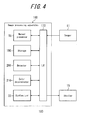
- a drive assisting apparatus 10 including an image processing apparatus according to a first embodiment will be described.
- a drive assisting apparatus 10 includes an imager 11, a brake sensor 12, a lamp switch 13, an ECU (Engine Control Unit) 14, a display 15, and an image processing apparatus 16.
- the imager 11 is installed so as to be able to image behind a vehicle.
- the imager 11 is fixed to an upper rear portion of the vehicle at a depression angle of about 30° so as to capture a subject in an area of approximately 8 meters behind the vehicle.
- the imager 11 includes an optical system and an image sensor and captures a subject image formed on the image sensor by the optical system.
- the image sensor includes a color filter array and is capable of capturing a color image.
- the imager 11 generates an image signal of the captured image thus captured and transmits the image signal to the image processing apparatus 16.
- the brake sensor 12 detects a depression amount of a brake pedal.
- the brake sensor 12 transmits the depression amount thus detected to the ECU 14.
- the lamp switch 13 detects a lighting-up input and a lighting-out input to head lamps of the vehicle. The lamp switch 13 transmits the input thus detected to the ECU 14.
- the ECU 14 obtains information and inputs detected by various sensors and switches provided to the vehicle and controls operations of the vehicle in a variety of manners. For example, based on an accelerator position detected by an accelerator sensor and temperature detected by temperature sensors provided at various portions of an engine, the ECU 14 adjusts a fuel feeding amount to the engine. Further, the ECU 14 adjusts a braking force based on a depression amount detected by the brake sensor 12 and also lights up brake lamps for emitting a first color light, e.g., red light. Further, based on the lighting-up input or the lighting-out input detected by the lamp switch 13, the ECU 14 light up or light out the head lamps.
- a first color light e.g., red light
- the ECU 14 notifies the image processing apparatus 16 of braking information indicating a braking state based on the depression amount detected by the brake sensor 12 and lighting information indicating that the head lamps are lit up based on the lighting-up input detected by the lamp switch 13.
- the display 15 is, for example, an LCD and disposed in the vicinity of a driver's seat.
- the display 15 may display the video in real time.
- the display 15, in order to display the video in real time obtains an image signal of one frame, for example, every 1/30 second from the image processing apparatus 16 and, by changing the image being displayed every 1/30 second, displays the video.
- the image processing apparatus 16 carries out predetermined image processing on the image signal generated by the imager 11 and transmits thus processed image signal to the display 15. As described above, the imager 11 generates the image signal of one frame every 1/30 second, and the image processing apparatus 16 obtains the image signal of one frame every 1/30 second. The image processing apparatus 16 processes the obtained image signal and transmits thus processed image signal to the display 15 every 1/30 second.
- the image processing apparatus 16 includes a drive assisting function for reverse travel, and may carry out image processing to display a drive assisting indicator on the video displayed in real time, so as to assist the reverse travel. Now, the display of the drive assisting indicator will be described together with a configuration of the image processing apparatus 16.
- the image processing apparatus 16 includes an I/F 17, a normal processor 18, a storage 19, a detector 20, a color determining unit 21, and a synthesizer 22.
- the I/F 17 is connected to the imager 11, the ECU 14, and the display 15 and thus capable of exchanging the information and the signal therewith.
- the I/F 17 receives the image signal from the imager 11, and also receives the braking information and the lighting information from the ECU 14.
- the I/F 17 transmits the image signal having been subjected to the image processing in the image processing apparatus 16 to the display 15.
- the I/F 17 is connected to the normal processor 18, the storage 19, the detector 20, the color determinator 21, and the synthesizer 22 and exchanges the information and the signal therewith.
- the normal processor 18 carries out, to the captured image obtained from the imager 11, normal image processing such as AGC, white balance, color interpolation, and gamma correction.
- the storage 19 stores data necessary for various control executed by the image processing apparatus 16.
- the storage 19 stores, for example, an outline and a position of the drive assisting indicator.
- the detector 20 based on the image signal obtained from the imager 11, detects color in the vicinity of a position where the drive assisting indicator is to be superimposed in the captured image.
- the detector 20 when obtaining the lighting information, i.e., when the head lamps are lit up, detects the color of the captured image.
- the color determinator 21 based on the lighting information, the braking information, and the color of the subject in the vicinity of the position where the drive assisting indicator is to be superimposed in the captured image, determines color of the drive assisting indicator.
- the color determinator 21 determines a first color, e.g., red as the color of the drive assisting indicator. When the head lamps are on, the color determinator 21 further determines whether the color in the vicinity of the position where the drive assisting indicator is to be superimposed in the captured image is similar to blue green.
- colors within a range of an angle of a° from blue green on both sides thereof in a color wheel are determined as colors similar to blue green.
- the color determinator 21 determines a second color, e.g., blue green as the color of the drive assisting indicator.
- the color determinator 21 determines a third color, e.g., yellow as the color of the drive assisting indicator.
- the synthesizer 22 superimposes the drive assisting indicator on the captured image having been subjected to the normal image processing.
- the synthesizer 22 colors the inside of the outline of the drive assisting indicator the color determined by the color determinator 21 and superimposes the drive assisting indicator thus colored at the position in the captured image retrieved from the storage 19.
- the drive assisting indicator 23 is made up of vehicle width extension lines 25 and reference distance lines 26.
- the vehicle extension lines 25 are trajectories on which either side of the vehicle passes during the reverse travel.
- the reference distance lines 26 indicate predetermined distances from the vehicle such as, for example, 1 meter and 3 meters.
- a driver by referring to the drive assisting indicator 23, may recognize a traveling direction during the reverse drive of the vehicle.
- the drive assisting processing starts when an input unit of the image processing apparatus 16 detects an input to start execution of the drive assisting function. Also, the drive assisting processing ends upon detection of an input to end the execution of the drive assisting function.
- step S100 the image processing apparatus 16 receives the image signal from the imager 11. After the reception of the image signal, the process proceeds to step S101.
- step S101 the image processing apparatus 16 determines whether the lighting information has been obtained. When the lighting information has been obtained, the image processing apparatus 16 determines that the head lamps are on, and the process proceeds to step S102. When the lighting information has not been obtained, the image processing apparatus 16 determines that the head lamps are off, and the process proceeds to step S103.
- step S102 the image processing apparatus 16 determines whether the braking information has been obtained. When the braking information has not been obtained, the image processing apparatus 16 determines that the brake lamps are off, and the process proceeds to step S103.
- step S103 the image processing apparatus 16 determines red as the color of the drive assisting indicator 23. After the determination of the color, the process proceeds to step S107.
- step S104 the image processing apparatus 16 determines whether the color in the vicinity of the position where the drive assisting indicator 23 is to be superimposed in the captured image 24 is similar to blue green. When the color in the vicinity of the position is not similar to blue green, the process proceeds to step S105. When the color in the vicinity of the position is similar to blue green, the process proceeds to step S106.
- step S105 the image processing apparatus 16 determines blue green as the color of the drive assisting indicator 23. After the determination of the color, the process proceeds to step S107.
- step S106 the image processing apparatus 16 determines yellow as the color of the drive assisting indicator 23. After the determination of the color, the process proceeds to step S107.
- step S107 the image processing apparatus 16 superimposes the drive assisting indicator 23 in color determined at any one of steps S103, S105, and S106 on the captured image 24. After the superimposition of the drive assisting indicator 23 on the captured image, the process proceeds to step S108.
- step S108 the image processing apparatus 16 transmits the captured image 24 including the drive assisting indicator 23 superimposed thereon to the display 15. After the transmission of the captured image 24, the process returns to step S100.
- the color of the drive assisting indicator 23 is changed, when the braking information is obtained, from the first color to the second color.
- the drive assisting indicator 23 is usually displayed in the first color (red), which is easily visible.
- the captured image 24 entirely has a tinge of red, making it difficult to view the drive assisting indicator 23 in red.
- the color of the captured image 24 becomes similar to the first color (red) and, in such a case, the color of the drive assisting indicator 23 is changed to the second color (blue green). Therefore, even when the color of the captured image 24 is similar to red, the drive assisting indicator 23 may be easily viewed.
- the color of the drive assisting indicator 23 is changed. It is considered that, when the head lamps are off, the vehicle is located outdoors at daytime where it is bright enough with the ambient light. In such a case, therefore, when the brake lamps are lit up, the color of the subject in the vicinity of the vehicle does not become similar to red, and thus the driver may view the drive assisting indicator 23 in red. On the other hand, it is considered that the head lamps are lit up at nighttime or when the vehicle is located indoors. In such a case, the red light of the brake lamps accounts for the majority of lights emitted to the subject in the vicinity of the vehicle. Accordingly, since the color of the drive assisting indicator 23 is changed only when it is considered to be at nighttime or when the vehicle is located indoors, an unnecessary change of the color may be prevented.
- the color of the drive assisting indicator 23 is changed to the third color (yellow).
- color of reflection light of the light emitted in the first color reflected on the subject in the vicinity of the drive assisting indicator 23 is similar to blue green, it may be difficult to view the drive assisting indicator 23 in blue green. In such a case, therefore, the color of the drive assisting indicator 23 is changed to the third color, allowing the driver to easily view the drive assisting indicator 23.
- the color of the drive assisting indicator 23 is changed based on the lighting information. Therefore, the color is changed without complex processing, allowing a reduction in time required for the change.
- the image processing apparatus 16 of the first embodiment further, when the color of the subject in the captured image 24 is similar to the first color (red), the color of the drive assisting indicator 23 is changed to the second color (blue green), which is complementary color of the first color (red). Therefore, the visibility of the drive assisting indicator 23 in the captured image 24 having a tinge of the first color may be improved.
- a trigger for changing the color of the drive assisting indicator is different from that of the first embodiment.
- the second embodiment will be described below, focusing on its differences from the first embodiment. Note that components having the same functions and configurations as those of the first embodiment are denoted by the same reference numerals.
- a drive assisting apparatus 100 includes the imager 11, the display 15, and an image processing apparatus 160. Unlike the first embodiment, the drive assisting apparatus 100 does not include the brake sensor, the lamp switch, and the ECU. Note that the configurations and functions of the imager 11 and the display 15 are respectively the same as those of the first embodiment.
- the image processing apparatus 160 carries out the predetermined image processing to the image signal generated by the imager 11 and transmits thus processed image signal to the display 15. Also, similarly to the first embodiment, the image processing apparatus 160 includes the drive assisting function and may carry out the image processing to display the drive assisting indicator on the video displayed in real time, so as to assist driving.
- the image processing apparatus 160 includes an I/F 170, the normal processor 18, a storage 190, a detector 200, a color determinator 210, and the synthesizer 22.
- the configurations and the functions of the normal processor 18 and the synthesizer 22 are respectively the same as those of the first embodiment.
- the I/F 170 is connected to the imager 11 and the display 15 and thus capable of exchanging the information and the signal therewith. Unlike the first embodiment, the I/F 170 is not connected to the ECU. Similarly to the first embodiment, on the other hand, the I/F 170 is connected to the normal processor 18, the storage 190, the detector 200, the color determinator 210, and the synthesizer 22 and exchanges the information and the signal therewith.
- the storage 190 similarly to the storage 19 of the first embodiment, stores the outline and the position of the drive assisting indicator 23. Unlike the first embodiment, the storage 190 preliminarily stores a plurality of combinations of colors of the drive assisting indicator 23 associated with the color of the captured image 24. The combinations are predetermined in such a manner that the color of the drive assisting indicator 23 serves as the complementary color of the color of the captured image 24.
- the detector 200 based on the image signal obtained from the imager 11, detects color of each pixel making up the captured image 24.
- the detector 200 based on hue of each pixel, determines whether the captured image 24 is entirely colored particular color.
- the detector 200 when the captured image 24 has a tinge of the particular color overall, detects the color of the captured image 24.
- the detector 200 after detecting the color of each pixel, classifies the detected hue into color with the most similar hue among predetermined plurality of colors.
- the predetermined plurality of colors are colors obtained by equally dividing the color wheel.
- the detector 200 creates a histogram having color with a highest degree among the classified colors at the center thereof.
- the detector 200 detects the number of samples classified into colors in a predetermined range having the color with the highest degree at the center thereof, and calculates a ratio thereof to a total number of samples. When thus calculated ratio exceeds a threshold, the determinator 200 determines that the captured image 24 has a tinge of the particular color overall and detects the color with the highest degree as the color of the captured image 24.
- the color determinator 210 determines the color of the drive assisting indicator 23.
- the color determinator 210 determines whether the detector 200 detects the particular color of the captured image 24.
- the color determinator 210 determines the first color, e.g., red as the color of the drive assisting indicator 23.
- the color determinator 210 determines the color of the drive assisting indicator 23 based on the particular color of the captured image 24.
- the color determinator 210 retrieves color of the drive assisting indicator 23 coupled to the particular color of the captured image 24 from the storage 190.
- the color determinator 210 determines thus retrieved color as the color of the drive assisting indicator 23.
- the drive assisting processing starts when an input unit of the image processing apparatus 160 detects an input to start execution of the drive assisting function. Also, the drive assisting processing ends upon detection of an input to end the execution of the drive assisting function.
- step S200 the image processing apparatus 160 receives the image signal from the imager 11. After the reception of the image signal, the process proceeds to step S201.
- step S201 the image processing apparatus 160 detects color of each pixel making up the captured image 24 corresponding to the image signal received at step S200. After the detection of the colors of the pixels, the process proceeds to step S202.
- step S202 the image processing apparatus 160 classifies the colors of the pixels detected at step S201 into colors in a predetermined color wheel. After the classification of the colors of all pixels of the captured image, the process proceeds to step S203.
- step S203 the image processing apparatus 160 determines the most frequent color among the classified colors, i.e., in sample pixels. After the determination of the most frequent color, the process proceeds to step S204.
- step S204 the image processing apparatus 160 creates the histogram of each of the colors having the color determined at step S203 at the center thereof. After the creation of the histogram, the process proceeds to step S205.
- the image processing apparatus 160 calculates the number of samples classified into the colors in the predetermined range from the most frequent color and calculates a ratio of the calculated number of samples to the total number of samples, i.e., pixels. After the calculation of the ratio, the process proceeds to step S206.
- step S206 the image processing apparatus 160 compares the ratio calculated at step S206 to the threshold. When the ratio exceeds the threshold, the process proceeds to step S207. When the ratio is no more than the threshold, the process proceeds to step S208.
- the image processing apparatus 160 determines the color determined at step S203 as the particular color of the captured image 24 and also determines the color preliminarily coupled to the particular color as the color of the drive assisting indicator 23. After the determination of the colors, the process proceeds to step S209.
- step S208 the image processing apparatus 160 determines red as the color of the drive assisting indicator 23. After the determination of the color, the process proceeds to step S209.
- step S209 the image processing apparatus 160 superimposes the drive assisting indicator 23 in the color determined at either one of steps S207 and S208 on the captured image 24. After the superimposition of the drive assisting indicator 23 on the captured image 24, the process proceeds to step S210.
- step S210 the image processing apparatus 160 transmits the captured image 24 including the drive assisting indicator 23 superimposed thereon to the display 15. After the transmission of the captured image, the process returns to step S200.
- the image processing apparatus 160 of the second embodiment having the configuration as described above also changes the color of the drive assisting indicator 23, when the captured image 24 has a tinge of the particular color overall, from the first color to the second color. Accordingly, when the captured image 24 is in color similar to the first color (red), the drive assisting indicator 23 may be easily viewed.
- the drive assisting indicator 23 is colored the complementary color of the particular color. Accordingly, the visibility of the drive assisting indicator 23 may be improved.
- the color of the drive assisting indicator 23 is changed to the complementary color of the color of the captured image 24
- the color of the drive assisting indicator 23 may be changed such that at least one of huc, brightness, and intensity of the drive assisting indicator 23 differs from those of the color of the captured image 24.
- the present invention is not limited to this manner. For example, assuming that it is at nighttime or the vehicle is located indoors based on an average value of the brightness of the entire captured image, the color of the drive assisting indicator 23 may be changed.
Landscapes
- Engineering & Computer Science (AREA)
- Physics & Mathematics (AREA)
- General Physics & Mathematics (AREA)
- Multimedia (AREA)
- Mechanical Engineering (AREA)
- Computer Hardware Design (AREA)
- Theoretical Computer Science (AREA)
- Closed-Circuit Television Systems (AREA)
- Image Analysis (AREA)
- Traffic Control Systems (AREA)
- Image Processing (AREA)
Applications Claiming Priority (2)
| Application Number | Priority Date | Filing Date | Title |
|---|---|---|---|
| JP2012097067A JP2013224081A (ja) | 2012-04-20 | 2012-04-20 | 画像処理装置および走行支援方法 |
| PCT/JP2013/002563 WO2013157250A1 (fr) | 2012-04-20 | 2013-04-16 | Dispositif de traitement d'image et procédé d'aide à la conduite |
Publications (3)
| Publication Number | Publication Date |
|---|---|
| EP2839991A1 true EP2839991A1 (fr) | 2015-02-25 |
| EP2839991A4 EP2839991A4 (fr) | 2016-04-06 |
| EP2839991B1 EP2839991B1 (fr) | 2019-10-09 |
Family
ID=49383221
Family Applications (1)
| Application Number | Title | Priority Date | Filing Date |
|---|---|---|---|
| EP13777578.9A Active EP2839991B1 (fr) | 2012-04-20 | 2013-04-16 | Dispositif de traitement d'image et procédé d'aide à la conduite |
Country Status (4)
| Country | Link |
|---|---|
| US (1) | US9789818B2 (fr) |
| EP (1) | EP2839991B1 (fr) |
| JP (1) | JP2013224081A (fr) |
| WO (1) | WO2013157250A1 (fr) |
Families Citing this family (3)
| Publication number | Priority date | Publication date | Assignee | Title |
|---|---|---|---|---|
| US9762895B1 (en) * | 2014-03-11 | 2017-09-12 | Rockwell Collins, Inc. | Dual simultaneous image presentation for a three-dimensional aviation display |
| KR101627500B1 (ko) | 2014-10-31 | 2016-06-07 | 현대모비스 주식회사 | 차량 보조 장치 및 그 동작 방법 |
| JP7129270B2 (ja) * | 2018-08-13 | 2022-09-01 | Kyb株式会社 | 画像処理装置、画像処理方法及び画像処理システム |
Family Cites Families (15)
| Publication number | Priority date | Publication date | Assignee | Title |
|---|---|---|---|---|
| JP3485165B2 (ja) * | 1999-03-30 | 2004-01-13 | 矢崎総業株式会社 | 車両用バックモニタ装置 |
| US7366595B1 (en) | 1999-06-25 | 2008-04-29 | Seiko Epson Corporation | Vehicle drive assist system |
| JP2002362270A (ja) * | 2001-06-11 | 2002-12-18 | Matsushita Electric Ind Co Ltd | 運転支援装置 |
| JP4882285B2 (ja) | 2005-06-15 | 2012-02-22 | 株式会社デンソー | 車両用走行支援装置 |
| JP2008137425A (ja) * | 2006-11-30 | 2008-06-19 | Aisin Aw Co Ltd | 駐車支援方法及び駐車支援装置 |
| JP4623393B2 (ja) | 2008-05-08 | 2011-02-02 | アイシン精機株式会社 | 車両周辺表示装置 |
| JP5636609B2 (ja) * | 2008-05-08 | 2014-12-10 | アイシン精機株式会社 | 車両周辺表示装置 |
| JP5178361B2 (ja) * | 2008-07-09 | 2013-04-10 | 本田技研工業株式会社 | 運転支援装置 |
| JP2010128794A (ja) * | 2008-11-27 | 2010-06-10 | Aisin Seiki Co Ltd | 車両周辺認知支援装置 |
| JPWO2011013813A1 (ja) | 2009-07-30 | 2013-01-10 | クラリオン株式会社 | 車載装置および画像処理プログラム |
| JP5212748B2 (ja) * | 2010-09-29 | 2013-06-19 | アイシン精機株式会社 | 駐車支援装置 |
| US9357180B2 (en) * | 2011-01-27 | 2016-05-31 | Kyocera Corporation | Vehicle driving assist device |
| US9363485B2 (en) * | 2011-01-27 | 2016-06-07 | Kyocera Corporation | Vehicle driving assist device |
| KR101295092B1 (ko) * | 2011-12-28 | 2013-08-09 | 현대자동차주식회사 | 차량용 색상검출기 |
| JP5960466B2 (ja) * | 2012-03-28 | 2016-08-02 | 京セラ株式会社 | 画像処理装置、撮像装置、車両の運転支援装置、及び画像処理方法 |
-
2012
- 2012-04-20 JP JP2012097067A patent/JP2013224081A/ja active Pending
-
2013
- 2013-04-16 EP EP13777578.9A patent/EP2839991B1/fr active Active
- 2013-04-16 US US14/395,601 patent/US9789818B2/en active Active
- 2013-04-16 WO PCT/JP2013/002563 patent/WO2013157250A1/fr active Application Filing
Also Published As
| Publication number | Publication date |
|---|---|
| WO2013157250A1 (fr) | 2013-10-24 |
| EP2839991A4 (fr) | 2016-04-06 |
| EP2839991B1 (fr) | 2019-10-09 |
| US9789818B2 (en) | 2017-10-17 |
| JP2013224081A (ja) | 2013-10-31 |
| US20150070486A1 (en) | 2015-03-12 |
Similar Documents
| Publication | Publication Date | Title |
|---|---|---|
| EP2448251B1 (fr) | Regroupement de systèmes d'assistance au conducteur en vision nocturne et autres utilisant un éclairage à infrarouge proche et un obturateur roulant. | |
| JP5846872B2 (ja) | 画像処理装置 | |
| US9626570B2 (en) | Vehicle control system and image sensor | |
| JP5299026B2 (ja) | 車両用表示装置 | |
| JP2007164636A (ja) | 道路区画線検出装置 | |
| US20130088598A1 (en) | Obstacle detection system and method, and obstacle detection apparatus | |
| JP2009043068A (ja) | 信号機認識装置 | |
| JP2015149614A (ja) | 画像解析装置、および画像解析方法 | |
| KR102637216B1 (ko) | 차량용 신호등 단계를 감지하기 위한 장치 및 방법 | |
| EP2839991B1 (fr) | Dispositif de traitement d'image et procédé d'aide à la conduite | |
| JP2013235444A (ja) | 車両視界支援装置 | |
| JP2015097018A (ja) | 矢印信号灯検出装置 | |
| KR101784629B1 (ko) | 카메라를 이용한 차량의 램프 고장진단방법 | |
| JP6204022B2 (ja) | 画像処理装置、撮像装置および画像処理方法 | |
| JP2008026991A (ja) | 信号機識別装置 | |
| JP5686042B2 (ja) | 車両周辺表示装置 | |
| KR20140030726A (ko) | 안개 상황에서의 차량 추돌 방지 장치 | |
| KR101850030B1 (ko) | 조도를 이용한 차선 변경 보조 방법 및 장치 | |
| JP6227874B2 (ja) | 画像処理装置および走行支援方法 | |
| US20150353013A1 (en) | Detection apparatus | |
| EP3637368B1 (fr) | Dispositif de traitement d'image et système de commande de distribution de lumière | |
| KR101822302B1 (ko) | 차량의 헤드램프 제어 장치 및 이의 구동 방법 | |
| KR20110128661A (ko) | 자동차의 차량 검출방법 | |
| KR20100033715A (ko) | 측방 카메라의 야간 촬영 조건을 개선하는 방법 |
Legal Events
| Date | Code | Title | Description |
|---|---|---|---|
| PUAI | Public reference made under article 153(3) epc to a published international application that has entered the european phase |
Free format text: ORIGINAL CODE: 0009012 |
|
| 17P | Request for examination filed |
Effective date: 20141020 |
|
| AK | Designated contracting states |
Kind code of ref document: A1 Designated state(s): AL AT BE BG CH CY CZ DE DK EE ES FI FR GB GR HR HU IE IS IT LI LT LU LV MC MK MT NL NO PL PT RO RS SE SI SK SM TR |
|
| AX | Request for extension of the european patent |
Extension state: BA ME |
|
| DAX | Request for extension of the european patent (deleted) | ||
| RA4 | Supplementary search report drawn up and despatched (corrected) |
Effective date: 20160303 |
|
| RIC1 | Information provided on ipc code assigned before grant |
Ipc: B60R 21/00 20060101ALI20160226BHEP Ipc: H04N 7/18 20060101ALI20160226BHEP Ipc: G08G 1/0962 20060101ALI20160226BHEP Ipc: B60R 1/00 20060101AFI20160226BHEP Ipc: G08G 1/16 20060101ALI20160226BHEP |
|
| STAA | Information on the status of an ep patent application or granted ep patent |
Free format text: STATUS: EXAMINATION IS IN PROGRESS |
|
| 17Q | First examination report despatched |
Effective date: 20170526 |
|
| GRAP | Despatch of communication of intention to grant a patent |
Free format text: ORIGINAL CODE: EPIDOSNIGR1 |
|
| STAA | Information on the status of an ep patent application or granted ep patent |
Free format text: STATUS: GRANT OF PATENT IS INTENDED |
|
| INTG | Intention to grant announced |
Effective date: 20190514 |
|
| GRAS | Grant fee paid |
Free format text: ORIGINAL CODE: EPIDOSNIGR3 |
|
| GRAA | (expected) grant |
Free format text: ORIGINAL CODE: 0009210 |
|
| STAA | Information on the status of an ep patent application or granted ep patent |
Free format text: STATUS: THE PATENT HAS BEEN GRANTED |
|
| AK | Designated contracting states |
Kind code of ref document: B1 Designated state(s): AL AT BE BG CH CY CZ DE DK EE ES FI FR GB GR HR HU IE IS IT LI LT LU LV MC MK MT NL NO PL PT RO RS SE SI SK SM TR |
|
| REG | Reference to a national code |
Ref country code: GB Ref legal event code: FG4D |
|
| REG | Reference to a national code |
Ref country code: CH Ref legal event code: EP |
|
| REG | Reference to a national code |
Ref country code: IE Ref legal event code: FG4D |
|
| REG | Reference to a national code |
Ref country code: DE Ref legal event code: R096 Ref document number: 602013061505 Country of ref document: DE |
|
| REG | Reference to a national code |
Ref country code: AT Ref legal event code: REF Ref document number: 1188419 Country of ref document: AT Kind code of ref document: T Effective date: 20191115 |
|
| REG | Reference to a national code |
Ref country code: NL Ref legal event code: MP Effective date: 20191009 |
|
| REG | Reference to a national code |
Ref country code: LT Ref legal event code: MG4D |
|
| REG | Reference to a national code |
Ref country code: AT Ref legal event code: MK05 Ref document number: 1188419 Country of ref document: AT Kind code of ref document: T Effective date: 20191009 |
|
| PG25 | Lapsed in a contracting state [announced via postgrant information from national office to epo] |
Ref country code: BG Free format text: LAPSE BECAUSE OF FAILURE TO SUBMIT A TRANSLATION OF THE DESCRIPTION OR TO PAY THE FEE WITHIN THE PRESCRIBED TIME-LIMIT Effective date: 20200109 Ref country code: NO Free format text: LAPSE BECAUSE OF FAILURE TO SUBMIT A TRANSLATION OF THE DESCRIPTION OR TO PAY THE FEE WITHIN THE PRESCRIBED TIME-LIMIT Effective date: 20200109 Ref country code: FI Free format text: LAPSE BECAUSE OF FAILURE TO SUBMIT A TRANSLATION OF THE DESCRIPTION OR TO PAY THE FEE WITHIN THE PRESCRIBED TIME-LIMIT Effective date: 20191009 Ref country code: LT Free format text: LAPSE BECAUSE OF FAILURE TO SUBMIT A TRANSLATION OF THE DESCRIPTION OR TO PAY THE FEE WITHIN THE PRESCRIBED TIME-LIMIT Effective date: 20191009 Ref country code: PL Free format text: LAPSE BECAUSE OF FAILURE TO SUBMIT A TRANSLATION OF THE DESCRIPTION OR TO PAY THE FEE WITHIN THE PRESCRIBED TIME-LIMIT Effective date: 20191009 Ref country code: PT Free format text: LAPSE BECAUSE OF FAILURE TO SUBMIT A TRANSLATION OF THE DESCRIPTION OR TO PAY THE FEE WITHIN THE PRESCRIBED TIME-LIMIT Effective date: 20200210 Ref country code: ES Free format text: LAPSE BECAUSE OF FAILURE TO SUBMIT A TRANSLATION OF THE DESCRIPTION OR TO PAY THE FEE WITHIN THE PRESCRIBED TIME-LIMIT Effective date: 20191009 Ref country code: LV Free format text: LAPSE BECAUSE OF FAILURE TO SUBMIT A TRANSLATION OF THE DESCRIPTION OR TO PAY THE FEE WITHIN THE PRESCRIBED TIME-LIMIT Effective date: 20191009 Ref country code: NL Free format text: LAPSE BECAUSE OF FAILURE TO SUBMIT A TRANSLATION OF THE DESCRIPTION OR TO PAY THE FEE WITHIN THE PRESCRIBED TIME-LIMIT Effective date: 20191009 Ref country code: SE Free format text: LAPSE BECAUSE OF FAILURE TO SUBMIT A TRANSLATION OF THE DESCRIPTION OR TO PAY THE FEE WITHIN THE PRESCRIBED TIME-LIMIT Effective date: 20191009 Ref country code: AT Free format text: LAPSE BECAUSE OF FAILURE TO SUBMIT A TRANSLATION OF THE DESCRIPTION OR TO PAY THE FEE WITHIN THE PRESCRIBED TIME-LIMIT Effective date: 20191009 Ref country code: GR Free format text: LAPSE BECAUSE OF FAILURE TO SUBMIT A TRANSLATION OF THE DESCRIPTION OR TO PAY THE FEE WITHIN THE PRESCRIBED TIME-LIMIT Effective date: 20200110 |
|
| PG25 | Lapsed in a contracting state [announced via postgrant information from national office to epo] |
Ref country code: IS Free format text: LAPSE BECAUSE OF FAILURE TO SUBMIT A TRANSLATION OF THE DESCRIPTION OR TO PAY THE FEE WITHIN THE PRESCRIBED TIME-LIMIT Effective date: 20200224 Ref country code: RS Free format text: LAPSE BECAUSE OF FAILURE TO SUBMIT A TRANSLATION OF THE DESCRIPTION OR TO PAY THE FEE WITHIN THE PRESCRIBED TIME-LIMIT Effective date: 20191009 Ref country code: HR Free format text: LAPSE BECAUSE OF FAILURE TO SUBMIT A TRANSLATION OF THE DESCRIPTION OR TO PAY THE FEE WITHIN THE PRESCRIBED TIME-LIMIT Effective date: 20191009 |
|
| PG25 | Lapsed in a contracting state [announced via postgrant information from national office to epo] |
Ref country code: AL Free format text: LAPSE BECAUSE OF FAILURE TO SUBMIT A TRANSLATION OF THE DESCRIPTION OR TO PAY THE FEE WITHIN THE PRESCRIBED TIME-LIMIT Effective date: 20191009 |
|
| REG | Reference to a national code |
Ref country code: DE Ref legal event code: R097 Ref document number: 602013061505 Country of ref document: DE |
|
| PG2D | Information on lapse in contracting state deleted |
Ref country code: IS |
|
| PG25 | Lapsed in a contracting state [announced via postgrant information from national office to epo] |
Ref country code: EE Free format text: LAPSE BECAUSE OF FAILURE TO SUBMIT A TRANSLATION OF THE DESCRIPTION OR TO PAY THE FEE WITHIN THE PRESCRIBED TIME-LIMIT Effective date: 20191009 Ref country code: DK Free format text: LAPSE BECAUSE OF FAILURE TO SUBMIT A TRANSLATION OF THE DESCRIPTION OR TO PAY THE FEE WITHIN THE PRESCRIBED TIME-LIMIT Effective date: 20191009 Ref country code: RO Free format text: LAPSE BECAUSE OF FAILURE TO SUBMIT A TRANSLATION OF THE DESCRIPTION OR TO PAY THE FEE WITHIN THE PRESCRIBED TIME-LIMIT Effective date: 20191009 Ref country code: CZ Free format text: LAPSE BECAUSE OF FAILURE TO SUBMIT A TRANSLATION OF THE DESCRIPTION OR TO PAY THE FEE WITHIN THE PRESCRIBED TIME-LIMIT Effective date: 20191009 Ref country code: IS Free format text: LAPSE BECAUSE OF FAILURE TO SUBMIT A TRANSLATION OF THE DESCRIPTION OR TO PAY THE FEE WITHIN THE PRESCRIBED TIME-LIMIT Effective date: 20200209 |
|
| PLBE | No opposition filed within time limit |
Free format text: ORIGINAL CODE: 0009261 |
|
| STAA | Information on the status of an ep patent application or granted ep patent |
Free format text: STATUS: NO OPPOSITION FILED WITHIN TIME LIMIT |
|
| PG25 | Lapsed in a contracting state [announced via postgrant information from national office to epo] |
Ref country code: IT Free format text: LAPSE BECAUSE OF FAILURE TO SUBMIT A TRANSLATION OF THE DESCRIPTION OR TO PAY THE FEE WITHIN THE PRESCRIBED TIME-LIMIT Effective date: 20191009 Ref country code: SM Free format text: LAPSE BECAUSE OF FAILURE TO SUBMIT A TRANSLATION OF THE DESCRIPTION OR TO PAY THE FEE WITHIN THE PRESCRIBED TIME-LIMIT Effective date: 20191009 Ref country code: SK Free format text: LAPSE BECAUSE OF FAILURE TO SUBMIT A TRANSLATION OF THE DESCRIPTION OR TO PAY THE FEE WITHIN THE PRESCRIBED TIME-LIMIT Effective date: 20191009 |
|
| 26N | No opposition filed |
Effective date: 20200710 |
|
| PG25 | Lapsed in a contracting state [announced via postgrant information from national office to epo] |
Ref country code: MC Free format text: LAPSE BECAUSE OF FAILURE TO SUBMIT A TRANSLATION OF THE DESCRIPTION OR TO PAY THE FEE WITHIN THE PRESCRIBED TIME-LIMIT Effective date: 20191009 Ref country code: SI Free format text: LAPSE BECAUSE OF FAILURE TO SUBMIT A TRANSLATION OF THE DESCRIPTION OR TO PAY THE FEE WITHIN THE PRESCRIBED TIME-LIMIT Effective date: 20191009 |
|
| REG | Reference to a national code |
Ref country code: CH Ref legal event code: PL |
|
| PG25 | Lapsed in a contracting state [announced via postgrant information from national office to epo] |
Ref country code: LI Free format text: LAPSE BECAUSE OF NON-PAYMENT OF DUE FEES Effective date: 20200430 Ref country code: CH Free format text: LAPSE BECAUSE OF NON-PAYMENT OF DUE FEES Effective date: 20200430 Ref country code: LU Free format text: LAPSE BECAUSE OF NON-PAYMENT OF DUE FEES Effective date: 20200416 |
|
| REG | Reference to a national code |
Ref country code: BE Ref legal event code: MM Effective date: 20200430 |
|
| PG25 | Lapsed in a contracting state [announced via postgrant information from national office to epo] |
Ref country code: BE Free format text: LAPSE BECAUSE OF NON-PAYMENT OF DUE FEES Effective date: 20200430 |
|
| PG25 | Lapsed in a contracting state [announced via postgrant information from national office to epo] |
Ref country code: IE Free format text: LAPSE BECAUSE OF NON-PAYMENT OF DUE FEES Effective date: 20200416 |
|
| PG25 | Lapsed in a contracting state [announced via postgrant information from national office to epo] |
Ref country code: TR Free format text: LAPSE BECAUSE OF FAILURE TO SUBMIT A TRANSLATION OF THE DESCRIPTION OR TO PAY THE FEE WITHIN THE PRESCRIBED TIME-LIMIT Effective date: 20191009 Ref country code: MT Free format text: LAPSE BECAUSE OF FAILURE TO SUBMIT A TRANSLATION OF THE DESCRIPTION OR TO PAY THE FEE WITHIN THE PRESCRIBED TIME-LIMIT Effective date: 20191009 Ref country code: CY Free format text: LAPSE BECAUSE OF FAILURE TO SUBMIT A TRANSLATION OF THE DESCRIPTION OR TO PAY THE FEE WITHIN THE PRESCRIBED TIME-LIMIT Effective date: 20191009 |
|
| PG25 | Lapsed in a contracting state [announced via postgrant information from national office to epo] |
Ref country code: MK Free format text: LAPSE BECAUSE OF FAILURE TO SUBMIT A TRANSLATION OF THE DESCRIPTION OR TO PAY THE FEE WITHIN THE PRESCRIBED TIME-LIMIT Effective date: 20191009 |
|
| PGFP | Annual fee paid to national office [announced via postgrant information from national office to epo] |
Ref country code: FR Payment date: 20230309 Year of fee payment: 11 |
|
| P01 | Opt-out of the competence of the unified patent court (upc) registered |
Effective date: 20230505 |
|
| PGFP | Annual fee paid to national office [announced via postgrant information from national office to epo] |
Ref country code: DE Payment date: 20230228 Year of fee payment: 11 |
|
| PGFP | Annual fee paid to national office [announced via postgrant information from national office to epo] |
Ref country code: GB Payment date: 20240229 Year of fee payment: 12 |