EP2839247B1 - Magnetischer kodierer zur produktion eines indexsignals - Google Patents
Magnetischer kodierer zur produktion eines indexsignals Download PDFInfo
- Publication number
- EP2839247B1 EP2839247B1 EP13711809.7A EP13711809A EP2839247B1 EP 2839247 B1 EP2839247 B1 EP 2839247B1 EP 13711809 A EP13711809 A EP 13711809A EP 2839247 B1 EP2839247 B1 EP 2839247B1
- Authority
- EP
- European Patent Office
- Prior art keywords
- pole
- north
- track
- south
- junction
- Prior art date
- Legal status (The legal status is an assumption and is not a legal conclusion. Google has not performed a legal analysis and makes no representation as to the accuracy of the status listed.)
- Active
Links
- 238000001514 detection method Methods 0.000 description 2
- 239000007788 liquid Substances 0.000 description 2
- 239000000463 material Substances 0.000 description 2
- 238000002485 combustion reaction Methods 0.000 description 1
- 238000010276 construction Methods 0.000 description 1
- 239000000446 fuel Substances 0.000 description 1
- 238000002347 injection Methods 0.000 description 1
- 239000007924 injection Substances 0.000 description 1
- 238000004519 manufacturing process Methods 0.000 description 1
- 238000000034 method Methods 0.000 description 1
- 238000012986 modification Methods 0.000 description 1
- 230000004048 modification Effects 0.000 description 1
- 230000001360 synchronised effect Effects 0.000 description 1
Images


Classifications
-
- G—PHYSICS
- G01—MEASURING; TESTING
- G01D—MEASURING NOT SPECIALLY ADAPTED FOR A SPECIFIC VARIABLE; ARRANGEMENTS FOR MEASURING TWO OR MORE VARIABLES NOT COVERED IN A SINGLE OTHER SUBCLASS; TARIFF METERING APPARATUS; MEASURING OR TESTING NOT OTHERWISE PROVIDED FOR
- G01D5/00—Mechanical means for transferring the output of a sensing member; Means for converting the output of a sensing member to another variable where the form or nature of the sensing member does not constrain the means for converting; Transducers not specially adapted for a specific variable
- G01D5/12—Mechanical means for transferring the output of a sensing member; Means for converting the output of a sensing member to another variable where the form or nature of the sensing member does not constrain the means for converting; Transducers not specially adapted for a specific variable using electric or magnetic means
- G01D5/244—Mechanical means for transferring the output of a sensing member; Means for converting the output of a sensing member to another variable where the form or nature of the sensing member does not constrain the means for converting; Transducers not specially adapted for a specific variable using electric or magnetic means influencing characteristics of pulses or pulse trains; generating pulses or pulse trains
- G01D5/245—Mechanical means for transferring the output of a sensing member; Means for converting the output of a sensing member to another variable where the form or nature of the sensing member does not constrain the means for converting; Transducers not specially adapted for a specific variable using electric or magnetic means influencing characteristics of pulses or pulse trains; generating pulses or pulse trains using a variable number of pulses in a train
-
- G—PHYSICS
- G01—MEASURING; TESTING
- G01D—MEASURING NOT SPECIALLY ADAPTED FOR A SPECIFIC VARIABLE; ARRANGEMENTS FOR MEASURING TWO OR MORE VARIABLES NOT COVERED IN A SINGLE OTHER SUBCLASS; TARIFF METERING APPARATUS; MEASURING OR TESTING NOT OTHERWISE PROVIDED FOR
- G01D5/00—Mechanical means for transferring the output of a sensing member; Means for converting the output of a sensing member to another variable where the form or nature of the sensing member does not constrain the means for converting; Transducers not specially adapted for a specific variable
- G01D5/12—Mechanical means for transferring the output of a sensing member; Means for converting the output of a sensing member to another variable where the form or nature of the sensing member does not constrain the means for converting; Transducers not specially adapted for a specific variable using electric or magnetic means
- G01D5/244—Mechanical means for transferring the output of a sensing member; Means for converting the output of a sensing member to another variable where the form or nature of the sensing member does not constrain the means for converting; Transducers not specially adapted for a specific variable using electric or magnetic means influencing characteristics of pulses or pulse trains; generating pulses or pulse trains
- G01D5/245—Mechanical means for transferring the output of a sensing member; Means for converting the output of a sensing member to another variable where the form or nature of the sensing member does not constrain the means for converting; Transducers not specially adapted for a specific variable using electric or magnetic means influencing characteristics of pulses or pulse trains; generating pulses or pulse trains using a variable number of pulses in a train
- G01D5/2454—Encoders incorporating incremental and absolute signals
- G01D5/2455—Encoders incorporating incremental and absolute signals with incremental and absolute tracks on the same encoder
- G01D5/2457—Incremental encoders having reference marks
-
- H—ELECTRICITY
- H03—ELECTRONIC CIRCUITRY
- H03M—CODING; DECODING; CODE CONVERSION IN GENERAL
- H03M1/00—Analogue/digital conversion; Digital/analogue conversion
- H03M1/12—Analogue/digital converters
- H03M1/22—Analogue/digital converters pattern-reading type
- H03M1/24—Analogue/digital converters pattern-reading type using relatively movable reader and disc or strip
- H03M1/28—Analogue/digital converters pattern-reading type using relatively movable reader and disc or strip with non-weighted coding
- H03M1/30—Analogue/digital converters pattern-reading type using relatively movable reader and disc or strip with non-weighted coding incremental
- H03M1/308—Analogue/digital converters pattern-reading type using relatively movable reader and disc or strip with non-weighted coding incremental with additional pattern means for determining the absolute position, e.g. reference marks
Definitions
- the present invention relates to magnetic encoders, and more particularly to magnetic encoders for producing an index signal.
- US 4713613 discloses a magnetic encoder in which magnetic pole junctions on adjacent tracks are aligned with one another to prevent magnetic leakage between the tracks.
- US 2011/291646 discloses a magnetic encoder designed to operate with greater stability to determine an origin position in varying temperature conditions.
- the encoder utilizes an arrangement of side magnetized portions on both sides of the origin position magnetized portion.
- US 5965825 discloses a magnetic pulse encoder for fitting to a meter of a liquid dispenser device to supply a signal representative of the flow of dispensed liquid.
- EP 0443938 discloses a sensor for use on internal combustion engines to transmit signals indicative of ignition and fuel injection timing based on the position of magnetic encoders. Symmetric and asymmetric encoders are mounted on a support plate for synchronous rotation with the engine.
- US 2009/091316 discloses a magnetic encoder comprising a high resolution track including a plurality of North/South pole pairs defining a plurality of pole junctions; and a reference track including at least one North/South pole pair, wherein the encoder detects signals at a number of position indicator locations corresponding to pole junctions of the high resolution track.
- a magnetic encoder comprising a high resolution track including a plurality of North/South pole pairs defining a plurality of pole junctions; and a reference track including at least one North/South pole pair, wherein the encoder detects signals at a number of position indicator locations corresponding to pole junctions of the high resolution track; characterized in that one of the poles of the at least one North/South pole pair of the reference track has a shorter length than the other; and the length of the shorter pole of the at least one North/South pole pair of the reference track is sized to encompass only a single one of the position indicator locations to thereby define an index pulse.
- the following specification also discloses a magnetic encoder with a high resolution track including a plurality of North/South pole pairs defining a plurality of pole junctions, and a reference track including a North/South pole pair defining a North/South pole junction aligned with a first pole junction of the high resolution track, and a South/North pole junction aligned with a second pole junction of the high resolution track. Only a single pole junction of the high resolution track is positioned between the first and second pole junctions of the high resolution track.
- the following specification also discloses a magnetic encoder having a high resolution track including a plurality of North/South pole pairs defining a plurality of pole junctions, and a reference track including a North/South pole pair defining a North/South pole junction and a South/North pole junction.
- the plurality of pole junctions of the high resolution track includes consecutive first, second, and third pole junctions. The first pole junction is aligned with the North/South pole junction of the reference track, the third pole junction is aligned with the South/North pole junction of the reference track, and the second pole junction is between the first and third pole junctions.
- Fig. 1 illustrates a magnetic encoder 10 of the present invention.
- the encoder 10 includes a high resolution track 14 including a plurality of North/South pole pairs 18.
- the pole pairs 18 define a plurality of pole junctions, including North/South pole junctions 22 and South/North pole junctions 26.
- the pole pairs 18 are all the same size, but this need not be the case.
- the number of pole pairs 18 and resulting pole junctions 22, 26 can vary from that shown in Fig. 1 .
- the illustrated encoder 10 further includes a reference track 30 fixed relative to the high resolution track 14 and including only a single North/South pole pair 34 defining a single North/South pole junction 38 and a single South/North pole junction 42.
- the pole pair 34 includes a shorter pole and a longer pole.
- the shorter pole of the single North/South pole pair 34 (the South pole in the illustrated embodiment) has an angular span that is equal to the angular span of one of the North/South pole pairs 18 of the high resolution track 14 (e.g., 14.4 degrees in the illustrated embodiment).
- the phrase "angular span,” as used herein and in the appended claims refers to the angular length or length dimension of the referenced pole or pole pair as measured relative to the center point C.
- the North pole could be the shorter pole of the pole pair 34 and the South pole could have the longer length.
- the reference track 30 is illustrated as being radially inside the high resolution track 14, it is to be understood that the reference track 30 could alternatively be positioned radially outside of the high resolution track 14.
- the high resolution track 14 and the reference track 30 are illustrated as being formed as concentric circles, in other embodiments, the tracks 14, 30 could be formed as linear tracks arranged parallel to one another (see Fig. 3 - like parts have been given like reference numbers plus the prime (') symbol).
- the pole pair 34' is embodied as a South pole embedded in a larger North pole such that there will be one pole (the South pole in Fig. 3 ) surrounded by the other pole (the North pole on both sides of the South pole in Fig. 3 ).
- the tracks 14, 30 of the encoder 10, while illustrated as being completely separate from one another, are typically formed on a single piece of magnetizable material.
- the separate tracks 14, 30 are created using tooling and known techniques to magnetize the material to form the tracks 14, 30.
- the encoder 10 further includes a sensor chip 50 positioned over and spaced from the tracks 14, 30.
- a high resolution sensor 54 which can take the form of a string or array of sensors (e.g., Hall sensors), is positioned over the high resolution track 14.
- a reference sensor 58 which can take the form of a string or array of sensors (e.g., Hall sensors), is positioned over the reference track 30.
- the encoder 10 outputs signals (see Fig. 2 ) based on relative movement between the sensor chip 50 and the tracks 14, 30 (e.g., rotation for the concentric-track encoder 10, or translation for a linear-track encoder 10').
- the track configurations of the invention provide for the generation of an index signal or pulse that indicates a reference or index position of the tracks 14, 30.
- the single index position could be indicative of a desired angular position, such as top-dead-center, bottom-dead-center, or another significant position.
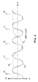
- Figure 2 is a graphical representation of the signals generated by the encoder 10.
- the horizontal axis represents angular position ⁇ of the tracks 14, 30, while the vertical axis represents a voltage V associated with each of the sensors 54, 58 on the chip 50.
- the line 62 represents the signal from the high resolution track 14 (as detected by the high resolution sensor 54), while the line 66 represents the signal from the reference track 30 (as detected by the reference sensor 58).
- Figs. 1 and 2 have been labeled with corresponding position indicators P1, P2, P3, P4, and P5 to facilitate correlation of the track positions to the generated signals.
- the voltage changes from positive to negative at each North/South pole junction 22, and changes from negative to positive at each South/North pole junction 26.
- a South pole generates a negative voltage reading
- a North pole generates a positive voltage reading.
- the positive and negative voltages associated with the polarities can be reversed.
- the signal 66 generated by the reference track 30 it can be seen that the voltage changes from positive to negative at the North/South pole junction 38, and changes from negative to positive at the South/North pole junction 42.
- the sensors 54, 58 detect voltages or voltage crossovers at each South/North pole junction 26 (at each position indicator P1, P2, P3, P4, P5, etc.) along the high resolution track 14, and detect an index signal or pulse at position indicator P3, because this location is the only position indicator location over the entire 360 degrees of rotation in which the voltage of the reference signal 66 is less than the voltage of the high resolution signal 62.
- the position indicators could be located at each pole junction (22 and 26) instead of only at every other pole junction (22 or 26).
- the sensor chip 50 compares the voltage values of the high resolution signal 62 and the reference signal 66 at each position indicator or South/North pole junction 26 of the high resolution signal 62 to discern when the index pulse is generated.
- the index signal could be the only position over the entire 360 degrees of rotation in which the voltage of the reference signal 66 is more than the voltage of the high resolution signal 62.
- the signal 66 from the reference track creates a single outlier or anomaly in relation to the signal 62 from the high resolution track 14 that can be detected by the circuitry as the index signal or pulse.
- the high resolution track 14, at each North/South pole junction 22 between the position indicators P1, P2, P3, P4, and P5, correlates to a voltage crossover point from positive to negative.
- the position indicators P1, P2, P4, and P5 are all within the angular span of the North pole of the reference track 30, correlating to a positive voltage value for the reference signal 66. Only the position indicator P3 is within the single South pole of the reference track 30, correlating to a negative voltage value for the reference signal 66. Only at position P3 is the value of the reference signal 66 less than the zero value at the voltage crossover of the high resolution signal 62. Therefore, the chip 50 generates an index signal or pulse at a location relative to the tracks 14, 30 coinciding with the position indicator P3.
- high resolution track 14 includes first, second, and third consecutive pole junctions designated as 82, 84, and 86, respectively (the pole junctions 82, 84, and 86 are three of the plurality of pole junctions 22, 26 of the high resolution track 14).
- the first pole junction 82 is aligned with the North/South pole junction 38 of the reference track 30, the third pole junction 86 is aligned with the South/North pole junction 42 of the reference track 30, and the second pole junction 84 is between the first and third pole junctions 82, 86.
- the term “aligned” means that the reference pole junctions are at the same angular position relative to the center point C for the illustrated concentric track arrangement.
- the term “aligned” means that the referenced pole junctions are co-linear with one another. This relationship would also hold true if the North pole of the reference track 30 were the shorter pole.
- the single North/South pole junction 38 of the reference track 30 is aligned with a first pole junction 82 of the plurality of pole junctions 22, 26 of the high resolution track 14, and the single South/North pole junction 42 of the reference track 30 is aligned with a second pole junction 86 of the plurality of pole junctions 22, 26 of the high resolution track 14.
- Only a single pole junction 84 of the high resolution track 14 is positioned between the pole junctions 82 and 86 of the plurality of pole junctions 22, 26 of the high resolution track 14. All three pole junctions 82, 84, and 86 are therefore aligned with the shorter pole of the reference track 14 (i.e., the South pole in the illustrated embodiment).
- a single pole junction 84 of the high resolution track 14 is positioned completely within the angular span between the North/South pole junction 38 and the South/North pole junction 42 of the reference track 30. There are no other pole junctions of the high resolution track 14 positioned within the angular span defined by the South pole (i.e., the shorter pole) of the single pole pair 34 of the reference track 30.
- the single pole junction 84 coincides with position indicator P3 and defines the index pulse.
- the illustrated encoder 10 of the present invention provides an index pulse that is twice as wide (i.e., has twice the wavelength) as index pulses created in prior art encoders.
- the wider index pulse created by the encoder 10 means that a larger air gap can be used between the sensors 54, 58 and the tracks 14, 30. This is because the larger index pulse produces a magnetic field that extends farther from the tracks 14, 30 toward the sensor chip 50 than magnetic fields produced by narrower index pulses.
- the track arrangement of the encoder 10 works well when the tracks 14, 30 can be spaced from one another and the sensors 54, 58 can also be spaced from one another on the sensor chip 50 such that the large, single North/South pole pair 34 of the reference track 30 does not cause interference between the generated signals.
- the track arrangement is also simplified relative to other encoders that have smaller and more complex configurations of pole junctions used to generate an index signal. This facilitates manufacture of the encoder 10, allowing the use of larger tooling.
- the encoder 10 illustrated in Fig. 1 generally describes the encoder 10 illustrated in Fig. 1 , however, those skilled in the art will contemplate and understand other embodiments and configurations falling within the scope and breadth of the present invention.
- the index pulse illustrated in Fig. 2 is twice the wavelength of the high resolution signal 62, it should be understood that the index pulse could be narrowed or widened somewhat and still provide the desired index pulse.
- the angular span of the South pole of the illustrated single pole pair 34 of the reference track 30 could be shortened (or alternatively the angular span of the pole pairs 18 of the high resolution track 14 could be lengthened) such that one or both of the pole junctions 82 and 86 were no longer aligned with the respective pole junctions 38, 42 of the reference track 30.
- the pole junction 84 corresponding to position indicator P3 remains within the angular span of the South pole (i.e., the shorter pole) of the single pole pair 34 and angularly between the pole junctions 38 and 42, the index signal will still be generated at position indicator P3 because the voltage of the reference signal would still be less than the zero voltage of the high resolution signal at pole junction 84.
- the angular span of the South pole of the illustrated single pole pair 34 of the reference track 30 could be lengthened (or alternatively the angular span of the pole pairs 18 of the high resolution track 14 could be shortened) as long as the reference signal voltage was only less than the high resolution signal at position indicator P3.
- the index pulse could be widened to a point just before the reference signal voltage dropped below the high resolution voltage at one or both of the position indicators P2 and P4.
- the circuitry could be modified to discern an index pulse upon detection of two or three consecutive position indicators (e.g., P2, P3, and P4) at which the reference signal is less than the high resolution signal.
- the encoder could include 2 or more index pulses, typically being equally spaced about 1 revolution of the encoder.
- the same principles shown and described above using only the single North/South pole pair 34 of the reference track 30 could be implemented with two, three, four, or any desired number of North/South pole pairs on a reference track.
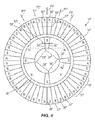
- the encoder could have four index pulses by incorporating four North/South pole pairs on the reference track 30.
- Fig. 4 illustrates such an embodiment, with like parts given like reference numbers plus the double-prime (") symbol.
- each North/South pole pair 34" on the reference track 30" has one pole (e.g., the South pole) with a shorter angular span (i.e., shorter length) than the other pole (e.g., the North pole) of the pole pair 34", and the angular span of that shorter pole encompasses only a single one of the position indicator or detection locations of the high resolution track 14".
- Fig. 5 illustrates a linear-track encoder embodiment 10"' corresponding to the encoder 10" of Fig. 4 .
- Like parts are given like reference numbers plus the triple-prime ("') symbol.
- any reference to a North/South pole pair does not require any specific orientation (i.e., which pole is first/second or left/right in the pair).
- any reference to both a North/South pole junction and a South/North pole junction of a given North/South pole pair simply refers to two adjacent pole junctions defined by the pole pair, without requiring any specific orientation of the pole pair (i.e., which pole is first/second or left/right in the pair).
Landscapes
- Physics & Mathematics (AREA)
- General Physics & Mathematics (AREA)
- Engineering & Computer Science (AREA)
- Theoretical Computer Science (AREA)
- Transmission And Conversion Of Sensor Element Output (AREA)
Claims (7)
- Magnetischer Kodierer (10; 10'; 10"; 10"'), umfassend:eine hochauflösende Spur (14; 14'; 14"; 14"'), die eine Mehrzahl von Nord-/Südpol-Paaren (18; 18'; 18"; 18"') umfasst, die eine Mehrzahl von Pol-Übergängen (22; 22'; 22"; 22"'/26; 26', 26"; 26"') definieren; undeine Referenzspur (30; 30'; 30"; 30"'), die mindestens ein Nord-/Südpol-Paar (34; 34'; 34"; 34"') umfasst, wobei der Kodierer (10; 10'; 10"; 10"') Signale an einer Anzahl von Positionsanzeigestellen (P1; P1'; P1"; P1"'/P2; P2'; P2"; P2"/P3; P3'; P3"; P3"'/P4; P4'; P4"; P4"'/ P5; P5'; P5"; P5'") erfasst, welche Pol-Übergängen der hochauflösenden Spur (14; 14'; 14"; 14"') entsprechen;dadurch gekennzeichnet, dass einer der Pole des mindestens einen Nord/Südpol-Paars (34; 34'; 34"; 34"') der Referenzspur (30; 30'; 30"; 30"') eine kürzere Länge als der andere aufweist; undwobei die Länge des kürzeren Pols des mindestens einen Nord-/Südpol-Paars (34; 34'; 34"; 34"') der Referenzspur (30; 30'; 30"; 30"') so bemessen ist, dass sie nur eine einzige der Positionsanzeigestellen (P3; P3'; P3"; P3"') umfasst, um dadurch einen Index-Impuls zu definieren.
- Magnetischer Kodierer (10; 10'; 10"; 10") nach Anspruch 1,
wobei die Mehrzahl von Pol-Übergängen (22; 22'; 22"; 22"'/26; 26'; 26"; 26"') der hochauflösenden Spur (14; 14'; 14"; 14"') aufeinanderfolgende erste, zweite und dritte Pol-Übergänge (82, 84, 86; 82', 84', 86'; 82", 84", 86"; 82'", 84'", 86"') umfasst;
wobei das mindestens eine Nord-/Südpol-Paar (34; 34'; 34"; 34"') der Referenzspur (30; 30'; 30"; 30"') einen Nord-/Südpol-Übergang (38; 38'; 38"; 38"') und einen Süd-/Nordpol-Übergang (42; 42'; 42"; 42'") definiert; und
wobei der erste Pol-Übergang (82; 82'; 82"; 82"') mit dem Nord-/Südpol-Übergang (38; 38'; 38"; 38"') der Referenzspur (30; 30'; 30"; 30"') ausgerichtet ist, der dritte Pol-Übergang (86; 86'; 86"; 86"') mit dem Süd-/Nordpol-Übergang (42; 42'; 42"; 42"') der Referenzspur (30; 30'; 30"; 30"') ausgerichtet ist, und der zweite Pol-Übergang (84; 84'; 84"; 84"') zwischen den ersten und dritten Pol-Übergängen (82, 86; 82', 86'; 82", 86"; 82"', 86"') ist und mit der Positionsanzeigestelle (P3; P3'; P3"; P3"') übereinstimmt, die den Index-Impuls definiert. - Magnetischer Kodierer (10; 10') nach Anspruch 2, wobei die Referenzspur (30; 30') nur ein Nord-/Südpol-Paar umfasst, wobei der Nord-/Südpol-Übergang (38; 38'), der mit dem ersten Pol-Übergang (82; 82') der hochauflösenden Spur (14; 14') ausgerichtet ist, der einzige Nord-/Südpol-Übergang auf der Referenzspur (30; 30') ist, und wobei der Süd-/Nordpol-Übergang (42; 42'), der mit dem dritten Pol-Übergang (86; 86') der hochauflösenden Spur (14; 14') ausgerichtet ist, der einzige Süd-/Nordpol-Übergang auf der Referenzspur (30; 30') ist.
- Magnetischer Kodierer (10"; 10"') nach Anspruch 1 oder 2, wobei die Referenzspur (30"; 30"') zwei oder mehr Nord-/Südpol-Paare (34"; 34'") umfasst, wobei jedes Paar einen kürzeren Pol umfasst, der so bemessen ist, dass er nur eine einzige der Positionsanzeigestellen (P1"; P1"'/ P2"; P2"'/P3"/P3"'/P4"; P4"'/P5"; P5'") umfasst, um dadurch einen Index-Impuls zu definieren.
- Magnetischer Kodierer (10"; 10"') nach Anspruch 1 oder 2, wobei die Referenzspur (30"; 30"') vier Nord-/Südpol-Paare (34"; 34"') umfasst, wobei jedes Paar einen kürzeren Pol umfasst, der so bemessen ist, dass er nur eine einzige der Positionsanzeigestellen (P1"; P1"'; P2"; P2"'/P3"; P3"'/P4"; P4"'/P5"; P5'") umfasst, um dadurch einen Index-Impuls zu definieren.
- Magnetischer Kodierer (10; 10") nach einem der vorhergehenden Ansprüche, wobei die Referenzspur (30; 30") kreisförmig ist, und wobei die Länge jedes Pols auf der Referenzspur (30; 30") eine Winkelspanne definiert.
- Magnetischer Kodierer (10'; 10") nach einem der vorhergehenden Ansprüche, wobei die Referenzspur (30'; 30"') linear ist, und wobei die Länge jedes Pols auf der Referenzspur (30'; 30"') eine lineare Länge definiert.
Applications Claiming Priority (2)
| Application Number | Priority Date | Filing Date | Title |
|---|---|---|---|
| US201261636335P | 2012-04-20 | 2012-04-20 | |
| PCT/US2013/030731 WO2013158257A2 (en) | 2012-04-20 | 2013-03-13 | Magnetic encoder for producing an index signal |
Publications (2)
| Publication Number | Publication Date |
|---|---|
| EP2839247A2 EP2839247A2 (de) | 2015-02-25 |
| EP2839247B1 true EP2839247B1 (de) | 2016-11-09 |
Family
ID=47989397
Family Applications (1)
| Application Number | Title | Priority Date | Filing Date |
|---|---|---|---|
| EP13711809.7A Active EP2839247B1 (de) | 2012-04-20 | 2013-03-13 | Magnetischer kodierer zur produktion eines indexsignals |
Country Status (6)
| Country | Link |
|---|---|
| US (1) | US9316508B2 (de) |
| EP (1) | EP2839247B1 (de) |
| JP (1) | JP6104364B2 (de) |
| KR (1) | KR101705957B1 (de) |
| CN (1) | CN104246446B (de) |
| WO (1) | WO2013158257A2 (de) |
Cited By (1)
| Publication number | Priority date | Publication date | Assignee | Title |
|---|---|---|---|---|
| WO2023227486A1 (de) | 2022-05-21 | 2023-11-30 | Flux Gmbh | Mehrspuranordnung für linear- und winkelmesssysteme |
Families Citing this family (9)
| Publication number | Priority date | Publication date | Assignee | Title |
|---|---|---|---|---|
| US10024690B2 (en) * | 2015-04-14 | 2018-07-17 | Texas Instruments Incorporated | Incremental rotary encoder using hall effect sensors and magnetic detents |
| DE102015226666A1 (de) * | 2015-12-23 | 2017-06-29 | Frankl & Kirchner GmbH & Co KG Fabrik für Elektromotoren u. elektrische Apparate | Magnetisches Encodersystem für einen Servomotor einer Nähmaschine |
| TWI601939B (zh) * | 2016-03-04 | 2017-10-11 | 國立清華大學 | 絕對位置偵測裝置及方法 |
| DE102017222676A1 (de) * | 2016-12-29 | 2018-07-05 | Robert Bosch Gmbh | Wegsensor |
| HUE061421T2 (hu) | 2017-10-13 | 2023-07-28 | Frankl & Kirchner Gmbh & Co Kg Fabrik Fuer Elektromotoren U Elektrische Apparate | Varrógép meghajtás |
| JP7064966B2 (ja) * | 2018-06-05 | 2022-05-11 | 日本電産サンキョー株式会社 | 磁気式エンコーダ |
| JP2020100214A (ja) * | 2018-12-20 | 2020-07-02 | 日立オートモティブシステムズ株式会社 | ステアリング装置 |
| US20220290965A1 (en) * | 2019-08-27 | 2022-09-15 | Panasonic Intellectual Property Management Co., Ltd. | Position-sensing circuit, position-sensing system, magnet member, position-sensing method, and program |
| CN113028961B (zh) * | 2021-02-26 | 2023-06-06 | 浙江禾川科技股份有限公司 | 一种线性编码器 |
Citations (1)
| Publication number | Priority date | Publication date | Assignee | Title |
|---|---|---|---|---|
| US20090091316A1 (en) * | 2006-04-10 | 2009-04-09 | Timken Us Corporation | Turning device position sensing system and method |
Family Cites Families (31)
| Publication number | Priority date | Publication date | Assignee | Title |
|---|---|---|---|---|
| JPS602602B2 (ja) * | 1977-09-03 | 1985-01-23 | 株式会社ニコン | 原点信号検出用ゼロ信号の発生状態識別装置 |
| JPS57154014A (en) * | 1981-03-20 | 1982-09-22 | Hitachi Ltd | Magnetic rotary encoder |
| JPS6038615A (ja) * | 1983-08-12 | 1985-02-28 | Hitachi Ltd | 磁気式ロ−タリ−エンコ−ダ |
| JPS6086412A (ja) * | 1983-10-19 | 1985-05-16 | Hitachi Ltd | 磁気検出装置 |
| JPH0820271B2 (ja) | 1984-10-03 | 1996-03-04 | 株式会社日立製作所 | 位置や速度を検出する装置 |
| JPS61161417A (ja) * | 1985-01-11 | 1986-07-22 | Sankyo Seiki Mfg Co Ltd | インデツクス信号検出装置 |
| JPH0786406B2 (ja) * | 1985-02-08 | 1995-09-20 | 株式会社日立製作所 | クランク角センサ |
| JPS61278713A (ja) * | 1985-06-03 | 1986-12-09 | Dai Ichi Seiko Co Ltd | 磁気式ロ−タリ−エンコ−ダ− |
| US5097209A (en) * | 1990-02-21 | 1992-03-17 | The Torrington Company | Magnetic encoder and sensor system for internal combustion engines |
| EP0555961B1 (de) * | 1992-02-13 | 1997-07-16 | Japan Servo Co. Ltd. | Absolutkodierer |
| JP3347766B2 (ja) * | 1992-06-08 | 2002-11-20 | 日本トムソン株式会社 | リニアエンコーダ及びこれを具備した案内ユニット |
| JPH074986A (ja) * | 1993-01-21 | 1995-01-10 | Nippondenso Co Ltd | 基準位置検出装置 |
| US5545985A (en) * | 1994-03-16 | 1996-08-13 | Campbell; Peter | Magnetoresistive position sensor including an encoder wherein the magnetization extends greater than 0.5 times the pole pitch below the surface |
| FR2736428B1 (fr) * | 1995-07-04 | 1997-08-08 | Schlumberger Ind Sa | Encodeur impulsionnel pour appareil de distribution de liquide |
| JP3550629B2 (ja) * | 1996-01-24 | 2004-08-04 | 株式会社安川電機 | 光学式エンコーダ |
| JPH10170211A (ja) * | 1996-12-13 | 1998-06-26 | Canon Inc | 位置検出装置及びレンズ位置制御装置 |
| US5898301A (en) | 1997-04-10 | 1999-04-27 | The Torrington Company | Magnetic encoder for producing an index signal |
| FR2769088B1 (fr) * | 1997-09-26 | 1999-12-03 | Roulements Soc Nouvelle | Capteur digital de position relative |
| JP4299901B2 (ja) * | 1997-12-04 | 2009-07-22 | ソニーマニュファクチュアリングシステムズ株式会社 | 位置検出装置 |
| JP2001099681A (ja) * | 1999-10-04 | 2001-04-13 | Sankyo Seiki Mfg Co Ltd | 磁気式エンコーダ装置 |
| JP2003270257A (ja) * | 2002-03-13 | 2003-09-25 | Koyo Seiko Co Ltd | パルサーリングおよびセンサー付き軸受ユニット |
| JP2004061149A (ja) * | 2002-07-25 | 2004-02-26 | Hitachi Ltd | トルクセンサ及びこれを用いた電動パワーステアリング装置 |
| JP2004364354A (ja) * | 2003-06-02 | 2004-12-24 | Mitsumi Electric Co Ltd | ディスクのインデックス信号生成方法及びディスクドライブ装置 |
| US7135859B2 (en) * | 2004-04-06 | 2006-11-14 | Murugesan Sethu | Rotary and angular position sensing |
| US7461317B2 (en) * | 2005-12-15 | 2008-12-02 | Avago Technologies Ecbu Ip (Singapore) Pte. Ltd. | System and method for aligning a quadrature encoder and establishing a decoder processing speed |
| US7999537B2 (en) * | 2006-01-12 | 2011-08-16 | Timken Us Corporation | Magnetic sensor with high and low resolution tracks |
| JP2007198847A (ja) * | 2006-01-25 | 2007-08-09 | Ntn Corp | 回転センサ付き転がり軸受 |
| CN101395450B (zh) * | 2006-03-06 | 2012-06-13 | 日本电产三协株式会社 | 磁编码器装置 |
| US7502703B2 (en) * | 2007-07-09 | 2009-03-10 | Xerox Corporation | Calibration of the fundamental and harmonic once-around velocity variations of encoded wheels |
| WO2009116365A1 (ja) * | 2008-03-17 | 2009-09-24 | 三菱電機株式会社 | 原点位置信号検出器 |
| US8803467B2 (en) * | 2011-02-16 | 2014-08-12 | The Keyw Corporation | Partial arc curvilinear direct drive servomotor |
-
2013
- 2013-03-13 KR KR1020147029389A patent/KR101705957B1/ko active IP Right Grant
- 2013-03-13 WO PCT/US2013/030731 patent/WO2013158257A2/en active Application Filing
- 2013-03-13 JP JP2015506994A patent/JP6104364B2/ja active Active
- 2013-03-13 EP EP13711809.7A patent/EP2839247B1/de active Active
- 2013-03-13 US US14/389,855 patent/US9316508B2/en active Active
- 2013-03-13 CN CN201380020835.7A patent/CN104246446B/zh active Active
Patent Citations (1)
| Publication number | Priority date | Publication date | Assignee | Title |
|---|---|---|---|---|
| US20090091316A1 (en) * | 2006-04-10 | 2009-04-09 | Timken Us Corporation | Turning device position sensing system and method |
Cited By (1)
| Publication number | Priority date | Publication date | Assignee | Title |
|---|---|---|---|---|
| WO2023227486A1 (de) | 2022-05-21 | 2023-11-30 | Flux Gmbh | Mehrspuranordnung für linear- und winkelmesssysteme |
Also Published As
| Publication number | Publication date |
|---|---|
| US20150091554A1 (en) | 2015-04-02 |
| WO2013158257A3 (en) | 2014-01-23 |
| US9316508B2 (en) | 2016-04-19 |
| JP6104364B2 (ja) | 2017-03-29 |
| JP2015517108A (ja) | 2015-06-18 |
| EP2839247A2 (de) | 2015-02-25 |
| KR101705957B1 (ko) | 2017-02-10 |
| CN104246446B (zh) | 2017-05-31 |
| CN104246446A (zh) | 2014-12-24 |
| KR20150014911A (ko) | 2015-02-09 |
| WO2013158257A2 (en) | 2013-10-24 |
Similar Documents
| Publication | Publication Date | Title |
|---|---|---|
| EP2839247B1 (de) | Magnetischer kodierer zur produktion eines indexsignals | |
| EP2999943B1 (de) | System und verfahren zur bereitstellung einer für einen signaturbereich in einem ziel und eine drehrichtung repräsentativen signalcodierung | |
| JP6077675B2 (ja) | 回転部材の少なくとも1つの回転特性を決定するためのセンサ装置 | |
| CN103925933B (zh) | 一种多圈绝对磁编码器 | |
| CN103443590B (zh) | 绝对编码装置及电动机 | |
| CN100491922C (zh) | 磁编码器 | |
| CN102686980B (zh) | 用于检测运动元件位移的磁场传感器装置 | |
| US7915886B2 (en) | Magnetic speed, direction, and/or movement extent sensor | |
| US8659289B2 (en) | Rotating field sensor | |
| CN100594383C (zh) | 无接触检测发生器部件转速和/或位置的带编码器的装置 | |
| US20110291646A1 (en) | Origin position signal detector | |
| KR20090005319A (ko) | 선회 장치 위치 감지 시스템 및 방법 | |
| US20120223703A1 (en) | Sensor arrangement | |
| US20170219380A1 (en) | Sensor for determining at least one rotation characteristic of a rotating element | |
| US20170167897A1 (en) | Angle measurement device and electric motor | |
| CN104062609A (zh) | 检测电路、半导体集成电路装置和磁场旋转角检测装置 | |
| US9400166B2 (en) | Sensor arrangement | |
| US20060186879A1 (en) | Position sensor with compensated magnetic poles | |
| CN202421201U (zh) | 单个霍尔元器件测量电机转向和转速的装置 | |
| GB2366871A (en) | A high resolution position sensor utilising a rotary magnetic encoder | |
| GB2495617A (en) | Contactless sensor two wheeled vehicle steering arrangement | |
| JP2004198425A (ja) | 回転可能なエレメントの回転角を検出するための装置 | |
| JP2005062189A (ja) | 磁気多極エンコーダ | |
| WO2016157812A1 (ja) | 磁気リング、および、この磁気リングを有する回転センサ | |
| KR20130016975A (ko) | 차량 조향각 감지 장치 및 이를 이용한 조향각 산출 방법 |
Legal Events
| Date | Code | Title | Description |
|---|---|---|---|
| PUAI | Public reference made under article 153(3) epc to a published international application that has entered the european phase |
Free format text: ORIGINAL CODE: 0009012 |
|
| 17P | Request for examination filed |
Effective date: 20141114 |
|
| AK | Designated contracting states |
Kind code of ref document: A2 Designated state(s): AL AT BE BG CH CY CZ DE DK EE ES FI FR GB GR HR HU IE IS IT LI LT LU LV MC MK MT NL NO PL PT RO RS SE SI SK SM TR |
|
| AX | Request for extension of the european patent |
Extension state: BA ME |
|
| DAX | Request for extension of the european patent (deleted) | ||
| 17Q | First examination report despatched |
Effective date: 20160311 |
|
| REG | Reference to a national code |
Ref country code: DE Ref legal event code: R079 Ref document number: 602013013777 Country of ref document: DE Free format text: PREVIOUS MAIN CLASS: G01D0005245000 Ipc: G01D0005244000 |
|
| GRAP | Despatch of communication of intention to grant a patent |
Free format text: ORIGINAL CODE: EPIDOSNIGR1 |
|
| RIC1 | Information provided on ipc code assigned before grant |
Ipc: H03M 1/30 20060101ALI20160624BHEP Ipc: G01D 5/244 20060101AFI20160624BHEP Ipc: G01D 5/245 20060101ALI20160624BHEP |
|
| INTG | Intention to grant announced |
Effective date: 20160721 |
|
| GRAS | Grant fee paid |
Free format text: ORIGINAL CODE: EPIDOSNIGR3 |
|
| GRAA | (expected) grant |
Free format text: ORIGINAL CODE: 0009210 |
|
| AK | Designated contracting states |
Kind code of ref document: B1 Designated state(s): AL AT BE BG CH CY CZ DE DK EE ES FI FR GB GR HR HU IE IS IT LI LT LU LV MC MK MT NL NO PL PT RO RS SE SI SK SM TR |
|
| REG | Reference to a national code |
Ref country code: GB Ref legal event code: FG4D |
|
| REG | Reference to a national code |
Ref country code: AT Ref legal event code: REF Ref document number: 844361 Country of ref document: AT Kind code of ref document: T Effective date: 20161115 Ref country code: CH Ref legal event code: EP |
|
| REG | Reference to a national code |
Ref country code: IE Ref legal event code: FG4D |
|
| REG | Reference to a national code |
Ref country code: DE Ref legal event code: R096 Ref document number: 602013013777 Country of ref document: DE |
|
| PG25 | Lapsed in a contracting state [announced via postgrant information from national office to epo] |
Ref country code: LV Free format text: LAPSE BECAUSE OF FAILURE TO SUBMIT A TRANSLATION OF THE DESCRIPTION OR TO PAY THE FEE WITHIN THE PRESCRIBED TIME-LIMIT Effective date: 20161109 |
|
| REG | Reference to a national code |
Ref country code: LT Ref legal event code: MG4D |
|
| REG | Reference to a national code |
Ref country code: NL Ref legal event code: MP Effective date: 20161109 |
|
| REG | Reference to a national code |
Ref country code: FR Ref legal event code: PLFP Year of fee payment: 5 |
|
| REG | Reference to a national code |
Ref country code: AT Ref legal event code: MK05 Ref document number: 844361 Country of ref document: AT Kind code of ref document: T Effective date: 20161109 |
|
| PG25 | Lapsed in a contracting state [announced via postgrant information from national office to epo] |
Ref country code: GR Free format text: LAPSE BECAUSE OF FAILURE TO SUBMIT A TRANSLATION OF THE DESCRIPTION OR TO PAY THE FEE WITHIN THE PRESCRIBED TIME-LIMIT Effective date: 20170210 Ref country code: NL Free format text: LAPSE BECAUSE OF FAILURE TO SUBMIT A TRANSLATION OF THE DESCRIPTION OR TO PAY THE FEE WITHIN THE PRESCRIBED TIME-LIMIT Effective date: 20161109 Ref country code: NO Free format text: LAPSE BECAUSE OF FAILURE TO SUBMIT A TRANSLATION OF THE DESCRIPTION OR TO PAY THE FEE WITHIN THE PRESCRIBED TIME-LIMIT Effective date: 20170209 Ref country code: SE Free format text: LAPSE BECAUSE OF FAILURE TO SUBMIT A TRANSLATION OF THE DESCRIPTION OR TO PAY THE FEE WITHIN THE PRESCRIBED TIME-LIMIT Effective date: 20161109 Ref country code: LT Free format text: LAPSE BECAUSE OF FAILURE TO SUBMIT A TRANSLATION OF THE DESCRIPTION OR TO PAY THE FEE WITHIN THE PRESCRIBED TIME-LIMIT Effective date: 20161109 |
|
| PG25 | Lapsed in a contracting state [announced via postgrant information from national office to epo] |
Ref country code: ES Free format text: LAPSE BECAUSE OF FAILURE TO SUBMIT A TRANSLATION OF THE DESCRIPTION OR TO PAY THE FEE WITHIN THE PRESCRIBED TIME-LIMIT Effective date: 20161109 Ref country code: RS Free format text: LAPSE BECAUSE OF FAILURE TO SUBMIT A TRANSLATION OF THE DESCRIPTION OR TO PAY THE FEE WITHIN THE PRESCRIBED TIME-LIMIT Effective date: 20161109 Ref country code: IS Free format text: LAPSE BECAUSE OF FAILURE TO SUBMIT A TRANSLATION OF THE DESCRIPTION OR TO PAY THE FEE WITHIN THE PRESCRIBED TIME-LIMIT Effective date: 20170309 Ref country code: AT Free format text: LAPSE BECAUSE OF FAILURE TO SUBMIT A TRANSLATION OF THE DESCRIPTION OR TO PAY THE FEE WITHIN THE PRESCRIBED TIME-LIMIT Effective date: 20161109 Ref country code: PT Free format text: LAPSE BECAUSE OF FAILURE TO SUBMIT A TRANSLATION OF THE DESCRIPTION OR TO PAY THE FEE WITHIN THE PRESCRIBED TIME-LIMIT Effective date: 20170309 Ref country code: FI Free format text: LAPSE BECAUSE OF FAILURE TO SUBMIT A TRANSLATION OF THE DESCRIPTION OR TO PAY THE FEE WITHIN THE PRESCRIBED TIME-LIMIT Effective date: 20161109 Ref country code: PL Free format text: LAPSE BECAUSE OF FAILURE TO SUBMIT A TRANSLATION OF THE DESCRIPTION OR TO PAY THE FEE WITHIN THE PRESCRIBED TIME-LIMIT Effective date: 20161109 Ref country code: HR Free format text: LAPSE BECAUSE OF FAILURE TO SUBMIT A TRANSLATION OF THE DESCRIPTION OR TO PAY THE FEE WITHIN THE PRESCRIBED TIME-LIMIT Effective date: 20161109 |
|
| PG25 | Lapsed in a contracting state [announced via postgrant information from national office to epo] |
Ref country code: CZ Free format text: LAPSE BECAUSE OF FAILURE TO SUBMIT A TRANSLATION OF THE DESCRIPTION OR TO PAY THE FEE WITHIN THE PRESCRIBED TIME-LIMIT Effective date: 20161109 Ref country code: SK Free format text: LAPSE BECAUSE OF FAILURE TO SUBMIT A TRANSLATION OF THE DESCRIPTION OR TO PAY THE FEE WITHIN THE PRESCRIBED TIME-LIMIT Effective date: 20161109 Ref country code: RO Free format text: LAPSE BECAUSE OF FAILURE TO SUBMIT A TRANSLATION OF THE DESCRIPTION OR TO PAY THE FEE WITHIN THE PRESCRIBED TIME-LIMIT Effective date: 20161109 Ref country code: DK Free format text: LAPSE BECAUSE OF FAILURE TO SUBMIT A TRANSLATION OF THE DESCRIPTION OR TO PAY THE FEE WITHIN THE PRESCRIBED TIME-LIMIT Effective date: 20161109 Ref country code: EE Free format text: LAPSE BECAUSE OF FAILURE TO SUBMIT A TRANSLATION OF THE DESCRIPTION OR TO PAY THE FEE WITHIN THE PRESCRIBED TIME-LIMIT Effective date: 20161109 |
|
| REG | Reference to a national code |
Ref country code: DE Ref legal event code: R097 Ref document number: 602013013777 Country of ref document: DE |
|
| PG25 | Lapsed in a contracting state [announced via postgrant information from national office to epo] |
Ref country code: IT Free format text: LAPSE BECAUSE OF FAILURE TO SUBMIT A TRANSLATION OF THE DESCRIPTION OR TO PAY THE FEE WITHIN THE PRESCRIBED TIME-LIMIT Effective date: 20161109 Ref country code: SM Free format text: LAPSE BECAUSE OF FAILURE TO SUBMIT A TRANSLATION OF THE DESCRIPTION OR TO PAY THE FEE WITHIN THE PRESCRIBED TIME-LIMIT Effective date: 20161109 Ref country code: BE Free format text: LAPSE BECAUSE OF FAILURE TO SUBMIT A TRANSLATION OF THE DESCRIPTION OR TO PAY THE FEE WITHIN THE PRESCRIBED TIME-LIMIT Effective date: 20161109 Ref country code: BG Free format text: LAPSE BECAUSE OF FAILURE TO SUBMIT A TRANSLATION OF THE DESCRIPTION OR TO PAY THE FEE WITHIN THE PRESCRIBED TIME-LIMIT Effective date: 20170209 |
|
| PLBE | No opposition filed within time limit |
Free format text: ORIGINAL CODE: 0009261 |
|
| STAA | Information on the status of an ep patent application or granted ep patent |
Free format text: STATUS: NO OPPOSITION FILED WITHIN TIME LIMIT |
|
| 26N | No opposition filed |
Effective date: 20170810 |
|
| REG | Reference to a national code |
Ref country code: CH Ref legal event code: PL |
|
| GBPC | Gb: european patent ceased through non-payment of renewal fee |
Effective date: 20170313 |
|
| PG25 | Lapsed in a contracting state [announced via postgrant information from national office to epo] |
Ref country code: MC Free format text: LAPSE BECAUSE OF FAILURE TO SUBMIT A TRANSLATION OF THE DESCRIPTION OR TO PAY THE FEE WITHIN THE PRESCRIBED TIME-LIMIT Effective date: 20161109 Ref country code: SI Free format text: LAPSE BECAUSE OF FAILURE TO SUBMIT A TRANSLATION OF THE DESCRIPTION OR TO PAY THE FEE WITHIN THE PRESCRIBED TIME-LIMIT Effective date: 20161109 |
|
| REG | Reference to a national code |
Ref country code: IE Ref legal event code: MM4A |
|
| PG25 | Lapsed in a contracting state [announced via postgrant information from national office to epo] |
Ref country code: LU Free format text: LAPSE BECAUSE OF NON-PAYMENT OF DUE FEES Effective date: 20170313 |
|
| PG25 | Lapsed in a contracting state [announced via postgrant information from national office to epo] |
Ref country code: LI Free format text: LAPSE BECAUSE OF NON-PAYMENT OF DUE FEES Effective date: 20170331 Ref country code: GB Free format text: LAPSE BECAUSE OF NON-PAYMENT OF DUE FEES Effective date: 20170313 Ref country code: IE Free format text: LAPSE BECAUSE OF NON-PAYMENT OF DUE FEES Effective date: 20170313 Ref country code: CH Free format text: LAPSE BECAUSE OF NON-PAYMENT OF DUE FEES Effective date: 20170331 |
|
| REG | Reference to a national code |
Ref country code: FR Ref legal event code: PLFP Year of fee payment: 6 |
|
| PG25 | Lapsed in a contracting state [announced via postgrant information from national office to epo] |
Ref country code: MT Free format text: LAPSE BECAUSE OF NON-PAYMENT OF DUE FEES Effective date: 20170313 |
|
| PG25 | Lapsed in a contracting state [announced via postgrant information from national office to epo] |
Ref country code: HU Free format text: LAPSE BECAUSE OF FAILURE TO SUBMIT A TRANSLATION OF THE DESCRIPTION OR TO PAY THE FEE WITHIN THE PRESCRIBED TIME-LIMIT; INVALID AB INITIO Effective date: 20130313 |
|
| PG25 | Lapsed in a contracting state [announced via postgrant information from national office to epo] |
Ref country code: CY Free format text: LAPSE BECAUSE OF FAILURE TO SUBMIT A TRANSLATION OF THE DESCRIPTION OR TO PAY THE FEE WITHIN THE PRESCRIBED TIME-LIMIT Effective date: 20161109 |
|
| PG25 | Lapsed in a contracting state [announced via postgrant information from national office to epo] |
Ref country code: MK Free format text: LAPSE BECAUSE OF FAILURE TO SUBMIT A TRANSLATION OF THE DESCRIPTION OR TO PAY THE FEE WITHIN THE PRESCRIBED TIME-LIMIT Effective date: 20161109 |
|
| PG25 | Lapsed in a contracting state [announced via postgrant information from national office to epo] |
Ref country code: TR Free format text: LAPSE BECAUSE OF FAILURE TO SUBMIT A TRANSLATION OF THE DESCRIPTION OR TO PAY THE FEE WITHIN THE PRESCRIBED TIME-LIMIT Effective date: 20161109 |
|
| PG25 | Lapsed in a contracting state [announced via postgrant information from national office to epo] |
Ref country code: AL Free format text: LAPSE BECAUSE OF FAILURE TO SUBMIT A TRANSLATION OF THE DESCRIPTION OR TO PAY THE FEE WITHIN THE PRESCRIBED TIME-LIMIT Effective date: 20161109 |
|
| PGFP | Annual fee paid to national office [announced via postgrant information from national office to epo] |
Ref country code: FR Payment date: 20230324 Year of fee payment: 11 |
|
| P01 | Opt-out of the competence of the unified patent court (upc) registered |
Effective date: 20230613 |
|
| REG | Reference to a national code |
Ref country code: DE Ref legal event code: R082 Ref document number: 602013013777 Country of ref document: DE Representative=s name: KRAUS & LEDERER PARTGMBB, DE |
|
| PGFP | Annual fee paid to national office [announced via postgrant information from national office to epo] |
Ref country code: DE Payment date: 20240320 Year of fee payment: 12 |