EP2836751B1 - Verfahren zum entfernen eines eingegrabenen rohres von einem gelände und schneidmaschine zur durchführung des verfahrens - Google Patents
Verfahren zum entfernen eines eingegrabenen rohres von einem gelände und schneidmaschine zur durchführung des verfahrens Download PDFInfo
- Publication number
- EP2836751B1 EP2836751B1 EP13723249.2A EP13723249A EP2836751B1 EP 2836751 B1 EP2836751 B1 EP 2836751B1 EP 13723249 A EP13723249 A EP 13723249A EP 2836751 B1 EP2836751 B1 EP 2836751B1
- Authority
- EP
- European Patent Office
- Prior art keywords
- pipe
- wall
- cutting
- cut
- section
- Prior art date
- Legal status (The legal status is an assumption and is not a legal conclusion. Google has not performed a legal analysis and makes no representation as to the accuracy of the status listed.)
- Active
Links
Images


Classifications
-
- F—MECHANICAL ENGINEERING; LIGHTING; HEATING; WEAPONS; BLASTING
- F16—ENGINEERING ELEMENTS AND UNITS; GENERAL MEASURES FOR PRODUCING AND MAINTAINING EFFECTIVE FUNCTIONING OF MACHINES OR INSTALLATIONS; THERMAL INSULATION IN GENERAL
- F16L—PIPES; JOINTS OR FITTINGS FOR PIPES; SUPPORTS FOR PIPES, CABLES OR PROTECTIVE TUBING; MEANS FOR THERMAL INSULATION IN GENERAL
- F16L1/00—Laying or reclaiming pipes; Repairing or joining pipes on or under water
- F16L1/024—Laying or reclaiming pipes on land, e.g. above the ground
- F16L1/028—Laying or reclaiming pipes on land, e.g. above the ground in the ground
-
- B—PERFORMING OPERATIONS; TRANSPORTING
- B24—GRINDING; POLISHING
- B24C—ABRASIVE OR RELATED BLASTING WITH PARTICULATE MATERIAL
- B24C3/00—Abrasive blasting machines or devices; Plants
- B24C3/32—Abrasive blasting machines or devices; Plants designed for abrasive blasting of particular work, e.g. the internal surfaces of cylinder blocks
Definitions
- the present invention relates to the technical sector of buried pipes of gas pipelines, oil pipelines and the like.
- pipelines made of steel, polymers or other ductile materials.
- these ductile materials are to be distinguished for example from the cement or stoneware of which drains are made.
- the geological structure of the crossing zone is such that a trenched intervention might provoke landsliding phenomena.
- This method includes digging two ditches at the ends of the portion of pipe which has not been extracted, such as to uncover the ends.
- a splitting element is located in one of the ditches, directly at the end mouth of the residual portion of the pipe, while a drawing device, such as for example a winch, is situated at the other ditch and connected to the splitting element by means of a cable, a chain or other similar transmission means of the motion.
- the splitting element comprises a main variable-section body, for example in the shape of an ogive, tapered in the internal direction of the portion of pipe, but with an increasing section in the opposite direction, up to having a greater size than the aperture of the pipe itself.
- the splitting element comprises a cutting member located above the main body and arranged thereon rather like a dorsal fin or a crest.
- a new section of pipe is fixed to the tail of the splitting element, at the largest section thereof.
- the drawing splitting element When the winch is activated to draw the splitting element, and therefore also the new section of pipe, the drawing splitting element carries out a cutting of the residual portion of the old pipe by means of the cutting member, which enables a splitting thereof following the forcible insertion of the main body, to enable passage of the new section of pipe into the residual portion of the worn conduit.
- the cutting member cuts the residual portion starting from an end edge, the member being located transversal to the wall of the pipe portion, with the edge of the cutting element also cutting the terrain which overlies the portion of pipe itself.
- the aim of the present invention is to obviate the above-explained drawback in the prior art, and others besides, using a process for removing a buried longitudinal portion of pipe from the terrain, which portion is substantially cylindrical and made of a ductile material, according to claim 1, and making available a machine for making cuts in the wall of the buried portion of pipe, according to claim 13.
- the method comprises following fundamental steps, which can either be actuated in succession or in such a way that at least some of them are actuated contemporaneously entirely or in part:
- Step b above is preferably carried out by making on the wall of the portion (P) to be removed at least a through-cut having a helical development with respect to a central longitudinal axis of the portion, such as to obtain a strip having a helically-developing shape.
- the helical shape is such that on one side the strip can function as a bearing structure for the wall of earth surrounding the buried volume receiving the portion of pipe, and can provide a residual structural resistance which prevents the collapsing of the wall of earth.
- the helical spring shape enable the strip to stretch or twist when it is drawn along a curved buried volume, facilitating the passage thereof along the walls of the buried volume and thus enabling an easier extraction.
- the invention constitutes to all effects a trenchless method, i.e. without a ditch opened at a ground level, able to completely remove the portion of buried pipe without leaving residues thereof on site.
- the cutting machine of the invention comprises, in the more general aspects thereof:
- the buried portion of pipe can be cut such as to fashion the strip defined above, thanks to the use of the cutting means.
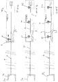
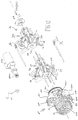
- the method of the invention is disclosed starting from a situation in which the removal of the pipe has been performed, for example by digging a trench, only upstream and downstream of one of the crossing zones in which the prior-art type of removal is not practicable, for example due to the crossing of a banked water course F, schematically denoted in figures from 1 to 10.
- pipes are tubes having a substantially circular section; in practice, for known reasons by the expert in the sector, the section is not exactly constant in shape (i.e. the profile) over the whole length, but which might have oval parts or elliptical parts.
- the method of the invention in its difference embodiments, can comprise a step of making a first and a second cavity S1, S2in the terrain, respectively at a first and a second longitudinal end P1, P2 of the buried portion P to be removed, such as to make the ends accessible.
- Some embodiments might function efficiently by making a single ditch at a single end thereof.
- the digging of the cavities S1, S2 is important because it enables reaching the portion of portion P, and enables having an access for removing from the terrain T the distinct pieces in which the portion P is cut; further, given that the two ends P1, P2 of the portion of pipe define two access mouths to the inside thereof, the two cavities S1, S2 enable inserting the cutting machine 1 of the invention, or other means, in the portion of pipe P, as will be explained at length in the description of the functioning of the machine 1.
- the worksite or worksites are established at the cavities S1, S2 where the pipe-removing personnel is working, and includes containers, generators and tanks, and in general the tools are made ready and the common activities known to experts in the sector of oil-ducts, gas-duct, aqueducts and the like are carried out.
- the first embodiment is particularly suitable for the removal of those portions of pipe P which have a small curvature, for example a substantially circumferential curvature and/or which follows the elastic curvature of the portion P (see figures from 1 to 6).
- This embodiment has among its advantages the relative rapidity and simplicity of actuation.
- step b Before performing step b as indicated above, i.e. in which the portion P is cut, it is first necessary to provide an obturating means O in one of the two cavities S1, S2, which obturating means O can obstruct a section of the portion of pipe P, and having in use a width equal to the size of the section obstructed and a length of its own.
- the obturating means O are of known type, often having a torpedo shape, and substantially comprise a hydraulic element the walls of which, following the activation, are adhered to the internal surface of the walls of the portion of pipe P, such as to sealingly obstruct a section (and thus function as a cap); they are also provided with a cable or like linear drive transmission means, such as to recall them from the position in which they have been inserted in the portion P.
- the obturating means O are mainly necessary because preferably the filler material used in above-cited step d. is of the initially-fluid type, and is able to solidify in time (even over several days); this type of material is chosen because it facilitates the obstruction operations of the underground volume which has housed the portion of the pipe P, and further facilitates the extraction.
- the fluid material can be for example bentonite mud, or any type of stabilised mud comprising aggregate material such as sand, silt, lime or the like, and a bond such as quicklime or the like.
- the fluid filler material prefferably be eco-compatible.
- obturating means O which functions as a cap enables separating theactuation of the method into two parts, defining two distinct longitudinal sections of the portion of pipe P, to be removed at different times, as will be explained in the following, thus enabling extraction from the terrain of even very long portions of pipe.
- step b The following steps are also carried out before step b:
- a first part of step b is carried out, making a closed through-cut, which is incident and transversal to the preliminary cut performed at the obstructed section, such as to select the portion of pipe P by separating the part which contains the first end from the one that contains the second end and the obstructed section ( figure 2 ), such as to obtain in practice two lengths.
- the closed cut is preferably a circular cut located in a transversal plane to the portion of pipe P.
- step b continues by making at least a through-cut on the wall circumscribing said first isolated volume V1, which through-cut extends said closed cut up to the first longitudinal end P1 (see figure 3 ).
- step c. is carried out, where the strip obtained in the first part of step b. is removed from the terrain ( figure 4 ).
- Figures from 3 to 6 denote a mixer station B, part of the worksite, used for releasing, by force of gravity, the filler fluid through the mouth of the first end P1 of the portion of pipe P.
- the filler fluid prefferably to be inserted together with the extraction operations, as it also serves to give structure to the buried volume, as after the cutting operating the portion of pipe has lesser structural resistance ability, and is therefore less efficiently able to support the weight of the overlying terrain T; this is more especially significant after one or more of the distinct pieces have been removed by sliding them out through the cavity S1.
- figure 4 indicates the moment in which a piece K is being extracted (in this description the piece is also referred-to as a strip) from the pieces obtained in the above-indicated way, passing through the first cavity S1, for example by means of one or more vibrating drawing heads H (or "simple"), possibly borne by self-propelling machines (e.g. tracked), or by other means suitable for drawing the pieces of pipe.
- vibrating drawing heads H or "simple”
- self-propelling machines e.g. tracked
- Figure 5 shows the moment in which the whole piece K is removed from the ground and is in the first cavity S1 and, in figure 6 , it can be seen how the piece K is eased onto special supports L, for example made of wood.
- step b. a second part of step b. is actuated, in which at least a through-cut is made on the wall which surrounds the second isolated volume V2, which cut prolongs the cut (or cuts) made at the obstructed section up to the second longitudinal end P2, thus obtaining at least a strip.
- the preliminary cut is made in the section which has to house the obturating means O, in the end thereof placed at or before the second volume V2, it is preferably prolonged transversally to the central axis of the portion of pipe P (the prolongation being a few degrees or fractions of degrees), such that during the second part of step b, it is easier to carry out the through-cut which continues (i.e. prolongs) the preliminary cut of the obturated section.
- step c the strip (or the separated pieces, in the case of several cuts) obtained at the end of the second part of step b is removed from the terrain and at the same time or after, filler fluid is poured into the underground volume which has house the portion of pipe P removed or which is being removed (the latter actions are not illustrated as they can be understood from the previously-described figures).
- step b of the method There are principally two modes in which the single cut or the through-cuts of step b of the method are preferably carried out (except those carried out in a transversal plane which serve to divide the portions of pipe P to be divided into longitudinal portions.
- a through-cut is made on the wall (or walls, after the separation into two parts of the portion of pipe P), which through-cut has a helical development with respect to the central longitudinal axis of the portion, such as to obtain the strip having a helically-developing shape.
- step b where the first cut is on the wall surrounding the first volume V1, followed by the cut surrounding the second volume V2, four helical cuts can be made (four for each piece), such as to obtain in all eight distinct pieces having a helical shape.
- the through-cuts are substantially parallel to the longitudinal central axis of the portion of pipe P and are angularly distanced with respect to the central axis.
- the through-cuts are carried out from inside towards the outside of the portion of pipe, passing through the wall from side to side (as in the case of the use of the machine 1 of the invention), such that during the cut the terrain T in which the portion of pipe P is included is not involved.
- the second version (not illustrated in the figures) of the first embodiment of the method, specially provided for the shorter pipes, is like the first version except for the fact that the obturating means O is not used and that the portion of pipe P is not separated into two lengths and the inside of which is not divided into two volumes.
- step b is carried out in a single solution by making the through-cut or cuts in the wall starting from the second end P2 up to the first end P1 of the portion P, without any need to displace the worksite from the first cavity S1 to the second cavity S2.
- each through-cut extends over all the length of the portion of pipe P.
- the whole buried portion P can be directly extracted in a single piece with a single removal operation.
- the distinct pieces obtained would be four in number and would be removed for example singly directly by the first cavity S1 with the modes already explained.
- the second version can be used for longer portions of buried pipe P as long as sufficiently powerful extraction means are available for extracting separate long pieces.
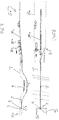
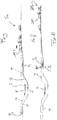
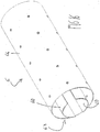
- the second embodiment of the method is particularly provided for removing portions of pipes P which exhibit significant bends so as to assume an upturned trapezoid shape (without the larger side, obviously), as shown in figures 7 , 9 and 10 .
- the shape of the pipe is made necessary, during laying, by the fact that a geographical and/or hydrographical obstacle has to be overcome, of limited width but having a depth (such as the narrow water course F of figures 7, 8 and 10 ).
- the second embodiment is particularly suitable for a case of a portion of pipe with significant bends because it includes the oft-cited cutting step b being actuated to successively separate longitudinal sections of the buried portions of pipe P, making through-cuts in each able to separate the wall of the portion of pipe P which surrounds each sectioninto distinct pieces, and removing the pieces time by time, transporting them away and removing them from the terrain T through one of the above-cited first and second cavity S1, S2 (in the figures, the second cavity S2).
- the separation and removal in succession of the portion of pipe P are carried out in the following ways:
- the distinct pieces obtained are time by time transported away (for example with a carriage 7, represented in figures 7, 8 and 9 , which will be described in the following) and brought out of the terrain T.
- Steps f. and g. are reiterated, applying them to successive sections of the pipe which include the new terminal edge time by time defined, up to cutting and removing a section of the portion of pipe which includes the second end P2 (schematically indicated in figure 10 ).
- the underground volume that is being created is flooded with the filler fluid.
- a seal means is provided (identified by the external container denoted by 5 in the figures, which will be described in the following) for sealingly insulating the part of the portion still to be cut from the empty underground volume under formation and which is filled with filler fluid.
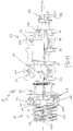
- the cutting machine of the invention includes, in its most general form: a cutting part 11, entirely insertable in said portion of pipe P, comprising cutting means 41 for making at least a through-cut in the wall of the portion of pipe; and a support part 12, for supporting the cutting part 11, also entirely insertable in the portion of pipe P, and comprising abutting means 31, 32, 33 for contemporaneously abutting, at a plurality of points, an internal surface of the portion of pipe so as to engage the machine 1 to the portion of pipe P to be cut.
- part of support 12 is the one which engages to the portion of pipe P and rests there the weight of the machine 1, while the part of cut 11 is supported thereby and can therefore directly make cuts on the wall of the portion P without interference of engaging and support means.
- the machine 1 can be inserted in the portion of pipe P and displaced along it (in the ways described in the following) in order to make the through-cut or cuts to the wall from inside towards the outside.
- the support part 12 can comprise at least a central support frame 30 (for example axialsymmetric as in the figures), connected to the cut part 11, on which central support frame the aforementioned abutting means 31, 32, 33 are mounted.
- a central support frame 30 for example axialsymmetric as in the figures
- the support frame 30 is preferably provided with a central passage 300.
- the abutting means can comprise at least three abutting elements destined to contemporaneously abut the internal surface of the portion of pipe P in three engaging points, and arranged angled with respect to a central axis C1 of the frame (in practice they are arranged radially with respect to the axis C1).
- the angle between the abutting element is selected such that the contemporaneous abutting of the abutting elements 31, 32, 33 and internal surface of the portion P ensured, apart from the support, also an antirotational block of the support part 12 with respect to the portion of pipe P.
- the machine 1 can be made to slide along the longitudinal development of the buried portion P, in order to make the cuts, and at the same time the antirotational block enables reliability in the carrying-out of the cuts and because there is a fixed reference and also because there are no random rotation movements which prejudice the carrying-out of the cuts.
- the abutting elements 31, 32, 33 are preferably angled such as to be equidistant, i.e. crossed by relative planes located at 120° from one another.
- each abutting element comprises at least a pair of arms 31, 32 (but preferably two pairs, parallel as illustrated in the figures) each having a respective end connected to the central frame 30 by means of an internal rotational coupling 310, 320 and the other two respective ends connected to one another and to a wheel 33 by means of at least an external rotational coupling 330.
- each connecting element being mutually movable along an axis that is parallel to the central frame axis C1 and being connected to one another by means of elastic biasing means for urging them together, with the rotation axes of the rotational couplings 310, 320, 330 and the wheels 33 being perpendicular to the axis of the frame C1.
- the wheels 33 enable the machine 1 to slide along the internal surface of the buried portion P and can be made of steel or nylon or any other suitable material.
- the configuration is provided to enable an adapting of the machine 1 to the dimensions of the transversal section of the portion of pipe P, varying continuously the distance between wheels 3 and frame 30.
- regulating means 34 (schematised by the knobs indicated in the figures) can be connected to each pair of internal rotation pairs 310, 320 such as to predetermine (by command of the operator) a distance between the internal rotational couplings, which is a function of the diameter of the portion P to be cut, with the internal couplings subjected at all times to the elastic recall means.
- the adjusting means 34 can be of a type which predetermines a minimum distance between the internal couplings 310, 320 (which corresponds to a maximum distance of the wheel 33 from the frame 30).
- the abutting elements 31, 32, 33 self-adapt so that the support part 12 (and therefore the machine 1) does not lose perfect engagement with the internal surface of the walls of the buried portion P.
- the internal couplings 310, 320 of one of more abutting elements can split apart (with the wheel or wheels 33 nearing the frame),enabling the machine 1 to pass beyond the section, then to return to the predetermined distance on action of the elastic recall means once the aperture of the portion P has returned to the normal dimensions.
- the support part 12 is in practice formed by two components arranged in series and fixed to one another, the structure of which is the one described up to now for the support part in the generalities thereof, i.e. each components comprises a central frame 30 and a plurality of abutting elements 31, 32, 33 arranged in spoke-fashion with respect thereto, comprising the arms, the wheels, the elastic recall means and the adjusting means configured as explained herein above.
- the cutting part 11 of the machine 1 is connected to the support part 12, preferably frontally and rotatably.
- the cutting part 11 can comprise a connecting and support structure 40, connected to the support part 12, and wherein the cutting means comprise at least a cutting device 41 mounted on the connecting structure 40 and able to make at least a cut in the wall of the portion of pipe P, from inside towards outside, passing through the wall from side to side.
- the cutting devices are a plurality (for example four as in the accompanying figures), they are preferably), mounted on the connecting structure 40 in such a way as to be angularly distanced with respect to a central structure axis C2 which passes through the connecting structure 40.
- the cutting devices 41 have a radial arrangement with respect to the axis of the structure C2.
- the axis of structure C2 is preferably coincident with the axis of the frame C1 to define a central machine C axis, with the connecting structure 40 of the cutting part 11 which is connected rotatably to the frame 30 of the part of support 12 with respect to the central axis of the machine C.
- the support part 12 engages antirotationally with the walls of the portion P, with sliding possibility in the direction of the length thereto, and the cutting part can perform both straight cuts, keeping the cutting part still with respect to the support part, and curved cuts, rotating the cutting part with respect to the support part.
- the machine 1 can be used both for carrying out the above-mentioned first cutting mode in which the through-cuts are substantially parallel to the central longitudinal axis of the portion of pipe P, and the second mode where the through-cuts have a helical development with respect to the central axis of the portion of pipe.
- the above-cited closed transversal cuts (for example circular) can be made, which serve to cut off the pieces of wall or to divide the portion P into separate lengths (see the description of the method).
- rotation activating means are provided, preferably formed by: a cogged circular crown 401 mounted on the support structure 40, symmetrical with respect to the axis of structure C2, and positioned in front of the frame 30 of the support part; a pinion 402 for rotatingly activating the crown 401; and one or more electric motors 403 (with possible gear reducers and other accessory means as required) connected to the pinion 402 such as to activate it, the motor 403 being mounted on the part of support 12 of the machine 1.
- the cutting devices 41 are preferably of a type able to make cold cuts, in particular of the water-jet type, each comprising a cutting nozzle 410 for dispensing the cutting liquid.
- the water-jet devices are of known type, even though not in combination with other elements of the invention, and will therefore not be further described in detail, as it is sufficient to note that they include the supply of water and supply of an abrasive powder substance which are blended in a mixing chamber (for example the powder substance is drawn by Venturi effect following the inlet of the water) and the cutting liquid dispensed comprises the mixture of the water and substance at a high pressure (such as 6000 bar).
- the central passage 300 of the support frame 30, which crosses all the support part 12 up to the support structure of the cutting part, serves to accommodate a water supply tube (which can be made of a metal material, very resistant and provided with some flexibility), which is coupled rotatably to the cutting part 12 and is connected to the cutting device 11 (with the modes as shown by way of example below).
- a water supply tube which can be made of a metal material, very resistant and provided with some flexibility
- the distance between nozzles 410 (or rather the outlet openings of the jet) and the wall must be comprised within a given range, preferably about 0.5 cm, because the jet of cutting liquid rapidly loses energy.
- each cutting device 41 is slidable in a perpendicular direction to the axis of the structure C2 (i.e. in a radial direction) such as to be able to vary the distance between the cutting nozzle 410 and the structure axis C2, which implies the adjustment of the distance between the nozzle 410 and the wall to be cut.
- At least an abutting member 42 for each cutting device 41 is mounted solidly to the respective cutting device 41, the abutting member 42 being suitable for abutting the internal surface of the wall of the portion of pipe P and being arranged with respect to the cutting device such that as long as the abutting member 42 abuts the internal surfaces, the cutting nozzle 410 is at a constant cutting distance with respect to the internal surface.
- an elastic contrast means is connected to each cutting device 41 such as to force it to slide distancingly from the structure axis C2.
- each abutting member can comprise a bracketing radially slidable to the support structure 40, located substantially about the relative cutting device as it is equipped with a passage for crossing the nozzle 410, and further equipped with one or more abutting elements 420 mounted on the external face, projecting with respect to the nozzle 410, which can comprise a ball confined freely rotatingly in a respective seating, which ball is arranged such that the distance between the contact point with the wall to be cut and the above outlet opening of the cutting liquid is constant and is the optimal distance for the performing of the cut.
- a water delivery tube 43 can be provided, mounted in the cutting part 11 (see in particular figures 11 and 12 ), which tube 43 is flexible and spiral, with a parallel axis to (or coinciding with) the axis of the structure C2, such as alternatingly to be able to stretch out or wind according to whether the respective cutting device 41 is distancing from or nearing the axis C2.
- Each delivery tube 43 is connected to the supply tube via a tubing further comprising, for example, the cross connections indicated by 430 in the figures.
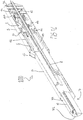
- Figure 2 schematically denotes the machine 1 inserted in the portion of pipe P to be removed from the terrain T, which is connected to the locomotion means thereof located in the first cavity S1, by means of a motion transmission line which is rigid in the length direction, for example a transmission tube formed by a series of metal pigments screwed to one another at the threaded end.
- the locomotion means can comprise a rack located in the first and/or the second cavities S1, S2, on which a pinion enmeshes, activated by a suitable motor, borne by a carriage Z1 which slides above and along the rails Z2 located in the first and/or the second cavity S1, S2, and arranged parallel to the portion of pipe P to be removed (and parallel to the rack, clearly).
- the above-mentioned water supply tube, the pneumatic supply tubes of the abrasive substance, the cavities for the supply of the electrical devices of the machine (such as the machine) and any air breather tubes to allow for the Venturi effect (and if necessary tubes for supply of oil to hydraulic means) can be all arranged parallel and be connected to the above-mentioned transmission tube, and possibly to rest on a series of rollers arranged between the rails Z2.
- the carriage Z1 bears a container which comprises: tanks for the abrasive substance, compressors, pumps for supplying the water at high pressure, etc... while for example the electric generator group Z3 travels laterally to the container.
- the above-mentioned machine 1 can in itself actuate the first embodiment of the method in both the versions (with or without the obturating means O).
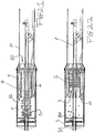
- the removal system 100 which by the way is specially set up for actuating the second embodiment of the method, is illustrated in the main components thereof in figures 13-15 and comprises:
- the system 100 can comprise a transport tube 8 for the filler liquid arranged centrally and axially to the machine 1, the beaker container 5 and the gripping means 5.
- the bottom 51 of the container 5 comprises a single passage for crossing an end portion of the transport tube 8 at which passage the pipe 8 is rotatably fixed to the bottom 51.
- the walls and bottom of the external container 5 sealingly close on the tube 8, such as to fluid-dynamically isolate the inside of the container 5 with respect to the outside except for the passage represented by the tube 8 itself.
- tube 8 described above is destined to be fluid-dynamically connected to the mixer station B and to appropriate pumping means.
- the machine 1 In order to enable crossing of the tube 8 by the filler fluid, the machine 1 will have a central axial passage over the whole length thereof, and the tube for supplying the water will be arranged out-of-axis with respect to the axis C of the machine 1 and fixed to the cutting part 11 with a rotatable coupling, such as to enable rotation of the cutting part 11 with respect to the support part 12,
- the external beaker container 5 can comprise, fixed along the edge of the mouth defined by the access opening 50, a plurality of projecting elements 52 inclined towards the axis of the container, distancingly from the lateral wall, subject to the action of elastic contrast means to splitting, which engage the wall of the portion of pipe P once the section to be cut has been received inside the container 5, with the aim of ensuring a good anchoring to the portion P by the container 5 and the other components of the system 100 contained therein, and as a digging means for softening the terrain T about the portion of pipe.
- the system 100 is arranged at the first end of the portion of pipe P2 to be removed, including or not the shuttle 7 which in the figures is illustrated by way of example separated from the rest of the system 100.
- a section S of the buried portion, the machine 1 and the gripping device 5 are in the external container 5 (it will be explained in the following how they are arranged with respect to one another).
- the machine 1 can be connected to the carriage Z1 and to the container in the way already described, while the external container 5 and the gripping device 6 are movable thanks to winches or similar displacing means to which they are connected by a cable or other linear means for transmission of motion.
- the machine 1 is activated such as to cut the wall of the section S and, in order to do this, the carriage Z1 is pulled, such as to carry out the cuts over all the length of the section S and divide it into distinct pieces (with modes specified in the following), which pieces are initially gripped by the gripping means 5 and then taken in delivery by the shuttle 7 that takes them away towards the second end P2 of portion where they are collected by the personnel working on the second cavity S2.
- a buried empty volume is formed downstream of the system 100, which is then filled under pressure by the filler liquid, via the tube denoted by 8 in the figures.
- the system includes the beaker container 5, the inside thereof (obviously apart from the inside of the tube 8) and all the part of the portion of pipe P downstream of the container 5 are sealed with respect to the filled underground volume.
- the gripping device 6 comprises an external body, in a beaker conformation, completely inserted in the external container 5 and connected rotatably thereto with respect to a common central axis, having a tubular lateral wall 64 parallel to the lateral wall of the external container 5 and having an opening 63 opposite the bottom and facing the opening 63 of the container 50.
- the body has a bottom 62 facing the bottom of the external container 5 which contains it, at which bottom 62 the rotation mechanism of the body of the gripping device is arranged with respect to the external container (for example comprising a motor and a crown mechanism 65 that is internally cogged/pinion).
- the gripping device 6 is preferably mounted in the external container 5 such a to be axially blocked with respect thereto and to be able only to rotate therein.
- a passage is afforded in the bottom 62 for the fluid transport tube 8 at which there is a rotatable connection between the body 64, 62 and the tube 8.
- the gripping device 5 can further comprise a plurality of elongate gripping elements 60, (preferably having a tile shape, or rather a longitudinal sector of a tubular wall), angularly distanced with respect to the common central axis and having a length thereof parallel to the axis, which elongate elements 60 are each connected to the internal surface of the tubular wall 64 by a respective pantograph 61 (for example connected to oil-dynamicactuating means) so as to define said gripping means, in which gripping means elastic retaining means (not illustrated) are further comprised, arranged between each elongate element 60 and the internal surface of the tubular wall 64 and configured such as to engage, by interference fit, the wall of the section S of the portion P of pipe to be cut or said distinct pieces thereof, upon having made the cuts.
- the dimensions of the external container 5 and the gripping device 6 are selected such as when the container 5 engages with the buried portion P the wall of the section S housed therein enters the beaker body of the gripping device, being placed between the tubular wall 64 thereof and the elongate elements 60 (which are preferably four in number and angularly equidistanced), which are parallel to the wall of the section S to be cut.
- the wall of the section S inserted in the gap between the tubular wall 64 of the body and the elongate elements 60 is engaged by the elastic retaining means which can be constituted by a plurality of arched members, made of an elastic material such as for example steel, arranged in series both on the external face of the elongate elements and on the internal face of the tubular wall of the beaker body, and having an end fixed to the respective face on which they are arranged and a free curved end in an opposite direction to the openings 63, 50 of the container 5 and the gripping device 6, such that the terminal edge of the section S which enters the gap presses on the convexity of the arched members such that they give way such as to enable insertion, thus elastically loading and pressing together on both the internal and external surfaces of the wall of the second S, such as to engage it by friction interference.
- the elastic retaining means which can be constituted by a plurality of arched members, made of an elastic material such as for example steel, arranged in series both on the external face of the
- the system 100 is preferably configured such that the external container 5 has an internal volume that is sufficiently long to accommodate in series, starting from the mouth, the gripping device 6, the cutting machine 1 and the means 65 for rotating the gripping device in the container 5.
- the section S still to be cut is housed in the container 5 and engaged to the gripping device 5, in the above-described ways, and, in the internal volume rear of the gripping device, in the following the housing volume A, the cutting machine 1 is completely housed and is thus distanced from the gripping device and the second S; rotating means 65 of the device 5 are located behind the machine 1, for example with the interposing of a separating wall 620 with respect to the housing volume, also clearly provided with a passage for the transport tube 8 of the filler fluid, to which the wall is rotatably coupled.
- the system 100 is preferably arranged and configured in the following way.
- the gripping device has four elongate gripping elements 60 having a same angular distance (not nil) from one another (and each having a circular-progression transversal profile having a shorter length than a right-angle) arranged in such a way that in a front view they are respectively at 12 o'clock, 3 o'clock, 6 o'clock and 9 o'clock of a clock face.
- two superposed elements 60 are ideally separated into two symmetrical halves by a vertical plane passing through the central axis of the external container 5, while the other two elements 60 are flanked and ideally divided into two symmetrical halves by a horizontal plane which also passes through the central axis.
- the cutting machine 1 has four cutting devices 41, also angularly equidistanced to one another and each equidistanced (ideally by 45 degrees) with respect to the two planes of symmetry cited above in the preceding paragraph (and thus located respectively at half-past one, half-past 4, half-past seven and half-past ten).
- the cutting machine 1 is moved axially in the external container 5, bringing it within thesection, such that the cutting devices 41 directly face the wall of the section in the spaces between an elongate element 60 and the other, and can be activated while the machine is drawn towards the mouth 50 of the beaker container 5 (see figure 22 ).
- the lateral wall 64 of the gripping device is preferably made of (or internally clad with) a very hard material (such as Widia), especially in the case of use of water-jet technology so that the jet, after having passed through the wall of the section S, does not damage the gripping device 5 wall.
- a very hard material such as Widia
- Figure 23 represents the moment in which the machine has finished making four through-cuts in section S, and the cutting devices 41 have passed beyond the elongate elements 60.
- the machine 1 is astride the gripping device 5, the external container 6 and the portion of pipe P, with the cutting devices 41 between the front opening 63 of the gripping device and the mouth 51 of the external beaker container 5.
- the cutting part 11 of the machine 1 rotates about the axis C and cuts the cut wall of section S of buried portion P into four distinct parts.
- the pantographs 61 are activated to split the elongate gripping elements 60 (nearing them to the tubular wall 64) such as to separate the distinct pieces 10 retained thereby, annulling the structural resistance they have when contiguous, due to the key-turning principle, and such as to obtain space for the following operations.
- the gripping element 60 located superiorly (at twelve o'clock, to use the terminology specified above) is lowered by the respective pantograph 61, with the relative distinct piece 10, into a delivery position.
- the transport shuttle in known ways explained in the following, takes the piece 10 in, and takes it away from the elongate element 60 which, freed of the piece 10, returns into the original position thereof.
- the rotating means 65 of the gripping device 5 rotate the gripping device 5 by 90°, which can freely occur as the gripping device has rotatable couplings with the beaker container 5 and also with the transport tube 8 of the filler liquid (see figure 25 ).
- a gripping element 60 which was located laterally is brought to 12 o'clock and this can occur without the respective distinct piece 10 falling by virtue of the elastic retaining means and the arrangement thereof in the gripping device 6.
- the transport shuttle 7 comprises a support carriage 71 able to slide in the portion of buried pipe P between the end P2 to which it takes the distinct pieces 10 of wall such as to remove them, and a front position to the elongate elements 60 of the gripping device 6, and further comprises a removing and collecting drawer 72 able to house a plurality of distinct cut pieces 10, arrangeable parallel to the portion of pipe P and the above-cited elongate elements 60.
- the gripping element 60 positioned at 12 o'clock (or it may have lowered) and the shuttle can be activated to receive the piece of wall 10 resting on the element 60 (more precisely on the elastic means).
- the drawer 72 is able to slide with respect to the carriage 71 between an extending collecting position E (see figures 19 and 25 ) in which it is projectingly located with respect to the carriage 71, and a retracted collecting position, and has dimensions such as to be able to surround an elongate element 60 bearing a respective piece 10 of section wall S located above it.
- the shuttle 7 comprises hooking means (not illustrated and described in the following in an embodiment) mounted on the drawer 72 and able to hook the piece of wall 10 following the displacement of the drawer intothe collecting position E,and able to draw the piece 10 while the drawer 71 displaces towards the collecting position up to releasing it restingly into the drawer 72 following arrival thereof in the collecting position.
- the drawer 72 can project beyond the carriage 71 such as to reach the upper elongate element 60 with the load, and surround it (as the drawer preferably is substantially tubular in shape, including a bottom for the support of the pieces), at which the hooking means hood the piece to be collected, which is slid above the elongate element while the drawer retreats towards the collecting position, up to beyond the front edge of the element 60 such that the piece falls onto the bottom of the drawer 72.
- the drawer 72 must be able to contain in stacking fashion all the pieces 10 into which the section S of wall is cut, i.e. four pieces in the above-described example.
- the shuttle 7 As the shuttle 7 has to reach inside the beaker container 6, it has to pass above the tub 8 for the filler liquid, and to do this it can be saddle-shaped, such as the one shown in the figures, having a gully or a lower crook which receives the tube without friction interference and enables the free axial sliding of the carriage 72.
- the carriage has a periphery defined by a deformed tubular wall forming a saddleand exhibits slots to enable wheels located internally to contact the walls of the portion of pipe P so that it can slide.
- the shuttle 7 can be self-propelling, and thus include a motor, or can be moved by actuating means located in the worksite S2 and connected to the carriage 71 by drive transmission means for the purpose (for example comprising jointed rigid rods).
- the hooking means can comprise one or more pendulums, each having an end connected to the upper part of the carriage 71 and having a hook at the other end.
- the pendulums are foldable towards the inside of the drawer 71, following the abutment thereof with the piece 10 to be collected, when the piece 10 is moved towards the extended position E thereof, then to straighten by force of gravity when they have passed beyond the further edge of the piece 10, such as to engage the edge with the hook.
Landscapes
- Engineering & Computer Science (AREA)
- Mechanical Engineering (AREA)
- General Engineering & Computer Science (AREA)
- Excavating Of Shafts Or Tunnels (AREA)
- Electric Cable Installation (AREA)
Claims (19)
- Verfahren zum Entfernen, aus einem Gelände (T), eines eingegrabenen Längsabschnittes (P) eines im wesentlichen zylindrischen Rohres aus einem duktilen Werkstoff und von der Gattung, die für den Einsatz in Erdölpipelines, Wasserrohrleitungen, Gasrohrleitungen oder dergleichen geeignet ist, wobei dieses Verfahren die folgenden Schritte beinhaltet:a. Ausheben zumindest einer Baugrube (S1, S2) in dem Gelände (T), an einem längsseitigen Ende (P1, P2) des zu entfernenden eingegrabenen Abschnittes (P), um dieses Ende zugänglich zu machen;b. Anfertigen von zumindest einem durchgehenden Schnitt in der Wand des zu entfernenden Rohrabschnittes (P), um zumindest einen Streifen zu erhalten, der zwei einander gegenüberliegende Längskanten aufweist, welche eine Breite des Streifens definieren, die kleiner ist als der Umfang der Wand des Rohrabschnittes (P);c. Nehmen des Streifens und Entfernen des Streifens aus dem Gelände durch die Baugrube (S1, S2) hindurch; undd. Verschließen des unterirdischen Volumens, in dem der Rohrabschnitt (P) untergebracht war, und der Baugrube (S1, S2) mit einem zunächst fließfähigen und sich mit der Zeit verfestigenden Verfüllmaterial ("Flüssigboden"),worin während des Schrittes a. eine erste und eine zweite Baugrube (S1, S2) ausgehoben werden, und zwar jeweils an einem ersten und einem zweiten längsseitigen Ende (P1, P2) des zu entfernenden eingegrabenen Abschnittes (P);
worin, vor der Durchführung von Schritt b., die folgenden Schritte ausgeführt werden:- Bereitstellen eines Verschlussmittels (O), geeignet zum Verschließen eines Teilabschnitts des Rohrabschnittes (P), das im Gebrauch eine Weite aufweist, die gleich der Weite des verschlossenen Teilabschnitts ist und eine eigene Länge aufweist;- Anfertigen von zumindest einem durchgehenden Schnitt an einer Wand eines Teilabschnitts des Rohrabschnittes (P), der dafür bestimmt ist, mit dem Verschlussmittel (O) verschlossen zu werden, wobei sich dieser Schnitt über eine Länge des Rohrabschnittes (P) erstreckt, die zumindest gleich der Länge ist, die das Verschlussmittel im Gebrauch aufweist; und- Einsetzen des Verschlussmittels (O) in den Rohrabschnitt (P), so dass es den Teilabschnitt verschließt, an dem der Schnitt ausgeführt wurde, um somit in dem Rohrabschnitt (P) ein erstes und ein zweites Volumen (V1, V2) zu definieren, die fluiddynamisch voneinander isoliert sind;und worin:- ein erster Teil von Schritt b. ausgeführt wird, indem ein geschlossener durchgehender Schnitt ausgeführt wird, der einfallend zu dem am verschlossenen Teilabschnitt hergestellten Schnitt ist, um den Rohrabschnitt (P) aufzuteilen, indem der Teil, der das erste Ende (P1) enthält, von dem Teil abgetrennt wird, der das zweite Ende (P2) und den verschlossenen Teilabschnitt enthält;- danach der erste Teil von Schritt b. fortgesetzt wird, indem zumindest ein durchgehender Schnitt auf der Wand angefertigt wird, die das erste isolierte Volumen (V1) umschreibt, wobei dieser durchgehende Schnitt den geschlossenen Schnitt bis zu dem ersten längsseitigen Ende (P1) hin verlängert, so dass ein Streifen erhalten wird;- danach Flüssigboden in das erste Volumen (V1) eingegossen wird und, gleichzeitig oder daran anschließend, der erste Teil von Schritt c. ausgeführt wird, worin der im ersten Teil von Schritt b. erhaltene Streifen aus dem Gelände entfernt wird;- danach ein zweiter Teil von Schritt b. ausgeführt wird, in dem zumindest ein durchgehender Schnitt auf der Wand angefertigt wird, die das zweite isolierte Volumen (V2) umschreibt, wobei dieser Schnitt den an dem verschlossenen Teilabschnitt angefertigten Schnitt bis zu dem zweiten längsseitigen Ende (P2) hin verlängert, so dass ein weiterer Streifen erhalten wird; und- danach das Verschlussmittel (O) von dem Rohrabschnitt entfernt wird, indem es durch das zweite Ende geführt wird; und dann- ein zweiter Teil von Schritt c. ausgeführt wird, worin der am Ende des zweiten Teils von Schritt b. erhaltene Streifen aus dem Gelände entfernt wird und, gleichzeitig oder daran anschließend, Flüssigboden in das unterirdische Volumen gegossen wird, in dem der Rohrabschnitt (P) untergebracht war, der bereits entfernt wurde oder gerade entfernt wird. - Verfahren nach dem vorhergehenden Anspruch, worin Schritt b. ausgeführt wird, indem auf der Wand des zu entfernenden Abschnitts (P) zumindest ein durchgehender Schnitt mit spiralförmigem Verlauf relativ zu einer mittleren Längsachse des Abschnittes angefertigt wird, um einen Streifen mit spiralförmig verlaufender Form zu erhalten.
- Verfahren nach dem vorhergehenden Anspruch, worin Schritt b. ausgeführt wird, indem eine Vielzahl durchgehender Schnitte auf der Wand des Abschnittes (P) angefertigt werden, um diesen in mehrere einzelne Stücke aufzuteilen.
- Verfahren nach dem vorhergehenden Anspruch, worin Schritt b. ausgeführt wird, indem auf der Wand des zu entfernenden Abschnitts (P) eine Vielzahl durchgehender Schnitte angefertigt werden, die im Wesentlichen parallel zu einer mittleren Längsachse des Abschnittes (P) sind, wobei diese Schnitte relativ zu der mittleren Achse in Winkelabständen angeordnet sind.
- Verfahren nach einem der vorhergehenden Ansprüche, worin der/die durchgehende/n Schnitt/e an dem Rohrabschnitt (P) von innen nach außen, von einer Seite zur anderen Seite durch die Wand gehend, ausgeführt wird/werden.
- Verfahren nach einem der vorhergehenden Ansprüche, worin sich der/die durchgehende/n Schnitt/e über die gesamte Länge des Rohrabschnittes (P) von dessen erstem Ende bis zu dessen zweitem Ende (P1, P2) erstrecken.
- Verfahren nach Anspruch 1, worin Schritt b. ausgeführt wird, indem aufeinanderfolgend längliche Teilabschnitte (S) des eingegrabenen Rohrabschnittes (P) abgetrennt werden, indem in jedem davon durchgehende Schnitte angefertigt werden, die geeignet sind, die Wand des Rohrabschnittes, die den jeweiligen Teilabschnitt (S) umschreibt, in einzelne Stücke aufzuteilen, und nach und nach diese Stücke zu entfernen und die Stücke abzutransportieren, indem sie durch eine der ersten und zweiten Baugruben (S1, S2) aus dem Gelände entfernt werden.
- Verfahren nach dem vorhergehenden Anspruch, worin das aufeinanderfolgende Abtrennen und Entfernen der Teilabschnitte des Rohrabschnittes wie folgt ausgeführt werden:e. der erste Teilabschnitt (S), der geschnitten und entfernt wird, beinhaltet eine Endkante des Rohrabschnittes (P), die in dem ersten Ende (P1) des Rohrabschnittes enthalten ist;f. eine Vielzahl durchgehender Schnitte werden auf der Wand des Rohrabschnittes (P) ausgehend von der Endkante und über eine bestimmte Länge des Abschnittes angefertigt, um mehrere Wandstücke zu definieren, die ein einzelnes freies Ende an der Endkante aufweisen und die eine Länge aufweisen, die eine Länge des ersten Teilabschnittes (S) definiert;g. ein geschlossener durchgehender Schnitt wird ausgeführt, der in einer zu dem Rohrabschnitt (P) quergerichteten Ebene enthalten ist, in einer Entfernung von der Endkante, die im Wesentlichen der Länge des Teilabschnittes (S) entspricht, um die Wand des Rohrabschnittes, die den Teilabschnitt umschrieben hatte, in mehrere einzelne Stücke aufzuteilen und um somit eine neue Endkante zu definieren; unddie Schritte f. und g. werden wiederholt ausgeführt, indem sie auf aufeinanderfolgende Teilabschnitte des Rohrs angewendet werden, die nach und nach jeweils die neue definierte Endkante enthalten, bis schließlich ein Teilabschnitt des Rohrabschnittes geschnitten und entfernt wird, der das zweite Ende (P2) enthält.
- Schneidmaschine zum Anfertigen von Schnitten in einer Wand eines eingegrabenen Längsabschnittes (P) eines Rohres von der Gattung, die für den Einsatz in Erdölpipelines, Wasserrohrleitungen, Gasrohrleitungen oder dergleichen geeignet ist, Folgendes beinhaltend:ein Schneidteil (11), das vollständig in den Rohrabschnitt (P) einführbar ist und Schneidmittel (41) zum Anfertigen von zumindest einem durchgehenden Schnitt in der Wand des Rohrabschnittes beinhaltet; und ein Trägerteil (12), zum Tragen des Schneidteils (11), das ebenfalls vollständig in den Rohrabschnitt (P) einführbar ist und Anschlagmittel (31, 32, 33) für das gleichzeitige Anschlagen, an mehreren Punkten, gegen eine innere Oberfläche des Rohrabschnittes beinhaltet, um die Maschine (1) in Eingriff mit dem zu schneidenden Rohrabschnitt (P) zu bringen, und dadurch gekennzeichnet, dass:das Schneidteil (11) drehbar mit dem Trägerteil (12) verbunden ist, wobei die Maschine (1) kurvige Schnitte in der Wand des Rohrabschnittes (P) ausführen kann, und dadurch, dass das Schneidteil (11) eine Verbindungs- und Trägerstruktur (40) beinhaltet, die mit dem Trägerteil (12) verbunden ist, und worin die Schneidmittel zumindest eine Schneidvorrichtung (41) beinhalten, die auf der Verbindungsstruktur (40) montiert und in der Lage ist, zumindest einen Schnitt in der Wand des Rohrabschnittes (P), von innen nach außen, von einer Seite zur anderen Seite durch die Wand gehend, auszuführen, worin jede Schneidvorrichtung (41) eine Wasserstrahl-Schneidvorrichtung ist und eine Schneiddüse (410) zur Ausgabe der Schneidflüssigkeit beinhaltet, und worin jede Schneidvorrichtung (41) in einer orthogonalen Richtung zu der Strukturachse (C2) derart gleitend verschiebbar ist, so dass der Abstand zwischen der Schneiddüse (410) und der Strukturachse verändert werden kann.
- Maschine nach dem vorhergehenden Anspruch, worin das Trägerteil (12) zumindest einen mittleren Trägerrahmen (30) beinhaltet, der mit dem Schneidteil (11) verbunden ist, wobei auf diesem mittleren Trägerrahmen (30) die Anschlagmittel (31, 32, 33) montiert sind, und diese Anschlagmittel zumindest drei Anschlagelemente beinhalten, die dafür bestimmt sind, gleichzeitig an drei Eingriffspunkten gegen die innere Oberfläche des Rohrabschnittes anzuschlagen, und die relativ zu einer mittleren Achse (C1) des Rahmens, die durch den Trägerrahmen führt, winklig angeordnet sind, wobei die Winkelstellung zwischen den Anschlagelementen derart gewählt ist, dass das gleichzeitige Anschlagen zwischen Anschlagelementen und innerer Oberfläche des Abschnittes (P) neben der tragenden Wirkung auch eine Rotationssicherung gegen das Verdrehen des Trägerteils (12) relativ zu dem Rohrabschnitt sicherstellt.
- Maschine nach dem vorhergehenden Anspruch, worin jedes Anschlagelement zumindest ein Paar Arme (31, 32) beinhaltet, von denen die jeweils einen entsprechenden Enden über eine interne Drehkupplung (310) mit dem mittleren Rahmen (30) verbunden sind und die anderen beiden entsprechenden Enden über zumindest eine externe Drehkupplung (330) miteinander und mit einem Rad (33) verbunden sind, wobei die inneren Drehkupplungen (310) jedes Verbindungselements entlang einer Achse gegeneinander beweglich sind, die parallel zu der mittleren Rahmenachse (C1) ist, und durch federelastische Vorspannmittel zusammengehalten werden, wobei die Drehachsen der Drehkupplungen (310, 330) und der Räder (33) orthogonal zu der Achse (C1) des Rahmens sind.
- Maschine nach Anspruch 9, worin das Schneidteil (11) eine Vielzahl von Schneidvorrichtungen (41) beinhaltet, die derart auf der Verbindungsstruktur (40) montiert sind, dass sie relativ zu einer durch die Verbindungsstruktur führenden mittleren Strukturachse (C2) in Winkelabständen angeordnet sind.
- Maschine nach Anspruch 9, worin zumindest ein Anschlagorgan (42) für jede Schneidvorrichtung (41) fest auf der entsprechenden Schneidvorrichtung montiert ist, wobei das Anschlagorgan dafür vorgesehen ist, gegen die innere Oberfläche des Rohrabschnittes (P) anzuschlagen und relativ zu der Schneidvorrichtung derart angeordnet ist, dass sich, so lange das Anschlagorgan (42) gegen die innere Oberfläche der Wand des Rohrabschnittes anschlägt, die Schneiddüse (410) in einem konstanten Schneidabstand von der genannten inneren Oberfläche befindet, und worin ein federelastisches Vorspannmittel derart mit jeder Schneidvorrichtung verbunden ist, dass es deren Gleitbewegung weg von der Strukturachse (C2) bewirkt.
- Maschine nach Anspruch 9, worin zumindest eine Wasserzuleitung (43) für jede Schneidvorrichtung (41) in dem Schneidteil (11) montiert ist, wobei diese Zuleitung (43) flexibel und spiralförmig ist, mit einer zur Strukturachse (C2) parallelen Achse, so dass sie wechselweise abgerollt oder aufgerollt werden kann, je nachdem, ob sich die entsprechende Schneidvorrichtung von der Achse weg oder auf diese zu bewegt.
- Maschine nach den Ansprüchen 10, 12 und 14, worin die Strukturachse (C2) mit der Rahmenachse (C1) übereinstimmt, um eine mittlere Maschinenachse (C) zu definieren, und worin die Verbindungsstruktur (40) des Schneidteils um diese mittlere Maschinenachse (C) drehbar mit dem Rahmen (30) des Trägerteils verbunden ist.
- Ein Ausbausystem zum Entfernen, aus dem Gelände (T), eines eingegrabenen Längsabschnittes (P) eines Rohres, das zur Anwendung in Ölpipelines, Wasserrohrleitungen, Gasrohrleitungen oder dergleichen geeignet ist, Folgendes beinhaltend:zumindest eine Schneidmaschine (1) nach einem der Ansprüche von 9 bis 15;einen externen Behälter (5), der becherartig geformt und geeignet ist, die Schneidmaschine (1) zu enthalten, welcher Querabmessungen aufweist, die größer sind als die des Rohrabschnittes (P), und der eine Seitenwand beinhaltet, die an einem Ende durch eine Bodenwand (51) geschlossen ist, und an einem gegenüberliegenden Ende eine Öffnung (50) aufweist, die geeignet ist, mit der Wand des Rohrabschnittes (P) in Eingriff zu treten, so dass die Seitenwand des Behälters (5) einen Teilabschnitt (S) des Rohrabschnittes (P) umschreiben kann, der ein Ende (P1, P2) davon beinhaltet, und so dass die Innenseite des Behälters (5) mit der Innenseite des Rohrabschnittes in Verbindung steht;zumindest eine Greifvorrichtung (6), die geeignet ist, in das Innere des Behälters (5) eingeführt zu werden und die Greifmittel (60, 61) beinhaltet, um die einzelnen Stücke festzuhalten, die durch das Anfertigen der Schnitte in der Wand des Teilabschnittes (S) des Rohrabschnittes durch die Schneidmaschine (1) erhalten wurden;zumindest ein Transport-Pendelfahrzeug (7), das innerhalb des eingegrabenen Rohres beweglich ist und geeignet ist, von der Greifvorrichtung (6) die einzelnen Stücke zu übernehmen und diese über das Ende, das dem Ende gegenüberliegt, an dem der becherförmige Behälter (5) angebracht ist, aus dem Rohrabschnitt (P) heraus zu befördern;Mittel zum Verschieben des becherartigen Behälters (5) und der darin enthaltenen Greifvorrichtung (6);Mittel (Z1, Z2) zum Bewegen der Schneidmaschine (1) in dem Behälter und in dem Rohrabschnitt;Mittel (8, B) zur Ausgabe von Verfüllmaterial in das unterirdische Volumen, das von dem Rohrabschnitt (P) zurückgelassen wurde, der in die einzelnen Stücke aufgeteilt und von dem Pendelfahrzeug nach außen transportiert wurde.
- System nach dem vorhergehenden Anspruch, worin die Greifvorrichtung einen becherförmigen externen Körper beinhaltet, der vollständig in den externen Behälter (5) eingeführt ist, beinhaltend eine rohrförmige Seitenwand (64) und um eine gemeinsame mittlere Achse drehbar mit dem externen Behälter verbunden, eine der Öffnung des Behälters zugewandte Öffnung (63), und eine Vielzahl länglicher Greifelemente (60) beinhaltend, die relativ zu der gemeinsamen mittleren Achse in Winkelabständen angeordnet sind und eine Länge parallel zu dieser Achse aufweisen, wobei diese länglichen Elemente (60) jeweils mit der inneren Oberfläche der rohrförmigen Wand (64) über einen entsprechenden Pantographen (61) verbunden sind, um die genannten Greifmittel zu definieren, worin diese Greifmittel ferner elastische Haltemittel beinhalten, die zwischen jedem länglichen Element (60) und der inneren Oberfläche der rohrförmigen Wand (64) angeordnet und derart konfiguriert sind, dass sie mittels Presspassung in Eingriff mit der Wand des Teilabschnittes (S) des zu schneidenden Rohrabschnittes (P) oder den einzelnen Stücken davon treten, nachdem die Schnitte ausgeführt wurden.
- System nach dem vorhergehenden Anspruch, worin das Transport-Pendelfahrzeug (7) einen Trägerwagen (71) beinhaltet, der geeignet ist, innerhalb des eingegrabenen Rohres (P) hin und her zu laufen zwischen dem Ende (P2), an das er die einzelnen Wandstücke befördert, um sie zu entfernen, und einer Position frontal gegenüber den länglichen Elementen (60) der Greifvorrichtung (6), und ferner einen Sammeleinschub (72) zur Aufnahme einer Vielzahl von einzelnen geschnittenen Stücken (10), der parallel zu dem Rohrabschnitt (P) und den länglichen Elementen angeordnet werden kann, wobei dieser Einschub (72) dafür bestimmt ist, relativ zu dem Wagen gleitend bewegt zu werden zwischen einer ausgefahrenen Aufnahmestellung (E), in der er von dem Wagen (71) hervorstehend angeordnet ist, und einer zurückgezogenen Ablagestellung, und solche Abmessungen aufweist, dass er ein längliches Element mit einem darauf angeordneten Stück der Teilabschnittwand umschreiben kann, wobei das Pendelfahrzeug (7) ferner Hakenmittel beinhaltet, die auf dem Einschub (72) montiert und dazu bestimmt sind, das Wandstück nach dem Verschieben des Einschubs in die Aufnahmestellung einzuhaken, und das Stück mit sich zu ziehen, während der Einschub (72) in Richtung der Ablagestellung verschoben wird, um es schließlich in dem Einschub aufliegend abzulegen, sobald die Ablagestellung erreicht ist.
- System nach Anspruch 16, beinhaltend eine Förderrohrleitung (8) für den Flüssigboden, die mittig und axial zu der Maschine (1), dem becherförmigen Behälter (5) und den Greifmitteln (60, 61) angeordnet ist, worin der Boden (51) des Behälters (5) einen einzigen Durchgang für die Durchführung eines Endabschnittes der Förderrohrleitung (8) beinhaltet, und an diesem Durchgang die Rohrleitung (8) drehbar am Boden (51) befestigt ist.
Applications Claiming Priority (2)
| Application Number | Priority Date | Filing Date | Title |
|---|---|---|---|
| IT000192A ITBO20120192A1 (it) | 2012-04-12 | 2012-04-12 | Metodo per rimuovere dal terreno una condotta interrata e macchina di taglio impiegata per attuare il metodo |
| PCT/IB2013/052812 WO2013153508A1 (en) | 2012-04-12 | 2013-04-09 | A method for removing from a terrain a buried pipe and a cutting machine used for actuating to method |
Publications (2)
| Publication Number | Publication Date |
|---|---|
| EP2836751A1 EP2836751A1 (de) | 2015-02-18 |
| EP2836751B1 true EP2836751B1 (de) | 2016-04-06 |
Family
ID=46262126
Family Applications (1)
| Application Number | Title | Priority Date | Filing Date |
|---|---|---|---|
| EP13723249.2A Active EP2836751B1 (de) | 2012-04-12 | 2013-04-09 | Verfahren zum entfernen eines eingegrabenen rohres von einem gelände und schneidmaschine zur durchführung des verfahrens |
Country Status (7)
| Country | Link |
|---|---|
| US (1) | US9851021B2 (de) |
| EP (1) | EP2836751B1 (de) |
| AU (1) | AU2013246581B2 (de) |
| CA (1) | CA2870185C (de) |
| IT (1) | ITBO20120192A1 (de) |
| PL (1) | PL2836751T3 (de) |
| WO (1) | WO2013153508A1 (de) |
Families Citing this family (1)
| Publication number | Priority date | Publication date | Assignee | Title |
|---|---|---|---|---|
| CN107781504B (zh) * | 2016-08-27 | 2020-11-03 | 中国二十冶集团有限公司 | 架空管道的集成化拆除方法 |
Family Cites Families (14)
| Publication number | Priority date | Publication date | Assignee | Title |
|---|---|---|---|---|
| US1132690A (en) * | 1915-01-14 | 1915-03-23 | L E Wyne | Sewer-cleaner. |
| CH656330A5 (en) * | 1982-07-07 | 1986-06-30 | Marco Darani | Device for corrosion-protective treatment |
| JPS5995962A (ja) * | 1982-11-19 | 1984-06-02 | Hakko Co Ltd | 既設管の管内面補修用ピグ |
| GB2200970A (en) * | 1987-02-10 | 1988-08-17 | Fluid Engineering Products | Pipe cleaning device |
| JP2647691B2 (ja) * | 1988-07-19 | 1997-08-27 | 株式会社コプロス | 地中埋設管の敷設替え方法および装置 |
| JPH02300584A (ja) * | 1989-05-15 | 1990-12-12 | Kurimoto Ltd | 不使用となった埋設管路の廃絶方法 |
| EP0444974A1 (de) * | 1990-02-01 | 1991-09-04 | Gaz De France | Verfahren und Vorrichtung zum Auswechseln von im Erdreich verlegten Rohrleitungen |
| FR2684742B1 (fr) * | 1991-12-06 | 1994-03-25 | Gaz De France | Dispositif de protection contre les jets de fluide a haute ou tres haute pression. |
| JP2661846B2 (ja) * | 1992-10-12 | 1997-10-08 | 中部電力株式会社 | 管用ロボットの走行装置 |
| GB2273142A (en) * | 1992-12-07 | 1994-06-08 | British Gas Plc | Renewing underground pipes |
| DE10157642C1 (de) * | 2001-11-23 | 2003-04-30 | Tracto Technik | Verfahren zum Rohrausziehen |
| FR2841319B1 (fr) * | 2002-06-19 | 2004-07-30 | Roland Maillet | Procede et installation pour l'enlevement et le remplacement de canalisation d'eau en plomb |
| RU2276754C2 (ru) * | 2003-09-03 | 2006-05-20 | Вениамин Израилевич Соколовский | Способ извлечения нефтегазопроводной трубы |
| DE102007044959A1 (de) * | 2007-06-22 | 2009-01-02 | Udo Volmari | Verfahren und Vorrichtung zur Vorbereitung und Durchführung der Erneuerung von Hausanschlüssen |
-
2012
- 2012-04-12 IT IT000192A patent/ITBO20120192A1/it unknown
-
2013
- 2013-04-09 WO PCT/IB2013/052812 patent/WO2013153508A1/en not_active Ceased
- 2013-04-09 US US14/391,288 patent/US9851021B2/en active Active
- 2013-04-09 CA CA2870185A patent/CA2870185C/en active Active
- 2013-04-09 EP EP13723249.2A patent/EP2836751B1/de active Active
- 2013-04-09 PL PL13723249.2T patent/PL2836751T3/pl unknown
- 2013-04-09 AU AU2013246581A patent/AU2013246581B2/en active Active
Also Published As
| Publication number | Publication date |
|---|---|
| EP2836751A1 (de) | 2015-02-18 |
| ITBO20120192A1 (it) | 2013-10-13 |
| PL2836751T3 (pl) | 2016-09-30 |
| WO2013153508A1 (en) | 2013-10-17 |
| AU2013246581A1 (en) | 2014-10-30 |
| CA2870185C (en) | 2023-12-12 |
| CA2870185A1 (en) | 2013-10-17 |
| AU2013246581B2 (en) | 2017-08-10 |
| US20150139734A1 (en) | 2015-05-21 |
| US9851021B2 (en) | 2017-12-26 |
Similar Documents
| Publication | Publication Date | Title |
|---|---|---|
| US5628585A (en) | Method and apparatus for removal of utility line and replacement with polyolefin pipe | |
| KR101944262B1 (ko) | 추진관과 본관으로 이루어진 관로 부설용 이중관의 동시 추진 부설공법 | |
| EP3140890B1 (de) | Verfahren und vorrichtung zur entfernung eines förderelements | |
| JP2010533808A (ja) | 水域の底から物質を抽出するための装置、及び関連した方法 | |
| EP2836751B1 (de) | Verfahren zum entfernen eines eingegrabenen rohres von einem gelände und schneidmaschine zur durchführung des verfahrens | |
| US9039330B1 (en) | Pipe boring shield | |
| CN102011889B (zh) | 短程下穿道路掘孔装置 | |
| JP2003214085A (ja) | シールド掘進機の到達時における坑口形成方法およびシールド掘進機 | |
| KR100476907B1 (ko) | 가변식 보링 머신 추진공법 및 그 장치 | |
| KR100814711B1 (ko) | 초소구경관 추진공법 및 그 장치 | |
| CN114837291A (zh) | 一种市政管道清淤及检测一体化施工方法 | |
| JPS5813898A (ja) | 曲管の地中敷設方法 | |
| CN115030747A (zh) | 一种提高管幕钢管内混凝土浇筑密实度的施工方法 | |
| FR2498674A1 (fr) | Outil de stationnement pour systeme de completion de puits a outils pompes | |
| GB2595270A (en) | Systems and methods of constructing intake-output assemblies for water desalination plants | |
| US12060963B1 (en) | Method and system for encapsulating in-ground asbestos concrete pipe | |
| KR200281084Y1 (ko) | 자갈 및 전석층 지중에서의 소구경 터널 굴착장치 | |
| US11867338B1 (en) | Method and system for encapsulating in-ground asbestos concrete pipe | |
| CN110700343B (zh) | 一种灌溉水渠的涵洞清理装置 | |
| KR100805951B1 (ko) | 이수 가압식 관로 추진공법의 배토블록 | |
| RU2484352C2 (ru) | Способ замены труб в трубопроводах | |
| GB1572253A (en) | Excavating head | |
| HU231179B1 (hu) | Jet rendszerű csőfektető eljárás és berendezés az eljárás megvalósítására | |
| JP2001262971A (ja) | 管路の内径拡大方法および装置 | |
| JPS60173295A (ja) | 管の押抜工法 |
Legal Events
| Date | Code | Title | Description |
|---|---|---|---|
| PUAI | Public reference made under article 153(3) epc to a published international application that has entered the european phase |
Free format text: ORIGINAL CODE: 0009012 |
|
| 17P | Request for examination filed |
Effective date: 20141107 |
|
| AK | Designated contracting states |
Kind code of ref document: A1 Designated state(s): AL AT BE BG CH CY CZ DE DK EE ES FI FR GB GR HR HU IE IS IT LI LT LU LV MC MK MT NL NO PL PT RO RS SE SI SK SM TR |
|
| AX | Request for extension of the european patent |
Extension state: BA ME |
|
| DAX | Request for extension of the european patent (deleted) | ||
| GRAP | Despatch of communication of intention to grant a patent |
Free format text: ORIGINAL CODE: EPIDOSNIGR1 |
|
| INTG | Intention to grant announced |
Effective date: 20151027 |
|
| GRAS | Grant fee paid |
Free format text: ORIGINAL CODE: EPIDOSNIGR3 |
|
| GRAA | (expected) grant |
Free format text: ORIGINAL CODE: 0009210 |
|
| AK | Designated contracting states |
Kind code of ref document: B1 Designated state(s): AL AT BE BG CH CY CZ DE DK EE ES FI FR GB GR HR HU IE IS IT LI LT LU LV MC MK MT NL NO PL PT RO RS SE SI SK SM TR |
|
| REG | Reference to a national code |
Ref country code: GB Ref legal event code: FG4D |
|
| REG | Reference to a national code |
Ref country code: AT Ref legal event code: REF Ref document number: 788204 Country of ref document: AT Kind code of ref document: T Effective date: 20160415 Ref country code: CH Ref legal event code: EP |
|
| REG | Reference to a national code |
Ref country code: FR Ref legal event code: PLFP Year of fee payment: 4 |
|
| REG | Reference to a national code |
Ref country code: IE Ref legal event code: FG4D |
|
| REG | Reference to a national code |
Ref country code: DE Ref legal event code: R096 Ref document number: 602013006300 Country of ref document: DE |
|
| REG | Reference to a national code |
Ref country code: NL Ref legal event code: FP |
|
| REG | Reference to a national code |
Ref country code: LT Ref legal event code: MG4D |
|
| REG | Reference to a national code |
Ref country code: SK Ref legal event code: T3 Ref document number: E 21167 Country of ref document: SK |
|
| PG25 | Lapsed in a contracting state [announced via postgrant information from national office to epo] |
Ref country code: NO Free format text: LAPSE BECAUSE OF FAILURE TO SUBMIT A TRANSLATION OF THE DESCRIPTION OR TO PAY THE FEE WITHIN THE PRESCRIBED TIME-LIMIT Effective date: 20160706 Ref country code: IS Free format text: LAPSE BECAUSE OF FAILURE TO SUBMIT A TRANSLATION OF THE DESCRIPTION OR TO PAY THE FEE WITHIN THE PRESCRIBED TIME-LIMIT Effective date: 20160806 Ref country code: LT Free format text: LAPSE BECAUSE OF FAILURE TO SUBMIT A TRANSLATION OF THE DESCRIPTION OR TO PAY THE FEE WITHIN THE PRESCRIBED TIME-LIMIT Effective date: 20160406 Ref country code: FI Free format text: LAPSE BECAUSE OF FAILURE TO SUBMIT A TRANSLATION OF THE DESCRIPTION OR TO PAY THE FEE WITHIN THE PRESCRIBED TIME-LIMIT Effective date: 20160406 |
|
| PG25 | Lapsed in a contracting state [announced via postgrant information from national office to epo] |
Ref country code: PT Free format text: LAPSE BECAUSE OF FAILURE TO SUBMIT A TRANSLATION OF THE DESCRIPTION OR TO PAY THE FEE WITHIN THE PRESCRIBED TIME-LIMIT Effective date: 20160808 Ref country code: LV Free format text: LAPSE BECAUSE OF FAILURE TO SUBMIT A TRANSLATION OF THE DESCRIPTION OR TO PAY THE FEE WITHIN THE PRESCRIBED TIME-LIMIT Effective date: 20160406 Ref country code: ES Free format text: LAPSE BECAUSE OF FAILURE TO SUBMIT A TRANSLATION OF THE DESCRIPTION OR TO PAY THE FEE WITHIN THE PRESCRIBED TIME-LIMIT Effective date: 20160406 Ref country code: GR Free format text: LAPSE BECAUSE OF FAILURE TO SUBMIT A TRANSLATION OF THE DESCRIPTION OR TO PAY THE FEE WITHIN THE PRESCRIBED TIME-LIMIT Effective date: 20160707 Ref country code: SE Free format text: LAPSE BECAUSE OF FAILURE TO SUBMIT A TRANSLATION OF THE DESCRIPTION OR TO PAY THE FEE WITHIN THE PRESCRIBED TIME-LIMIT Effective date: 20160406 Ref country code: RS Free format text: LAPSE BECAUSE OF FAILURE TO SUBMIT A TRANSLATION OF THE DESCRIPTION OR TO PAY THE FEE WITHIN THE PRESCRIBED TIME-LIMIT Effective date: 20160406 Ref country code: HR Free format text: LAPSE BECAUSE OF FAILURE TO SUBMIT A TRANSLATION OF THE DESCRIPTION OR TO PAY THE FEE WITHIN THE PRESCRIBED TIME-LIMIT Effective date: 20160406 |
|
| REG | Reference to a national code |
Ref country code: DE Ref legal event code: R097 Ref document number: 602013006300 Country of ref document: DE |
|
| REG | Reference to a national code |
Ref country code: IE Ref legal event code: MM4A |
|
| PG25 | Lapsed in a contracting state [announced via postgrant information from national office to epo] |
Ref country code: MC Free format text: LAPSE BECAUSE OF FAILURE TO SUBMIT A TRANSLATION OF THE DESCRIPTION OR TO PAY THE FEE WITHIN THE PRESCRIBED TIME-LIMIT Effective date: 20160406 Ref country code: RO Free format text: LAPSE BECAUSE OF FAILURE TO SUBMIT A TRANSLATION OF THE DESCRIPTION OR TO PAY THE FEE WITHIN THE PRESCRIBED TIME-LIMIT Effective date: 20160406 Ref country code: EE Free format text: LAPSE BECAUSE OF FAILURE TO SUBMIT A TRANSLATION OF THE DESCRIPTION OR TO PAY THE FEE WITHIN THE PRESCRIBED TIME-LIMIT Effective date: 20160406 Ref country code: DK Free format text: LAPSE BECAUSE OF FAILURE TO SUBMIT A TRANSLATION OF THE DESCRIPTION OR TO PAY THE FEE WITHIN THE PRESCRIBED TIME-LIMIT Effective date: 20160406 |
|
| PLBE | No opposition filed within time limit |
Free format text: ORIGINAL CODE: 0009261 |
|
| STAA | Information on the status of an ep patent application or granted ep patent |
Free format text: STATUS: NO OPPOSITION FILED WITHIN TIME LIMIT |
|
| PG25 | Lapsed in a contracting state [announced via postgrant information from national office to epo] |
Ref country code: SM Free format text: LAPSE BECAUSE OF FAILURE TO SUBMIT A TRANSLATION OF THE DESCRIPTION OR TO PAY THE FEE WITHIN THE PRESCRIBED TIME-LIMIT Effective date: 20160406 |
|
| 26N | No opposition filed |
Effective date: 20170110 |
|
| REG | Reference to a national code |
Ref country code: FR Ref legal event code: PLFP Year of fee payment: 5 |
|
| PG25 | Lapsed in a contracting state [announced via postgrant information from national office to epo] |
Ref country code: SI Free format text: LAPSE BECAUSE OF FAILURE TO SUBMIT A TRANSLATION OF THE DESCRIPTION OR TO PAY THE FEE WITHIN THE PRESCRIBED TIME-LIMIT Effective date: 20160406 Ref country code: IE Free format text: LAPSE BECAUSE OF NON-PAYMENT OF DUE FEES Effective date: 20160409 |
|
| REG | Reference to a national code |
Ref country code: FR Ref legal event code: PLFP Year of fee payment: 6 |
|
| PG25 | Lapsed in a contracting state [announced via postgrant information from national office to epo] |
Ref country code: HU Free format text: LAPSE BECAUSE OF FAILURE TO SUBMIT A TRANSLATION OF THE DESCRIPTION OR TO PAY THE FEE WITHIN THE PRESCRIBED TIME-LIMIT; INVALID AB INITIO Effective date: 20130409 |
|
| PG25 | Lapsed in a contracting state [announced via postgrant information from national office to epo] |
Ref country code: MT Free format text: LAPSE BECAUSE OF NON-PAYMENT OF DUE FEES Effective date: 20160430 Ref country code: LU Free format text: LAPSE BECAUSE OF NON-PAYMENT OF DUE FEES Effective date: 20160409 Ref country code: CY Free format text: LAPSE BECAUSE OF FAILURE TO SUBMIT A TRANSLATION OF THE DESCRIPTION OR TO PAY THE FEE WITHIN THE PRESCRIBED TIME-LIMIT Effective date: 20160406 Ref country code: MK Free format text: LAPSE BECAUSE OF FAILURE TO SUBMIT A TRANSLATION OF THE DESCRIPTION OR TO PAY THE FEE WITHIN THE PRESCRIBED TIME-LIMIT Effective date: 20160406 |
|
| PG25 | Lapsed in a contracting state [announced via postgrant information from national office to epo] |
Ref country code: BG Free format text: LAPSE BECAUSE OF FAILURE TO SUBMIT A TRANSLATION OF THE DESCRIPTION OR TO PAY THE FEE WITHIN THE PRESCRIBED TIME-LIMIT Effective date: 20160406 |
|
| PG25 | Lapsed in a contracting state [announced via postgrant information from national office to epo] |
Ref country code: AL Free format text: LAPSE BECAUSE OF FAILURE TO SUBMIT A TRANSLATION OF THE DESCRIPTION OR TO PAY THE FEE WITHIN THE PRESCRIBED TIME-LIMIT Effective date: 20160406 Ref country code: TR Free format text: LAPSE BECAUSE OF FAILURE TO SUBMIT A TRANSLATION OF THE DESCRIPTION OR TO PAY THE FEE WITHIN THE PRESCRIBED TIME-LIMIT Effective date: 20160406 |
|
| PGFP | Annual fee paid to national office [announced via postgrant information from national office to epo] |
Ref country code: NL Payment date: 20250407 Year of fee payment: 13 |
|
| PGFP | Annual fee paid to national office [announced via postgrant information from national office to epo] |
Ref country code: PL Payment date: 20250401 Year of fee payment: 13 Ref country code: DE Payment date: 20250512 Year of fee payment: 13 |
|
| PGFP | Annual fee paid to national office [announced via postgrant information from national office to epo] |
Ref country code: GB Payment date: 20250414 Year of fee payment: 13 |
|
| PGFP | Annual fee paid to national office [announced via postgrant information from national office to epo] |
Ref country code: IT Payment date: 20250430 Year of fee payment: 13 Ref country code: BE Payment date: 20250424 Year of fee payment: 13 |
|
| PGFP | Annual fee paid to national office [announced via postgrant information from national office to epo] |
Ref country code: FR Payment date: 20250415 Year of fee payment: 13 |
|
| PGFP | Annual fee paid to national office [announced via postgrant information from national office to epo] |
Ref country code: CH Payment date: 20250501 Year of fee payment: 13 |
|
| PGFP | Annual fee paid to national office [announced via postgrant information from national office to epo] |
Ref country code: AT Payment date: 20250430 Year of fee payment: 13 |
|
| PGFP | Annual fee paid to national office [announced via postgrant information from national office to epo] |
Ref country code: SK Payment date: 20250403 Year of fee payment: 13 |
|
| PGFP | Annual fee paid to national office [announced via postgrant information from national office to epo] |
Ref country code: CZ Payment date: 20250402 Year of fee payment: 13 |