EP2834485B1 - Ölpumpe, motorabdeckung und motor damit - Google Patents
Ölpumpe, motorabdeckung und motor damit Download PDFInfo
- Publication number
- EP2834485B1 EP2834485B1 EP13768663.0A EP13768663A EP2834485B1 EP 2834485 B1 EP2834485 B1 EP 2834485B1 EP 13768663 A EP13768663 A EP 13768663A EP 2834485 B1 EP2834485 B1 EP 2834485B1
- Authority
- EP
- European Patent Office
- Prior art keywords
- chamber
- pressure oil
- partition wall
- low
- pressure
- Prior art date
- Legal status (The legal status is an assumption and is not a legal conclusion. Google has not performed a legal analysis and makes no representation as to the accuracy of the status listed.)
- Active
Links
Images


Classifications
-
- F—MECHANICAL ENGINEERING; LIGHTING; HEATING; WEAPONS; BLASTING
- F04—POSITIVE - DISPLACEMENT MACHINES FOR LIQUIDS; PUMPS FOR LIQUIDS OR ELASTIC FLUIDS
- F04C—ROTARY-PISTON, OR OSCILLATING-PISTON, POSITIVE-DISPLACEMENT MACHINES FOR LIQUIDS; ROTARY-PISTON, OR OSCILLATING-PISTON, POSITIVE-DISPLACEMENT PUMPS
- F04C2/00—Rotary-piston machines or pumps
- F04C2/08—Rotary-piston machines or pumps of intermeshing-engagement type, i.e. with engagement of co-operating members similar to that of toothed gearing
- F04C2/10—Rotary-piston machines or pumps of intermeshing-engagement type, i.e. with engagement of co-operating members similar to that of toothed gearing of internal-axis type with the outer member having more teeth or tooth-equivalents, e.g. rollers, than the inner member
-
- F—MECHANICAL ENGINEERING; LIGHTING; HEATING; WEAPONS; BLASTING
- F01—MACHINES OR ENGINES IN GENERAL; ENGINE PLANTS IN GENERAL; STEAM ENGINES
- F01M—LUBRICATING OF MACHINES OR ENGINES IN GENERAL; LUBRICATING INTERNAL COMBUSTION ENGINES; CRANKCASE VENTILATING
- F01M1/00—Pressure lubrication
- F01M1/02—Pressure lubrication using lubricating pumps
-
- F—MECHANICAL ENGINEERING; LIGHTING; HEATING; WEAPONS; BLASTING
- F04—POSITIVE - DISPLACEMENT MACHINES FOR LIQUIDS; PUMPS FOR LIQUIDS OR ELASTIC FLUIDS
- F04C—ROTARY-PISTON, OR OSCILLATING-PISTON, POSITIVE-DISPLACEMENT MACHINES FOR LIQUIDS; ROTARY-PISTON, OR OSCILLATING-PISTON, POSITIVE-DISPLACEMENT PUMPS
- F04C13/00—Adaptations of machines or pumps for special use, e.g. for extremely high pressures
- F04C13/001—Pumps for particular liquids
- F04C13/002—Pumps for particular liquids for homogeneous viscous liquids
-
- F—MECHANICAL ENGINEERING; LIGHTING; HEATING; WEAPONS; BLASTING
- F04—POSITIVE - DISPLACEMENT MACHINES FOR LIQUIDS; PUMPS FOR LIQUIDS OR ELASTIC FLUIDS
- F04C—ROTARY-PISTON, OR OSCILLATING-PISTON, POSITIVE-DISPLACEMENT MACHINES FOR LIQUIDS; ROTARY-PISTON, OR OSCILLATING-PISTON, POSITIVE-DISPLACEMENT PUMPS
- F04C15/00—Component parts, details or accessories of machines, pumps or pumping installations, not provided for in groups F04C2/00 - F04C14/00
- F04C15/0057—Driving elements, brakes, couplings, transmission specially adapted for machines or pumps
- F04C15/008—Prime movers
-
- F—MECHANICAL ENGINEERING; LIGHTING; HEATING; WEAPONS; BLASTING
- F01—MACHINES OR ENGINES IN GENERAL; ENGINE PLANTS IN GENERAL; STEAM ENGINES
- F01M—LUBRICATING OF MACHINES OR ENGINES IN GENERAL; LUBRICATING INTERNAL COMBUSTION ENGINES; CRANKCASE VENTILATING
- F01M1/00—Pressure lubrication
- F01M1/02—Pressure lubrication using lubricating pumps
- F01M2001/0207—Pressure lubrication using lubricating pumps characterised by the type of pump
- F01M2001/0238—Rotary pumps
-
- F—MECHANICAL ENGINEERING; LIGHTING; HEATING; WEAPONS; BLASTING
- F01—MACHINES OR ENGINES IN GENERAL; ENGINE PLANTS IN GENERAL; STEAM ENGINES
- F01M—LUBRICATING OF MACHINES OR ENGINES IN GENERAL; LUBRICATING INTERNAL COMBUSTION ENGINES; CRANKCASE VENTILATING
- F01M1/00—Pressure lubrication
- F01M1/02—Pressure lubrication using lubricating pumps
- F01M2001/0284—Pressure lubrication using lubricating pumps mounting of the pump
-
- F—MECHANICAL ENGINEERING; LIGHTING; HEATING; WEAPONS; BLASTING
- F02—COMBUSTION ENGINES; HOT-GAS OR COMBUSTION-PRODUCT ENGINE PLANTS
- F02F—CYLINDERS, PISTONS OR CASINGS, FOR COMBUSTION ENGINES; ARRANGEMENTS OF SEALINGS IN COMBUSTION ENGINES
- F02F7/00—Casings, e.g. crankcases
- F02F7/0065—Shape of casings for other machine parts and purposes, e.g. utilisation purposes, safety
- F02F7/0073—Adaptations for fitting the engine, e.g. front-plates or bell-housings
- F02F2007/0075—Front covers
Definitions
- the present invention relates to field of automobile, particularly to an oil pump, an engine cover comprising the oil pump, and an engine comprising the engine cover.
- the oil pump of a vehicle engine is usually a rotor pump.
- the rotor pump comprises a shell, and inner and outer rotors eccentrically disposed in the shell.
- the shell comprises an inlet communicated with a low-pressure oil chamber, and an outlet communicated with a high-pressure oil chamber.
- the inner rotor is driven to rotate with the outer rotor. With the rotation of the inner rotor and the outer rotor, the low-pressure oil injected through the inlet is transformed to high-pressure oil and then discharged from the outlet.
- the oil in the high-pressure oil chamber may penetrate into the low-pressure oil chamber from the high-pressure oil chamber due to a high pressure in the high-pressure oil chamber, so that the pressure in the high-pressure oil chamber may be decreased or lost, thus reducing the efficiency of the pump oil.
- CN20108731Y discloses an oil pump of the car engine. It includes a shell having an inlet and an outlet, and defining a low-pressure chamber and a high-pressure chamber therein.
- JP 201138403 A discloses a further example of oil pump provided with a pressure relief valve.
- an oil pump is provided, which may reduce the oil leakage and improve the efficiency of the oil pump.
- Embodiments according to an aspect of the present invention provide an oil pump.
- the oil pump may comprise a shell having an inlet and an outlet and defining a low-pressure oil chamber and a high-pressure oil chamber therein, the low-pressure oil chamber having a low-pressure oil passage communicated with the inlet, and the high-pressure oil chamber having a high-pressure oil passage communicated with the outlet, a partition wall being disposed between the low-pressure oil chamber and the high-pressure oil chamber for partitioning the low-pressure oil chamber and the high-pressure oil chamber; a rotor mounting part on the shell and having a rotor supporting structure; a rotor mechanism disposed on the rotor mounting part; a buffer chamber defined between the partition wall and the low-pressure oil chamber; and a flow limiting wall disposed in the buffer chamber, wherein the flow limiting wall divides the buffer chamber into an inflowing buffer chamber and an outflowing buffer chamber communicated with the inflowing buffer chamber via a pressure relief mechanism, wherein the inflowing buffer chamber is communicate
- the partition wall disposed between the low-pressure oil chamber and the high-pressure oil chamber With the partition wall disposed between the low-pressure oil chamber and the high-pressure oil chamber, the low-pressure oil chamber and the high-pressure oil chamber is partitioned or separated. In that way, the oil leakage from the high-pressure oil chamber into the low-pressure oil chamber may be avoided, so that the pressure loss in the high-pressure oil chamber may be reduced and efficiency of the oil pumping in the oil pump may be improved.
- Embodiments according to another aspect of the present invention provide an engine cover.
- the engine cover comprises an engine cover body and the oil pump whose shell is integrally formed with the engine cover body.
- Embodiments according to a further aspect of the present invention provide an engine comprising the engine cover.
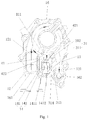
- a barrier wall 41 is disposed between the outflowing buffer chamber 141 and the low-pressure oil chamber 12.
- the rotor mounting part 11 is disposed at an end of the shell 1.
- the high-pressure oil chamber 13, the buffer chamber 14 and the low-pressure oil chamber 12 are located at the same side of the periphery of the rotor mounting part 11.
- the high-pressure oil chamber 13 and the low-pressure oil chamber 12 are disposed side by side at the same side of the periphery the rotor mounting part 11 with the buffer chamber 14 located therebetween.
- the shell 1 comprises a main shell body 15 and a cover 16 fitted with, for example, jointed with the main shell body 15.
- the inlet 161 and the outlet 162 are formed in the cover 16.
- the partition wall 3 comprises a first partition wall portion 31 formed on the cover 16, and a second partition wall portion 32 formed on the main shell body 15.
- the second partition wall portion 32 is corresponding to and fluid-tightly joined with the first partition wall portion 31.
- the buffer chamber 14 in the embodiments of the present disclosure is adapted for releasing the pressure of the oil in the high-pressure oil chamber 13.
- the buffer chamber 14 defined between the high-pressure oil chamber 13 and the low-pressure oil chamber 12, when the oil pressure in the high-pressure oil chamber 13 reaches a predetermined pressure, part of the high-pressure oil (also referred as pressure relief oil hereinafter) in the high-pressure oil chamber 13 flows into the buffer chamber 14, thus releasing the oil pressure in the high-pressure oil chamber 13.
- the buffer chamber 14 by providing the buffer chamber 14, the flowing direction of the pressure relief oil is changed and the flowing speed thereof is reduced, thus stabilizing flowing of the pressure relief oil.
- the pressure relief oil released from the inflowing buffer chamber 142 into outflowing buffer chamber 141 may flow along the barrier wall 41 smoothly and then enter into the low-pressure oil chamber 12, thus avoiding the unnecessary eddy generated by impacting of the pressure relief oil against the low-pressure oil entering the low-pressure oil chamber 12 through the inlet 161, so that the efficiency of the oil pump can be improved.
- the high-pressure oil chamber 13, the buffer chamber 14, and the low-pressure oil chamber 12 are provided at the same side of the periphery of the rotor mounting part 11, so that the oil pump is compact in structure and occupies a small space, which is advantageous for miniaturization of the oil pump as well as the engine having the oil pump.
- one end of the flow limiting wall 42 is connected with a lower portion of the rotor mounting part 111, and the other end of the flow limiting wall 42 is connected with the partition wall 3.
- the mounting part 111, the flow limiting wall 42, and the partition wall 3 define the inflowing buffer chamber 142.
- the flow limiting wall 42, the partition wall 3, and the barrier wall 41 define the outflowing buffer chamber 141.
- a through hole 421 communicating the inflowing buffer chamber 142 and the outflowing buffer chamber 141 is formed in the flow limiting wall 42, and the pressure relief mechanism 6 is disposed in the through hole 421.
- the barrier wall 41 is disposed at a side of the inlet 161 and parallel to an inflowing direction (main flowing direction) of the oil entering into the low-pressure oil chamber 12 through the inlet 161.
- a top end surface of the barrier wall 41 is a circular arc surface, thus facilitating a smooth flowing of the pressure relief oil.
- the low-pressure oil passage 121 and the high-pressure oil passage 131 may be disposed in the cover 16.
- the flow limiting wall 42 may comprise a cover flow limiting wall part 422 and a body flow limiting wall part 423 jointed with the cover flow limiting wall part 422.
- the cover flow limiting wall part 422 is formed on the cover 16, and the body flow limiting wall part 423 is formed on the main shell body 15.
- the through hole 421 communicating the inflowing buffer chamber 142 and the outflowing buffer chamber 141 is formed in the cover flow limiting wall part 422, and the pressure relief mechanism 6 is disposed in the through hole 421.
- the first partition wall portion 31 comprises a first main body portion 311 adjacent to the outlet 162, and a first extending portion 312 extending from the first main body portion 311 to the rotor mounting part 11.
- the second partition wall portion 32 comprises a second main body portion 321 adjacent to the outlet 162, and a second extending portion 322 extending from the second main body portion 321 to the rotor mounting part 11.
- a side (the right side in Fig. 1 ) of the first extending portion 312 and a side (the left side in Fig. 2 ) of the second extending portion 322 facing to the high pressure oil chamber is inclined, so as to facilitate to guide the flowing of the oil in the high-pressure oil chamber 13.
- the inclined sides of the first extending portion 312 and the second extending portion 322 are inclined towards the high-pressure oil chamber 13.
- the first partition wall portion 31 has a first smooth partition surface 313, and the second partition wall portion 32 has a second smooth partition surface 323 joined with the first partition surface 313. Thereby, the first partition wall portion 31 may be joined more tightly with the second partition wall portion 32.
- the first and second partition wall portions 31, 32 each have a bolt hole.
- the bolt hole comprises a first bolt hole portion 314 formed in the first partition wall portion 31 and a second bolt hole portion 324 formed in the second partition wall portion 32 and corresponding to the first bolt hole portion 314.
- the first and second partition wall portions 31, 32 may be secured by a bolt passing through the bolt hole, thus enhancing the joining force between the first partition wall portion 31 and the second partition wall portion 32, and further preventing the oil leakage.
- a plurality of bolt holes may be formed in different positions around the outlet 162. In that way, the joining force between the first partition wall portion 31 and the second partition wall portion 32 may be more uniform. In addition, it is advantageous for isolation between the low-pressure and high-pressure oil chambers 12, 13, and the oil leakage may be further prevented.
- a width of the partition wall 3 is 1.5 to 2 times of a maximum value of a diameter of the bolt hole.
- the bolt hole is formed at an end of the partition wall adjacent to the rotor mounting part 11. In an embodiment, the bolt hole is located in the middle of the partition wall. By way of example and without limiting, the bolt hole is located in the extension portion of the partition wall and at a side adjacent to the rotor mounting part 11. Thereby, the stability of the oil pump may be improved.
- the outflowing buffer chamber 141 may comprise a pressure relief channel adapted to change a flowing direction of the pressure relief oil in the outflowing buffer chamber 141.
- the pressure relief channel may be formed in the cover 16. The pressure relief channel may ensure a fluent flowing of the pressure relief oil along the axial direction of the pressure relief mechanism 6.
- the pressure relief mechanism 6 comprises a relief valve 61, a spring mechanism 62, and a spring base 63, as shown in Fig. 4 .
- the pressure relief channel comprises a first pressure relief port 1411 and a second pressure relief port 1412 disposed symmetrically with each other relative to the center axis of the through hole 421.
- the first and second pressure relief ports 1411, 1412 each have a right-angled trapezoid shaped cross-section.
- the cross-section of the first and second pressure relief ports 1411, 1412 may be configured as other shapes such as circular shape or triangular shape.
- the rotor mechanism 2 comprises an inner rotor 21 and an outer rotor 22.
- the inner rotor 21 is mounted on a rotor shaft.
- a groove 211 is formed in the inner wall of the inner rotor 21, and the inner rotor 21 is mounted on the rotor shaft by a spline or a pin fitted in the groove 211.
- the outer rotor 22 and the inner rotor 21 may be eccentrically disposed relative to each other in the shell 1.
- the rotation of the inner rotor 21 drives the out rotor 22 to rotate.
- the inner rotor 21 has seven teeth
- the outer rotor 22 has eight teeth.
- the inner rotor 21 driven by the rotor shaft may drive the outer rotor 22 to rotate in the same direction but not synchronized with the inner rotor 21.
- the oil pump is more compact in structure, the oil supplying amount is large, the oil supplying is uniform, the noise is reduced and the vacuum degree for pumping oil is increased. Thereby, a circular flowing of the oil in the lubricating system may be ensured.
- the tooth of each of the inner and outer rotors 21, 22 is designed to ensure that the inner and outer rotors 21, 22 are in constant point-contact when the inner and outer rotors 21, 22 rotate to any angle.
- the arrow shows the flowing direction of the oil. Due to disengage of the inner and outer rotors 21, 22, the volume of the low-pressure oil chamber 12 communicated with the inlet 161 is gradually increased, and then a vacuum is generated to suck the oil into the low-pressure oil chamber 12. With the continuing rotation of the rotor mechanism 2, the oil is brought into the side of the rotor mechanism 2 adjacent to the outlet 162. Then, the inner and outer rotors 21, 22 may engage with each other, and the pressure of the oil is increased. In this way, the oil may be pushed out through gaps between the teeth of the inner and outer rotors 21, 22 and flows into the high-pressure oil chamber 13 and the inflowing buffer chamber 142 respectively.
- the oil in the high-pressure oil chamber 13 flows out via the outlet 162.
- the relief valve 61 may be opened and a part of the oil may flow from the inflowing buffer chamber 142 into the outflowing buffer chamber 141.
- the inflowing buffer chamber 142 and the outflowing buffer chamber 141 provide two stages of buffering for the pressure relief oil, so that the flowing direction of the pressure relief oil may be changed, and the pressure and the speed of the pressure relief oil are also reduced.
- the flowing direction of the pressure relief oil in the outflowing buffer chamber 141 is further changed via the pressure relief channel, so that the pressure relief oil may flow more stably. Because the barrier wall 41 is parallel to the flowing direction of the oil flowing into the low-pressure oil chamber 12 via the inlet 161, the pressure relief oil does not apply a greater impact onto the oil in the low-pressure oil chamber 12 when the pressure relief oil is flowing between the barrier wall 41 and the flow limiting wall 42.
- the pressure relief oil together with the oil entering the low-pressure oil chamber 12 via the inlet 162 may enter into a next cycle.
- the partition wall 3 by provision of the partition wall 3, the high-pressure oil chamber 13 and the low-pressure oil chamber 12 are completely separated or isolated or partitioned with each other when the pressure relief valve 61 is closed.
- the pressure loss caused by oil leakage may be prevented, and the efficiency of oil pumping may be further improved.
- the engine cover comprises an oil pump described with reference to the above embodiments.
- the engine cover comprises an engine cover body on which the shell 1 of the oil pump is integrally formed.
- the engine cover such as a front cover of the engine comprises an engine cover body 5, and the shell 1 of the oil pump is integral with the engine cover body 5.
- the engine cover body is integral with the shell 1 of the oil pump, the engine may be simplified in structure, and the maintenance of the oil pump may be convenient.
- an engine comprising the engine cover described with reference to the above embodiments.
- the engine comprises a cylinder cover, an engine cylinder block connected with a lower end of the cylinder cover, and an engine cover disposed at a front end of the cylinder cover and the engine cylinder block.
- a lower end of the engine cylinder block is connected with the shell 1 of the oil pump.
- the engine cover comprises an engine cover body 5, and the shell 1 of the oil pump is integral with the engine cover body 5.
Landscapes
- Engineering & Computer Science (AREA)
- Mechanical Engineering (AREA)
- General Engineering & Computer Science (AREA)
- Rotary Pumps (AREA)
- Details And Applications Of Rotary Liquid Pumps (AREA)
Claims (14)
- Eine Ölpumpe, aufweisend:eine Schale (1), die einen Einlass (161) und einen Auslass (162) aufweist und eine Niederdruckölkammer (12) und eine Hochdruckölkammer (13) darin definiert, wobei die Niederdruckölkammer (12) einen Niederdruckölkanal (121), der mit dem Einlass (161) in Verbindung steht, aufweist und die Hochdruckölkammer (13) einen Hochdruckölkanal (131), der mit dem Auslass (162) in Verbindung steht, aufweist;einen Rotorbefestigungsteil (11), der auf der Schale (1) angeordnet ist und eine Rotortragstruktur (111) aufweist; undeinen Rotormechanismus (2), der auf dem Rotorbefestigungsteil (11) angeordnet ist; und wobeieine Trennwand (3) zwischen der Niederdruckölkammer (12) und der Hochdruckölkammer (13) angeordnet ist, um die Niederdruckölkammer (12) und der Hochdruckölkammer (13) voneinander abzuteilen, undeine Pufferkammer (14) zwischen der Trennwand (3) und der Niederdruckölkammer (12) definiert ist und eine den Durchfluss begrenzende Wand in der Pufferkammer (14) angeordnet ist,dadurch gekennzeichnet, dassdie den Durchfluss begrenzende Wand die Pufferkammer (14) in eine Einström-Pufferkammer (142) und eine Ausström-Pufferkammer (141), die mit der Einström-Pufferkammer (142) über einen Druckentlastungsmechanismus (6) in Verbindung steht, teilt, wobei die Einström-Pufferkammer (142) mit der Hochdruckölkammer (13) in Verbindung steht und die Ausström-Pufferkammer (141) mit der Niederdruckölkammer (12) in Verbindung steht.
- Die Ölpumpe nach Anspruch 1, wobei die Trennwand (3) aufweist:einen Hauptkörperabschnitt (311) benachbart zum Auslass (162), undeinen Erstreckungsabschnitt (312), der sich vom Hauptkörperabschnitt (311) zum Rotorbefestigungsteil (11) erstreckt.
- Die Ölpumpe nach Anspruch 2, wobei eine Seite des Erstreckungsabschnitts (312), die der Hochdruckölkammer (13) zugewandt ist, geneigt ist.
- Die Ölpumpe nach einem der Ansprüche 1 bis 3, wobei die Schale (1) einen Schalenhauptkörper (15) und eine Abdeckung (16), die gelenkig mit dem Schalenhauptkörper (15) verbunden ist, aufweist,
wobei die Trennwand (3) einen ersten Trennwandabschnitt (31), der auf der Abdeckung (16) ausgebildet ist, und einen zweiten Trennwandabschnitt (32), der auf dem Schalenhauptkörper (15) ausgebildet ist und mit dem ersten Trennwandabschnitt (31) korrespondiert und fluiddicht mit diesem verbunden ist, aufweist. - Die Ölpumpe nach Anspruch 4, wobei der erste Trennwandabschnitt (31) eine erste glatte Trennoberfläche aufweist und der zweite Trennwandabschnitt (32) eine zweite glatte Trennoberfläche, die mit der ersten Trennoberfläche verbunden ist, aufweist.
- Die Ölpumpe nach Anspruch 4, wobei die Trennwand (3) ein Bolzenloch, das einen ersten Bolzenlochabschnitt (314), der im ersten Trennwandabschnitt (31) ausgebildet ist, und einen zweiten Bolzenlochabschnitt (324), der im zweiten Trennwandabschnitt (32) ausgebildet ist und mit dem ersten Bolzenlochabschnitt (314) korrespondiert, aufweist.
- Die Ölpumpe nach Anspruch 6, wobei das Bolzenloch an einem Ende der Trennwand (3) benachbart zum Rotorbefestigungsteil (11) ausgebildet ist und wobei eine Breite der Trennwand (3) 1,5 bis 2mal einem Höchstwert eines Durchmessers des Bolzenlochs entspricht.
- Die Ölpumpe nach einem der Ansprüche 1 bis 7, wobei der Rotorbefestigungsteil (11) an einem Ende der Schale (1) angeordnet ist und die Hochdruckölkammer (13) und die Niederdruckölkammer (12) nebeneinander auf derselben Seite eines Umfangs des Rotorbefestigungsteils (11) angeordnet sind.
- Die Ölpumpe nach Anspruch 1, wobei der Rotorbefestigungsteil (11) an einem Ende der Schale (1) angeordnet ist und die Hochdruckölkammer (13), die Pufferkammer (14) und die Niederdruckölkammer (12) auf derselben Seite des Rotorbefestigungsteils (11) angeordnet sind.
- Die Ölpumpe nach Anspruch 9, wobei ein Ende der den Durchfluss begrenzenden Wand mit einem unteren Abschnitt des Rotorbefestigungsteils (11) verbunden ist und das andere Ende der den Durchfluss begrenzenden Wand mit der Trennwand (3) verbunden ist.
- Die Ölpumpe nach einem der Ansprüche 9 oder 10, wobei ein Durchgangsloch, das die Einström-Pufferkammer (142) und die Ausström-Pufferkammer (141) miteinander verbindet, in der den Durchfluss begrenzenden Wand ausgebildet ist, und wobei der Druckentlastungsmechanismus (6) im Durchgangsloch angeordnet ist.
- Die Ölpumpe nach einem der Ansprüche 9 bis 11, wobei eine Sperrwand (41) zwischen der Ausström-Pufferkammer (141) und der Niederdruckölkammer (12) angeordnet ist, und wobei die Sperrwand (14) auf einer Seite des Einlasses (161) und parallel zu einer Einströmrichtung eines Öls, das durch den Einlass (161) in die Niederdruckölkammer (12) strömt, angeordnet ist.
- Eine Motorabdeckung, aufweisend:einen Motorabdeckungskörper (5), undeine Ölpumpe nach einem der Ansprüche 1-12, die auf dem Motorabdeckungskörper (5) angeordnet ist, wobei die Schale (1) der Ölpumpe einstückig mit dem Motorabdeckungskörper (5) ausgebildet ist.
- Ein Motor, aufweisend eine Motorabdeckung nach Anspruch 13.
Applications Claiming Priority (3)
| Application Number | Priority Date | Filing Date | Title |
|---|---|---|---|
| CN 201220124124 CN202596832U (zh) | 2012-03-29 | 2012-03-29 | 一种机油泵、发动机前罩盖以及发动机 |
| CN201210087044.3A CN103363277B (zh) | 2012-03-29 | 2012-03-29 | 一种机油泵、发动机前罩盖以及发动机 |
| PCT/CN2013/073354 WO2013143476A1 (en) | 2012-03-29 | 2013-03-28 | Oil pump, engine cover and engine comprising the same |
Publications (3)
| Publication Number | Publication Date |
|---|---|
| EP2834485A1 EP2834485A1 (de) | 2015-02-11 |
| EP2834485A4 EP2834485A4 (de) | 2015-11-18 |
| EP2834485B1 true EP2834485B1 (de) | 2018-01-31 |
Family
ID=49258233
Family Applications (1)
| Application Number | Title | Priority Date | Filing Date |
|---|---|---|---|
| EP13768663.0A Active EP2834485B1 (de) | 2012-03-29 | 2013-03-28 | Ölpumpe, motorabdeckung und motor damit |
Country Status (3)
| Country | Link |
|---|---|
| US (1) | US9869313B2 (de) |
| EP (1) | EP2834485B1 (de) |
| WO (1) | WO2013143476A1 (de) |
Families Citing this family (3)
| Publication number | Priority date | Publication date | Assignee | Title |
|---|---|---|---|---|
| US10895257B2 (en) * | 2018-02-13 | 2021-01-19 | GM Global Technology Operations LLC | Lubrication strategy for dry run pump system |
| CN108412631B (zh) * | 2018-05-17 | 2023-08-15 | 鼎欣吉盛科技(浙江)有限公司 | 一种带有机油泵的正时链罩 |
| USD976284S1 (en) * | 2020-08-21 | 2023-01-24 | Holley Performance Products, Inc. | Timing cover |
Family Cites Families (30)
| Publication number | Priority date | Publication date | Assignee | Title |
|---|---|---|---|---|
| CA2029609C (en) * | 1990-11-13 | 1995-01-03 | Eric Cozens | Pulse tuned optimized positive displacement porting |
| JP3189302B2 (ja) * | 1991-07-16 | 2001-07-16 | スズキ株式会社 | 船外機のオイルポンプ |
| JP3136666B2 (ja) * | 1991-07-26 | 2001-02-19 | スズキ株式会社 | 船外機のオイルポンプ |
| JPH08100620A (ja) | 1994-09-30 | 1996-04-16 | Suzuki Motor Corp | エンジンの潤滑装置 |
| JP2824413B2 (ja) | 1996-01-26 | 1998-11-11 | 川崎重工業株式会社 | オイルポンプ |
| DE19646359C2 (de) | 1996-11-09 | 2001-12-06 | Gkn Sinter Metals Gmbh | Schmierölpumpe mit einem Verzahnungsrotorsatz |
| JP4218056B2 (ja) | 1999-01-29 | 2009-02-04 | マツダ株式会社 | オイルポンプ |
| JP3643311B2 (ja) | 2000-03-03 | 2005-04-27 | 本田技研工業株式会社 | リリーフ弁構造 |
| KR100444483B1 (ko) * | 2002-11-21 | 2004-08-16 | 현대자동차주식회사 | 차량의 밸랜스 샤프트 모듈 타입 오일펌프 |
| JP4224378B2 (ja) * | 2003-11-04 | 2009-02-12 | 株式会社日立製作所 | オイルポンプ |
| US7559754B2 (en) | 2005-06-23 | 2009-07-14 | Kawasaki Jukogyo Kabushiki Kaisha | Internal gear pump in combustion engine |
| US7174875B2 (en) * | 2005-07-01 | 2007-02-13 | Harley-Davidson Motor Company Group, Inc. | Primary housing assembly for a motorcycle engine |
| US20070092392A1 (en) | 2005-10-20 | 2007-04-26 | Aisin Seiki Kabushiki Kaisha | Internal gear pump |
| CN201066030Y (zh) | 2007-07-13 | 2008-05-28 | 四机赛瓦石油钻采设备有限公司 | 一种润滑油泵 |
| CN201087731Y (zh) * | 2007-07-21 | 2008-07-16 | 奇瑞汽车有限公司 | 汽车发动机转子式机油泵 |
| CN201372923Y (zh) | 2009-04-03 | 2009-12-30 | 王新宽 | 带泄压装置的单缸柴油机机油泵 |
| CN101629500B (zh) | 2009-07-31 | 2011-09-21 | 奇瑞汽车股份有限公司 | 一种发动机机油压力调节装置 |
| JP5215959B2 (ja) | 2009-08-06 | 2013-06-19 | 本田技研工業株式会社 | オイルポンプのリリーフ弁 |
| CN201723266U (zh) | 2010-06-18 | 2011-01-26 | 上海幸福摩托车有限公司 | 用于汽车发动机的机油泵 |
| CN201778850U (zh) | 2010-06-18 | 2011-03-30 | 上海幸福摩托车有限公司 | 汽车发动机机油泵 |
| CN101865003B (zh) | 2010-06-18 | 2012-02-01 | 上海幸福摩托车有限公司 | 汽车发动机机油泵 |
| CN201738961U (zh) | 2010-06-30 | 2011-02-09 | 长城汽车股份有限公司 | 一种横置柴油发动机的机油泵 |
| CN201771570U (zh) | 2010-06-30 | 2011-03-23 | 上海通用汽车有限公司 | 内燃机润滑油路布置系统 |
| JP5591049B2 (ja) | 2010-09-30 | 2014-09-17 | 富士重工業株式会社 | 内接歯車式流体装置 |
| CN201892018U (zh) * | 2010-11-25 | 2011-07-06 | 湖南机油泵股份有限公司 | 回流限压转子机油泵 |
| CN102364205A (zh) | 2011-10-24 | 2012-02-29 | 上海幸福摩托车有限公司 | 可变排量机油泵 |
| CN202596832U (zh) * | 2012-03-29 | 2012-12-12 | 比亚迪股份有限公司 | 一种机油泵、发动机前罩盖以及发动机 |
| CN202546211U (zh) * | 2012-03-29 | 2012-11-21 | 比亚迪股份有限公司 | 一种机油泵、发动机前罩盖以及发动机 |
| CN202596831U (zh) * | 2012-03-29 | 2012-12-12 | 比亚迪股份有限公司 | 一种机油泵、发动机前罩盖以及发动机 |
| CN202546203U (zh) * | 2012-03-29 | 2012-11-21 | 比亚迪股份有限公司 | 一种机油泵、发动机前罩盖以及发动机 |
-
2013
- 2013-03-28 EP EP13768663.0A patent/EP2834485B1/de active Active
- 2013-03-28 US US14/380,052 patent/US9869313B2/en active Active
- 2013-03-28 WO PCT/CN2013/073354 patent/WO2013143476A1/en not_active Ceased
Non-Patent Citations (1)
| Title |
|---|
| None * |
Also Published As
| Publication number | Publication date |
|---|---|
| EP2834485A4 (de) | 2015-11-18 |
| US9869313B2 (en) | 2018-01-16 |
| US20150322942A1 (en) | 2015-11-12 |
| EP2834485A1 (de) | 2015-02-11 |
| WO2013143476A1 (en) | 2013-10-03 |
Similar Documents
| Publication | Publication Date | Title |
|---|---|---|
| EP3828415B1 (de) | Interne getriebepumpe | |
| JP2015140659A (ja) | ベーンポンプ | |
| US20150167665A1 (en) | Multistage oil pump | |
| JP5400215B2 (ja) | 油圧ポンプ・モータおよび油圧ポンプ・モータの脈動防止方法 | |
| EP2831487B1 (de) | Ölpumpe, motorabdeckung und motor damit | |
| KR20140033307A (ko) | 이중 배출 펌프 | |
| US9869313B2 (en) | Oil pump, engine cover and engine comprising the same | |
| JP5009760B2 (ja) | 内接歯車ポンプ | |
| US20150118087A1 (en) | Multistage oil pump | |
| EP2831488B1 (de) | Ölpumpe, motorabdeckung und motor damit | |
| JP2017089396A (ja) | ベーンポンプ | |
| JP2014122558A (ja) | ベーンポンプ | |
| US20130034460A1 (en) | Variable Displacement Vane Pump | |
| JP5357574B2 (ja) | 内接歯車ポンプ | |
| US20200392847A1 (en) | Vane pump | |
| JP5469875B2 (ja) | 内接歯車ポンプ | |
| US20020051721A1 (en) | Vane pump | |
| CN109923313B (zh) | 叶片泵 | |
| JP2015175281A (ja) | 圧縮機 | |
| EP1970570B1 (de) | Innenzahnradpumpe | |
| KR20160065425A (ko) | 2중 노치가 형성된 베인 펌프 | |
| JP5540925B2 (ja) | ベーンポンプ | |
| KR102529520B1 (ko) | 차량용 진공펌프 | |
| JP6042969B2 (ja) | ベーンポンプ | |
| JP7857170B2 (ja) | 内接ギヤポンプ |
Legal Events
| Date | Code | Title | Description |
|---|---|---|---|
| PUAI | Public reference made under article 153(3) epc to a published international application that has entered the european phase |
Free format text: ORIGINAL CODE: 0009012 |
|
| 17P | Request for examination filed |
Effective date: 20140908 |
|
| AK | Designated contracting states |
Kind code of ref document: A1 Designated state(s): AL AT BE BG CH CY CZ DE DK EE ES FI FR GB GR HR HU IE IS IT LI LT LU LV MC MK MT NL NO PL PT RO RS SE SI SK SM TR |
|
| AX | Request for extension of the european patent |
Extension state: BA ME |
|
| DAX | Request for extension of the european patent (deleted) | ||
| RA4 | Supplementary search report drawn up and despatched (corrected) |
Effective date: 20151016 |
|
| RIC1 | Information provided on ipc code assigned before grant |
Ipc: F16N 13/20 20060101ALI20151012BHEP Ipc: F01M 1/02 20060101AFI20151012BHEP |
|
| STAA | Information on the status of an ep patent application or granted ep patent |
Free format text: STATUS: EXAMINATION IS IN PROGRESS |
|
| 17Q | First examination report despatched |
Effective date: 20161213 |
|
| GRAP | Despatch of communication of intention to grant a patent |
Free format text: ORIGINAL CODE: EPIDOSNIGR1 |
|
| STAA | Information on the status of an ep patent application or granted ep patent |
Free format text: STATUS: GRANT OF PATENT IS INTENDED |
|
| INTG | Intention to grant announced |
Effective date: 20170926 |
|
| GRAS | Grant fee paid |
Free format text: ORIGINAL CODE: EPIDOSNIGR3 |
|
| GRAA | (expected) grant |
Free format text: ORIGINAL CODE: 0009210 |
|
| STAA | Information on the status of an ep patent application or granted ep patent |
Free format text: STATUS: THE PATENT HAS BEEN GRANTED |
|
| AK | Designated contracting states |
Kind code of ref document: B1 Designated state(s): AL AT BE BG CH CY CZ DE DK EE ES FI FR GB GR HR HU IE IS IT LI LT LU LV MC MK MT NL NO PL PT RO RS SE SI SK SM TR |
|
| REG | Reference to a national code |
Ref country code: GB Ref legal event code: FG4D Ref country code: CH Ref legal event code: EP |
|
| REG | Reference to a national code |
Ref country code: AT Ref legal event code: REF Ref document number: 967609 Country of ref document: AT Kind code of ref document: T Effective date: 20180215 |
|
| REG | Reference to a national code |
Ref country code: IE Ref legal event code: FG4D |
|
| REG | Reference to a national code |
Ref country code: DE Ref legal event code: R096 Ref document number: 602013032653 Country of ref document: DE |
|
| REG | Reference to a national code |
Ref country code: FR Ref legal event code: PLFP Year of fee payment: 6 |
|
| REG | Reference to a national code |
Ref country code: NL Ref legal event code: MP Effective date: 20180131 |
|
| REG | Reference to a national code |
Ref country code: LT Ref legal event code: MG4D |
|
| REG | Reference to a national code |
Ref country code: AT Ref legal event code: MK05 Ref document number: 967609 Country of ref document: AT Kind code of ref document: T Effective date: 20180131 |
|
| PG25 | Lapsed in a contracting state [announced via postgrant information from national office to epo] |
Ref country code: NO Free format text: LAPSE BECAUSE OF FAILURE TO SUBMIT A TRANSLATION OF THE DESCRIPTION OR TO PAY THE FEE WITHIN THE PRESCRIBED TIME-LIMIT Effective date: 20180430 Ref country code: ES Free format text: LAPSE BECAUSE OF FAILURE TO SUBMIT A TRANSLATION OF THE DESCRIPTION OR TO PAY THE FEE WITHIN THE PRESCRIBED TIME-LIMIT Effective date: 20180131 Ref country code: NL Free format text: LAPSE BECAUSE OF FAILURE TO SUBMIT A TRANSLATION OF THE DESCRIPTION OR TO PAY THE FEE WITHIN THE PRESCRIBED TIME-LIMIT Effective date: 20180131 Ref country code: FI Free format text: LAPSE BECAUSE OF FAILURE TO SUBMIT A TRANSLATION OF THE DESCRIPTION OR TO PAY THE FEE WITHIN THE PRESCRIBED TIME-LIMIT Effective date: 20180131 Ref country code: LT Free format text: LAPSE BECAUSE OF FAILURE TO SUBMIT A TRANSLATION OF THE DESCRIPTION OR TO PAY THE FEE WITHIN THE PRESCRIBED TIME-LIMIT Effective date: 20180131 Ref country code: HR Free format text: LAPSE BECAUSE OF FAILURE TO SUBMIT A TRANSLATION OF THE DESCRIPTION OR TO PAY THE FEE WITHIN THE PRESCRIBED TIME-LIMIT Effective date: 20180131 |
|
| PG25 | Lapsed in a contracting state [announced via postgrant information from national office to epo] |
Ref country code: BG Free format text: LAPSE BECAUSE OF FAILURE TO SUBMIT A TRANSLATION OF THE DESCRIPTION OR TO PAY THE FEE WITHIN THE PRESCRIBED TIME-LIMIT Effective date: 20180430 Ref country code: AT Free format text: LAPSE BECAUSE OF FAILURE TO SUBMIT A TRANSLATION OF THE DESCRIPTION OR TO PAY THE FEE WITHIN THE PRESCRIBED TIME-LIMIT Effective date: 20180131 Ref country code: GR Free format text: LAPSE BECAUSE OF FAILURE TO SUBMIT A TRANSLATION OF THE DESCRIPTION OR TO PAY THE FEE WITHIN THE PRESCRIBED TIME-LIMIT Effective date: 20180501 Ref country code: PL Free format text: LAPSE BECAUSE OF FAILURE TO SUBMIT A TRANSLATION OF THE DESCRIPTION OR TO PAY THE FEE WITHIN THE PRESCRIBED TIME-LIMIT Effective date: 20180131 Ref country code: RS Free format text: LAPSE BECAUSE OF FAILURE TO SUBMIT A TRANSLATION OF THE DESCRIPTION OR TO PAY THE FEE WITHIN THE PRESCRIBED TIME-LIMIT Effective date: 20180131 Ref country code: LV Free format text: LAPSE BECAUSE OF FAILURE TO SUBMIT A TRANSLATION OF THE DESCRIPTION OR TO PAY THE FEE WITHIN THE PRESCRIBED TIME-LIMIT Effective date: 20180131 Ref country code: SE Free format text: LAPSE BECAUSE OF FAILURE TO SUBMIT A TRANSLATION OF THE DESCRIPTION OR TO PAY THE FEE WITHIN THE PRESCRIBED TIME-LIMIT Effective date: 20180131 Ref country code: IS Free format text: LAPSE BECAUSE OF FAILURE TO SUBMIT A TRANSLATION OF THE DESCRIPTION OR TO PAY THE FEE WITHIN THE PRESCRIBED TIME-LIMIT Effective date: 20180531 |
|
| PG25 | Lapsed in a contracting state [announced via postgrant information from national office to epo] |
Ref country code: RO Free format text: LAPSE BECAUSE OF FAILURE TO SUBMIT A TRANSLATION OF THE DESCRIPTION OR TO PAY THE FEE WITHIN THE PRESCRIBED TIME-LIMIT Effective date: 20180131 Ref country code: IT Free format text: LAPSE BECAUSE OF FAILURE TO SUBMIT A TRANSLATION OF THE DESCRIPTION OR TO PAY THE FEE WITHIN THE PRESCRIBED TIME-LIMIT Effective date: 20180131 Ref country code: EE Free format text: LAPSE BECAUSE OF FAILURE TO SUBMIT A TRANSLATION OF THE DESCRIPTION OR TO PAY THE FEE WITHIN THE PRESCRIBED TIME-LIMIT Effective date: 20180131 Ref country code: AL Free format text: LAPSE BECAUSE OF FAILURE TO SUBMIT A TRANSLATION OF THE DESCRIPTION OR TO PAY THE FEE WITHIN THE PRESCRIBED TIME-LIMIT Effective date: 20180131 |
|
| REG | Reference to a national code |
Ref country code: CH Ref legal event code: PL |
|
| REG | Reference to a national code |
Ref country code: DE Ref legal event code: R097 Ref document number: 602013032653 Country of ref document: DE |
|
| PG25 | Lapsed in a contracting state [announced via postgrant information from national office to epo] |
Ref country code: MC Free format text: LAPSE BECAUSE OF FAILURE TO SUBMIT A TRANSLATION OF THE DESCRIPTION OR TO PAY THE FEE WITHIN THE PRESCRIBED TIME-LIMIT Effective date: 20180131 Ref country code: SM Free format text: LAPSE BECAUSE OF FAILURE TO SUBMIT A TRANSLATION OF THE DESCRIPTION OR TO PAY THE FEE WITHIN THE PRESCRIBED TIME-LIMIT Effective date: 20180131 Ref country code: DK Free format text: LAPSE BECAUSE OF FAILURE TO SUBMIT A TRANSLATION OF THE DESCRIPTION OR TO PAY THE FEE WITHIN THE PRESCRIBED TIME-LIMIT Effective date: 20180131 Ref country code: CZ Free format text: LAPSE BECAUSE OF FAILURE TO SUBMIT A TRANSLATION OF THE DESCRIPTION OR TO PAY THE FEE WITHIN THE PRESCRIBED TIME-LIMIT Effective date: 20180131 Ref country code: SK Free format text: LAPSE BECAUSE OF FAILURE TO SUBMIT A TRANSLATION OF THE DESCRIPTION OR TO PAY THE FEE WITHIN THE PRESCRIBED TIME-LIMIT Effective date: 20180131 |
|
| PLBE | No opposition filed within time limit |
Free format text: ORIGINAL CODE: 0009261 |
|
| STAA | Information on the status of an ep patent application or granted ep patent |
Free format text: STATUS: NO OPPOSITION FILED WITHIN TIME LIMIT |
|
| REG | Reference to a national code |
Ref country code: BE Ref legal event code: MM Effective date: 20180331 |
|
| REG | Reference to a national code |
Ref country code: IE Ref legal event code: MM4A |
|
| PG25 | Lapsed in a contracting state [announced via postgrant information from national office to epo] |
Ref country code: LU Free format text: LAPSE BECAUSE OF NON-PAYMENT OF DUE FEES Effective date: 20180328 |
|
| 26N | No opposition filed |
Effective date: 20181102 |
|
| PG25 | Lapsed in a contracting state [announced via postgrant information from national office to epo] |
Ref country code: IE Free format text: LAPSE BECAUSE OF NON-PAYMENT OF DUE FEES Effective date: 20180328 |
|
| PG25 | Lapsed in a contracting state [announced via postgrant information from national office to epo] |
Ref country code: BE Free format text: LAPSE BECAUSE OF NON-PAYMENT OF DUE FEES Effective date: 20180331 Ref country code: SI Free format text: LAPSE BECAUSE OF FAILURE TO SUBMIT A TRANSLATION OF THE DESCRIPTION OR TO PAY THE FEE WITHIN THE PRESCRIBED TIME-LIMIT Effective date: 20180131 Ref country code: LI Free format text: LAPSE BECAUSE OF NON-PAYMENT OF DUE FEES Effective date: 20180331 Ref country code: CH Free format text: LAPSE BECAUSE OF NON-PAYMENT OF DUE FEES Effective date: 20180331 |
|
| PG25 | Lapsed in a contracting state [announced via postgrant information from national office to epo] |
Ref country code: MT Free format text: LAPSE BECAUSE OF NON-PAYMENT OF DUE FEES Effective date: 20180328 |
|
| PG25 | Lapsed in a contracting state [announced via postgrant information from national office to epo] |
Ref country code: TR Free format text: LAPSE BECAUSE OF FAILURE TO SUBMIT A TRANSLATION OF THE DESCRIPTION OR TO PAY THE FEE WITHIN THE PRESCRIBED TIME-LIMIT Effective date: 20180131 |
|
| REG | Reference to a national code |
Ref country code: DE Ref legal event code: R081 Ref document number: 602013032653 Country of ref document: DE Owner name: BYD COMPANY LIMITED, SHENZHEN, CN Free format text: FORMER OWNERS: BYD COMPANY LIMITED, SHENZHEN, GUANGDONG, CN; SHENZHEN BYD AUTO R&D COMPANY LIMITED, SHENZHEN, GUANGDONG, CN |
|
| PG25 | Lapsed in a contracting state [announced via postgrant information from national office to epo] |
Ref country code: PT Free format text: LAPSE BECAUSE OF FAILURE TO SUBMIT A TRANSLATION OF THE DESCRIPTION OR TO PAY THE FEE WITHIN THE PRESCRIBED TIME-LIMIT Effective date: 20180131 |
|
| PG25 | Lapsed in a contracting state [announced via postgrant information from national office to epo] |
Ref country code: MK Free format text: LAPSE BECAUSE OF NON-PAYMENT OF DUE FEES Effective date: 20180131 Ref country code: CY Free format text: LAPSE BECAUSE OF FAILURE TO SUBMIT A TRANSLATION OF THE DESCRIPTION OR TO PAY THE FEE WITHIN THE PRESCRIBED TIME-LIMIT Effective date: 20180131 Ref country code: HU Free format text: LAPSE BECAUSE OF FAILURE TO SUBMIT A TRANSLATION OF THE DESCRIPTION OR TO PAY THE FEE WITHIN THE PRESCRIBED TIME-LIMIT; INVALID AB INITIO Effective date: 20130328 |
|
| P01 | Opt-out of the competence of the unified patent court (upc) registered |
Effective date: 20230527 |
|
| PGFP | Annual fee paid to national office [announced via postgrant information from national office to epo] |
Ref country code: GB Payment date: 20260324 Year of fee payment: 14 |
|
| PGFP | Annual fee paid to national office [announced via postgrant information from national office to epo] |
Ref country code: DE Payment date: 20260319 Year of fee payment: 14 |
|
| PGFP | Annual fee paid to national office [announced via postgrant information from national office to epo] |
Ref country code: FR Payment date: 20260320 Year of fee payment: 14 |