EP2834324B1 - Verfahren zur trennung von olefinen bei milder spaltung - Google Patents
Verfahren zur trennung von olefinen bei milder spaltung Download PDFInfo
- Publication number
- EP2834324B1 EP2834324B1 EP13716729.2A EP13716729A EP2834324B1 EP 2834324 B1 EP2834324 B1 EP 2834324B1 EP 13716729 A EP13716729 A EP 13716729A EP 2834324 B1 EP2834324 B1 EP 2834324B1
- Authority
- EP
- European Patent Office
- Prior art keywords
- fraction
- liquid
- scrubbing column
- water
- column
- Prior art date
- Legal status (The legal status is an assumption and is not a legal conclusion. Google has not performed a legal analysis and makes no representation as to the accuracy of the status listed.)
- Active
Links
Images

Classifications
-
- C—CHEMISTRY; METALLURGY
- C07—ORGANIC CHEMISTRY
- C07C—ACYCLIC OR CARBOCYCLIC COMPOUNDS
- C07C7/00—Purification; Separation; Use of additives
- C07C7/11—Purification; Separation; Use of additives by absorption, i.e. purification or separation of gaseous hydrocarbons with the aid of liquids
-
- B—PERFORMING OPERATIONS; TRANSPORTING
- B01—PHYSICAL OR CHEMICAL PROCESSES OR APPARATUS IN GENERAL
- B01D—SEPARATION
- B01D53/00—Separation of gases or vapours; Recovering vapours of volatile solvents from gases; Chemical or biological purification of waste gases, e.g. engine exhaust gases, smoke, fumes, flue gases, aerosols
- B01D53/14—Separation of gases or vapours; Recovering vapours of volatile solvents from gases; Chemical or biological purification of waste gases, e.g. engine exhaust gases, smoke, fumes, flue gases, aerosols by absorption
- B01D53/1406—Multiple stage absorption
-
- B—PERFORMING OPERATIONS; TRANSPORTING
- B01—PHYSICAL OR CHEMICAL PROCESSES OR APPARATUS IN GENERAL
- B01D—SEPARATION
- B01D53/00—Separation of gases or vapours; Recovering vapours of volatile solvents from gases; Chemical or biological purification of waste gases, e.g. engine exhaust gases, smoke, fumes, flue gases, aerosols
- B01D53/14—Separation of gases or vapours; Recovering vapours of volatile solvents from gases; Chemical or biological purification of waste gases, e.g. engine exhaust gases, smoke, fumes, flue gases, aerosols by absorption
- B01D53/1487—Removing organic compounds
-
- B—PERFORMING OPERATIONS; TRANSPORTING
- B01—PHYSICAL OR CHEMICAL PROCESSES OR APPARATUS IN GENERAL
- B01D—SEPARATION
- B01D53/00—Separation of gases or vapours; Recovering vapours of volatile solvents from gases; Chemical or biological purification of waste gases, e.g. engine exhaust gases, smoke, fumes, flue gases, aerosols
- B01D53/14—Separation of gases or vapours; Recovering vapours of volatile solvents from gases; Chemical or biological purification of waste gases, e.g. engine exhaust gases, smoke, fumes, flue gases, aerosols by absorption
- B01D53/18—Absorbing units; Liquid distributors therefor
-
- B—PERFORMING OPERATIONS; TRANSPORTING
- B01—PHYSICAL OR CHEMICAL PROCESSES OR APPARATUS IN GENERAL
- B01J—CHEMICAL OR PHYSICAL PROCESSES, e.g. CATALYSIS OR COLLOID CHEMISTRY; THEIR RELEVANT APPARATUS
- B01J19/00—Chemical, physical or physico-chemical processes in general; Their relevant apparatus
- B01J19/24—Stationary reactors without moving elements inside
-
- C—CHEMISTRY; METALLURGY
- C07—ORGANIC CHEMISTRY
- C07C—ACYCLIC OR CARBOCYCLIC COMPOUNDS
- C07C11/00—Aliphatic unsaturated hydrocarbons
- C07C11/02—Alkenes
- C07C11/04—Ethylene
-
- C—CHEMISTRY; METALLURGY
- C07—ORGANIC CHEMISTRY
- C07C—ACYCLIC OR CARBOCYCLIC COMPOUNDS
- C07C11/00—Aliphatic unsaturated hydrocarbons
- C07C11/02—Alkenes
- C07C11/06—Propene
-
- C—CHEMISTRY; METALLURGY
- C07—ORGANIC CHEMISTRY
- C07C—ACYCLIC OR CARBOCYCLIC COMPOUNDS
- C07C4/00—Preparation of hydrocarbons from hydrocarbons containing a larger number of carbon atoms
- C07C4/02—Preparation of hydrocarbons from hydrocarbons containing a larger number of carbon atoms by cracking a single hydrocarbon or a mixture of individually defined hydrocarbons or a normally gaseous hydrocarbon fraction
- C07C4/04—Thermal processes
-
- C—CHEMISTRY; METALLURGY
- C10—PETROLEUM, GAS OR COKE INDUSTRIES; TECHNICAL GASES CONTAINING CARBON MONOXIDE; FUELS; LUBRICANTS; PEAT
- C10G—CRACKING HYDROCARBON OILS; PRODUCTION OF LIQUID HYDROCARBON MIXTURES, e.g. BY DESTRUCTIVE HYDROGENATION, OLIGOMERISATION, POLYMERISATION; RECOVERY OF HYDROCARBON OILS FROM OIL-SHALE, OIL-SAND, OR GASES; REFINING MIXTURES MAINLY CONSISTING OF HYDROCARBONS; REFORMING OF NAPHTHA; MINERAL WAXES
- C10G9/00—Thermal non-catalytic cracking, in the absence of hydrogen, of hydrocarbon oils
- C10G9/34—Thermal non-catalytic cracking, in the absence of hydrogen, of hydrocarbon oils by direct contact with inert preheated fluids, e.g. with molten metals or salts
- C10G9/36—Thermal non-catalytic cracking, in the absence of hydrogen, of hydrocarbon oils by direct contact with inert preheated fluids, e.g. with molten metals or salts with heated gases or vapours
-
- B—PERFORMING OPERATIONS; TRANSPORTING
- B01—PHYSICAL OR CHEMICAL PROCESSES OR APPARATUS IN GENERAL
- B01J—CHEMICAL OR PHYSICAL PROCESSES, e.g. CATALYSIS OR COLLOID CHEMISTRY; THEIR RELEVANT APPARATUS
- B01J2219/00—Chemical, physical or physico-chemical processes in general; Their relevant apparatus
- B01J2219/24—Stationary reactors without moving elements inside
-
- C—CHEMISTRY; METALLURGY
- C10—PETROLEUM, GAS OR COKE INDUSTRIES; TECHNICAL GASES CONTAINING CARBON MONOXIDE; FUELS; LUBRICANTS; PEAT
- C10G—CRACKING HYDROCARBON OILS; PRODUCTION OF LIQUID HYDROCARBON MIXTURES, e.g. BY DESTRUCTIVE HYDROGENATION, OLIGOMERISATION, POLYMERISATION; RECOVERY OF HYDROCARBON OILS FROM OIL-SHALE, OIL-SAND, OR GASES; REFINING MIXTURES MAINLY CONSISTING OF HYDROCARBONS; REFORMING OF NAPHTHA; MINERAL WAXES
- C10G2400/00—Products obtained by processes covered by groups C10G9/00 - C10G69/14
- C10G2400/20—C2-C4 olefins
-
- Y—GENERAL TAGGING OF NEW TECHNOLOGICAL DEVELOPMENTS; GENERAL TAGGING OF CROSS-SECTIONAL TECHNOLOGIES SPANNING OVER SEVERAL SECTIONS OF THE IPC; TECHNICAL SUBJECTS COVERED BY FORMER USPC CROSS-REFERENCE ART COLLECTIONS [XRACs] AND DIGESTS
- Y02—TECHNOLOGIES OR APPLICATIONS FOR MITIGATION OR ADAPTATION AGAINST CLIMATE CHANGE
- Y02P—CLIMATE CHANGE MITIGATION TECHNOLOGIES IN THE PRODUCTION OR PROCESSING OF GOODS
- Y02P30/00—Technologies relating to oil refining and petrochemical industry
- Y02P30/40—Ethylene production
Definitions
- the invention relates to a process for the production of olefins, wherein a particular liquid hydrocarbonaceous feed is fed into a cracking furnace where longer chain hydrocarbons of the hydrocarbonaceous feed are split into shorter chain olefins, including ethylene and propylene.
- the hydrocarbon-containing feed is conducted together with steam in a so-called cracking furnace of a corresponding device and heated there by heat radiation far enough that split the longer-chain hydrocarbons of the hydrocarbon-containing feed into the shorter-chain olefins.
- the particular liquid hydrocarbon-containing feed used in the context of this application consists predominantly of saturated, long-chain hydrocarbons.
- the hydrocarbonaceous insert has a boiling point of about -40 ° C to 600 ° C.
- Such inserts are known, for example, in the prior art as naphtha, atmospheric gas oil, kerosene, hydrogenated or unhydrogenated heavy / high-boiling hydrocarbon mixtures.
- liquid C3 / C4 sections liquefied petroleum gas
- a "cracking furnace” is understood to mean a splitting unit in which the cracking conditions are defined. It is possible that there is a subdivision into two or more cracking furnaces in a total furnace. One then often speaks of furnace cells. Several furnace cells belonging to a total furnace generally have independent radiation zones and a common convection zone as well as a common smoke outlet. In these cases, each furnace cell can be operated with its own fissuring conditions (see below). Each furnace cell is thus a splitting unit and is consequently referred to here as a cracking furnace. The total furnace then has several cleavage units or, in other words, several cleavage ovens. If there is only one furnace cell, this is the splitting unit and thus the cracking furnace. Cracking furnaces can be combined into groups, which are supplied, for example, with the same use. The Gap conditions within a furnace group are usually set the same or similar. The invention can be used with one or more cracking furnaces.
- the cleavage of the hydrocarbon-containing feed produces a gaseous mixture at the temperatures at the outlet of the cracking furnace or furnaces, which contains the olefins to be recovered, in particular ethylene and propylene.
- the resulting in the cleavage gaseous mixture is referred to as cracking gas.
- the cracked gas leaving the cracking furnace must subsequently be freed of impurities by a series of purification steps and separated into the individual hydrocarbon fractions, in particular ethylene and propylene.
- the purification of the recovered cracked gas usually starts as in FIG. 1 shown with an oil wash, followed by a water wash. Further purification processes are for example in the DE 10 2006 045 498 A1 and the EP 1 158 038 A2 discloses where corresponding fission gases are guided by one or two-part columns. Furthermore, from the WO 93/12200 A1 a method of quenching the effluent of a pyrolysis unit and removing heavy oils and tars known. For example, in the WO 100/44694 A1 discloses a method for pre-treating fission gas prior to feeding it to a caustic scrubber.
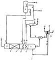
- FIG. 1 shows the beginning of the purification and disassembly chain of a cracked gas, obtained from a liquid hydrocarbon-containing feed, according to the prior art in an overview.
- the cracked gas 1 is fed into the lower section 21 of a mass transfer column 20, which uses two liquid hydrocarbon fractions 41 and 42, which contain predominantly heavy oils and heavy gasoline, as detergents.
- the mass transfer column 20 is divided into two sections, an upper section 22 and the mentioned lower section 21. The separation takes place by means of a chimney neck 24, which is impassable for the downflowing liquid and passable for the ascending gas phase.
- the mass transfer column 20 has various elements. In the lower section of the mass transfer column 21 are cascade bottoms 23. The upper section 22 also contains some cascade bottoms 23 and higher efficiency elements such as sieve plates 25.
- the cracked gas 1 is fed to the lower portion of the mass transfer column 20 and thereby comes into intensive contact with the descending detergents 41 and 42. By contact with the detergents 41 and 42 is the cracked gas cooled above all. Heavy oil components and solid coke particles are washed out of the cracked gas. The freed from the heavy oil components and coke particles cracked gas 2 leaves the mass transfer column 20 overhead. From the bottom of the mass transfer column 20, a liquid phase is withdrawn, which contains all solid coke particles and the heavy oil components of the cracking gas.
- the mass transfer column 20 is referred to in the art as Primary Oil Fractionater, oil wash column or oil scrubber.
- wash water column 90 This wash water column 90 is also referred to as water washing.
- elements 15 In the wash water column 90 above all simple elements such as cascade bottoms 13 are used in the lower part.
- elements 15 In the upper part there are elements 15 with higher efficiency such as trays, valve trays, mesh packings, structured packings and / or random packing fillings.
- the wash water column 90 is abandoned at the top of cold water 31 as a detergent.
- the rising cracked gas 2 is freed from further impurities such as gasoline components and further cooled.
- a liquid fraction 4 is withdrawn from the bottom of the wash water column 90, which contains mainly the gasoline components and water.
- the gaseous product 5, which leaves the wash water column 90 overhead, is now freed from heavy oil components, gasoline components and solid coke particles and can be separated below into the individual hydrocarbon fractions, in particular ethylene or propylene (not shown further).
- the present invention has for its object to simplify the purification of a cracking gas, as it arises in the thermal decomposition of liquid hydrocarbon-containing inserts. In particular, the expenditure on equipment should be reduced.
- the basic idea of the invention is to purify the fission gas formed during the thermal decomposition of the liquid hydrocarbonaceous feed successively only with a gasoline-rich fraction and a water-rich fraction as the detergent.
- a gasoline-rich fraction and a water-rich fraction as the detergent.
- the washing column used is similar to the washing water column known methods or systems constructed and procedurally divided into a lower portion and an upper portion.
- the lower section and the upper section may differ depending on the elements used.
- the cleavage gas is passed in succession through the lower portion and the upper portion of the scrubber in countercurrent to the liquid scrubbers, as mentioned, a gasoline-rich fraction and a water-rich fraction.
- the upper section of the wash column, the water-rich fraction is given up as a detergent.
- the lower portion of the wash column, the gasoline-rich fraction is given up as a detergent.
- the cracked gas is in the lower portion of the wash column on the local elements in intensive contact with the descending gasoline-rich fraction.
- the descending gasoline-rich fraction removes from the cracking gas heavy oil components and solid coke particles.
- the rising cracking gas is cooled.
- the rising cracking gas then passes into the upper section of the wash column. Gasoline components contained in the cracking gas (from the cracking and from the gasoline-rich fraction used as detergent in the lower section of the washing column) are washed out in the upper section with the water-rich fraction as detergent.
- a gasoline-water phase is obtained
- a "gasoline-rich fraction” is understood as meaning a fluid which has a high content of gasoline as defined below, ie at least 80%, in particular at least 90%, 95% or 99% gasoline. It can also be (essentially) pure gasoline.
- a "water-rich fraction” is a fraction which has a high water content, ie at least 80%, in particular at least 90%, 95% or 99% water.
- a “water-rich fraction” is in particular so-called process water, ie essentially pure water, which may still be supplied with appropriate auxiliaries.
- the "water-rich fraction” can also be separated from the aforementioned gasoline-water phase.
- the cracked gas is passed directly into the wash column as a first purification step.
- a “purification step” or a “purification” is understood to be a process step in which one or more predetermined components are removed from the cleavage gas.
- the term “gap gas” refers to the gas leaving the cracking furnace.
- “mild cleavage conditions” are understood as meaning such conditions in the cracking furnace in which the thermal cleavage of the hydrocarbon-containing insert is carried out with mild selectivity, ie. at low resolution, takes place.
- Cracking severity is an important parameter in the processes used here for the production of olefins by cleavage of hydrocarbon-containing deposits. It is determined by the cracking conditions used.
- the cracking conditions are particularly influenced by the temperature and the residence time and the partial pressures of the components of the hydrocarbon-containing feed and of the water vapor.
- the composition of the hydrocarbonaceous insert and the type of the cracking furnace (s) used also influence the cracking conditions. Due to the reciprocal influence of these factors on each other an indication of the specific individual parameters is often not meaningful.
- the cracking conditions are therefore also indicated by the ratio of propylene to ethylene in the cracking gas (so-called P / E ratio).
- mild cleavage conditions lead to a ratio of propylene to ethylene of at least 0.7 kg / kg, in particular from 0.7 to 1.6 kg / kg, preferably from 0.8 to 1.4 kg / kg, particularly preferably from 0 , 85 to 1.2 kg / kg at the outlet of the cracking furnace. It may also be advantageous to use fission conditions which result in a ratio of propylene to ethylene at the exit of the cracking furnace of 0.75 to 1.5 kg / kg or of 0.8 to 1.2 kg / kg or of 0.85 to 1, 15 kg / kg lead.
- a temperature of the quenching gas directly at the outlet of the cracking furnace between 720 ° C and 800 ° C and its pressure between 1 barg and 4 barg, preferably between 2.5 and 4 barg.
- the pressures in barg here refer to superatmospheric pressure, i. 1 barg means 1 bar above atmospheric pressure.
- Equally expedient is the addition of steam for hydrocarbonaceous use before the cracking furnace in a mass ratio of water vapor to hydrocarbons in the hydrocarbon-containing feed between 0.15 kg / kg and 0.45 kg / kg, preferably between 0.2 kg / kg and 0.35 kg / kg.
- the invention can take advantage of the fact that relatively large amounts of (pyrolysis) gasoline are formed in the thermal cracking of hydrocarbons of conventional composition, such as, for example, naphtha, under mild conditions of fission.
- This gasoline can be used directly as a detergent, ie as the "gasoline-rich fraction", so that the invention is not dependent on the provision of off-line detergents.
- the gasoline can also be formed in a start-up operation of the system, or whenever additional gasoline is needed.
- the inventive method therefore proves to be particularly cost effective and allows a meaningful use of the already incurred gasoline.
- Gasoline not used as a detergent may be discharged at the line boundary, fractionated and / or recycled to cleavage.
- the invention thus enables the generation always exactly the amount of gasoline required as a detergent. Losses, for example due to a not completely complete separation from the gasoline-water phase (see below) and / or by evaporation, can be compensated at any time from the process itself. It can also be provided to operate a corresponding system only with the mild cleavage conditions when gasoline is needed as a detergent, for example, at startup.
- gasoline which includes the mentioned pyrolysis gasoline
- a hydrocarbon fraction which boils to 80% at a temperature of 130 ° C at atmospheric pressure. At a temperature above 180 ° C, such a fraction is completely evaporated. Accordingly, a gasoline-water phase is understood as meaning a mixture of such a hydrocarbon fraction and water.
- the terms “gasoline”, “gasoline fraction” and “gasoline phase” are used synonymously in the context of this application. It is understood that the gasoline may also contain some impurities with other components, such as other hydrocarbons and water.
- the gasoline-rich fraction used as a detergent has at least the above-mentioned contents of gasoline or the boiling point of gasoline defining hydrocarbons.
- a "direct" feed of the cracking gas into the wash column is understood to mean a direct fluidic connection between cracking furnace and washing column, which does not contain intermediate laundry or similar cleaning steps.
- Certain structural measures such as a pipe guide with kink, where solid particles or the like can collect, are not understood in the context of the invention as an intermediate cleaning step.
- the scrubbing column is procedurally separated by a tray into the lower portion and the upper portion, wherein no liquid can pass the tray from top to bottom.
- the scrubbing column is thus designed as a two-pass column.
- the two procedurally separate parts are each charged with a separate detergent, namely the aforementioned gasoline and water-rich fractions, and have a separate liquid discharge from the bottom of the respective parts.
- a liquid phase containing the heavy oil components and coke particles is withdrawn from the bottom of the scrubbing column, ie the lower section.
- the cracked gas leaves the scrubbing column in gaseous form overhead and is cleaned of coke particles, heavy oils and a gasoline fraction.
- a liquid gasoline-water phase is withdrawn from the bottom separating the scrubbing column into the lower section and the upper section. This allows the separation of this phase later in a gasoline phase and a water phase, wherein both phases are recovered separately as detergent in the form of the gasoline or water-rich fraction.
- the liquid phase which is withdrawn from the bottom of the wash column, so its lower portion, in a first liquid phase containing the coke particles, and a second liquid phase containing a heavy oil fraction, separated.
- first liquid phase containing the coke particles
- second liquid phase containing a heavy oil fraction
- the liquid gasoline-water phase is, as mentioned, according to the invention separated into a liquid gasoline fraction and a liquid water fraction, the liquid gasoline fraction at least partially the lower part of the wash column as the gasoline-rich fraction and the liquid water fraction at least partially the upper part of the wash column the water-rich fraction is applied as a detergent. This allows recycling of the individual phases.
- a heavy oil fraction is understood as meaning a hydrocarbon fraction which boils at 80% at a temperature of 460 ° C. at atmospheric pressure. At a temperature above 560 ° C such a fraction is completely evaporated. Accordingly, an oil-water phase is understood as meaning a mixture of such a heavy oil fraction and water.
- the present invention eliminates an entire wash column, the so-called Primary Oil Fractionator, also for corresponding "heavier” uses such as naphtha.
- the purification of the cracked gas from heavy oil, gasoline components and solid coke particles is carried out in a scrubbing column in which a water-rich fraction is added as an overhead detergent in an upper section and further a gasoline-rich fraction which can be produced by the process itself. is abandoned in a lower section.
- the cracked gas 1 is fed directly from the cracking furnace the lower portion 11 of the wash column 10.
- the scrubbing column 10 is procedurally subdivided by a chimney neck bottom 14 into the lower section 11 and an upper section 12.
- the lower section 11 contains mainly simple elements such as cascade floors. Cascading floors in this embodiment are angular elements arranged in the lower part such that the apex of the angle points upwards.
- elements 15 higher efficiency In the upper part 12 of the scrubbing column 10 are elements 15 higher efficiency. These can be, for example, structured packings and / or random packings.
- the upper section 12 of the washing column 10, water or a water-rich fraction 31 is abandoned as a detergent.
- the lower section 11 of the scrubbing column 10 is a liquid gasoline rich fraction 43 is abandoned as a detergent.
- the cracked gas 1 is guided into the lower part 11 of the scrubbing column 10 and is in intensive contact with the descending detergent 43 via the elements 13.
- the liquid gasoline-rich fraction 43 flowing down removes heavy oils and solid coke particles from the cracked gas 1.
- the rising gap gas 1 is cooled.
- the rising cracked gas 1 passes through the chimney neck bottom 14 and enters the upper part 12 of the washing column 10.
- the chimney neck bottom 14 is designed such that it is impassable for the descending water-rich fraction 31 of the upper portion 12 of the washing column 10.
- the gas phase passing through the chimney neck 14 is already freed of all solid coke particles as well as of heavy oils, but still contains heavy gasoline impurities. These gasoline impurities are washed out in the upper part with the water-rich fraction 31 as a detergent. Accordingly, collects on the chimney neck 14, a mixed gasoline-water phase 51, which is subtracted from the chimney tray 14.
- the withdrawn gasoline-water phase 51 is fed to a gasoline-water separator 74.
- a water phase separates, which is supplied to the wash column 10 at the top as a water-rich fraction 31 again.
- the petrol phase separated in the gasoline-water separator 74 is fed to the lower part of the scrubbing column 10 as a gasoline-rich fraction 43.
- a further water phase 52 is obtained in the gasoline-water separator 74, which is integrated into the process water circuit of the system.
- a portion of the gasoline phase (the excess that is not needed for the gaswash cycle of water scrubbing) is separated as gasoline product 46 and run and / or split again for further processing (eg, gasoline hydrogenation or aromatics recovery).
- a liquid phase 4 is withdrawn, which contains all heavy oil components and coke particles.
- the withdrawn liquid phase 4 is first fed into a centrifugal separator (cyclone) 71.
- the centrifugal separator 71 the solid coke particles settle preferentially on the ground, and are conducted in a liquid fraction 63 into a filter system 72.
- a liquid fraction 62 is withdrawn, which contains only very fine solid coke particles. This is fed to a stripper 73, where a gaseous hydrocarbon fraction 45 (mainly hydrocarbons having 4 to 9 carbon atoms) is stripped out by supplying water vapor 32 and reintroduced to the wash column 10 in the lower section 11.
- a gaseous hydrocarbon fraction 45 mainly hydrocarbons having 4 to 9 carbon atoms
- a heavy oil phase 66 is withdrawn from the bottom of the stripper 73.
- the solid coke particles are separated from the liquid phase 65, which is guided back into the split gas stream 1.
- this is acted upon by steam 33.
- the stream 64 which contains all solid coke particles, free of volatile hydrocarbons and thus can be removed from the filter system 72 and disposed of.
- an exhaust gas 52 is formed.
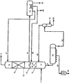
- FIG. 3 is similar to the embodiment according to FIG. 2 , Like parts and streams have been referred to here with like numbers.
- the wash column 10 consists of a lower portion 11 and an upper portion 12, wherein both sections are separated by a flue neck 14 procedurally.
- the upper portion 12 is, analogous to the embodiment according to FIG. 2 , Water 31 as a detergent in the head abandoned. From the bottom of the upper portion 12 is analogous to the embodiment of FIG. 2 drawn off a gasoline-water phase 51 and similar to the embodiment according to FIG. 2 separated into the individual components. This will not be shown here.
- a liquid phase 4 In contrast to the embodiment according to FIG. 2 is withdrawn from the bottom of the lower section 11, a liquid phase 4 and directly into a multiple Gravity separator 75 out.
- the multiple gravitational separator 75 has a plurality of depressions in which the solid coke particles collect. From these recesses, a liquid phase 63 is withdrawn, which contains all coke particles.
- the liquid phase 63 is fed into a filter system 72 and analogous to that in FIG. 2 described embodiment treated (not shown)
- a hydrocarbon fraction 62 is likewise obtained which contains only very fine coke particles and, analogously to the exemplary embodiment according to FIG. 2 treated.
- the treatment of the water fraction 31 and the gasoline-water phase 51 also corresponds to the descriptions of the embodiment according to FIG. 2 ,
- the same streams and apparatus have been given the same reference numerals in both embodiments
Applications Claiming Priority (2)
| Application Number | Priority Date | Filing Date | Title |
|---|---|---|---|
| DE102012006992A DE102012006992A1 (de) | 2012-04-05 | 2012-04-05 | Verfahren zur Trennung von Olefinen bei milder Spaltung |
| PCT/EP2013/000973 WO2013149721A1 (de) | 2012-04-05 | 2013-04-02 | Verfahren zur trennung von olefinen bei milder spaltung |
Publications (2)
| Publication Number | Publication Date |
|---|---|
| EP2834324A1 EP2834324A1 (de) | 2015-02-11 |
| EP2834324B1 true EP2834324B1 (de) | 2016-07-06 |
Family
ID=48128255
Family Applications (1)
| Application Number | Title | Priority Date | Filing Date |
|---|---|---|---|
| EP13716729.2A Active EP2834324B1 (de) | 2012-04-05 | 2013-04-02 | Verfahren zur trennung von olefinen bei milder spaltung |
Country Status (12)
| Country | Link |
|---|---|
| US (1) | US9969662B2 (ru) |
| EP (1) | EP2834324B1 (ru) |
| JP (1) | JP6104360B2 (ru) |
| KR (1) | KR102033158B1 (ru) |
| CN (1) | CN104350132B (ru) |
| AU (1) | AU2013243037B2 (ru) |
| DE (1) | DE102012006992A1 (ru) |
| ES (1) | ES2593327T3 (ru) |
| HU (1) | HUE028975T2 (ru) |
| PH (1) | PH12014502254B1 (ru) |
| RU (1) | RU2624010C2 (ru) |
| WO (1) | WO2013149721A1 (ru) |
Families Citing this family (6)
| Publication number | Priority date | Publication date | Assignee | Title |
|---|---|---|---|---|
| US10005004B2 (en) | 2013-09-25 | 2018-06-26 | Linde Aktiengesellschaft | Oil scrubbing column |
| AU2014327819B2 (en) * | 2013-09-25 | 2018-07-26 | Linde Aktiengesellschaft | Method for cleaning a cracking gas stream in a primary fractionation column |
| CN103759772B (zh) * | 2014-01-27 | 2017-12-05 | 兰州海默科技股份有限公司 | 一种全量程计量稠油中油气水三相流量的装置和方法 |
| DE102016004434A1 (de) * | 2016-04-12 | 2017-10-12 | Linde Aktiengesellschaft | Dekanter-Böden im Kolonnensumpf zur Abtrennung von Kohlenwasserstoffen aus wässrigen Lösungen und umgekehrt |
| EP3424582A1 (de) * | 2017-07-06 | 2019-01-09 | Linde Aktiengesellschaft | Verfahren und anlage zur trenntechnischen bearbeitung eines ausgangsgemischs |
| CN109569191A (zh) * | 2019-01-25 | 2019-04-05 | 彭圆 | 一种多级焦化废气处理装置 |
Family Cites Families (29)
| Publication number | Priority date | Publication date | Assignee | Title |
|---|---|---|---|---|
| US2014724A (en) * | 1934-03-20 | 1935-09-17 | Texas Co | Manufacture of olefines |
| US2464810A (en) * | 1944-08-25 | 1949-03-22 | Foster Wheeler Corp | Catalytic conversion |
| GB851437A (en) * | 1958-06-09 | 1960-10-19 | Exxon Research Engineering Co | Process of steam-cracked naphtha light end products |
| US3060116A (en) * | 1959-11-06 | 1962-10-23 | Socony Mobil Oil Co Inc | Combination reforming and cracking process |
| GB1310438A (en) * | 1970-03-20 | 1973-03-21 | Stone Webster Eng Corp | Removal of acidic gases from hydrocarbon streams |
| US3691058A (en) * | 1970-04-15 | 1972-09-12 | Exxon Research Engineering Co | Production of single-ring aromatic hydrocarbons from gas oils containing condensed ring aromatics and integrating this with the visbreaking of residua |
| US3923921A (en) * | 1971-03-01 | 1975-12-02 | Exxon Research Engineering Co | Naphtha steam-cracking quench process |
| US4060399A (en) * | 1976-08-30 | 1977-11-29 | Gleason Thomas G | Scrubber-cooler tower |
| US4548706A (en) * | 1983-01-26 | 1985-10-22 | Standard Oil Company (Indiana) | Thermal cracking of hydrocarbons |
| JPS61176692A (ja) * | 1985-01-31 | 1986-08-08 | Mitsui Eng & Shipbuild Co Ltd | 炭化水素熱分解ガスの冷却方法 |
| US4831205A (en) * | 1987-12-16 | 1989-05-16 | Mobil Oil Corporation | Catalytic conversion of light olefinic feedstocks in a FCC plant |
| GB8904408D0 (en) * | 1989-02-27 | 1989-04-12 | Shell Int Research | Process for the conversion of a hydrocarbonaceous feedstock |
| AU3151793A (en) * | 1991-12-11 | 1993-07-19 | Exxon Chemical Patents Inc. | Method for simplifying quench and tar removal facilities in steam crackers |
| US5464536A (en) * | 1992-06-10 | 1995-11-07 | Charles W. Taggart | Apparatus for centrifugally separating a fluid mixture into its component parts |
| US5877380A (en) * | 1997-10-27 | 1999-03-02 | The M. W. Kellogg Company | Quench oil viscosity control in pyrolysis fractionator |
| US6013852A (en) * | 1997-11-21 | 2000-01-11 | Shell Oil Company | Producing light olefins from a contaminated liquid hydrocarbon stream by means of thermal cracking |
| US6235961B1 (en) | 1999-01-29 | 2001-05-22 | Stone & Webster Engineering Corporation | Process for pretreating cracked gas before caustic tower treatment in ehtylene plants |
| US20010042700A1 (en) * | 2000-04-17 | 2001-11-22 | Swan, George A. | Naphtha and cycle oil conversion process |
| DE10026135A1 (de) * | 2000-05-26 | 2001-11-29 | Basf Ag | Verfahren und Vorrichtung zur Entfernung von Kohlenwasserstoffen aus der Ablauge von Laugewäschern |
| US7011740B2 (en) | 2002-10-10 | 2006-03-14 | Kellogg Brown & Root, Inc. | Catalyst recovery from light olefin FCC effluent |
| US7128827B2 (en) * | 2004-01-14 | 2006-10-31 | Kellogg Brown & Root Llc | Integrated catalytic cracking and steam pyrolysis process for olefins |
| BRPI0513338B1 (pt) * | 2004-07-16 | 2015-11-03 | Asahi Kasei Chemicals Corp | métodos de produção de etileno e propileno |
| PL1962992T3 (pl) * | 2005-12-19 | 2012-09-28 | Fluor Tech Corp | Dwustopniowy skruber szybko chłodzący |
| EP1999235B1 (en) * | 2006-03-29 | 2018-09-05 | Shell International Research Maatschappij B.V. | Process for producing lower olefins |
| JP5476558B2 (ja) * | 2006-08-02 | 2014-04-23 | 公益財団法人ヒューマンサイエンス振興財団 | 水試料中の原虫のろ過回収方法および水道水又は水道原水の水質の管理方法 |
| DE102006045498A1 (de) * | 2006-09-27 | 2008-04-10 | Linde Ag | Verfahren zur Wasserwäsche in einer Olefinanlage |
| US7628197B2 (en) * | 2006-12-16 | 2009-12-08 | Kellogg Brown & Root Llc | Water quench fitting for pyrolysis furnace effluent |
| AU2009216164B2 (en) * | 2008-02-22 | 2011-10-13 | Mitsubishi Heavy Industries, Ltd. | Apparatus for recovering CO2 and method of recovering CO2 |
| DE102010022501A1 (de) * | 2010-06-02 | 2011-12-08 | Linde Aktiengesellschaft | Verfahren und Vorrichtung zur Wäsche von Synthesegas |
-
2012
- 2012-04-05 DE DE102012006992A patent/DE102012006992A1/de not_active Withdrawn
-
2013
- 2013-04-02 AU AU2013243037A patent/AU2013243037B2/en not_active Ceased
- 2013-04-02 ES ES13716729.2T patent/ES2593327T3/es active Active
- 2013-04-02 CN CN201380018714.9A patent/CN104350132B/zh active Active
- 2013-04-02 WO PCT/EP2013/000973 patent/WO2013149721A1/de active Application Filing
- 2013-04-02 RU RU2014144292A patent/RU2624010C2/ru active
- 2013-04-02 KR KR1020147031059A patent/KR102033158B1/ko active IP Right Grant
- 2013-04-02 HU HUE13716729A patent/HUE028975T2/en unknown
- 2013-04-02 US US14/390,922 patent/US9969662B2/en active Active
- 2013-04-02 EP EP13716729.2A patent/EP2834324B1/de active Active
- 2013-04-02 JP JP2015503781A patent/JP6104360B2/ja not_active Expired - Fee Related
-
2014
- 2014-10-07 PH PH12014502254A patent/PH12014502254B1/en unknown
Also Published As
| Publication number | Publication date |
|---|---|
| JP6104360B2 (ja) | 2017-03-29 |
| CN104350132B (zh) | 2016-10-26 |
| US9969662B2 (en) | 2018-05-15 |
| ES2593327T3 (es) | 2016-12-07 |
| KR102033158B1 (ko) | 2019-10-16 |
| EP2834324A1 (de) | 2015-02-11 |
| AU2013243037A1 (en) | 2014-10-09 |
| PH12014502254A1 (en) | 2014-12-15 |
| JP2015514099A (ja) | 2015-05-18 |
| KR20140143448A (ko) | 2014-12-16 |
| RU2014144292A (ru) | 2016-05-27 |
| DE102012006992A1 (de) | 2013-10-10 |
| HUE028975T2 (en) | 2017-01-30 |
| AU2013243037B2 (en) | 2017-03-30 |
| US20150065770A1 (en) | 2015-03-05 |
| CN104350132A (zh) | 2015-02-11 |
| RU2624010C2 (ru) | 2017-06-30 |
| PH12014502254B1 (en) | 2014-12-15 |
| WO2013149721A1 (de) | 2013-10-10 |
Similar Documents
| Publication | Publication Date | Title |
|---|---|---|
| EP2834324B1 (de) | Verfahren zur trennung von olefinen bei milder spaltung | |
| DE10217863A1 (de) | Verfahren und Vorrichtung zur Olefinherstellung | |
| EP2867339A1 (de) | Verfahren zum herstellen von olefinen durch thermisches dampfspalten | |
| EP2557071B1 (de) | Trennsequenz für Kohlenwasserstoffe aus milder thermischer Spaltung | |
| EP1357165A1 (de) | Verfahren und Vorrichtung zur Olefinherstellung | |
| WO2015071105A1 (de) | Verfahren zur auftrennung eines kohlenwasserstoffgemischs, trennanlage und dampfspaltanlage | |
| EP3652138A1 (de) | Prozess und anlage zur herstellung von propylen durch kombination von propandehydrierung und dampfspaltverfahren mit vortrennschritten in beiden verfahren zur teilweise entfernung von wasserstoff und methan | |
| WO2010086092A1 (de) | Verfahren und vorrichtung zur abtrennung von festen partikeln aus einer wasserphase | |
| EP3714023B1 (de) | Verfahren und anlage zur gewinnung polymerisierbarer aromatischer verbindungen | |
| DE102008051058B4 (de) | Verfahren zur Abtrennung von festen Partikeln aus einer Wasserphase in einer Anlage zur Erzeugung von Kohlenwasserstoffen | |
| BE1029922B1 (de) | Verfahren und Vorrichtung zur Trennung eines kohlenwasserstoffhaltigen Einsatzstoffstroms durch Extraktivdestillation | |
| BE1029921B1 (de) | Verfahren und Vorrichtung zur Trennung eines kohlenwasserstoffhaltigen Einsatzstoffstroms durch Extraktivdestillation | |
| EP3137577B1 (de) | Verfahren zur gewinnung von rohölprodukten | |
| DE852885C (de) | Verfahren zur katalytischen Spaltung von Kohlenwasserstoffoelen | |
| DE102019135889A1 (de) | Verfahren und eine Anlage zur Gewinnung von Kohlenwasserstoffen | |
| EP3137578A1 (de) | Verfahren und anlage zur gewinnung von rohölprodukten | |
| DE102014006326A1 (de) | Verfahren und Anlage zur Gewinnung von Rohölprodukten | |
| DE102014006327A1 (de) | Verfahren und Anlage zur Gewinnung von Rohölprodukten | |
| DE1543139A1 (de) | Verfahren zur Pyrolyse von Kohlenwasserstoffen | |
| EP3350287A1 (de) | Verfahren und anlage zur trenntechnischen bearbeitung eines kohlenwasserstoffe und schwefelverbindungen enthaltenden stoffgemischs | |
| DD210398A3 (de) | Verfahren zur gewinnung von c tief 1/c tief 2-komponenten und c tief 3,- i-c tief 4 und n-c tief 4- fraktionen hoher reinheit |
Legal Events
| Date | Code | Title | Description |
|---|---|---|---|
| PUAI | Public reference made under article 153(3) epc to a published international application that has entered the european phase |
Free format text: ORIGINAL CODE: 0009012 |
|
| 17P | Request for examination filed |
Effective date: 20140916 |
|
| AK | Designated contracting states |
Kind code of ref document: A1 Designated state(s): AL AT BE BG CH CY CZ DE DK EE ES FI FR GB GR HR HU IE IS IT LI LT LU LV MC MK MT NL NO PL PT RO RS SE SI SK SM TR |
|
| AX | Request for extension of the european patent |
Extension state: BA ME |
|
| DAX | Request for extension of the european patent (deleted) | ||
| REG | Reference to a national code |
Ref country code: DE Ref legal event code: R079 Ref document number: 502013003614 Country of ref document: DE Free format text: PREVIOUS MAIN CLASS: C10G0009000000 Ipc: C07C0007110000 |
|
| GRAP | Despatch of communication of intention to grant a patent |
Free format text: ORIGINAL CODE: EPIDOSNIGR1 |
|
| RIC1 | Information provided on ipc code assigned before grant |
Ipc: B01D 53/18 20060101ALI20151022BHEP Ipc: C10G 9/00 20060101ALI20151022BHEP Ipc: C10G 9/36 20060101ALI20151022BHEP Ipc: B01J 19/24 20060101ALI20151022BHEP Ipc: C07C 7/11 20060101AFI20151022BHEP Ipc: B01D 53/14 20060101ALI20151022BHEP Ipc: C07C 4/04 20060101ALI20151022BHEP |
|
| INTG | Intention to grant announced |
Effective date: 20151119 |
|
| GRAS | Grant fee paid |
Free format text: ORIGINAL CODE: EPIDOSNIGR3 |
|
| INTG | Intention to grant announced |
Effective date: 20160212 |
|
| GRAA | (expected) grant |
Free format text: ORIGINAL CODE: 0009210 |
|
| AK | Designated contracting states |
Kind code of ref document: B1 Designated state(s): AL AT BE BG CH CY CZ DE DK EE ES FI FR GB GR HR HU IE IS IT LI LT LU LV MC MK MT NL NO PL PT RO RS SE SI SK SM TR |
|
| REG | Reference to a national code |
Ref country code: GB Ref legal event code: FG4D Free format text: NOT ENGLISH |
|
| REG | Reference to a national code |
Ref country code: AT Ref legal event code: REF Ref document number: 810590 Country of ref document: AT Kind code of ref document: T Effective date: 20160715 Ref country code: CH Ref legal event code: EP |
|
| REG | Reference to a national code |
Ref country code: IE Ref legal event code: FG4D Free format text: LANGUAGE OF EP DOCUMENT: GERMAN |
|
| REG | Reference to a national code |
Ref country code: DE Ref legal event code: R096 Ref document number: 502013003614 Country of ref document: DE |
|
| REG | Reference to a national code |
Ref country code: NL Ref legal event code: FP |
|
| REG | Reference to a national code |
Ref country code: LT Ref legal event code: MG4D |
|
| REG | Reference to a national code |
Ref country code: ES Ref legal event code: FG2A Ref document number: 2593327 Country of ref document: ES Kind code of ref document: T3 Effective date: 20161207 |
|
| REG | Reference to a national code |
Ref country code: HU Ref legal event code: AG4A Ref document number: E028975 Country of ref document: HU |
|
| PG25 | Lapsed in a contracting state [announced via postgrant information from national office to epo] |
Ref country code: NO Free format text: LAPSE BECAUSE OF FAILURE TO SUBMIT A TRANSLATION OF THE DESCRIPTION OR TO PAY THE FEE WITHIN THE PRESCRIBED TIME-LIMIT Effective date: 20161006 Ref country code: IS Free format text: LAPSE BECAUSE OF FAILURE TO SUBMIT A TRANSLATION OF THE DESCRIPTION OR TO PAY THE FEE WITHIN THE PRESCRIBED TIME-LIMIT Effective date: 20161106 Ref country code: HR Free format text: LAPSE BECAUSE OF FAILURE TO SUBMIT A TRANSLATION OF THE DESCRIPTION OR TO PAY THE FEE WITHIN THE PRESCRIBED TIME-LIMIT Effective date: 20160706 Ref country code: FI Free format text: LAPSE BECAUSE OF FAILURE TO SUBMIT A TRANSLATION OF THE DESCRIPTION OR TO PAY THE FEE WITHIN THE PRESCRIBED TIME-LIMIT Effective date: 20160706 Ref country code: LT Free format text: LAPSE BECAUSE OF FAILURE TO SUBMIT A TRANSLATION OF THE DESCRIPTION OR TO PAY THE FEE WITHIN THE PRESCRIBED TIME-LIMIT Effective date: 20160706 Ref country code: RS Free format text: LAPSE BECAUSE OF FAILURE TO SUBMIT A TRANSLATION OF THE DESCRIPTION OR TO PAY THE FEE WITHIN THE PRESCRIBED TIME-LIMIT Effective date: 20160706 Ref country code: IT Free format text: LAPSE BECAUSE OF FAILURE TO SUBMIT A TRANSLATION OF THE DESCRIPTION OR TO PAY THE FEE WITHIN THE PRESCRIBED TIME-LIMIT Effective date: 20160706 |
|
| PG25 | Lapsed in a contracting state [announced via postgrant information from national office to epo] |
Ref country code: GR Free format text: LAPSE BECAUSE OF FAILURE TO SUBMIT A TRANSLATION OF THE DESCRIPTION OR TO PAY THE FEE WITHIN THE PRESCRIBED TIME-LIMIT Effective date: 20161007 Ref country code: SE Free format text: LAPSE BECAUSE OF FAILURE TO SUBMIT A TRANSLATION OF THE DESCRIPTION OR TO PAY THE FEE WITHIN THE PRESCRIBED TIME-LIMIT Effective date: 20160706 Ref country code: PT Free format text: LAPSE BECAUSE OF FAILURE TO SUBMIT A TRANSLATION OF THE DESCRIPTION OR TO PAY THE FEE WITHIN THE PRESCRIBED TIME-LIMIT Effective date: 20161107 Ref country code: LV Free format text: LAPSE BECAUSE OF FAILURE TO SUBMIT A TRANSLATION OF THE DESCRIPTION OR TO PAY THE FEE WITHIN THE PRESCRIBED TIME-LIMIT Effective date: 20160706 Ref country code: PL Free format text: LAPSE BECAUSE OF FAILURE TO SUBMIT A TRANSLATION OF THE DESCRIPTION OR TO PAY THE FEE WITHIN THE PRESCRIBED TIME-LIMIT Effective date: 20160706 |
|
| REG | Reference to a national code |
Ref country code: FR Ref legal event code: PLFP Year of fee payment: 5 |
|
| REG | Reference to a national code |
Ref country code: DE Ref legal event code: R097 Ref document number: 502013003614 Country of ref document: DE |
|
| PG25 | Lapsed in a contracting state [announced via postgrant information from national office to epo] |
Ref country code: EE Free format text: LAPSE BECAUSE OF FAILURE TO SUBMIT A TRANSLATION OF THE DESCRIPTION OR TO PAY THE FEE WITHIN THE PRESCRIBED TIME-LIMIT Effective date: 20160706 Ref country code: RO Free format text: LAPSE BECAUSE OF FAILURE TO SUBMIT A TRANSLATION OF THE DESCRIPTION OR TO PAY THE FEE WITHIN THE PRESCRIBED TIME-LIMIT Effective date: 20160706 |
|
| PLBE | No opposition filed within time limit |
Free format text: ORIGINAL CODE: 0009261 |
|
| STAA | Information on the status of an ep patent application or granted ep patent |
Free format text: STATUS: NO OPPOSITION FILED WITHIN TIME LIMIT |
|
| PG25 | Lapsed in a contracting state [announced via postgrant information from national office to epo] |
Ref country code: SM Free format text: LAPSE BECAUSE OF FAILURE TO SUBMIT A TRANSLATION OF THE DESCRIPTION OR TO PAY THE FEE WITHIN THE PRESCRIBED TIME-LIMIT Effective date: 20160706 Ref country code: DK Free format text: LAPSE BECAUSE OF FAILURE TO SUBMIT A TRANSLATION OF THE DESCRIPTION OR TO PAY THE FEE WITHIN THE PRESCRIBED TIME-LIMIT Effective date: 20160706 Ref country code: BG Free format text: LAPSE BECAUSE OF FAILURE TO SUBMIT A TRANSLATION OF THE DESCRIPTION OR TO PAY THE FEE WITHIN THE PRESCRIBED TIME-LIMIT Effective date: 20161006 Ref country code: SK Free format text: LAPSE BECAUSE OF FAILURE TO SUBMIT A TRANSLATION OF THE DESCRIPTION OR TO PAY THE FEE WITHIN THE PRESCRIBED TIME-LIMIT Effective date: 20160706 |
|
| 26N | No opposition filed |
Effective date: 20170407 |
|
| PG25 | Lapsed in a contracting state [announced via postgrant information from national office to epo] |
Ref country code: SI Free format text: LAPSE BECAUSE OF FAILURE TO SUBMIT A TRANSLATION OF THE DESCRIPTION OR TO PAY THE FEE WITHIN THE PRESCRIBED TIME-LIMIT Effective date: 20160706 |
|
| REG | Reference to a national code |
Ref country code: CH Ref legal event code: PL |
|
| REG | Reference to a national code |
Ref country code: IE Ref legal event code: MM4A |
|
| PG25 | Lapsed in a contracting state [announced via postgrant information from national office to epo] |
Ref country code: MC Free format text: LAPSE BECAUSE OF FAILURE TO SUBMIT A TRANSLATION OF THE DESCRIPTION OR TO PAY THE FEE WITHIN THE PRESCRIBED TIME-LIMIT Effective date: 20160706 |
|
| PG25 | Lapsed in a contracting state [announced via postgrant information from national office to epo] |
Ref country code: LU Free format text: LAPSE BECAUSE OF NON-PAYMENT OF DUE FEES Effective date: 20170402 Ref country code: CH Free format text: LAPSE BECAUSE OF NON-PAYMENT OF DUE FEES Effective date: 20170430 Ref country code: LI Free format text: LAPSE BECAUSE OF NON-PAYMENT OF DUE FEES Effective date: 20170430 |
|
| REG | Reference to a national code |
Ref country code: FR Ref legal event code: PLFP Year of fee payment: 6 |
|
| PG25 | Lapsed in a contracting state [announced via postgrant information from national office to epo] |
Ref country code: IE Free format text: LAPSE BECAUSE OF NON-PAYMENT OF DUE FEES Effective date: 20170402 |
|
| PG25 | Lapsed in a contracting state [announced via postgrant information from national office to epo] |
Ref country code: MT Free format text: LAPSE BECAUSE OF FAILURE TO SUBMIT A TRANSLATION OF THE DESCRIPTION OR TO PAY THE FEE WITHIN THE PRESCRIBED TIME-LIMIT Effective date: 20160706 |
|
| PG25 | Lapsed in a contracting state [announced via postgrant information from national office to epo] |
Ref country code: AL Free format text: LAPSE BECAUSE OF FAILURE TO SUBMIT A TRANSLATION OF THE DESCRIPTION OR TO PAY THE FEE WITHIN THE PRESCRIBED TIME-LIMIT Effective date: 20160706 |
|
| PG25 | Lapsed in a contracting state [announced via postgrant information from national office to epo] |
Ref country code: CY Free format text: LAPSE BECAUSE OF FAILURE TO SUBMIT A TRANSLATION OF THE DESCRIPTION OR TO PAY THE FEE WITHIN THE PRESCRIBED TIME-LIMIT Effective date: 20160706 |
|
| PG25 | Lapsed in a contracting state [announced via postgrant information from national office to epo] |
Ref country code: MK Free format text: LAPSE BECAUSE OF FAILURE TO SUBMIT A TRANSLATION OF THE DESCRIPTION OR TO PAY THE FEE WITHIN THE PRESCRIBED TIME-LIMIT Effective date: 20160706 |
|
| PG25 | Lapsed in a contracting state [announced via postgrant information from national office to epo] |
Ref country code: TR Free format text: LAPSE BECAUSE OF FAILURE TO SUBMIT A TRANSLATION OF THE DESCRIPTION OR TO PAY THE FEE WITHIN THE PRESCRIBED TIME-LIMIT Effective date: 20160706 |
|
| REG | Reference to a national code |
Ref country code: DE Ref legal event code: R081 Ref document number: 502013003614 Country of ref document: DE Owner name: LINDE GMBH, DE Free format text: FORMER OWNER: LINDE AKTIENGESELLSCHAFT, 80331 MUENCHEN, DE |
|
| PGFP | Annual fee paid to national office [announced via postgrant information from national office to epo] |
Ref country code: CZ Payment date: 20230320 Year of fee payment: 11 |
|
| PGFP | Annual fee paid to national office [announced via postgrant information from national office to epo] |
Ref country code: NL Payment date: 20230417 Year of fee payment: 11 |
|
| PGFP | Annual fee paid to national office [announced via postgrant information from national office to epo] |
Ref country code: FR Payment date: 20230417 Year of fee payment: 11 Ref country code: ES Payment date: 20230517 Year of fee payment: 11 Ref country code: DE Payment date: 20230418 Year of fee payment: 11 |
|
| PGFP | Annual fee paid to national office [announced via postgrant information from national office to epo] |
Ref country code: HU Payment date: 20230329 Year of fee payment: 11 Ref country code: AT Payment date: 20230414 Year of fee payment: 11 |
|
| PGFP | Annual fee paid to national office [announced via postgrant information from national office to epo] |
Ref country code: BE Payment date: 20230417 Year of fee payment: 11 |
|
| PGFP | Annual fee paid to national office [announced via postgrant information from national office to epo] |
Ref country code: GB Payment date: 20230420 Year of fee payment: 11 |