US7011740B2 - Catalyst recovery from light olefin FCC effluent - Google Patents
Catalyst recovery from light olefin FCC effluent Download PDFInfo
- Publication number
- US7011740B2 US7011740B2 US10/065,377 US6537702A US7011740B2 US 7011740 B2 US7011740 B2 US 7011740B2 US 6537702 A US6537702 A US 6537702A US 7011740 B2 US7011740 B2 US 7011740B2
- Authority
- US
- United States
- Prior art keywords
- fines
- oil
- quench
- catalyst
- effluent gas
- Prior art date
- Legal status (The legal status is an assumption and is not a legal conclusion. Google has not performed a legal analysis and makes no representation as to the accuracy of the status listed.)
- Expired - Lifetime, expires
Links
- 239000003054 catalyst Substances 0.000 title claims abstract description 120
- 150000001336 alkenes Chemical class 0.000 title description 15
- JRZJOMJEPLMPRA-UHFFFAOYSA-N olefin Natural products CCCCCCCC=C JRZJOMJEPLMPRA-UHFFFAOYSA-N 0.000 title description 11
- 238000011084 recovery Methods 0.000 title description 5
- 238000010791 quenching Methods 0.000 claims abstract description 93
- 239000003921 oil Substances 0.000 claims abstract description 86
- 239000002002 slurry Substances 0.000 claims abstract description 47
- 238000000034 method Methods 0.000 claims abstract description 43
- 239000000295 fuel oil Substances 0.000 claims abstract description 37
- 238000001914 filtration Methods 0.000 claims description 21
- 238000011001 backwashing Methods 0.000 claims description 20
- 239000007788 liquid Substances 0.000 claims description 18
- 238000002485 combustion reaction Methods 0.000 claims description 17
- 238000002156 mixing Methods 0.000 claims description 14
- 238000000926 separation method Methods 0.000 claims description 13
- 239000000706 filtrate Substances 0.000 claims description 9
- 230000003134 recirculating effect Effects 0.000 claims description 7
- 238000001816 cooling Methods 0.000 claims description 6
- 238000005406 washing Methods 0.000 claims description 3
- 238000007599 discharging Methods 0.000 claims description 2
- 239000007789 gas Substances 0.000 abstract description 65
- 239000010724 circulating oil Substances 0.000 abstract description 5
- 238000004231 fluid catalytic cracking Methods 0.000 description 49
- JTJMJGYZQZDUJJ-UHFFFAOYSA-N phencyclidine Chemical class C1CCCCN1C1(C=2C=CC=CC=2)CCCCC1 JTJMJGYZQZDUJJ-UHFFFAOYSA-N 0.000 description 19
- 238000005243 fluidization Methods 0.000 description 15
- 239000000446 fuel Substances 0.000 description 15
- 238000006243 chemical reaction Methods 0.000 description 13
- 229930195733 hydrocarbon Natural products 0.000 description 11
- 150000002430 hydrocarbons Chemical class 0.000 description 11
- 230000008929 regeneration Effects 0.000 description 11
- 238000011069 regeneration method Methods 0.000 description 11
- 238000009826 distribution Methods 0.000 description 10
- 239000000571 coke Substances 0.000 description 7
- 230000001172 regenerating effect Effects 0.000 description 6
- 239000004215 Carbon black (E152) Substances 0.000 description 5
- 239000002737 fuel gas Substances 0.000 description 5
- 239000000203 mixture Substances 0.000 description 5
- 239000002245 particle Substances 0.000 description 5
- 239000000047 product Substances 0.000 description 5
- QVGXLLKOCUKJST-UHFFFAOYSA-N atomic oxygen Chemical compound [O] QVGXLLKOCUKJST-UHFFFAOYSA-N 0.000 description 4
- 229910052799 carbon Inorganic materials 0.000 description 4
- 238000010438 heat treatment Methods 0.000 description 4
- 229910052760 oxygen Inorganic materials 0.000 description 4
- 239000001301 oxygen Substances 0.000 description 4
- 238000012545 processing Methods 0.000 description 4
- OKTJSMMVPCPJKN-UHFFFAOYSA-N Carbon Chemical compound [C] OKTJSMMVPCPJKN-UHFFFAOYSA-N 0.000 description 3
- VGGSQFUCUMXWEO-UHFFFAOYSA-N Ethene Chemical compound C=C VGGSQFUCUMXWEO-UHFFFAOYSA-N 0.000 description 3
- 239000005977 Ethylene Substances 0.000 description 3
- 239000003546 flue gas Substances 0.000 description 3
- 239000011261 inert gas Substances 0.000 description 3
- 238000012856 packing Methods 0.000 description 3
- QQONPFPTGQHPMA-UHFFFAOYSA-N propylene Natural products CC=C QQONPFPTGQHPMA-UHFFFAOYSA-N 0.000 description 3
- 125000004805 propylene group Chemical group [H]C([H])([H])C([H])([*:1])C([H])([H])[*:2] 0.000 description 3
- UGFAIRIUMAVXCW-UHFFFAOYSA-N Carbon monoxide Chemical compound [O+]#[C-] UGFAIRIUMAVXCW-UHFFFAOYSA-N 0.000 description 2
- 230000015572 biosynthetic process Effects 0.000 description 2
- 238000004891 communication Methods 0.000 description 2
- 238000010790 dilution Methods 0.000 description 2
- 239000012895 dilution Substances 0.000 description 2
- 239000006185 dispersion Substances 0.000 description 2
- 238000005367 electrostatic precipitation Methods 0.000 description 2
- 239000012530 fluid Substances 0.000 description 2
- -1 for example Substances 0.000 description 2
- 238000004519 manufacturing process Methods 0.000 description 2
- 238000012986 modification Methods 0.000 description 2
- 230000004048 modification Effects 0.000 description 2
- BASFCYQUMIYNBI-UHFFFAOYSA-N platinum Chemical compound [Pt] BASFCYQUMIYNBI-UHFFFAOYSA-N 0.000 description 2
- 230000000153 supplemental effect Effects 0.000 description 2
- 238000005273 aeration Methods 0.000 description 1
- 239000003570 air Substances 0.000 description 1
- 238000000889 atomisation Methods 0.000 description 1
- 238000009835 boiling Methods 0.000 description 1
- 239000011449 brick Substances 0.000 description 1
- 238000004523 catalytic cracking Methods 0.000 description 1
- 238000006555 catalytic reaction Methods 0.000 description 1
- 239000012141 concentrate Substances 0.000 description 1
- 239000000470 constituent Substances 0.000 description 1
- 238000005336 cracking Methods 0.000 description 1
- 230000008021 deposition Effects 0.000 description 1
- 238000013461 design Methods 0.000 description 1
- 238000010586 diagram Methods 0.000 description 1
- 238000004821 distillation Methods 0.000 description 1
- 230000000694 effects Effects 0.000 description 1
- 230000005684 electric field Effects 0.000 description 1
- 230000003628 erosive effect Effects 0.000 description 1
- 238000011010 flushing procedure Methods 0.000 description 1
- 238000004508 fractional distillation Methods 0.000 description 1
- 239000003502 gasoline Substances 0.000 description 1
- 230000020169 heat generation Effects 0.000 description 1
- 230000001939 inductive effect Effects 0.000 description 1
- 238000009434 installation Methods 0.000 description 1
- 238000011068 loading method Methods 0.000 description 1
- 239000000463 material Substances 0.000 description 1
- 230000000116 mitigating effect Effects 0.000 description 1
- 239000012188 paraffin wax Substances 0.000 description 1
- 229910052697 platinum Inorganic materials 0.000 description 1
- 239000002574 poison Substances 0.000 description 1
- 231100000614 poison Toxicity 0.000 description 1
- 238000011027 product recovery Methods 0.000 description 1
- 238000000197 pyrolysis Methods 0.000 description 1
- 239000010454 slate Substances 0.000 description 1
- 239000007787 solid Substances 0.000 description 1
- 238000003860 storage Methods 0.000 description 1
- 239000013589 supplement Substances 0.000 description 1
- 238000004227 thermal cracking Methods 0.000 description 1
- 238000012546 transfer Methods 0.000 description 1
- 238000011144 upstream manufacturing Methods 0.000 description 1
- 238000009834 vaporization Methods 0.000 description 1
- 230000008016 vaporization Effects 0.000 description 1
- 239000002918 waste heat Substances 0.000 description 1
Images


Classifications
-
- C—CHEMISTRY; METALLURGY
- C10—PETROLEUM, GAS OR COKE INDUSTRIES; TECHNICAL GASES CONTAINING CARBON MONOXIDE; FUELS; LUBRICANTS; PEAT
- C10G—CRACKING HYDROCARBON OILS; PRODUCTION OF LIQUID HYDROCARBON MIXTURES, e.g. BY DESTRUCTIVE HYDROGENATION, OLIGOMERISATION, POLYMERISATION; RECOVERY OF HYDROCARBON OILS FROM OIL-SHALE, OIL-SAND, OR GASES; REFINING MIXTURES MAINLY CONSISTING OF HYDROCARBONS; REFORMING OF NAPHTHA; MINERAL WAXES
- C10G11/00—Catalytic cracking, in the absence of hydrogen, of hydrocarbon oils
- C10G11/14—Catalytic cracking, in the absence of hydrogen, of hydrocarbon oils with preheated moving solid catalysts
- C10G11/18—Catalytic cracking, in the absence of hydrogen, of hydrocarbon oils with preheated moving solid catalysts according to the "fluidised-bed" technique
- C10G11/182—Regeneration
Definitions
- the present invention relates to catalyst recovery from a light FCC-type effluent, and also to regeneration of the recovered catalyst.
- the reactor effluent is processed in a series of cyclone separators, usually housed in a vessel, that separate most of the catalyst from the effluent to be regenerated for recycle to a regenerator and then to the reactor, in a manner similar to conventional refinery FCC operations.
- the catalyst-lean hot effluent gases from the cyclones are then cooled and separated by fractional distillation, for example, into the product constituents.
- Another issue in the light olefin FCC process is the regeneration of the catalyst recovered from the riser effluent by the cyclones.
- the regenerator In the regenerator, this coke can be used as a fuel source for combustion with oxygen in the regenerator vessel to supply the heat needed to heat-balance the unit.
- the regenerator may need to be cooled to prevent the catalyst from getting too hot, particularly when the feedstock deposits a lot of carbon on the catalyst.
- the prior art light olefin FCC process generally has insufficient coke deposition in the light olefin FCC process to support catalyst regeneration and the heat of reaction.
- the present invention addresses the catalyst handling problems in the light olefin FCC process noted above, preferably by using a fuel oil addition to the quench tower and recirculation of the quench tower oil to wash catalyst from the effluent gases, by recovering a slurry of the catalyst in the fuel oil from the recirculating quench oil, and by continuously introducing the slurry into the regenerator to recover the catalyst and supply the heat requirements for catalyst regeneration and the heat of reaction.
- the fuel oil supplied for catalyst washing from the effluent gas can preferably be used to supply the heat requirements of the regenerator, and at the same time can eliminate catalyst losses in the effluent gas.
- the present invention is a method and system for recovering fines from a light FCC-type effluent gas.
- the feedstock for such a light FCC unit is a feedstock that conventionally yields inadequate coke formation, for example, a C 4 –C 12 feedstock, preferably a C 4 –C 8 feedstock.
- Cracked gases from the reactor are cooled by direct contact with circulating oil, for example, in an oil quench tower.
- the catalyst fines carried with the reactor effluent are washed out from the gases.
- a circulating oil pump-around loop cools the gases and removes the fines.
- a slipstream of quench oil is sent to a catalyst separation system for separation of the catalyst fines.
- Catalyst removal can be achieved, for example, via filtration, hydroclonic separation, electrostatic precipitation, and a combination thereof.
- a slipstream of the quench oil can be sent through one of at least two filters to remove fines.
- Another filter is in backwash operation using compressed gas to remove the collected fines.
- the recovered fines are combined with quench oil to form a slurry that carries the fines to the FCC regenerator.
- the quench oil in the slurry is combusted in the regenerator to provide a convenient way of supplying FCC system heat requirements, while at the same time returning the catalyst fines recovered from the reactor effluent gas to the FCC system.
- catalyst losses can be limited to any fines entrained in the regenerator exhaust from the dilute phase. Since there is a minimum amount of oil generated in the FCC, the quench oil is imported to inventory the quench tower and provide the heat required in the regenerator.
- the present invention broadly provides a method for recovering catalyst fines from a light FCC-type effluent gas.
- the method includes the steps of: (a) supplying quench oil to maintain a steady state inventory thereof; (b) contacting the effluent gas with the quench oil to cool the effluent gas and wash out catalyst fines to obtain a cooled effluent gas essentially free of fines; (c) returning the quench oil from the contacting step to the inventory; (d) continuously recirculating quench oil from the inventory to the contacting step; (e) separating fines from a stream of the quench oil from the inventory to recover the fines and keep the fines from building up in the inventory; and(f) slurrying the fines recovered from the separation step.
- the contacting and collecting steps can be effected in a quench tower comprising vapor-liquid contact elements and a bottoms zone that holds the inventory of quench oil.
- the recirculated quench oil can be cooled before the contacting step.
- the separation can be effected by any suitable means, for example, filtration, electrostatic separation and use of hydroclones, and the separation is preferably continuous.
- the separation is preferably effected using at least two filters, wherein a first filter is in a filtration mode while a second filter in parallel is used for backwashing to remove the collected fines.
- the filtrate can be returned to the inventory.
- the filtration and backwashing can also include periodically alternating the first and second filters between filtration and backwashing modes.
- the backwashing preferably includes at least one compressed gas pulse through the at least one filter that is in the backwashing mode in the reverse flow direction to remove the separated fines, and collecting the separated fines in a holdup vessel.
- the separated fines are combined with a heavy oil, such as fuel oil or quench oil, to form a slurry, preferably in the holdup vessel.
- the electrostatic precipitation process is similar to the filtration procedure insofar as multiple units are on-line, collecting catalyst fines, while one or more are being backwashed.
- This backwash step utilizes clean fuel oil or circulating quench oil.
- the separation is accomplished by inducing an electrical field across a packing medium. Catalyst particles are ionized and/or polarized and collected at contact points in the packing medium. Removal of the particles is accomplished by deactivating the electrodes and back-flushing the freed particles.
- the hydroclone separation process preferably has at least two stages of hydroclones in series with each stage containing multiple, small diameter hydroclones in parallel.
- the hydroclone operates by the same principal as a cyclone; specifically, centrifugal force is used to separate the oil and catalyst particles. Two stages are necessary at a minimum to concentrate the underflow stream.
- the underflow from the hydroclone is 20 to 40 percent of the total flow. The requirements of this process dictate that the solids be concentrated in the underflow stream which is 5 to 10 percent of the total inlet flow.
- the underflow quantity is typically controlled by control valves on the outlets of the overflow and underflow streams.
- a slurry is formed by combining the fines with a quench oil. Sometimes steam is added to further distribute the fines in the quench oil.
- the slurry from the holdup vessel is preferably introduced into a catalyst regenerator in a light FCC unit for combustion to supply the heat requirement of the FCC process. Slurry in excess of that required for combustion can be introduced into the reactor in the FCC unit where it is vaporized into the effluent gas.
- the makeup quench oil can be added directly to the inventory, the recirculation loop or as the filter backwash.
- the present invention provides a system for recovering fines from a light FCC-type effluent gas.
- the system includes means for supplying quench oil to maintain a steady state inventory thereof, means for contacting the effluent gas with the quench oil to cool the effluent gas and wash out catalyst fines to obtain a cooled effluent gas essentially free of fines, means for returning the quench oil from the contacting step to the inventory, means for continuously recirculating quench oil from the inventory to the contacting step, means for separating fines from a stream of the quench oil from the inventory to recover the fines and keep the fines from building up in the inventory, and means for slurrying the fines recovered from the separation step.
- a further aspect of the invention is a system for recovering fines from a light FCC-type effluent gas that includes a quench tower having an inlet for receiving the effluent gas, vapor-liquid contacting elements disposed above the inlet for cooling the effluent gas and washing out the fines, a gas outlet above the contacting elements for discharging cooled effluent gas essentially free of entrained fines, and a liquid holdup zone below the inlet for collecting quench oil from the contacting elements.
- a recirculation loop is provided for continuously recirculating the quench oil from the liquid holdup zone to the contacting elements.
- At least two filters are alternatingly operable in filtration and backwashing modes.
- a filtration loop is provided for circulating quench oil from the liquid holdup zone through a filtration-mode filter and returning filtrate to the liquid holdup zone.
- a backwashing loop is provided for removing the fines collected in the filter and passing the collected fines to a slurry collection zone.
- a heavy oil for example, fuel oil or quench oil from inventory, is added to the slurry collection zone to form a slurry of the collected fines therein.
- the system can also include a quench line for introducing the effluent gas into the inlet, the quench line including a mixing zone for receiving quench oil to cool the effluent gas, and a filtrate line from the filtration-mode filter to the mixing zone for supplying the filtrate as the quench oil.
- a line can be provided for supplying makeup quench oil to the quench tower or to the recirculation loop. Valves can be used in the backwash and recirculation loops for selectively placing the filters in filtration and backwash modes.
- the system can also include a source of compressed gas, a line from the source to the backwashing loop, and a valve in the line for pulsing the compressed gas into the backwashing loop to facilitate fines removal from the backwashing-mode filter.
- the system alternatively or additionally, includes a line for supplying the slurry from the slurry collection zone to the reactor in the FCC unit.
- the system can include a line for supplying the slurry from the slurry collection zone into a dense phase bed of a regenerator for receiving and regenerating catalyst from the stripper for recirculation to a FCC reactor that supplies the effluent to the stripper.
- the regenerator includes a mixing zone for mixing the slurry and the catalyst from the stripper and a discharge zone for introducing the mixture from the mixing zone within the dense phase bed, preferably below the top of the dense phase bed.
- the mixing zone is preferably an annulus centrally disposed within the dense phase bed.
- the regenerator can have a subjacent air distributor for introducing an oxygen-containing gas adjacent the discharge zone, preferably in the form of a pipe ring with perforations or multiple nozzles or, alternatively, a pipe grid with multiple branch arms around the annulus and below the discharge zone.
- the present invention provides a catalyst regenerator for regenerating spent light FCC catalyst.
- the regenerator includes a regenerator vessel housing a dense phase catalyst bed, a central upright standpipe portion for receiving the spent catalyst to be regenerated, and a centerwell receiving a lower end of the standpipe portion and defining an annulus between the standpipe portion and an inside diameter of the centerwell.
- the valve is located at a lower end of the standpipe portion, which is at the lower end of the vertical standpipe.
- the FCC unit is of a side by side design and the valve is a catalyst slide valve located in the pipe angled into the side of the regenerator.
- the angled pipe extends to the center of the regenerator and the standpipe portion is attached to or formed as part of the end thereof.
- a fuel distributor is provided for introducing fuel into the centerwell for mixing with the catalyst in the annulus.
- a fluidization distributor is provided for introducing fluidization gas into the centerwell for fluidizing the catalyst in the annulus.
- a radial slot is formed in the centerwell for introducing the catalyst and fuel mixture from the annulus into the dense phase bed below an upper surface thereof.
- An air distribution ring or pipe distributor is disposed in the dense phase bed about the centerwell subjacent to the radial slot for introducing combustion air into the dense phase bed.
- a catalyst discharge outlet is in fluid communication with the dense phase bed.
- An off gas discharge outlet is in fluid communication with a dilute phase above the dense phase bed.
- the regenerator can also include a source of fuel oil for supplying the fuel oil to the fuel distributor, a fluidization medium source for supplying a fluidization medium which is not an oxygen-containing gas, for example, steam, an inert gas, and fuel gas to the fluidization distributor, and/or a steam source for optionally supplying steam to the fuel distributor.
- the regenerator can further include an air preheater for heating air prior to introduction through the air distributor, for example, during a start-up.
- Another aspect of the present invention is providing a method of converting an original FCC unit of side by side configuration to a converted FCC unit for processing light feedstock.
- the original FFC unit has at least an original regenerator, an angled spent catalyst supply line attached to the spent catalyst inlet, and a catalyst slide valve in the angled supply line.
- the regenerator has a spent catalyst inlet, an air inlet and an air distribution assembly attached to the air inlet within and near the bottom of the regenerator.
- the conversion involves replacing the original regenerator with a regenerator according to the present invention.
- the method includes removing the air supply assembly of the regenerator.
- a centerwell is installed on the interior bottom of the regenerator.
- a fluidization gas inlet and at least one fuel inlet is provided through the bottom of the regenerator within the centerwell.
- a fluidization gas distribution ring is installed and connected to the fluidization gas inlet.
- At least one fuel distribution nozzle is connected to a corresponding fuel inlet at the interior bottom of the regenerator within the centerwell.
- An air inlet is provided through the regenerator outside of the centerwell.
- a deflector plate is installed within the centerwell.
- An internal pipe is installed and connected to the spent catalyst supply inlet.
- the internal pipe has an angled portion at a similar angle to that of the angled spent catalyst supply line, a standpipe portion and an annular plate attached to the standpipe portion.
- the lower end of the standpipe portion extends into the centerwell creating a radial slot between the annular plate and the top edge of the centerwell.
- the lower end of the standpipe portion is spaced above the deflector plate to allow flow of spent catalyst through the standpipe portion and provide deflection of the spent catalyst flow direction for mixing the spent catalyst with fuel oil that is vaporized within the centerwell when the modified FCC unit is operated.
- An air distribution pipe is installed around the centerwell and below the radial slot and connected to the air inlet.
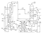
- FIG. 1 is a simplified schematic process flow diagram of an FCC unit, including an oil quench tower, used to crack light hydrocarbons, according to one embodiment of the invention.
- FIG. 2 is an enlarged elevation of a lower portion of the regenerator of FIG. 1 for regenerating catalyst in a light FCC unit using slurry of the fines from the filter backwash of the oil quench tower according to the present invention.
- FIG. 3 is a plan of the regenerator of FIG. 2 as seen along the lines 3 — 3 in FIG. 2 .
- FIG. 4 (prior art) is an enlarged elevation of a lower portion of a regenerator having a side entry for catalyst used for regenerating catalyst in a conventional side by side FCC unit.
- FIG. 5 is an enlarged elevation of a lower portion of another embodiment of a regenerator according to the present invention for regenerating catalyst in a light or conventional FCC unit in a side by side configuration.
- the present invention is a method and system for recovering fines from the light FCC effluent and regenerating spent catalyst.
- a light FCC unit or process is one in which the hydrocarbon feedstock to the FCC riser has a very low resid content such that there is insufficient carbon deposited on the catalyst to sustain combustion for regeneration without a supplemental fuel source, and there is insufficient fuel oil in the riser effluent for conventional slurry oil recovery, i.e. less than 2 weight percent of the hydrocarbons in the reactor effluent gases from the riser have an atmospheric boiling point above 550° F.(288° C.).
- the FCC process encompasses a fluidized catalytic reaction system, converting a light hydrocarbon feed stream preferably having a high olefin content to a product slate rich in propylene and ethylene.
- the typical propylene/ethylene product ratio from the reactor can be approximately 2.0.
- the FCC reactor is very flexible in that it can process many olefin-rich streams which may be available from an olefins plant or a refinery, such as, for example, olefins plant C 4 /C 5 streams, refinery C 4 's, light naphtha produced in thermal or catalytic cracking processes, or the like.
- a superheated feed typically at 800° F.
- a superheated feed is introduced via line 100 to the riser 102 where it is mixed with hot regenerated catalyst supplied via line 104 .
- steam can also be injected into the riser 102 at this point.
- Reaction conditions in the riser 102 are maintained as described in U.S. Pat. Nos. 5,043,522; 5,171,921; and 6,118,035; each of which is hereby incorporated herein by reference in its entirety.
- the hydrocarbon gases and catalyst flow upward in the riser 102 , where the cracking reactions take place.
- the hydrocarbon gases and catalyst are separated in a series of conventional cyclones 106 , 108 , and the product gases at a typical temperature of 1100–1200° F. are routed out of the top of the stripper vessel 110 via line 112 .
- the effluent gases in line 112 can be cooled to generate steam in a waste heat boiler (not shown), and then are routed to a quench tower 114 where entrained catalyst is washed from the gases by contact with circulating quench oil.
- Overhead vapor from the tower 114 in line 116 at a typical temperature of 200–400° F. is then routed to conventional product recovery facilities such as distillation towers (not shown) for recovery of ethylene, propylene and other products.
- Catalyst separated by the cyclones 106 , 108 is collected at the bottom of the stripper 110 and contacted with steam (not shown) to strip residual hydrocarbon gas from the catalyst.
- the steam and hydrocarbons exit the stripper 110 with the other effluent gases through the cyclone 108 and line 112 as previously mentioned.
- the catalyst then flows down through standpipe 118 into the subjacent regenerator 120 .
- the regenerator 120 the small amount of coke that has formed on the catalyst is burned in the dense phase bed 122 and catalyst activity is restored for recirculation to the riser 102 via line 104 as previously mentioned.
- additional fuel is necessary to complete the heat balance on the reactor system.
- the fuel is preferably in the form of fuel oil, e.g. pyrolysis fuel oil, that contains catalyst fines from the quench tower 114 as described in more detail below, but capability for adding fuel gas can also be provided to supplement the heating if desired.
- the slurry is continuously supplied to the regenerator 120 from the slurry surge drum 124 via line 126 , which is designed for mitigating potential erosion.
- Accessory systems include conventional FCC systems such as, for example, air supply, catalyst hoppers and flue gas handling and heat recovery.
- An air compressor (not shown) supplies air via line 128 for regeneration of the catalyst.
- An air heater (not shown) can be provided for startup.
- Fresh and spent catalyst hoppers (not shown) are provided for storage of makeup and used/equilibrium catalyst that is typically respectively added to or taken from the regenerator, as is well known in the art.
- catalyst is separated from the flue gas in one or more cyclones 130 .
- a conventional third stage separator cyclone (not shown) can be used to minimize catalyst losses.
- the flue gases are typically cooled by superheating high pressure steam and vented.
- Spent catalyst, including fines from the third stage separator contain no or only trace amounts of poisons found in typical refinery FCC catalyst due to the relatively cleaner feedstocks used in the light olefin FCC process, and can be used as an adjunct in concrete or brick manufacture or disposed in landfill.
- the quench tower 114 includes a vapor-liquid contacting zone 130 , which can include conventional packing or trays, disposed above a liquid holdup zone 132 . Effluent gas from line 112 is introduced below the contacting zone 130 .
- a recirculation loop 134 includes pump 136 , heat exchanger 138 and return line 140 to introduce a continuous supply of quench oil to liquid distributor 142 above the contacting zone 130 .
- the catalyst fines in the effluent gas are washed into the quench oil, and the effluent gas is cooled.
- the effluent gas typically enters the quench tower 114 at 800–1000° F., and exits at 200–400° F.
- the quench oil can be maintained in holdup zone 132 at a temperature of 350–700° F., and cooled to 300–550° F. in exchanger 138 against a feedstock stream or steam.
- the quench tower 114 can include a secondary cooling zone 144 above the primary contacting zone 130 , similarly configured with pumparound loop 146 that includes exchanger 148 for further cooling the quench oil to 200–450° F., for example.
- a portion of the quench oil from collection zone 150 can be introduced via line 152 into line 112 to provide initial cooling of the effluent gases in mixing zone 154 upstream from the quench tower 114 .
- 500–550° F. quench oil in line 152 can cool the effluent gases to 800–1000° F. in the mixing zone 154 .
- a filtration loop 156 includes pump 158 , filters 160 a , 160 b and line 162 for returning filtrate to the quench tower 114 , either directly or via the recirculation loop 134 .
- Backwash gaseous medium is provided via line 164 to pressurize and flush the collected fines into line 166 and slurry drum 124 .
- the backwash gaseous medium can be selected from an inert gas, air and fuel gas.
- One of the filters 160 a or 160 b is in filter mode, while the other is in backwash mode.
- valves 168 , 170 , 172 and 174 are open and valves 175 , 176 , 180 and 182 are closed when filter 160 a is filtering and filter 160 b is being backwashed; the valves are switched after the fines have accumulated in filter 160 a and it is ready for backwashing.
- the filtration is preferably continuous and should be at a rate that keeps the fines level from building to excessive levels in the quench oil, preferably no more than 0.5 weight percent fines, more preferably no more than 0.2 weight percent, and yet more preferably no more than 0.1 weight percent fines in the quench oil.
- a quench tower receiving 50 to 200 lbs/hr catalyst fines in the effluent gas, for example, 100 lbs/hr
- 50,000 lbs/hr of quench oil must be filtered in order to maintain a catalyst concentration of 0.2 weight percent in the recirculation loop 134
- the backwash contains a high concentration of catalyst fines, on the order of 10 to 20 weight percent. This concentration is reduced to a manageable level, for example, 2 to 4 weight percent, by dilution with fuel oil and/or circulating quench oil in the slurry drum 124 .
- the amount of dilution oil is preferably equal to that required for combustion in the regenerator. If the fines concentration is in excess of a manageable level, additional fuel oil and/or quench oil can be introduced to the slurry drum 124 and this excess can be recycled to the riser via line 127 .
- the compressed gas can conveniently pressurize the drum 124 so that it is not necessary to employ a pump to transfer the slurry into the regenerator 120 via line 126 .
- quench oil slurry from the drum 124 is supplied to the regenerator 120 for combustion to supply the heating requirements and return the catalyst to the regenerator-riser system; however, if there is excess slurry, it can also be introduced to the riser 102 via line 127 .
- the quench oil in the slurry supplied to the riser 102 is added to the effluent gases via cyclone 106 , 108 and subsequently condensed in the quench tower 114 , whereas the entrained catalyst is eventually transferred into the regenerator 120 with the other catalyst recovered from the cyclones 106 , 108 .
- the regenerator 120 there is a standpipe 118 and plug valve 200 .
- Spent catalyst flows down the standpipe 118 and passes through the catalyst plug valve 200 .
- the catalyst changes direction and flows upwardly through the annulus 202 of the spent catalyst centerwell 204 using a fluidization gas introduced via line 125 to distribution ring 204 b positioned in the centerwell 204 below the valve 200 .
- the fluidization medium or gas can be, for example, steam, an inert gas, and fuel gas.
- Slurry oil (line 126 ) and a fluidization gas (line 123 ) are introduced through nozzles 204 a .
- the fluidization gas facilitates dispersion and atomization of the slurry oil as it discharges into the catalyst in the centerwell 204 .
- the dispersion steam and the slurry oil which vaporizes on contact with the hot spent catalyst, provide additional fluidization for the catalyst. At this point, vaporization of the slurry oil is required.
- An oxygen-containing gas is preferably not used as the fluidization gas here in order to avoid, or at least minimize, combustion within the centerwell 204 .
- the catalyst is diverted outwardly into the dense phase bed 122 from the circular slot 206 defined by the upper terminus of the centerwell 204 and an outer periphery of annular plate 208 .
- the annular plate 208 is secured about the standpipe 118 and preferably has an outer diameter at least that of the centerwell 204 . In this manner the catalyst is distributed radially outwardly into the dense phase catalyst bed 122 well below its upper surface 209 .
- the dense fluidized bed 122 is aerated by air provided by an air grid that preferably takes the form of air distribution ring 210 .
- the ring 210 has a diameter between the outer diameter of the centerwell 204 and the outer diameter of the dense phase bed 122 in the regenerator 120 .
- the slurry oil and the carbon on the catalyst are burned to form CO 2 . It is important to introduce the slurry oil/catalyst mixture into the dense phase bed 122 in relatively close proximity to the air and below the upper surface 209 of the bed 122 to ensure good combustion and heat generation within the bed 122 .
- the regenerator 120 is operated at 1250 to 1350° F., preferably from 1275 to 1325° F.
- the convergence of the air from the ring 210 and the catalyst/oil mixture from the slot 206 at relatively high velocities within the dense phase bed 122 facilitates good mixing in a combustion zone within the bed 122 to provide uniform heating and regeneration of the catalyst.
- the regenerator bed should be designed for a superficial vapor velocity of between 0.5 and 7 ft/s, preferably between 1.5 and 5 ft/s, and more preferably between 2 and 3 ft/s.
- the volume of the bed 122 above the air ring 210 should be designed for sufficient residence time to ensure essentially complete regeneration of the catalyst.
- Off gas is conventionally recovered overhead from the regenerator 120 via separator cyclones 130 and an overhead line 212 (see FIG. 1 ). Since the regenerator 120 is operated in a complete combustion mode, there is generally no need for a CO burner to convert the CO to CO 2 before discharge to the atmosphere, but one can be included if desired. More heat of combustion is generated, and hence less fuel oil is needed, when complete combustion is achieved. Excess air is generally avoided, but as a practical matter a slight excess is needed to achieve complete combustion.
- the regenerator 120 can be operated with or without a CO promoter, typically a catalyst such as platinum, which is commonly added to promote the conversion of CO to CO 2 .
- a CO promoter typically a catalyst such as platinum, which is commonly added to promote the conversion of CO to CO 2 .
- FIG. 4 The lower portion of a prior art side by side conventional FCC regenerator is shown in FIG. 4 .
- Catalyst is fed to the regenerator via an angled pipe 414 , a catalyst slide valve 416 , and an inlet 420 .
- the ends of a pair of hydroclones 430 extend below the upper surface 209 of the dense bed 122 .
- Combustion air is fed into the dense bed 122 via an air feed apparatus 409 .
- the regenerator 400 shown in FIG. 5 is according to the present invention and is useful in a FCC unit having a side by side configuration and can be substituted for the regenerator shown in FIG. 4 .
- a regenerator 400 provides greater feed versatility to accept conventional or light feeds, since a fuel oil, quench oil or slurry oil feed capability is provided when processing light FCC feeds in order to provide the necessary heat of reaction.
- angled pipe 414 for catalyst feed no longer terminates at the inlet 420 as shown in FIG. 4 . Rather, angled pipe 414 is coupled via the catalyst slide valve 416 to angled pipe 417 that extends therefrom substantially to the vertical center axis of the regenerator 400 and has a vertical stand portion 418 extending therefrom into the centerwell 204 . A deflection plate 450 is located below the lower end of the stand portion 418 to redirect the catalyst flowing therethrough.
- the remaining components having like reference numerals are as in the previous figures.
- an FCC unit of side-by-side configuration having a conventional regenerator for example, the regenerator shown in FIG. 4
- the air supply assembly 460 would be removed.
- the centerwell 204 , fluidization medium distribution ring 204 b and fuel distribution nozzles 204 a would be installed at the interior base of the regenerator within the centerwell 204 .
- the air distribution pipe 210 would be installed around the centerwell 204 and below the radial slot 206 .
- the circular deflector plate 450 would be installed within the centerwell 204 .
- Pipe 417 with the standpipe portion 418 and annular plate 208 would be installed such that the end of the stand portion 418 extends into the centerwell 204 a sufficient distance above the deflector plate 450 to allow flow of the catalyst and provide adequate deflection of the catalyst flow direction for mixing the catalyst with the fuel oil vaporized within the centerwell 204 .
- the hydroclones 430 may or may not have to be replaced or reconditioned or repositioned within the regenerator 400 such that their ends extend below the upper surface 209 of the dense bed 122 .
Abstract
Description
Claims (19)
Priority Applications (11)
| Application Number | Priority Date | Filing Date | Title |
|---|---|---|---|
| US10/065,377 US7011740B2 (en) | 2002-10-10 | 2002-10-10 | Catalyst recovery from light olefin FCC effluent |
| CA2437651A CA2437651C (en) | 2002-10-10 | 2003-08-20 | Catalyst recovery from light olefin fcc effluent |
| SG200304859A SG111144A1 (en) | 2002-10-10 | 2003-08-28 | Catalyst recovery from light olefin fcc effluent |
| DE60333334T DE60333334D1 (en) | 2002-10-10 | 2003-09-25 | Recovery of the catalyst from a light olefin-containing FCC exhaust stream |
| ES03021732T ES2345042T3 (en) | 2002-10-10 | 2003-09-25 | RECOVERY OF THE FCC EFFLUENT CATALYST CONTAINING LIGHT OLEFINS. |
| EP09175966.2A EP2161322B1 (en) | 2002-10-10 | 2003-09-25 | Catalyst recovery from light olefin FCC effluent |
| EP03021732A EP1413621B1 (en) | 2002-10-10 | 2003-09-25 | Catalyst recovery from light olefin FCC effluent |
| JP2003350226A JP4351019B2 (en) | 2002-10-10 | 2003-10-09 | Catalyst recovery from light olefin FCC effluent |
| RU2003129991/04A RU2330059C2 (en) | 2002-10-10 | 2003-10-09 | Method of extracting catalyst from output stream of liquid phase catalytic cracking of light olefines |
| MXPA03009298A MXPA03009298A (en) | 2002-10-10 | 2003-10-10 | Catalyst recovery from light olefin fcc effluent. |
| CNB2003101006420A CN100537715C (en) | 2002-10-10 | 2003-10-10 | From the fluid catalystic cracking effluent, reclaim the system and method for catalyzer |
Applications Claiming Priority (1)
| Application Number | Priority Date | Filing Date | Title |
|---|---|---|---|
| US10/065,377 US7011740B2 (en) | 2002-10-10 | 2002-10-10 | Catalyst recovery from light olefin FCC effluent |
Publications (2)
| Publication Number | Publication Date |
|---|---|
| US20040069684A1 US20040069684A1 (en) | 2004-04-15 |
| US7011740B2 true US7011740B2 (en) | 2006-03-14 |
Family
ID=32067692
Family Applications (1)
| Application Number | Title | Priority Date | Filing Date |
|---|---|---|---|
| US10/065,377 Expired - Lifetime US7011740B2 (en) | 2002-10-10 | 2002-10-10 | Catalyst recovery from light olefin FCC effluent |
Country Status (10)
| Country | Link |
|---|---|
| US (1) | US7011740B2 (en) |
| EP (2) | EP1413621B1 (en) |
| JP (1) | JP4351019B2 (en) |
| CN (1) | CN100537715C (en) |
| CA (1) | CA2437651C (en) |
| DE (1) | DE60333334D1 (en) |
| ES (1) | ES2345042T3 (en) |
| MX (1) | MXPA03009298A (en) |
| RU (1) | RU2330059C2 (en) |
| SG (1) | SG111144A1 (en) |
Cited By (32)
| Publication number | Priority date | Publication date | Assignee | Title |
|---|---|---|---|---|
| US20080035527A1 (en) * | 2006-08-11 | 2008-02-14 | Kellogg Brown & Root Llc | Dual riser FCC reactor process with light and mixed light/heavy feeds |
| US20080114197A1 (en) * | 2004-04-15 | 2008-05-15 | Bjorklund Bradford L | Wet Scrubbing and Recycle of Effluent-Contaminating Catalyst Particles in an Oxygenate-to-Olefin Process |
| US20080223754A1 (en) * | 2007-03-15 | 2008-09-18 | Anand Subramanian | Systems and methods for residue upgrading |
| US20090178954A1 (en) * | 2007-09-27 | 2009-07-16 | Kanyuh Adam J | Process for Enhanced Olefin Production |
| CN101522864A (en) * | 2006-09-28 | 2009-09-02 | 环球油品公司 | Process for enhanced olefin production |
| US20090218255A1 (en) * | 2008-02-28 | 2009-09-03 | Alan Claude | Recycle of olefinic naphthas by removing aromatics |
| US7611622B2 (en) | 2006-12-29 | 2009-11-03 | Kellogg Brown & Root Llc | FCC process for converting C3/C4 feeds to olefins and aromatics |
| US7687677B1 (en) | 2006-09-29 | 2010-03-30 | Uop Llc | Process for recovering thermal energy from a reactor effluent stream |
| US8506795B2 (en) | 2010-06-04 | 2013-08-13 | Uop Llc | Process for fluid catalytic cracking |
| US8618012B2 (en) | 2010-04-09 | 2013-12-31 | Kellogg Brown & Root Llc | Systems and methods for regenerating a spent catalyst |
| US8618011B2 (en) | 2010-04-09 | 2013-12-31 | Kellogg Brown & Root Llc | Systems and methods for regenerating a spent catalyst |
| US8747759B2 (en) | 2011-12-12 | 2014-06-10 | Uop Llc | Process and apparatus for mixing two streams of catalyst |
| US8747657B2 (en) | 2011-12-12 | 2014-06-10 | Uop Llc | Process and apparatus for mixing two streams of catalyst |
| US8747758B2 (en) | 2011-12-12 | 2014-06-10 | Uop Llc | Process and apparatus for mixing two streams of catalyst |
| US8815166B2 (en) | 2012-03-20 | 2014-08-26 | Uop Llc | Process and apparatus for mixing two streams of catalyst |
| US8815082B2 (en) | 2011-12-12 | 2014-08-26 | Uop Llc | Process and apparatus for mixing two streams of catalyst |
| US8889942B2 (en) | 2010-12-23 | 2014-11-18 | Kellogg Brown & Root Llc | Integrated light olefin separation/cracking process |
| US8916099B2 (en) | 2012-03-20 | 2014-12-23 | Uop Llc | Process and apparatus for mixing two streams of catalyst |
| US8932452B2 (en) | 2012-01-11 | 2015-01-13 | Cameron International Corporation | Method for separating entrained catalyst and catalyst fines from slurry oil |
| US8936758B2 (en) | 2012-03-20 | 2015-01-20 | Uop Llc | Process and apparatus for mixing two streams of catalyst |
| US9205394B2 (en) | 2014-03-31 | 2015-12-08 | Uop Llc | Process and apparatus for distributing fluidizing gas to an FCC riser |
| US9376633B2 (en) | 2014-03-31 | 2016-06-28 | Uop Llc | Process and apparatus for distributing fluidizing gas to an FCC riser |
| US9375695B2 (en) | 2012-03-20 | 2016-06-28 | Uop Llc | Process and apparatus for mixing two streams of catalyst |
| RU2593996C2 (en) * | 2012-02-23 | 2016-08-10 | КЕЛЛОГГ БРАУН ЭНД РУТ ЭлЭлСи | Mixing feed reservoir system |
| US9745519B2 (en) | 2012-08-22 | 2017-08-29 | Kellogg Brown & Root Llc | FCC process using a modified catalyst |
| US9969662B2 (en) | 2012-04-05 | 2018-05-15 | Linde Aktiengesellschaft | Method for separating olefins with gentle cleavage |
| CN108061297A (en) * | 2017-11-21 | 2018-05-22 | 中国能源建设集团华东电力试验研究院有限公司 | 300MW circulating fluidized bed boilers and its control method |
| US10246645B2 (en) | 2014-09-29 | 2019-04-02 | Uop Llc | Methods for reducing flue gas emissions from fluid catalytic cracking unit regenerators |
| WO2018236630A3 (en) * | 2017-06-19 | 2020-01-16 | Dow Global Technologies Llc | Reactor systems comprising fluid recycling |
| WO2020191192A1 (en) * | 2019-03-21 | 2020-09-24 | Kellogg Brown & Root Llc | Processes for catalytic paraffin dehydrogenation and catalyst recovery |
| US11117108B2 (en) * | 2019-09-13 | 2021-09-14 | Kellogg Brown & Root Llc | Use of a fuel oil wash to remove catalyst from a fluidized-bed propane dehydrogenation reactor effluent |
| US20220250049A1 (en) * | 2019-03-21 | 2022-08-11 | Kellogg Brown & Root Llc | Processes for catalytic paraffin dehydrogenation and catalyst recovery |
Families Citing this family (22)
| Publication number | Priority date | Publication date | Assignee | Title |
|---|---|---|---|---|
| CN1325607C (en) * | 2005-12-07 | 2007-07-11 | 江苏工业学院 | Filter device for reaction system of petroleum catalytic cracking experiment apparatus |
| CN100386127C (en) * | 2006-03-24 | 2008-05-07 | 天津大学 | Decompression tower bottom coke inhibiting device and its uses |
| US7572364B2 (en) * | 2006-04-27 | 2009-08-11 | Intercat Equipment, Inc. | Fluid catalytic cracking system with fines addition system |
| JP5089227B2 (en) * | 2007-04-12 | 2012-12-05 | 住友化学株式会社 | Filtration method |
| US8137535B2 (en) * | 2008-01-29 | 2012-03-20 | Kellogg Brown & Root Llc | Method for adjusting catalyst activity |
| US8735642B2 (en) * | 2008-06-30 | 2014-05-27 | Uop Llc | Two stage contact cooler design for hot water generation |
| US8383052B2 (en) | 2010-04-16 | 2013-02-26 | Kellogg Brown & Root Llc | System for a heat balanced FCC forlight hydrocarbon feeds |
| CN102002385B (en) * | 2010-12-07 | 2014-08-06 | 上海蓝科石化工程技术有限公司 | Device and method for separating residue from catalytic cracking oil slurry |
| US8877997B2 (en) * | 2010-12-20 | 2014-11-04 | Uop Llc | Quench tower catalyst recovery |
| KR102549756B1 (en) * | 2017-02-28 | 2023-06-29 | 부르크하르트 콤프레션 아게 | Apparatus and method for separating lubricants from gas streams and systems and methods for compressing combustible gases |
| CN107597201B (en) * | 2017-09-13 | 2019-10-08 | 上海华畅环保设备发展有限公司 | Oil-containing outlet catalyst treatment and sorting reuse method and device |
| US11279885B2 (en) | 2018-05-10 | 2022-03-22 | Korea Institute Of Machinery & Materials | Catalyst regenerator |
| KR102232804B1 (en) * | 2018-12-21 | 2021-03-26 | 한국기계연구원 | Fluidized bed catalyst regenerator |
| EP3797143A4 (en) * | 2018-05-23 | 2022-03-02 | Kellogg Brown & Root LLC | Regulatory controller for usage in a catalytic olefins unit |
| US11118117B2 (en) | 2019-05-23 | 2021-09-14 | Kellogg Brown & Root Llc | Regulatory controller for usage in a catalytic olefins |
| WO2019226854A1 (en) * | 2018-05-23 | 2019-11-28 | Kellogg Brown & Root Llc | Regulatory controller for usage in a catalytic olefins unit |
| CN109647544B (en) * | 2019-01-03 | 2021-06-11 | 飞潮(无锡)过滤技术有限公司 | Process for recovering waste copper bismuth catalyst by dry-wet composite regeneration |
| WO2020191190A1 (en) * | 2019-03-21 | 2020-09-24 | Kellogg Brown & Root Llc | System and method for catalyst removal from mto effluent |
| US11725153B2 (en) * | 2020-04-17 | 2023-08-15 | Uop Llc | Process and apparatus for recovering catalyst from a product stream |
| CN114433250A (en) * | 2020-10-16 | 2022-05-06 | 中国石油化工股份有限公司 | Slurry recovery device, slurry preparation system and slurry recovery method |
| US20230133426A1 (en) * | 2021-11-02 | 2023-05-04 | Uop Llc | Process and apparatus for reacting feed with cooled regenerated catalyst |
| WO2023212497A1 (en) * | 2022-04-25 | 2023-11-02 | Kellogg Brown & Root Llc | Processes for catalytic paraffin dehydrogenation and catalyst recovery |
Citations (18)
| Publication number | Priority date | Publication date | Assignee | Title |
|---|---|---|---|---|
| US2663676A (en) | 1951-03-16 | 1953-12-22 | Standard Oil Dev Co | Catalyst recovery |
| US3221076A (en) | 1959-12-22 | 1965-11-30 | Basf Ag | Cracking of hydrocarbons |
| US3238271A (en) | 1960-03-16 | 1966-03-01 | Basf Ag | Cracking of hydrocarbons to gaseous olefines |
| US3338821A (en) | 1964-11-18 | 1967-08-29 | Phillips Petroleum Co | Quenching of catalytic cracking reactor vapors in feed line to fractionator |
| US4285805A (en) * | 1980-03-20 | 1981-08-25 | Phillips Petroleum Company | Time-delay process and control system for electrostatic filter |
| US5043522A (en) | 1989-04-25 | 1991-08-27 | Arco Chemical Technology, Inc. | Production of olefins from a mixture of Cu+ olefins and paraffins |
| US5073249A (en) * | 1989-11-21 | 1991-12-17 | Mobil Oil Corporation | Heavy oil catalytic cracking process and apparatus |
| US5167795A (en) | 1988-01-28 | 1992-12-01 | Stone & Webster Engineering Corp. | Process for the production of olefins and aromatics |
| US5171921A (en) | 1991-04-26 | 1992-12-15 | Arco Chemical Technology, L.P. | Production of olefins |
| US5220093A (en) | 1992-04-03 | 1993-06-15 | Stone & Webster Engineering Corporation | Process for production of olefins from mixtures of light paraffins |
| US5234578A (en) | 1988-08-26 | 1993-08-10 | Uop | Fluidized catalytic cracking process utilizing a high temperature reactor |
| US5271826A (en) | 1988-03-03 | 1993-12-21 | Mobil Oil Corporation | Catalytic cracking of coke producing hydrocarbons |
| US5597537A (en) | 1993-09-24 | 1997-01-28 | Uop | FCC feed contacting with catalyst recycle reactor |
| US5730859A (en) | 1992-08-20 | 1998-03-24 | Stone & Webster Engineering Corporation | Process for catalytically cracking paraffin rich feedstocks comprising high and low concarbon components |
| US5965012A (en) | 1997-12-05 | 1999-10-12 | Uop Llc | FCC process with short primary contacting and controlled secondary contacting |
| US6113776A (en) | 1998-06-08 | 2000-09-05 | Uop Llc | FCC process with high temperature cracking zone |
| US6139720A (en) | 1999-02-19 | 2000-10-31 | Uop Llc | FCC process with carbon monoxide management and hot stripping |
| US6162402A (en) | 1997-12-05 | 2000-12-19 | Uop Llc | FCC apparatus with combined regenerator stripper and catalyst blending |
Family Cites Families (1)
| Publication number | Priority date | Publication date | Assignee | Title |
|---|---|---|---|---|
| US6118035A (en) | 1998-05-05 | 2000-09-12 | Exxon Research And Engineering Co. | Process for selectively producing light olefins in a fluid catalytic cracking process from a naphtha/steam feed |
-
2002
- 2002-10-10 US US10/065,377 patent/US7011740B2/en not_active Expired - Lifetime
-
2003
- 2003-08-20 CA CA2437651A patent/CA2437651C/en not_active Expired - Fee Related
- 2003-08-28 SG SG200304859A patent/SG111144A1/en unknown
- 2003-09-25 EP EP03021732A patent/EP1413621B1/en not_active Expired - Lifetime
- 2003-09-25 DE DE60333334T patent/DE60333334D1/en not_active Expired - Lifetime
- 2003-09-25 EP EP09175966.2A patent/EP2161322B1/en not_active Expired - Lifetime
- 2003-09-25 ES ES03021732T patent/ES2345042T3/en not_active Expired - Lifetime
- 2003-10-09 JP JP2003350226A patent/JP4351019B2/en not_active Expired - Lifetime
- 2003-10-09 RU RU2003129991/04A patent/RU2330059C2/en active
- 2003-10-10 MX MXPA03009298A patent/MXPA03009298A/en active IP Right Grant
- 2003-10-10 CN CNB2003101006420A patent/CN100537715C/en not_active Expired - Lifetime
Patent Citations (18)
| Publication number | Priority date | Publication date | Assignee | Title |
|---|---|---|---|---|
| US2663676A (en) | 1951-03-16 | 1953-12-22 | Standard Oil Dev Co | Catalyst recovery |
| US3221076A (en) | 1959-12-22 | 1965-11-30 | Basf Ag | Cracking of hydrocarbons |
| US3238271A (en) | 1960-03-16 | 1966-03-01 | Basf Ag | Cracking of hydrocarbons to gaseous olefines |
| US3338821A (en) | 1964-11-18 | 1967-08-29 | Phillips Petroleum Co | Quenching of catalytic cracking reactor vapors in feed line to fractionator |
| US4285805A (en) * | 1980-03-20 | 1981-08-25 | Phillips Petroleum Company | Time-delay process and control system for electrostatic filter |
| US5167795A (en) | 1988-01-28 | 1992-12-01 | Stone & Webster Engineering Corp. | Process for the production of olefins and aromatics |
| US5271826A (en) | 1988-03-03 | 1993-12-21 | Mobil Oil Corporation | Catalytic cracking of coke producing hydrocarbons |
| US5234578A (en) | 1988-08-26 | 1993-08-10 | Uop | Fluidized catalytic cracking process utilizing a high temperature reactor |
| US5043522A (en) | 1989-04-25 | 1991-08-27 | Arco Chemical Technology, Inc. | Production of olefins from a mixture of Cu+ olefins and paraffins |
| US5073249A (en) * | 1989-11-21 | 1991-12-17 | Mobil Oil Corporation | Heavy oil catalytic cracking process and apparatus |
| US5171921A (en) | 1991-04-26 | 1992-12-15 | Arco Chemical Technology, L.P. | Production of olefins |
| US5220093A (en) | 1992-04-03 | 1993-06-15 | Stone & Webster Engineering Corporation | Process for production of olefins from mixtures of light paraffins |
| US5730859A (en) | 1992-08-20 | 1998-03-24 | Stone & Webster Engineering Corporation | Process for catalytically cracking paraffin rich feedstocks comprising high and low concarbon components |
| US5597537A (en) | 1993-09-24 | 1997-01-28 | Uop | FCC feed contacting with catalyst recycle reactor |
| US5965012A (en) | 1997-12-05 | 1999-10-12 | Uop Llc | FCC process with short primary contacting and controlled secondary contacting |
| US6162402A (en) | 1997-12-05 | 2000-12-19 | Uop Llc | FCC apparatus with combined regenerator stripper and catalyst blending |
| US6113776A (en) | 1998-06-08 | 2000-09-05 | Uop Llc | FCC process with high temperature cracking zone |
| US6139720A (en) | 1999-02-19 | 2000-10-31 | Uop Llc | FCC process with carbon monoxide management and hot stripping |
Cited By (41)
| Publication number | Priority date | Publication date | Assignee | Title |
|---|---|---|---|---|
| US20080114197A1 (en) * | 2004-04-15 | 2008-05-15 | Bjorklund Bradford L | Wet Scrubbing and Recycle of Effluent-Contaminating Catalyst Particles in an Oxygenate-to-Olefin Process |
| US7491315B2 (en) | 2006-08-11 | 2009-02-17 | Kellogg Brown & Root Llc | Dual riser FCC reactor process with light and mixed light/heavy feeds |
| US20080035527A1 (en) * | 2006-08-11 | 2008-02-14 | Kellogg Brown & Root Llc | Dual riser FCC reactor process with light and mixed light/heavy feeds |
| CN101522864A (en) * | 2006-09-28 | 2009-09-02 | 环球油品公司 | Process for enhanced olefin production |
| US7687677B1 (en) | 2006-09-29 | 2010-03-30 | Uop Llc | Process for recovering thermal energy from a reactor effluent stream |
| US7611622B2 (en) | 2006-12-29 | 2009-11-03 | Kellogg Brown & Root Llc | FCC process for converting C3/C4 feeds to olefins and aromatics |
| US20080223754A1 (en) * | 2007-03-15 | 2008-09-18 | Anand Subramanian | Systems and methods for residue upgrading |
| US8608942B2 (en) | 2007-03-15 | 2013-12-17 | Kellogg Brown & Root Llc | Systems and methods for residue upgrading |
| US8044254B2 (en) * | 2007-09-27 | 2011-10-25 | Uop Llc | Process for enhanced olefin production |
| US20090178954A1 (en) * | 2007-09-27 | 2009-07-16 | Kanyuh Adam J | Process for Enhanced Olefin Production |
| US20090218255A1 (en) * | 2008-02-28 | 2009-09-03 | Alan Claude | Recycle of olefinic naphthas by removing aromatics |
| US7883618B2 (en) | 2008-02-28 | 2011-02-08 | Kellogg Brown & Root Llc | Recycle of olefinic naphthas by removing aromatics |
| US8618012B2 (en) | 2010-04-09 | 2013-12-31 | Kellogg Brown & Root Llc | Systems and methods for regenerating a spent catalyst |
| US8618011B2 (en) | 2010-04-09 | 2013-12-31 | Kellogg Brown & Root Llc | Systems and methods for regenerating a spent catalyst |
| US8506795B2 (en) | 2010-06-04 | 2013-08-13 | Uop Llc | Process for fluid catalytic cracking |
| US8889942B2 (en) | 2010-12-23 | 2014-11-18 | Kellogg Brown & Root Llc | Integrated light olefin separation/cracking process |
| US8747758B2 (en) | 2011-12-12 | 2014-06-10 | Uop Llc | Process and apparatus for mixing two streams of catalyst |
| US8747657B2 (en) | 2011-12-12 | 2014-06-10 | Uop Llc | Process and apparatus for mixing two streams of catalyst |
| US8815082B2 (en) | 2011-12-12 | 2014-08-26 | Uop Llc | Process and apparatus for mixing two streams of catalyst |
| US8747759B2 (en) | 2011-12-12 | 2014-06-10 | Uop Llc | Process and apparatus for mixing two streams of catalyst |
| US8932452B2 (en) | 2012-01-11 | 2015-01-13 | Cameron International Corporation | Method for separating entrained catalyst and catalyst fines from slurry oil |
| US9446364B2 (en) | 2012-02-23 | 2016-09-20 | Kellogg Brown & Root Llc | Surge drum mixing system |
| RU2593996C2 (en) * | 2012-02-23 | 2016-08-10 | КЕЛЛОГГ БРАУН ЭНД РУТ ЭлЭлСи | Mixing feed reservoir system |
| US8936758B2 (en) | 2012-03-20 | 2015-01-20 | Uop Llc | Process and apparatus for mixing two streams of catalyst |
| US8916099B2 (en) | 2012-03-20 | 2014-12-23 | Uop Llc | Process and apparatus for mixing two streams of catalyst |
| US8815166B2 (en) | 2012-03-20 | 2014-08-26 | Uop Llc | Process and apparatus for mixing two streams of catalyst |
| US9375695B2 (en) | 2012-03-20 | 2016-06-28 | Uop Llc | Process and apparatus for mixing two streams of catalyst |
| US9969662B2 (en) | 2012-04-05 | 2018-05-15 | Linde Aktiengesellschaft | Method for separating olefins with gentle cleavage |
| US9745519B2 (en) | 2012-08-22 | 2017-08-29 | Kellogg Brown & Root Llc | FCC process using a modified catalyst |
| US9205394B2 (en) | 2014-03-31 | 2015-12-08 | Uop Llc | Process and apparatus for distributing fluidizing gas to an FCC riser |
| US9376633B2 (en) | 2014-03-31 | 2016-06-28 | Uop Llc | Process and apparatus for distributing fluidizing gas to an FCC riser |
| US10246645B2 (en) | 2014-09-29 | 2019-04-02 | Uop Llc | Methods for reducing flue gas emissions from fluid catalytic cracking unit regenerators |
| EP4046702A1 (en) * | 2017-06-19 | 2022-08-24 | Dow Global Technologies Llc | Reactor systems comprising fluid recycling |
| WO2018236630A3 (en) * | 2017-06-19 | 2020-01-16 | Dow Global Technologies Llc | Reactor systems comprising fluid recycling |
| US11059013B2 (en) | 2017-06-19 | 2021-07-13 | Dow Global Technologies Llc | Reactor systems comprising fluid recycling |
| US11478769B2 (en) | 2017-06-19 | 2022-10-25 | Dow Global Technologies Llc | Reactor systems comprising fluid recycling |
| CN108061297A (en) * | 2017-11-21 | 2018-05-22 | 中国能源建设集团华东电力试验研究院有限公司 | 300MW circulating fluidized bed boilers and its control method |
| WO2020191192A1 (en) * | 2019-03-21 | 2020-09-24 | Kellogg Brown & Root Llc | Processes for catalytic paraffin dehydrogenation and catalyst recovery |
| US20220250049A1 (en) * | 2019-03-21 | 2022-08-11 | Kellogg Brown & Root Llc | Processes for catalytic paraffin dehydrogenation and catalyst recovery |
| EP3941893A4 (en) * | 2019-03-21 | 2023-01-11 | Kellogg Brown & Root LLC | Processes for catalytic paraffin dehydrogenation and catalyst recovery |
| US11117108B2 (en) * | 2019-09-13 | 2021-09-14 | Kellogg Brown & Root Llc | Use of a fuel oil wash to remove catalyst from a fluidized-bed propane dehydrogenation reactor effluent |
Also Published As
| Publication number | Publication date |
|---|---|
| MXPA03009298A (en) | 2004-04-28 |
| JP2004131736A (en) | 2004-04-30 |
| EP1413621A1 (en) | 2004-04-28 |
| ES2345042T3 (en) | 2010-09-14 |
| CA2437651A1 (en) | 2004-04-10 |
| DE60333334D1 (en) | 2010-08-26 |
| US20040069684A1 (en) | 2004-04-15 |
| CA2437651C (en) | 2013-02-19 |
| EP1413621B1 (en) | 2010-07-14 |
| EP2161322B1 (en) | 2014-08-27 |
| JP4351019B2 (en) | 2009-10-28 |
| SG111144A1 (en) | 2005-05-30 |
| RU2003129991A (en) | 2005-03-27 |
| RU2330059C2 (en) | 2008-07-27 |
| CN1497040A (en) | 2004-05-19 |
| CN100537715C (en) | 2009-09-09 |
| EP2161322A1 (en) | 2010-03-10 |
Similar Documents
| Publication | Publication Date | Title |
|---|---|---|
| US7011740B2 (en) | Catalyst recovery from light olefin FCC effluent | |
| US7153479B2 (en) | Catalyst regenerator with a centerwell | |
| EP0848051B1 (en) | Fluid catalytic cracking of hydrocarbons with integrated apparatus for separating and stripping catalyst | |
| US4090948A (en) | Catalytic cracking process | |
| US5009769A (en) | Process for catalytic cracking of hydrocarbons | |
| US6616900B1 (en) | FCC process with two zone short contact time reaction conduit | |
| US4331533A (en) | Method and apparatus for cracking residual oils | |
| US4419221A (en) | Cracking with short contact time and high temperatures | |
| US5582712A (en) | Downflow FCC reaction arrangement with upflow regeneration | |
| US4478708A (en) | Method and apparatus for separating fluidized solid particles suspended in gasiform material | |
| WO2007094770A1 (en) | Apparatus and process for regenerating catalyst | |
| US6039863A (en) | Fluidized particle contacting process with elongated combustor | |
| JPH0623301A (en) | Riser cyclone separator | |
| KR930011920B1 (en) | Process for catalystic cracking of hydrocarbons | |
| US4428822A (en) | Fluid catalytic cracking | |
| EP0309244B1 (en) | Fluid catalytic cracking regeneration with spent catalyst separator | |
| JPH03207795A (en) | Consolidated paraffin modification and contact decomposition | |
| US6723227B1 (en) | Fluidized catalytic cracking process | |
| EP0129621B1 (en) | Apparatus and process for fluidized catalytic cracking of hydrocarbons and catalyst regeneration | |
| US4397816A (en) | Apparatus for regeneration of spent cracking catalyst | |
| CA1259579A (en) | Method and apparatus for cracking residual oils | |
| AU724751B2 (en) | Fluid catalytic cracking of hydrocarbons with integrated apparatus for separating and stripping catalyst |
Legal Events
| Date | Code | Title | Description |
|---|---|---|---|
| AS | Assignment |
Owner name: KELLOGG BROWN & ROOT, INC., TEXAS Free format text: ASSIGNMENT OF ASSIGNORS INTEREST;ASSIGNORS:TALLMAN, MICHAEL J.;PETERSON, ROBERT B.;GILBERT, MAUREEN F.;REEL/FRAME:013164/0663 Effective date: 20021007 |
|
| STCF | Information on status: patent grant |
Free format text: PATENTED CASE |
|
| FPAY | Fee payment |
Year of fee payment: 4 |
|
| FPAY | Fee payment |
Year of fee payment: 8 |
|
| MAFP | Maintenance fee payment |
Free format text: PAYMENT OF MAINTENANCE FEE, 12TH YEAR, LARGE ENTITY (ORIGINAL EVENT CODE: M1553) Year of fee payment: 12 |
|
| AS | Assignment |
Owner name: BANK OF AMERICA, N.A., AS ADMINISTRATIVE AGENT, NORTH CAROLINA Free format text: SECURITY INTEREST;ASSIGNOR:KELLOGG BROWN & ROOT LLC;REEL/FRAME:046022/0413 Effective date: 20180425 Owner name: BANK OF AMERICA, N.A., AS ADMINISTRATIVE AGENT, NO Free format text: SECURITY INTEREST;ASSIGNOR:KELLOGG BROWN & ROOT LLC;REEL/FRAME:046022/0413 Effective date: 20180425 |