EP2833795B2 - Probenentnahme-, verdünnungs- und ausgabevorrichtung - Google Patents
Probenentnahme-, verdünnungs- und ausgabevorrichtung Download PDFInfo
- Publication number
- EP2833795B2 EP2833795B2 EP13701953.5A EP13701953A EP2833795B2 EP 2833795 B2 EP2833795 B2 EP 2833795B2 EP 13701953 A EP13701953 A EP 13701953A EP 2833795 B2 EP2833795 B2 EP 2833795B2
- Authority
- EP
- European Patent Office
- Prior art keywords
- sample
- pin
- container
- tube
- handle
- Prior art date
- Legal status (The legal status is an assumption and is not a legal conclusion. Google has not performed a legal analysis and makes no representation as to the accuracy of the status listed.)
- Active
Links
Images


Classifications
-
- G—PHYSICS
- G01—MEASURING; TESTING
- G01N—INVESTIGATING OR ANALYSING MATERIALS BY DETERMINING THEIR CHEMICAL OR PHYSICAL PROPERTIES
- G01N1/00—Sampling; Preparing specimens for investigation
- G01N1/28—Preparing specimens for investigation including physical details of (bio-)chemical methods covered elsewhere, e.g. G01N33/50, C12Q
- G01N1/38—Diluting, dispersing or mixing samples
-
- A—HUMAN NECESSITIES
- A61—MEDICAL OR VETERINARY SCIENCE; HYGIENE
- A61B—DIAGNOSIS; SURGERY; IDENTIFICATION
- A61B10/00—Instruments for taking body samples for diagnostic purposes; Other methods or instruments for diagnosis, e.g. for vaccination diagnosis, sex determination or ovulation-period determination; Throat striking implements
- A61B10/0038—Devices for taking faeces samples; Faecal examination devices
-
- B—PERFORMING OPERATIONS; TRANSPORTING
- B01—PHYSICAL OR CHEMICAL PROCESSES OR APPARATUS IN GENERAL
- B01L—CHEMICAL OR PHYSICAL LABORATORY APPARATUS FOR GENERAL USE
- B01L3/00—Containers or dishes for laboratory use, e.g. laboratory glassware; Droppers
- B01L3/50—Containers for the purpose of retaining a material to be analysed, e.g. test tubes
- B01L3/502—Containers for the purpose of retaining a material to be analysed, e.g. test tubes with fluid transport, e.g. in multi-compartment structures
-
- A—HUMAN NECESSITIES
- A61—MEDICAL OR VETERINARY SCIENCE; HYGIENE
- A61B—DIAGNOSIS; SURGERY; IDENTIFICATION
- A61B10/00—Instruments for taking body samples for diagnostic purposes; Other methods or instruments for diagnosis, e.g. for vaccination diagnosis, sex determination or ovulation-period determination; Throat striking implements
- A61B10/0096—Casings for storing test samples
-
- B—PERFORMING OPERATIONS; TRANSPORTING
- B01—PHYSICAL OR CHEMICAL PROCESSES OR APPARATUS IN GENERAL
- B01L—CHEMICAL OR PHYSICAL LABORATORY APPARATUS FOR GENERAL USE
- B01L2200/00—Solutions for specific problems relating to chemical or physical laboratory apparatus
- B01L2200/06—Fluid handling related problems
- B01L2200/0689—Sealing
-
- B—PERFORMING OPERATIONS; TRANSPORTING
- B01—PHYSICAL OR CHEMICAL PROCESSES OR APPARATUS IN GENERAL
- B01L—CHEMICAL OR PHYSICAL LABORATORY APPARATUS FOR GENERAL USE
- B01L2200/00—Solutions for specific problems relating to chemical or physical laboratory apparatus
- B01L2200/16—Reagents, handling or storing thereof
-
- B—PERFORMING OPERATIONS; TRANSPORTING
- B01—PHYSICAL OR CHEMICAL PROCESSES OR APPARATUS IN GENERAL
- B01L—CHEMICAL OR PHYSICAL LABORATORY APPARATUS FOR GENERAL USE
- B01L2300/00—Additional constructional details
- B01L2300/06—Auxiliary integrated devices, integrated components
- B01L2300/0609—Holders integrated in container to position an object
-
- B—PERFORMING OPERATIONS; TRANSPORTING
- B01—PHYSICAL OR CHEMICAL PROCESSES OR APPARATUS IN GENERAL
- B01L—CHEMICAL OR PHYSICAL LABORATORY APPARATUS FOR GENERAL USE
- B01L2300/00—Additional constructional details
- B01L2300/06—Auxiliary integrated devices, integrated components
- B01L2300/0681—Filter
-
- B—PERFORMING OPERATIONS; TRANSPORTING
- B01—PHYSICAL OR CHEMICAL PROCESSES OR APPARATUS IN GENERAL
- B01L—CHEMICAL OR PHYSICAL LABORATORY APPARATUS FOR GENERAL USE
- B01L2300/00—Additional constructional details
- B01L2300/08—Geometry, shape and general structure
- B01L2300/0861—Configuration of multiple channels and/or chambers in a single devices
- B01L2300/087—Multiple sequential chambers
-
- B—PERFORMING OPERATIONS; TRANSPORTING
- B01—PHYSICAL OR CHEMICAL PROCESSES OR APPARATUS IN GENERAL
- B01L—CHEMICAL OR PHYSICAL LABORATORY APPARATUS FOR GENERAL USE
- B01L2400/00—Moving or stopping fluids
- B01L2400/06—Valves, specific forms thereof
- B01L2400/0633—Valves, specific forms thereof with moving parts
- B01L2400/0644—Valves, specific forms thereof with moving parts rotary valves
-
- B—PERFORMING OPERATIONS; TRANSPORTING
- B01—PHYSICAL OR CHEMICAL PROCESSES OR APPARATUS IN GENERAL
- B01L—CHEMICAL OR PHYSICAL LABORATORY APPARATUS FOR GENERAL USE
- B01L2400/00—Moving or stopping fluids
- B01L2400/06—Valves, specific forms thereof
- B01L2400/0677—Valves, specific forms thereof phase change valves; Meltable, freezing, dissolvable plugs; Destructible barriers
- B01L2400/0683—Valves, specific forms thereof phase change valves; Meltable, freezing, dissolvable plugs; Destructible barriers mechanically breaking a wall or membrane within a channel or chamber
-
- G—PHYSICS
- G01—MEASURING; TESTING
- G01N—INVESTIGATING OR ANALYSING MATERIALS BY DETERMINING THEIR CHEMICAL OR PHYSICAL PROPERTIES
- G01N1/00—Sampling; Preparing specimens for investigation
- G01N1/28—Preparing specimens for investigation including physical details of (bio-)chemical methods covered elsewhere, e.g. G01N33/50, C12Q
- G01N1/38—Diluting, dispersing or mixing samples
- G01N2001/382—Diluting, dispersing or mixing samples using pistons of different sections
-
- G—PHYSICS
- G01—MEASURING; TESTING
- G01N—INVESTIGATING OR ANALYSING MATERIALS BY DETERMINING THEIR CHEMICAL OR PHYSICAL PROPERTIES
- G01N1/00—Sampling; Preparing specimens for investigation
- G01N1/28—Preparing specimens for investigation including physical details of (bio-)chemical methods covered elsewhere, e.g. G01N33/50, C12Q
- G01N1/38—Diluting, dispersing or mixing samples
- G01N2001/386—Other diluting or mixing processes
Definitions
- the invention refers to a stool extracting, diluting and discharging device and, in particular, to a sample transferring device. Furthermore, the invention refers to a method for collecting, diluting, mixing and discharging a stool sample.
- EP 1 986 006 A1 discloses a device according to the preamble of claim 1.
- DE 10 2007 057 760 B3 discloses a device for collecting and dissolving a pastry sample.
- the sample pin of this device has a hollow end part for collecting the sample.
- the end part comprises further windows or openings in its side wall.
- US 7,048,693 B2 , EP 1384442 B1 and US 2006/0210448 A1 show a specimen collection, storage and transport device with a sample pin for collecting the specimen.
- This sample pin has a handle and an elongated pin with a spiral-shaped end. This end is put into a sample to be probed, pulled out again and shoved into the corresponding tube.
- the tube is divided into two sections, an upper section and a lower section.
- the separation wall between these two sections comprises a hole through which the sample pin and in particular the spiral-shaped end is pushed and a certain amount of the collected sample can be brought into the second section.
- This second section is filled with a solution.
- the discharge port comprises a breakable closure, which is opened by breaking off the tip of the discharge port. After that, the diluted sample can be discharged through the broken tip by pressing the body of the tube.
- the samples are not always of the same structure. That is, the samples can vary from a very liquid state to a very solid state.
- the samples can vary from a very liquid state to a very solid state.
- the spiral-shaped end of the sample pin is not ideal of keeping the sample on the sample pin, because a liquid sample will drop off the sample pin. Therefore, it is very difficult to get a predetermined amount of such a sample into the tube.
- a further disadvantage of the prior art is that discharging of the diluted sample via the breakable closure is difficult to control. By or after opening the discharge port it may happen that pressure is brought onto the tube and some of the diluted sample is discharged by accident. Finally, once opened, the types of prior art tubes cannot be closed again and, thus, it is very difficult or impossible to store them and use again for a second test and the like.
- a pipette is generally used to transfer a predetermined volume of the diluted sample contained in the tube.
- the tube has to be opened and the pipette has to be inserted into the tube.
- this is a possible source for contamination of the sample and also hygienically not free of risks. Therefore, the above mentioned devices are even not suitable for near patient testing.
- An aspect of the invention is a tube for mixing, diluting, preserving and discharging a sample
- the tube comprises a hollow first container for receiving and/or storing a solution, the first container having first and second ends, wherein the first end has a first through-hole suitable for inserting a sample pin having a shape matching to the through-hole, the second end has a discharge port suitable for discharging a diluted sample
- the hollow first container comprises locking means for locking a sample pin in a first position located at the first end of the hollow first container. This ensures a safe delivery of a properly closed tube.
- the tube further comprises second locking means for locking the sample pin in a second position located further in insertion direction than the first position. The second locking means prevent retraction of the sample pin. In addition to a safe delivery and due to the hygienically aspect, after use the second locking means prohibits that the tube is opened by accident or normal handling.
- the first locking means can comprise a rib or a groove disposed on a circumferential portion of the first end of the first container, preferably not on the complete circumference (although it is possible).
- the second locking means can comprise a rib or a groove disposed on the circumference of the accommodating part, preferably around the complete circumference.
- Such a tube can further comprise a sample pin having an elongated pin, a handle located at a proximal end of the elongated pin, and at least one recess with a predetermined volume formed in a distal portion of the elongated pin, wherein the handle comprises at least one locking portion corresponding to the first and/or second locking means.
- the sample pin can further have a gripping portion, particularly formed as pressing portion that serves to deform the handle to unlock the sample pin from the first position. This is a convenient but also secure way to firstly open the tube.
- the hollow first container of the tube may comprise a guide disposed on the first end of the first hollow container which interacts with the sample pin to guide the sample pin in a predetermined position.
- a guide eases handling of the sample pin, in particular after the collection of a sample and can support the opening action for the user.
- the guide has preferably inclined portions.
- the guide preferably comprises a receiving slot in a predetermined position for receiving the protrusion of the sample pin in the final position.
- the final position is in particular the second position and improves the control of movement of the sample pin.
- the tube can further comprise a sample pin for collecting a sample, the sample pin comprises an elongated pin, a handle located at a proximal end of the elongated pin, and at least one recess with a predetermined volume formed in a distal portion of the elongated pin, wherein the handle further comprises a protrusion that interacts with the corresponding guide.
- the protrusion can comprise a tapered or inclined end in insertion direction. This improves the guidance by the guide. However, the protrusion can also have a round shape.
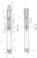
- the embodiment in Figure 1 comprises a first hollow container 10 that is capable of receiving and storing a solution in which a collected sample can be mixed, liquidized and/or homogenized.
- the first container has a first end 12 and a second end 13, which can both be closed by an end-wall integrally formed on the hollow container 10, or which can be formed by an openable wall, for example a wall that is screwed onto or into the first container 10, or fixed on the container like a plug by shape-fitting.
- the hollow first container 10 comprises a trough-hole 11.
- a transport-pin 14 that has preferably a shape that closely matches the shape of the through-hole 11.
- the transport-pin 14 comprises a recess 15 with a predetermined size.
- This recess 15 can be filled with a sample or a sample that is already diluted with a solution.
- the recess 15 can comprise a bottom wall and side walls, but can also be formed as a through-hole in the transport-pin 14.
- the transport-pin 14 can furthermore comprise a plurality of such recesses. In Figure 1a , the entire recess is outside of the first container 10.
- the recess 15 is only in part on the outer side of container 10, as long as the recess does not provide a connection between the inner side of the first container 10 and the outer side of the first container 10. I.e. as long as the recess 15 is at least in part on the outside of the container, no particles, no sample or anything else can infiltrate the container through the through-hole 11.
- the recess 15 is formed as a through-hole.
- the transport-pin 14 is moveable between an initial position (as show in Figure 1a ), which is the position with the recess at least partly outside the first container 10, and an end position (as shown in Figure lb), in which the recess 15 is positioned at least partially on the inner side of the first container 10.
- the transport-pin 14 can be press-fitted into the through-hole 11.
- the transport-pin 14 and/or through-hole 11 comprises at least one seal 17a, 17b for sealing the through-hole 11 when the transport-pin 14 is in its initial position and/or the end-position.
- the seal 17a, 17b can be disposed at the through-hole 11 and can be made of rubber, silicon, Teflon, ceramic, any kind of plastic or synthetic material or any other suitable material.
- the seal 17a, 17b can also be disposed at the transport-pin 14.
- the seal 17a is located at a position that will be in contact with the through-hole 11 in the end position 3 of the transport-pin 14, and the seal 17b is in a position which will be in contact with the through-hole 11, when the transport-pin 14 is in its initial position.
- the whole transport-pin 14 can be covered by a seal 17a, 17b as long as the recess 15 is not covered as well.
- the transport-pin 14 and the through-hole 11 can comprise both a seal.
- the seal 17a, 17b at the through-hole 11 and the seal at the transport-pin 14 may then be of different materials, so as to provide an easy movement of the transport-pin 14 within the through-hole 11.
- the material of the seal 17a, 17b at the transport-pin 14 in the region of the initial position and the end position can also be made of a different material than the rest of the seal on the transport-pin 14, e.g. with a very high friction in view of the through-hole 11, to stop the transport-pin 14 if it is in the initial position or the end position.
- the transport-pin 14 and/or the through-hole 11 can comprise at least one latch 16a, 16b that prohibits unforced movement of the transport-pin 14 in its initial position and/or the end position.
- the latch 16a, 16b can be formed into or onto the sealing 17a, 17b.
- the latch 16a, 16b is for example a protrusion in a radial direction of the tube 10 (in Figures 1a and 1b in a direction perpendicular to the center axis Z).
- the transport-pin 14 and/or the through-hole 11 can then comprise a corresponding recess, with which the protrusion will engage and latch.
- the latch can be made of any kind of silicon, Teflon, ceramic, any kind of plastic or synthetic material or any other suitable material, but preferably of a rubber or rubber-like material, to provide suitable sealing functions.
- the through-hole 11 is formed as a longitudinal cylinder-shaped hole, which is formed into an extension 20 that extends along the center axis Z in an axial direction.
- the hole can be formed in any kind of geometry.
- the transport-pin 14 can be guided in the through-hole 11 by guiding grooves and corresponding guiding protrusions on the transport-pin. These grooves and protrusions (not shown in the Figures) could be formed in an axial direction in the through-hole 11 and in the transport-pin 14. However, it does not make any difference if the grooves are formed in the through-hole 11 or the transport-pin 14.
- these features are enough to make the tube working for mixing, diluting and preserving a sample.
- the recess 15 in the transport-pin can be filled with a sample and the transport-pin 14 can then be pushed by, for example, a cap (not shown) with a bigger diameter than the hollow first container 10, into the first container 10. After that, the sample can be mixed and diluted in the solution and stored in the hollow first container 10.
- This embodiment would then serve as a tube with an integrated sample pin.
- the preferred embodiment as shown in Figure 1a and 1b includes a second container 30 for receiving and storing a solution.
- a solution can mean any liquid. However, it is possible to store a lyophilisate, a powder or other solid particles in one or both containers. To liquidize these particles, liquid like water has to be filled in the container storing the particles, before the sample will be diluted. This can be done for example by an extra valve, or, in case of the second container, through the opening for the sample pin. These liquidized particles are also meant by the term solution.
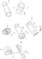
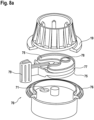
- the second container 30 comprises an outer tube 30a ( Figure 2f ), an inner tube 30b ( Figure 2e ) and a proximal tube or cap 30c ( Figure 2g ).
- these elements can be single parts, but they can also be formed integrally (in one piece).
- the first end of the container 10 is formed as a part of the inner tube 30b, as is the through-hole 11.
- the single elements of the assembly as shown in Figures 2a to 2g are just one particular possibility to construct the tube 1, and the different parts of the tube 1 can be formed integrally, can be divided into additional single parts or can be divided into different parts than shown in Figures 2a to 2g .
- the second container 30 is located with the distal end 31 on the first end 12 of the first container 10, such that the transport-pin 14 protrudes into the second container 30, and the second container 30 further comprises a proximal end 32 and an opening 34 suitable for inserting a sample pin 50.
- the proximal end 32 of the second container 30, in this case the proximal tube or cap 30c, comprises an accommodating part 38 that is suitable to receive a sample pin 50.
- This accommodating part 38 can be formed in a way to interact with a sample pin 50, which will be described later.
- a sediment portion 37 which is preferably formed tapered or in a conical shape. Between the wall of the tube 30b and this sediment portion 37, debris and particles of the sample can settle down after its homogenization.
- the sediment portion 37 can be replaced by a filter (not shown) such as a mesh or a fine net.
- fabric or other suitable tissue can be used as a filter that covers at least the recess of the transport-pin 14, but preferably the whole transport-pin 14 in the second container 30.
- the opening 34 of the second container 30 can be formed as a transversal septum 35 having an axial passageway 36 therethrough.
- a transversal septum 35 eases introducing a sample pin 50 into the second container 30 and comprises additional features such as stripping off excess sample material present on such a sample pin.
- the accommodating part 38 of the proximal tube 30c is formed such, that a sample pin 50 is movable into a first position (see Figure 1a ), in which the sample can be brought into contact with the solution contained in the second container 30, and to a second position, in which the sample pin 50 pushes the transport-pin 14 from the initial position into its end position (see Figure 1b ).
- the first position of the sample pin can thereby be indicated by, for example, a first rib which protrudes radially inwards in the accommodating part 38 of the proximal tube 30c (or single radial protrusions), and which are breakable to allow the sample pin to move further axially inwards in the second container 30.
- a guide groove 40 for guiding a movement of a sample pin 50.
- the guide groove 40 then can control the movement along the axis Z by interacting with a protrusion 58 of the sample pin 50.
- the guide groove 40 is formed by axially and circumferentially extending grooves 41, 42, 43. These grooves are shown in Figure 4 .
- the accommodating part 38 of the proximal tube or cap 30c can also be formed such, that a sample pin 50 is fixable in the first position and/or a second position such that the sample pin 50 is locked from rejection and/or further forward movement.
- this is carried out by the wall 44 of the circumferential guide groove 42 that blocks the protrusion from further axial movement in inserting direction.
- the sample pin can be rotated into a blocked position P1 ( Figure 4 ) after pushing it into the first position.
- the protrusion is moved in the guide groove 42 away from the axial extension 41 of the groove 40 (in Figure 4 clockwise when seen from a top view), so that the sample pin 50 cannot be pulled back because the protrusion is locked axially in position P1.
- a fixable first position could also be carried out by protrusions protruding radially inward in the accommodation chamber, and interacting with corresponding recesses or protrusions of the sample pin 50 like a clip.
- the sample pin 50 is the rotated such that the protrusion moves from position P1 along groove 42 in the opposite direction (in Figure 4 counter-clockwise) into position P2. Then the sample pin can be pushed into the second position until the protrusion 58 reaches position P3. A further axial movement in insertion direction is the blocked by the end wall 45 of groove 43.
- the sample pin 50 is blocked in the second position ( Fig. 1b ) from further movement in at least the inserting direction, when the transport-pin 14 is in the end position.
- This can be done either as mentioned above by the guide groove interacting with a protrusion 58 of the sample pin 50, or by protrusions protruding inwardly radially in the accommodating part 38.
- a simple stopper in the accommodating part 38 and/or the end 32 of the accommodating part 38 it is possible to form this accommodating part 38 on or in the proximal end of a first hollow container, as long as it is not wished to implement a transport pin. I.e.
- the accommodation part 38 is disposed on a first hollow container 10, which does not comprise a transport pin.
- the accommodation part 38 includes a first locking means 81, which is here formed as a groove 81 that interacts with a corresponding protrusion on a sample pin, which will be described later. This groove is preferably formed only on a circumferential portion of the accommodation part 38.
- a second locking means is provided further downstream relative to the inserting direction of the sample pin 50.
- This second locking means 82 can also be formed as a groove that interacts possibly also with the same corresponding element on the sample pin as the first locking means 81.
- the second locking groove is formed preferably around the complete circumference of the accommodation part 38. In this manner, the second locking means can prevent any further movement in axial direction of the sample pin once it is locked in the second locking means 82.
- the groove can also be a protrusion like a rib and interacts with a corresponding groove on a sample pin.
- the accommodation part 38 can also comprise a guide 85.
- this guide 85 is formed as a guide rail 87 which is preferably inclined and serves to guide a corresponding protrusion of a sample pin into a receiving slot 86.
- An accommodation part 38 can accommodate the handle of the sample pin within the accommodation part, but can also be inserted in the handle of the sample pin. In any case, it accommodates the elongated pin 52.
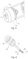
- the first container 10 has at its second end 13 a discharge port 18 where it is suitable for discharging a diluted sample. On the second end 13 is furthermore provided a first fitting element 19.
- the device 70 On the first container 10 is disposed a discharge device 70 for controlling discharge of the diluted sample via the discharge port 18.
- the device 70 has a discharge-opening 71, for discharging the diluted sample, and has a second fitting element 73, that cooperates with the first fitting element 19 to mount the discharge device 70 on the first container 10.
- At least a portion of the discharge device 70 is movable between two or more positions. These positions are preferably a discharge position, in which a diluted sample can be discharged, and a closed position in which the sample cannot be discharged.
- the discharge device can sealingly cover the discharge port 18 in the closed position; and in the discharge position the discharge-opening 71 is then moved to a position where the discharge-opening 71 is connected with the discharge port 18, but closed towards to the first container 10.
- a volume like a chamber or a small container is provided.
- This chamber or small container has a predetermined volume 78 and is preferably located in the discharge device 70.
- the discharge-opening 71' is relatively not moveable to the discharge port 18 of the hollow first container 10.
- Such a device is shown in Figures 5 , 8a and 8b . It is preferred that in the closed position the volume 78, e.g. the chamber or small container, is connected to the discharge port 18 and is filled with a solution. In this case the discharge port 18 is big enough to not affect the mixing of the sample in the solution, i.e. that a total exchange of solution between the volume and the container 10 is secured.
- the moveable portion 77 of the discharge device 70 is moved to the discharge position and the diluted sample is discharged out of the discharge opening 71'.
- the volume can also be initially in the discharge position, although it cannot initially contain sample liquid to be discharged.
- the moveable portion 77 of discharge device has first to be moved into the closed position to fill the volume 78 with a diluted sample.
- the volumetric discharge can be done as explained below, for example by a pressure in the hollow first container 10, by a pressure applied to the container 10 or by gravitational force preferably supported by a vent or valve (not shown) disposed somewhere at the first end 12 of the first container 10.
- the discharge device can also be moveable between three positions, an initial (closed) position, in which the volume is neither connected to the discharge port 18, nor to the discharge-opening 71', a second position, in which the volume is connected to the second container 10 via the discharge port 18 and is filled with the diluted sample, and an end (discharge) position, in which the sample can be discharged via the discharge-opening 71'.
- connection between the discharge device 70 and the hollow container 10 can be realized by fixing the discharging device 70 with a recess 73 complementary to the protruding pin 19.
- the protruding pin 19 is formed with a gap in the middle, to enable the functionality of a clip and engage with step-like portions in the corresponding recess 73.
- the discharge device 70 can be rotated between at least two positions.
- the discharge device 70 can also be fixed on the hollow first container 10 by a welding portion 76.
- a welding portion can for example be disposed on a part of the discharge device 70 that does not need to be relatively moveable in view of the first hollow container 10.
- a corresponding welding portion can be provided on the container as the fixing portion 19 and welded onto the welding portion 76 of the discharge device 70.
- this welding portion 76 is shown as a circumferential ring that protrudes outwardly. In this manner, it is easy to access for welding.
- the moveable portion 77 can be formed as a plate or cylinder including the above mentioned volume 78.
- a seal 75 can be provided on one or both sides of the moveable portion 77, e.g. a flat sheet made of rubber or silicone or any other suitable sealing material.
- the moveable portion 77 can comprise ribs on the outer surface to enhance the manual movement of the moveable portion 77.
- a protruding handle 79 or grip can be provided.
- the movement of the moveable portion 77 can be restricted by stopping means 90a, 90b on the fixed part of the discharge device 70 and/or on the first hollow container 10, in particular at the second end 13 thereof.
- stopping means 90a, 90b interact with corresponding abutment portions 92 on the moveable portion 77.
- this is carried out by the circumferential welding portion 19, 76 and the protruding handle 79.
- the handle 79 abuts with the abutment portions 92 against the stopping means 90a, 90b of the welding portion 19, 76 and is stopped from moving further.
- a cap (not shown) can be provided. This cap covers the discharge device. The cap also prevents movement of the discharge device, either by sufficiently covering the moveable portion 77 (in particular completely), or by blocking the handle 79.
- Blocking the handle 52 can for example be carried out by a protrusion that protrudes upwards from the cap into the movement path of the handle 79.
- a protrusion can either have a simple recess in which the handle is locked as long as the cap is on the tube, or can be combined with the stopper 90a, 90b if they are formed on the tube.
- Another possibility is to design the second end 13 with rails in which the discharge device 70 can slide. Then, the discharge device could be pushed, for example with a thumb of the user, from the closed position to an open position, in which the discharge port 18 is connected with the discharge-opening 71. In this way, it is possible to ensure that on the one hand discharging the diluted solution is not possible by accident, and, on the other hand, the discharge-opening 71 can be closed again.
- the discharge device can be connected with breakable connections with the second end 13 of the container 10 when it is in the initial, closed position.
- the discharge device 70 can include a sealing 75, preferably in form of a ring made of rubber, silicon, Teflon, ceramic, any kind of plastic or synthetic material or any other suitable material.
- This sealing 75 is disposed between the moveable portion of the discharge device 70 and the static part, which is either the second end 13 of the first container 10 or a static part of the discharge device 70 fixed at the second end 13 of the first container 10.
- the sealing 75 seals the cut between the moveable portion of the discharge device and the static part so that leaking of the diluted sample can be avoided, in particular with regard of a movement of the moveable portion of the discharge device 70.
- the volumetric discharge of the diluted solution can be carried out by pressure, which is increased in the hollow first container 10, for example due to the transport-pin 14 pushed into the first container 10.
- Another possibility is to define the geometry of the discharge port 18 and/or the discharge-opening 71 to allow a quantitative and predetermined volume transfer of the liquidized and diluted sample. That is, the opening has a size to enable that a drop with a predetermined size will drop off the opening. In particular, the liquid will be slowly come out of the discharge device 70 until the opening cannot hold the increasing drop at the discharge-opening 71 of the discharge device 70.
- the force to get the liquid out can be simple gravitational force supported by a vent or valve 74, can be the pressure inside the first hollow container 10 or can also be a pressure applied on the container, for which the container itself should be made of a flexible material.
- the diluted sample filled in the volume is discharged out of the discharge-opening 71' by gravitational force or by another device which pushes the diluted sample out of the chamber.
- the chamber could be designed of a flexible material in the way of a hose or a sleeve. This hose or sleeve can then be pressed together and the filling can be discharged via the discharge-opening 71, 71'.
- Another preferred embodiment comprises a vent or valve 74 in the discharge device 70 that connects the volume with the outside of the tube and enables the introduction of air into the volume.
- a valve 74 preferably a one-way-valve is chosen.
- a one-way-valve can also be disposed on the rotating part and be always in connection with the volume or chamber.
- the valve 74 restricts the leakage of the solution in the volume and is closed sealingly while the volume is filled with solution of the first container 10.
- the one-way-valve 74 allows air or a gas to enter the volume, when the solution has to be discharged from the chamber.
- a vent or valve can be activated manually.
- a tube 1 for mixing, diluting, preserving and discharging a sample comprises a hollow first container 10 comprising a solution and a discharge device 70 for discharging the solution and a hollow second container 30 also comprising a solution and an introduction port 34 for introducing a sample pin 50, wherein the first container 10 and the second container 30 are connected by a transfer device 14 that enables at least a sealed transfer of the solution from the second container 30 into the first container 10.
- a tube 1 provides a safe and hygienic transfer of the solution of one container to another.
- a tube is highly practical for home use by a patient, in particular if the diluted sample has to be further processed.
- first container 10 and second container 30 can be fixed together, preferably at their ends opposite to the discharge device 70 (which can be basically also a breakable discharge device of the prior art).
- the transfer device 14 can be a transport-pin 14 as described in this invention, but can also be for example a (preferably manually driven) sleeve pump (not shown) or hose pump (not shown) combined with one or two one-way-valves disposed at the pump device.
- the valve(s) enable(s) the solution to flow from the second container 30 to the first container 10, but restricts flowing in the opposite direction.
- a transfer device is a third tube (not shown) that is disposed between the second and the first containers and being adapted to be opened and closed to the second container 30 for being filled with the solution and for stopping the flow connection and being adapted to be opened and closed to the first container 10, to further dilute the sample of the second container 30 therein.
- a direct flow-connection between the second 30 and the first container 10 should be avoided.
- the third container should not be opened to the first and second containers simultaneously.
- the device comprises a sample pin 50.
- any prior art sample pin with an elongated pin 51 and a handle 52, located at a proximal end of the elongated pin 51 will work properly.
- a very suitable prior art design comprises one or more circumferential grooves at the elongated pin.
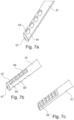
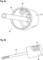
- a further design of a sample pin 50 for collecting a sample comprises an elongated pin 51 including a handle 52 located at a proximal end of the elongated pin 51 and at least one recess 54' with a predetermined volume preferably located at a distal portion of the elongated pin 51, wherein the recess 54' has the shape of a circumferential groove, that has an circumferential angle of maximum 180° degrees (this is shown in Figures 7b, 7c ).
- the circumferential angle can be measured along the edge 59, with respect to the center of the elongated pin 51 and/or with respect to the inside surfaces 53 of the side edges 55' of the recess 54'.
- a more liquid sample can be better kept in the recess.
- the circumferential angle is measured from the center of the preferably cylindrical elongated pin 51 or from the middle of the bottom plane with respect to the top of the cut-out sides of the recess 54'.
- the shape of the recess is highly practical for flushing out the sample contained in the recess 54'.
- the bottom of the recess 54' is completely flat (without the protruding middle as show in Figures 7a, 7b ) or has a deepened shape.
- An embodiment of another sample pin for collecting a sample comprises an elongated pin 51, a handle 52, located at a proximal end of the elongated pin 51 and at least one recess 54 with a predetermined volume that is preferably located at a distal portion of the elongated pin 51.
- This recess 54 is formed into the elongated pin, such that the elongated pin has essentially the same shape over its entire length.
- This recess 54 comprises only one opening with one edge, wherein the complete edge 55 of the opening is above the bottom of the recess 54 when seen in a side-view and the opening is facing upwards.
- the recess 54 is somehow spoon-like, to avoid that a very liquid sample can escape by dripping off the sample pin 50.
- the distal tip of the pin 51 comprises a tapered portion 57 or a rounded portion. This eases introducing the sample pin 50 into the tube 1, in particular into the transversal septum 35 of the second container 30, resp. the proximal part 30c thereof or, if the transport pin is not used, in the corresponding accommodation part including the transversal septum of the hollow first container. Furthermore the tapered or rounded portion 57 at the distal end of elongated pin 51 eases the introduction of the sample pin 50 into a very solid and/or hard sample.
- the handle 52 of the sample pin 50 comprises a protrusion 58, protruding outwards from the circumference of the handle 52. This protrusion is in particular useful in connection with the guiding groove 40, 41, 42, 43 of the second container 30.
- a sample pin can also comprise a handle 52 that has special features (see Figures 9a, 9b ).
- a handle 52 can be used with any prior art pin or pin 51 as described above.
- the handle 52 comprises a locking portion 83 corresponding to the locking portions 81, 82 that can be used in the accommodation part 38 of the hollow first container 10.
- there is only provided one single locking means 83 on the handle 52 but it is possible to provide more locking means, e.g. one for each locking means on the accommodation part 38. This might be the case, if the locking means have different diameters.
- the handle can comprise a gripping means 91, that serves to enable a proper manual hold of the sample pin and that can also be used as a pressing means to release the sample pin out of the first position of the first locking means.
- the sample pin can comprise a protrusion 58.
- this protrusion is protruding inwards, since in this embodiment the accommodation part 38 is inserted in the inner part of the handle 52.
- the protruding part extends axially along the handle and can have a tapered tip on the insertion side which eases sliding the sample pin 50 along a guide 85 of the tube.
- locking means and the guide can each be provided alone, it is equally possible to include these features simultaneously. They can provide a synergistic effect, as explained below.
- the handle In the first position, the handle is locked in the first locking means 81.
- the first locking means are adjusted to hold the sample pin in the first position, but it is possible to retract the sample pin or to push it further without destroying the tube or the sample pin and by using only a relatively small force. This can be done by providing a groove and a corresponding rib which are only slightly engaging each other. Another possibility is to provide the first locking means only on a circumferential portion.
- the handle can then be pressed on a pressing portion 91 and is thereby deformed to release the locking means 81 of the tube from the locking means 83 of the handle, e. g. the protruding rib from the corresponding groove. Such a deformation can be very small.
- the first position can therefore be used as a delivery position before use of the tube.
- the pin 51 seals the hollow container with the solution for diluting the sample and the handle is locked in the first locking means in the first position.
- the second position is for use after the sample has been collected.
- the sample pin is introduced back into the tube and pushed beyond the first position to the second locking means 82.
- These locking means are preferably very strong, so that the handle cannot be retracted once the second locking means is reached without using improper force or destroying the tube.
- the second locking means is therefore formed as a circumferential groove 82 (or rib) which interacts with the corresponding rib 83 (or groove) on the handle 52. Due to the circumferential shape, the pressing means cannot retract the rib out of the groove.
- the second position is therefore used to tightly and irreversibly close the tube. This is particularly useful to enhance the hygiene of the tube.
- the guide 85 can have mainly two functions. Firstly, it is used to support opening of the handle.
- the protrusion 58 is only partly (or not at all) in the receiving slot 86.
- the protrusion is pressed against the guide 85 and applies a force in opening direction on the handle. This is enhanced, if both of the guiding members, the guide 85 and the protrusion are formed inclined or tapered.
- the guide 85 and the protrusion 58 are guiding the sample pin then in a predetermined position, by sliding the protrusion 58 along the guide.
- the protrusion 58 is accommodated in the receiving slot 86. If so, rotation of the sample pin 50 is blocked by the side walls of the receiving slot 86 which abuts against the protrusion 58.
- the opening support of the guide cannot be used to open the tube once the sample pin is fixed in the second position.
- the sample pin 50 is introduced into a sample, which can be very liquid, soft, sticky or very hard. Due to the recesses 54, it will require a little bit more pressure to force a very solid sample into the recess 54, but once in the recess 54, the sample will not fall off. Additionally, a very liquid sample is easily collected due to these recesses 54 by capillary force and/or the spoon-like structure of the recesses 54. Then, the sample pin 50 is introduced into the second container 30, thereby removing all superfluous sample adhered on the elongated pin 51 by respectively in the transversal septum 35.
- the protrusion 58 is guided in the guide groove 40,41, 42, 43 and will be stopped in a first position
- the sample pin 50 is rotated into an intermediate, first locking-position (PI).
- the recesses 54 are now in the second container 30 and the sample in the recesses 54 can be diluted in the solution in the second container 30. This can be done by shaking the tube or by using a mixing device (e.g. a vortexer).
- the sample pin 50 is then rotated in the opposite direction following the guide groove 40, 41, 42, 43 and pressed into the accommodation part 38 of the second container 30, and will be stopped in a second locking position (P3). Thereby, the tapered end 57 of the sample pin 50 presses the transport-pin 14 into the first container 10.
- the transport-pin 14 comprises in the recess 15 a predetermined amount of diluted sample of the second container 30 and transports it into the first hollow container 10. This predetermined amount transferred into the hollow container 10 is then mixed with the solution contained in the first container 10. After that, the diluted sample in the first container 10 can be discharged as described above.
Landscapes
- Health & Medical Sciences (AREA)
- Life Sciences & Earth Sciences (AREA)
- General Health & Medical Sciences (AREA)
- Chemical & Material Sciences (AREA)
- Pathology (AREA)
- Analytical Chemistry (AREA)
- Heart & Thoracic Surgery (AREA)
- Surgery (AREA)
- Veterinary Medicine (AREA)
- Public Health (AREA)
- Engineering & Computer Science (AREA)
- Biomedical Technology (AREA)
- Animal Behavior & Ethology (AREA)
- Medical Informatics (AREA)
- Molecular Biology (AREA)
- General Physics & Mathematics (AREA)
- Physics & Mathematics (AREA)
- Biochemistry (AREA)
- Immunology (AREA)
- Hematology (AREA)
- Clinical Laboratory Science (AREA)
- Chemical Kinetics & Catalysis (AREA)
- Sampling And Sample Adjustment (AREA)
- Investigating Or Analysing Biological Materials (AREA)
- Apparatus Associated With Microorganisms And Enzymes (AREA)
Claims (10)
- Röhrchen (1) zum Mischen, Verdünnen, Konservieren und Auslassen einer Probe, in Kombination mit einer Probe, das Röhrchen weist einen hohlen ersten Behälter (10) zum Aufnehmen und/oder Aufbewahren einer Lösung auf, wobei der hohle erste Behälter (10) erste und zweite Enden (12, 13) aufweist, wobei das erste Ende (12) ein erstes Durchgangsloch (11) aufweist, das zum Einsetzen eines Probenstifts (50) mit einer zu dem Durchgangsloch passenden Form (11) geeignet ist, und das zweite Ende (13) eine Ausgabeöffnung (18) aufweist, die zum Ausgeben einer verdünnten Probe geeignet ist, wobei der hohle erste Behälter (10) erste Verriegelungsmittel (81) zum Verriegeln des Probenstiftes (50) in einer ersten Position aufweist und dadurch gekennzeichnet, dass der hohle erste Behälter (1) weiterhin zweite Verriegelungsmittel (82) zum Verriegeln des Probenstiftes (50) in einer zweiten Position und zum Verhindern des Zurückziehens des Probenstiftes aufweist, weiter umfassend einen Probenstift, wobei der Probenstift (50) mit einem länglichen Stift (51), einem Griff (52), der an einem proximalen Ende des länglichen Stiftes (51) angeordnet ist, und mindestens einer Vertiefung (54) mit einem vorbestimmten Volumen aufweist, die in einem distalen Abschnitt des länglichen Stifts (51) ausgebildet ist, wobei der Griff (52) mindestens einen Verriegelungsabschnitt (83) aufweist, der den ersten und/oder zweiten Verriegelungsmitteln (81, 82) entspricht.
- Röhrchen (1) nach Anspruch 1, wobei sich das zweite Verriegelungsmittel in Einführrichtung weiter stromabwärts als die erste Verriegelungsposition befinden.
- Röhrchen (1) nach einem der Ansprüche 1 oder 2, wobei das erste Verriegelungsmittel (81) eine Rippe oder eine Nut umfasst, die an einem Umfangsabschnitt des ersten Endes (12) des hohlen ersten Behälters (10) angeordnet ist.
- Röhrchen (1) nach einem der Ansprüche 1 bis 3, wobei das zweite Verriegelungsmittel (82) eine Rippe oder eine Nut umfasst, die auf dem Umfang des ersten Endes (12) des hohlen ersten Behälters (10) angeordnet ist.
- Röhrchen nach einem der Ansprüche 1 bis 4, wobei der Probenstift (50) Drückabschnitte (91) aufweist, die dazu dienen, den Griff (52) zu verformen, um den Probenstift (50) von dem ersten Verriegelungsmittel (81) zu entriegeln.
- Röhrchen (1) nach einem oder mehreren der vorhergehenden Ansprüche, wobei der hohle erste Behälter (10) weiter eine Führung (85) umfasst, die an dem ersten Ende (12) des ersten hohlen Behälters (10) angeordnet ist, die mit dem Probenstift (50) zusammenwirkt, um den Probenstift in einer vorbestimmten Position zu führen.
- Röhrchen (1) nach Anspruch 6, wobei die Führung (85) geneigte Abschnitte (87) aufweist.
- Röhrchen (1) nach Anspruch 6 oder 7, wobei die Führung (85) einen Aufnahmeschlitz (86) aufweist, der dazu dient, eine vorbestimmte Position für einen Probenstift festzulegen.
- Röhrchen (1) nach einem der Ansprüche 6 bis 8, ferner umfassend einen Probenstift (50) zum Sammeln einer Probe, wobei der Probenstift einen länglichen Stift (51), einen Griff (52), der an einem proximalen Ende des länglichen Stiftes (51) angeordnet ist, und mindestens eine Aussparung (54) mit einem vorbestimmten Volumen umfasst, die in einem distalen Abschnitt des länglichen Stifts (51) ausgebildet ist, wobei der Griff (52) ferner einen Vorsprung (58) umfasst, der mit der entsprechenden Führung (85) zusammenwirkt.
- Röhrchen nach Anspruch 9, wobei der Vorsprung (58) des Griffs (52) am Ende in Einführrichtung verjüngt ist.
Priority Applications (2)
| Application Number | Priority Date | Filing Date | Title |
|---|---|---|---|
| EP13701953.5A EP2833795B2 (de) | 2012-01-20 | 2013-01-18 | Probenentnahme-, verdünnungs- und ausgabevorrichtung |
| PL13701953.5T PL2833795T5 (pl) | 2012-01-20 | 2013-01-18 | Urządzenie do ekstrakcji, rozcieńczania i opróżniania próbek |
Applications Claiming Priority (3)
| Application Number | Priority Date | Filing Date | Title |
|---|---|---|---|
| EP12151959.9A EP2617362B1 (de) | 2012-01-20 | 2012-01-20 | Probenentnahme-, Verdünnungs- und Ausgabevorrichtung |
| EP13701953.5A EP2833795B2 (de) | 2012-01-20 | 2013-01-18 | Probenentnahme-, verdünnungs- und ausgabevorrichtung |
| PCT/EP2013/050988 WO2013107893A1 (en) | 2012-01-20 | 2013-01-18 | Sample extracting, diluting and discharging device |
Publications (3)
| Publication Number | Publication Date |
|---|---|
| EP2833795A1 EP2833795A1 (de) | 2015-02-11 |
| EP2833795B1 EP2833795B1 (de) | 2018-05-16 |
| EP2833795B2 true EP2833795B2 (de) | 2023-04-19 |
Family
ID=47630275
Family Applications (2)
| Application Number | Title | Priority Date | Filing Date |
|---|---|---|---|
| EP12151959.9A Active EP2617362B1 (de) | 2012-01-20 | 2012-01-20 | Probenentnahme-, Verdünnungs- und Ausgabevorrichtung |
| EP13701953.5A Active EP2833795B2 (de) | 2012-01-20 | 2013-01-18 | Probenentnahme-, verdünnungs- und ausgabevorrichtung |
Family Applications Before (1)
| Application Number | Title | Priority Date | Filing Date |
|---|---|---|---|
| EP12151959.9A Active EP2617362B1 (de) | 2012-01-20 | 2012-01-20 | Probenentnahme-, Verdünnungs- und Ausgabevorrichtung |
Country Status (13)
| Country | Link |
|---|---|
| US (2) | US9752967B2 (de) |
| EP (2) | EP2617362B1 (de) |
| JP (2) | JP6043365B2 (de) |
| KR (2) | KR101875862B1 (de) |
| CN (1) | CN104135945B (de) |
| AU (2) | AU2013210989B2 (de) |
| BR (1) | BR112014017755B1 (de) |
| CA (2) | CA2861386C (de) |
| DK (2) | DK2617362T3 (de) |
| ES (2) | ES2734448T3 (de) |
| FI (1) | FI2833795T4 (de) |
| PL (1) | PL2833795T5 (de) |
| WO (1) | WO2013107893A1 (de) |
Families Citing this family (25)
| Publication number | Priority date | Publication date | Assignee | Title |
|---|---|---|---|---|
| US4923936A (en) | 1989-02-21 | 1990-05-08 | The Bfgoodrich Company | Heteropolymetallate metathesis catalysts for cycloolefin polymerization |
| US20150122713A1 (en) * | 2013-11-07 | 2015-05-07 | Yung Kang Medical Device & Technologic Co., Ltd. | Prp obtaining device |
| CN104849100B (zh) * | 2015-05-22 | 2017-10-27 | 浙江硕华医用塑料有限公司 | 一种唾液样品的收集保存器 |
| CN105372440B (zh) * | 2015-12-08 | 2017-10-13 | 郑磊 | 一种多腔室粪便取样容器及分析方法 |
| CN105388151B (zh) * | 2015-12-08 | 2018-01-02 | 王东升 | 一种全自动粪便分析系统及分析方法 |
| DE102016004686A1 (de) | 2016-04-19 | 2017-10-19 | KME Kern Medical Engineering GmbH | Stuhlprobenaufnahmeset |
| CN106198103B (zh) * | 2016-07-06 | 2019-08-23 | 张明亮 | 一种液体定量采集器 |
| IT201700001864A1 (it) * | 2017-01-10 | 2018-07-10 | Traces S R L | Contenitore per la raccolta e la conservazione di campioni bioptici. |
| USD829340S1 (en) * | 2017-05-15 | 2018-09-25 | Charles River Laboratories, Inc. | Depressor |
| USD821605S1 (en) * | 2017-05-15 | 2018-06-26 | Charles River Laboratories, Inc. | Scanning device adapter |
| WO2019072356A1 (de) | 2017-10-13 | 2019-04-18 | KME Kern Medical Engineering GmbH | Stuhlprobenaufnahmeset |
| KR102105233B1 (ko) * | 2017-12-06 | 2020-06-05 | 권택민 | 점성이 있는 소량 샘플의 교반에 적합한 실험실용 믹서 |
| ES2904674T3 (es) * | 2018-02-26 | 2022-04-05 | Becton Dickinson Co | Dispositivo de recogida de fluidos biológicos y módulo de recogida |
| US11293839B2 (en) | 2018-08-16 | 2022-04-05 | Epitope Biotechnology Co., Ltd. | Device for fecal sample collection and extraction |
| CN111044723A (zh) * | 2018-10-12 | 2020-04-21 | 谢鲍生物科技股份公司 | 含有胰弹性蛋白酶-1-特异性的抗体以及样品准备装置的新型测试试剂盒 |
| CN109490005A (zh) * | 2018-11-30 | 2019-03-19 | 北京君立康博科技有限公司 | 粪便定量取样装置 |
| GB2582156B (en) * | 2019-03-12 | 2022-09-28 | Quantumdx Group Ltd | Specimen container for specimen pre-processing |
| CN110057652B (zh) * | 2019-04-25 | 2024-01-12 | 壹妙芯(厦门)科技有限公司 | 一种生物样品采集装置 |
| DE102019006582A1 (de) * | 2019-09-19 | 2021-03-25 | Schebo Biotech Ag | Neuer Testkit, enthaltend Tumor-M2-PK-spezifische Antikörper sowie eine Probenvorbereitungsvorrichtung |
| CN113267365B (zh) * | 2021-06-25 | 2024-05-14 | 上海领鲜科技有限公司 | 用于大便检测的大便稀释混合采样机构及其控制方法 |
| CN114272968A (zh) * | 2021-12-10 | 2022-04-05 | 武汉佰起科技有限公司 | 一种液体检测样储存管 |
| WO2025113829A1 (en) | 2023-11-28 | 2025-06-05 | Immundiagnostik Ag | Stool sampling device for processing in autosampler systems |
| WO2025172196A1 (en) | 2024-02-12 | 2025-08-21 | Immundiagnostik Ag | Stool collection and extraction system for analysis of faecal specimens on infectious diseases |
| WO2025233937A1 (en) * | 2024-05-07 | 2025-11-13 | Harp Diagnostics Ltd. | Automatic system for preparing and analyzing a biologic sample and method thereof |
| CN119935644B (zh) * | 2025-04-07 | 2025-07-01 | 山西省检验检测中心(山西省标准计量技术研究院) | 一种土地质量调查的底泥采样装置 |
Citations (3)
| Publication number | Priority date | Publication date | Assignee | Title |
|---|---|---|---|---|
| EP0638803A1 (de) † | 1992-12-18 | 1995-02-15 | Eiken Kagaku Kabushiki Kaisha | Aufname-und transportbehälter für fäzes |
| EP1986006A1 (de) † | 2005-12-16 | 2008-10-29 | Nipro Corporation | Auffangbehälter für faeces |
| WO2009136445A1 (ja) † | 2008-05-09 | 2009-11-12 | Dicプラスチック株式会社 | 採便容器 |
Family Cites Families (29)
| Publication number | Priority date | Publication date | Assignee | Title |
|---|---|---|---|---|
| US3200984A (en) | 1962-08-14 | 1965-08-17 | Mueller Brass Co | Pressure seal plug |
| JPS4716455Y1 (de) * | 1970-07-10 | 1972-06-09 | ||
| JPS52527Y2 (de) | 1971-03-25 | 1977-01-08 | ||
| US3695475A (en) | 1971-06-15 | 1972-10-03 | Continental Can Co | Child-proof closure |
| JPH05256746A (ja) * | 1991-05-07 | 1993-10-05 | Toshiki Mano | 採尿器 |
| JPH0716455A (ja) | 1993-06-30 | 1995-01-20 | Showa Kagaku Kogyo Kk | ケイソウ土濾過助剤・充填剤の流動層焼成による製造方法 |
| JP3399645B2 (ja) * | 1993-07-29 | 2003-04-21 | 大日本印刷株式会社 | 便内潜血検出装置 |
| JP3790009B2 (ja) * | 1997-04-21 | 2006-06-28 | ディックプラスチック株式会社 | 採便用容器 |
| JP3622827B2 (ja) * | 1998-05-06 | 2005-02-23 | ニプロ株式会社 | 便採取容器 |
| US6299842B1 (en) | 1999-03-05 | 2001-10-09 | Meridian Bioscience, Inc. | Biological sampling and storage container utilizing a desiccant |
| JP2000338102A (ja) * | 1999-05-26 | 2000-12-08 | Eiken Kizai Kk | 採便容器 |
| JP3336302B2 (ja) * | 1999-09-30 | 2002-10-21 | 株式会社町田予防衛生研究所 | 採便容器 |
| WO2002055994A1 (fr) | 2001-01-16 | 2002-07-18 | International Reagents Corporation | Dispositif et procede d'echantillonnage de matieres fecales |
| JP2003043030A (ja) * | 2001-08-03 | 2003-02-13 | Tfb Inc | 試料採取用器具 |
| US7879293B2 (en) * | 2001-09-28 | 2011-02-01 | Orasure Technologies, Inc. | Sample collector and test device |
| ITMI20020287U1 (it) * | 2002-05-31 | 2003-12-01 | Sentinel Ch S R L | Tubo di estrazione per la raccolta di campioni di feci |
| ITVI20020131A1 (it) | 2002-06-17 | 2003-12-17 | Vacutest Kima Srl | Tappo con protezione per provette |
| US6921370B2 (en) | 2002-07-25 | 2005-07-26 | Alfa Scientific Designs, Inc. | Specimen collection and storage and transport device and method |
| JP4319590B2 (ja) * | 2004-07-12 | 2009-08-26 | アルフレッサファーマ株式会社 | 採便容器 |
| DE102004043883B4 (de) * | 2004-09-10 | 2007-04-19 | Bartec Gmbh | Probenflaschen und Verfahren zur Probenahme |
| US20060210448A1 (en) | 2005-03-10 | 2006-09-21 | Naishu Wang | Fecal specimen collection, preserving and transport device and method |
| US20070140915A1 (en) * | 2005-12-12 | 2007-06-21 | Cytyc Corporation | Method and Apparatus for Obtaining Aliquot from Liquid-Based Cytological Sample |
| US7686771B2 (en) * | 2005-12-12 | 2010-03-30 | Cytyc Corporation | Method and apparatus for obtaining aliquot from liquid-based cytological sample |
| US7878900B2 (en) | 2005-12-14 | 2011-02-01 | Multimedia Games, Inc. | Electronic sweepstakes system providing multiple game presentations for revealing results from a single sweepstakes game |
| US7871568B2 (en) | 2006-01-23 | 2011-01-18 | Quidel Corporation | Rapid test apparatus |
| JP4933301B2 (ja) * | 2007-02-22 | 2012-05-16 | キヤノン株式会社 | 検体処理装置 |
| CN201096654Y (zh) * | 2007-06-28 | 2008-08-06 | 万华普曼生物工程有限公司 | 一种新型采便器 |
| DE102007057760B3 (de) | 2007-11-30 | 2009-02-05 | DIMA Gesellschaft für Diagnostika mbH | Vorrichtung zum Entnehmen und Lösen einer pastösen Probe |
| TW200946072A (en) * | 2008-05-09 | 2009-11-16 | Dic Plastics Inc | Device for sampling feces |
-
2012
- 2012-01-20 ES ES12151959T patent/ES2734448T3/es active Active
- 2012-01-20 EP EP12151959.9A patent/EP2617362B1/de active Active
- 2012-01-20 DK DK12151959.9T patent/DK2617362T3/da active
-
2013
- 2013-01-18 ES ES13701953T patent/ES2683373T5/es active Active
- 2013-01-18 DK DK13701953.5T patent/DK2833795T4/da active
- 2013-01-18 KR KR1020177005665A patent/KR101875862B1/ko active Active
- 2013-01-18 CN CN201380009198.3A patent/CN104135945B/zh active Active
- 2013-01-18 US US14/373,290 patent/US9752967B2/en active Active
- 2013-01-18 JP JP2014552646A patent/JP6043365B2/ja active Active
- 2013-01-18 AU AU2013210989A patent/AU2013210989B2/en active Active
- 2013-01-18 PL PL13701953.5T patent/PL2833795T5/pl unknown
- 2013-01-18 EP EP13701953.5A patent/EP2833795B2/de active Active
- 2013-01-18 FI FIEP13701953.5T patent/FI2833795T4/fi active
- 2013-01-18 CA CA2861386A patent/CA2861386C/en active Active
- 2013-01-18 KR KR1020147022607A patent/KR101716740B1/ko active Active
- 2013-01-18 BR BR112014017755-4A patent/BR112014017755B1/pt active IP Right Grant
- 2013-01-18 WO PCT/EP2013/050988 patent/WO2013107893A1/en not_active Ceased
- 2013-01-18 CA CA2997598A patent/CA2997598C/en active Active
-
2016
- 2016-05-13 AU AU2016203121A patent/AU2016203121C1/en active Active
- 2016-09-20 JP JP2016182929A patent/JP6307132B2/ja active Active
-
2017
- 2017-07-21 US US15/656,336 patent/US20180010989A1/en not_active Abandoned
Patent Citations (3)
| Publication number | Priority date | Publication date | Assignee | Title |
|---|---|---|---|---|
| EP0638803A1 (de) † | 1992-12-18 | 1995-02-15 | Eiken Kagaku Kabushiki Kaisha | Aufname-und transportbehälter für fäzes |
| EP1986006A1 (de) † | 2005-12-16 | 2008-10-29 | Nipro Corporation | Auffangbehälter für faeces |
| WO2009136445A1 (ja) † | 2008-05-09 | 2009-11-12 | Dicプラスチック株式会社 | 採便容器 |
Also Published As
Similar Documents
| Publication | Publication Date | Title |
|---|---|---|
| EP2833795B2 (de) | Probenentnahme-, verdünnungs- und ausgabevorrichtung | |
| US20250275759A1 (en) | Sample collection devices | |
| AU2021204781B2 (en) | Biological fluid collection and stabilization system |
Legal Events
| Date | Code | Title | Description |
|---|---|---|---|
| PUAI | Public reference made under article 153(3) epc to a published international application that has entered the european phase |
Free format text: ORIGINAL CODE: 0009012 |
|
| 17P | Request for examination filed |
Effective date: 20141009 |
|
| AK | Designated contracting states |
Kind code of ref document: A1 Designated state(s): AL AT BE BG CH CY CZ DE DK EE ES FI FR GB GR HR HU IE IS IT LI LT LU LV MC MK MT NL NO PL PT RO RS SE SI SK SM TR |
|
| AX | Request for extension of the european patent |
Extension state: BA ME |
|
| DAX | Request for extension of the european patent (deleted) | ||
| RIN1 | Information on inventor provided before grant (corrected) |
Inventor name: ROSETH, ARNE Inventor name: JERMANN, THOMAS Inventor name: WEBER, JAKOB Inventor name: PAVELS PETERSEN, ERIK |
|
| REG | Reference to a national code |
Ref country code: DE Ref legal event code: R079 Ref document number: 602013037476 Country of ref document: DE Free format text: PREVIOUS MAIN CLASS: A61B0010000000 Ipc: G01N0001380000 |
|
| GRAP | Despatch of communication of intention to grant a patent |
Free format text: ORIGINAL CODE: EPIDOSNIGR1 |
|
| STAA | Information on the status of an ep patent application or granted ep patent |
Free format text: STATUS: GRANT OF PATENT IS INTENDED |
|
| RIC1 | Information provided on ipc code assigned before grant |
Ipc: G01N 1/38 20060101AFI20171110BHEP Ipc: B01L 3/00 20060101ALI20171110BHEP Ipc: A61B 10/00 20060101ALI20171110BHEP |
|
| INTG | Intention to grant announced |
Effective date: 20171207 |
|
| RIN1 | Information on inventor provided before grant (corrected) |
Inventor name: PAVELS PETERSEN, ERIK Inventor name: JERMANN, THOMAS Inventor name: WEBER, JAKOB Inventor name: ROSETH, ARNE |
|
| GRAS | Grant fee paid |
Free format text: ORIGINAL CODE: EPIDOSNIGR3 |
|
| GRAA | (expected) grant |
Free format text: ORIGINAL CODE: 0009210 |
|
| STAA | Information on the status of an ep patent application or granted ep patent |
Free format text: STATUS: THE PATENT HAS BEEN GRANTED |
|
| AK | Designated contracting states |
Kind code of ref document: B1 Designated state(s): AL AT BE BG CH CY CZ DE DK EE ES FI FR GB GR HR HU IE IS IT LI LT LU LV MC MK MT NL NO PL PT RO RS SE SI SK SM TR |
|
| REG | Reference to a national code |
Ref country code: GB Ref legal event code: FG4D |
|
| REG | Reference to a national code |
Ref country code: CH Ref legal event code: EP |
|
| REG | Reference to a national code |
Ref country code: IE Ref legal event code: FG4D |
|
| REG | Reference to a national code |
Ref country code: DE Ref legal event code: R096 Ref document number: 602013037476 Country of ref document: DE |
|
| REG | Reference to a national code |
Ref country code: AT Ref legal event code: REF Ref document number: 1000014 Country of ref document: AT Kind code of ref document: T Effective date: 20180615 |
|
| REG | Reference to a national code |
Ref country code: CH Ref legal event code: NV Representative=s name: STOLMAR AND PARTNER INTELLECTUAL PROPERTY S.A., CH |
|
| REG | Reference to a national code |
Ref country code: DK Ref legal event code: T3 Effective date: 20180809 |
|
| REG | Reference to a national code |
Ref country code: NL Ref legal event code: FP |
|
| REG | Reference to a national code |
Ref country code: SE Ref legal event code: TRGR |
|
| REG | Reference to a national code |
Ref country code: ES Ref legal event code: FG2A Ref document number: 2683373 Country of ref document: ES Kind code of ref document: T3 Effective date: 20180926 |
|
| REG | Reference to a national code |
Ref country code: LT Ref legal event code: MG4D |
|
| REG | Reference to a national code |
Ref country code: NO Ref legal event code: T2 Effective date: 20180516 |
|
| PG25 | Lapsed in a contracting state [announced via postgrant information from national office to epo] |
Ref country code: BG Free format text: LAPSE BECAUSE OF FAILURE TO SUBMIT A TRANSLATION OF THE DESCRIPTION OR TO PAY THE FEE WITHIN THE PRESCRIBED TIME-LIMIT Effective date: 20180816 Ref country code: LT Free format text: LAPSE BECAUSE OF FAILURE TO SUBMIT A TRANSLATION OF THE DESCRIPTION OR TO PAY THE FEE WITHIN THE PRESCRIBED TIME-LIMIT Effective date: 20180516 |
|
| PG25 | Lapsed in a contracting state [announced via postgrant information from national office to epo] |
Ref country code: LV Free format text: LAPSE BECAUSE OF FAILURE TO SUBMIT A TRANSLATION OF THE DESCRIPTION OR TO PAY THE FEE WITHIN THE PRESCRIBED TIME-LIMIT Effective date: 20180516 Ref country code: HR Free format text: LAPSE BECAUSE OF FAILURE TO SUBMIT A TRANSLATION OF THE DESCRIPTION OR TO PAY THE FEE WITHIN THE PRESCRIBED TIME-LIMIT Effective date: 20180516 Ref country code: GR Free format text: LAPSE BECAUSE OF FAILURE TO SUBMIT A TRANSLATION OF THE DESCRIPTION OR TO PAY THE FEE WITHIN THE PRESCRIBED TIME-LIMIT Effective date: 20180817 Ref country code: RS Free format text: LAPSE BECAUSE OF FAILURE TO SUBMIT A TRANSLATION OF THE DESCRIPTION OR TO PAY THE FEE WITHIN THE PRESCRIBED TIME-LIMIT Effective date: 20180516 |
|
| REG | Reference to a national code |
Ref country code: AT Ref legal event code: MK05 Ref document number: 1000014 Country of ref document: AT Kind code of ref document: T Effective date: 20180516 |
|
| PG25 | Lapsed in a contracting state [announced via postgrant information from national office to epo] |
Ref country code: EE Free format text: LAPSE BECAUSE OF FAILURE TO SUBMIT A TRANSLATION OF THE DESCRIPTION OR TO PAY THE FEE WITHIN THE PRESCRIBED TIME-LIMIT Effective date: 20180516 Ref country code: RO Free format text: LAPSE BECAUSE OF FAILURE TO SUBMIT A TRANSLATION OF THE DESCRIPTION OR TO PAY THE FEE WITHIN THE PRESCRIBED TIME-LIMIT Effective date: 20180516 Ref country code: AT Free format text: LAPSE BECAUSE OF FAILURE TO SUBMIT A TRANSLATION OF THE DESCRIPTION OR TO PAY THE FEE WITHIN THE PRESCRIBED TIME-LIMIT Effective date: 20180516 Ref country code: SK Free format text: LAPSE BECAUSE OF FAILURE TO SUBMIT A TRANSLATION OF THE DESCRIPTION OR TO PAY THE FEE WITHIN THE PRESCRIBED TIME-LIMIT Effective date: 20180516 |
|
| REG | Reference to a national code |
Ref country code: DE Ref legal event code: R026 Ref document number: 602013037476 Country of ref document: DE |
|
| PLBI | Opposition filed |
Free format text: ORIGINAL CODE: 0009260 |
|
| PLAX | Notice of opposition and request to file observation + time limit sent |
Free format text: ORIGINAL CODE: EPIDOSNOBS2 |
|
| PG25 | Lapsed in a contracting state [announced via postgrant information from national office to epo] |
Ref country code: SM Free format text: LAPSE BECAUSE OF FAILURE TO SUBMIT A TRANSLATION OF THE DESCRIPTION OR TO PAY THE FEE WITHIN THE PRESCRIBED TIME-LIMIT Effective date: 20180516 |
|
| 26 | Opposition filed |
Opponent name: IMMUNDIAGNOSTIK AG Effective date: 20190204 |
|
| PG25 | Lapsed in a contracting state [announced via postgrant information from national office to epo] |
Ref country code: SI Free format text: LAPSE BECAUSE OF FAILURE TO SUBMIT A TRANSLATION OF THE DESCRIPTION OR TO PAY THE FEE WITHIN THE PRESCRIBED TIME-LIMIT Effective date: 20180516 |
|
| PLBB | Reply of patent proprietor to notice(s) of opposition received |
Free format text: ORIGINAL CODE: EPIDOSNOBS3 |
|
| PG25 | Lapsed in a contracting state [announced via postgrant information from national office to epo] |
Ref country code: MC Free format text: LAPSE BECAUSE OF FAILURE TO SUBMIT A TRANSLATION OF THE DESCRIPTION OR TO PAY THE FEE WITHIN THE PRESCRIBED TIME-LIMIT Effective date: 20180516 |
|
| PG25 | Lapsed in a contracting state [announced via postgrant information from national office to epo] |
Ref country code: LU Free format text: LAPSE BECAUSE OF NON-PAYMENT OF DUE FEES Effective date: 20190118 |
|
| REG | Reference to a national code |
Ref country code: IE Ref legal event code: MM4A |
|
| PG25 | Lapsed in a contracting state [announced via postgrant information from national office to epo] |
Ref country code: AL Free format text: LAPSE BECAUSE OF FAILURE TO SUBMIT A TRANSLATION OF THE DESCRIPTION OR TO PAY THE FEE WITHIN THE PRESCRIBED TIME-LIMIT Effective date: 20180516 |
|
| PG25 | Lapsed in a contracting state [announced via postgrant information from national office to epo] |
Ref country code: IE Free format text: LAPSE BECAUSE OF NON-PAYMENT OF DUE FEES Effective date: 20190118 |
|
| PG25 | Lapsed in a contracting state [announced via postgrant information from national office to epo] |
Ref country code: TR Free format text: LAPSE BECAUSE OF FAILURE TO SUBMIT A TRANSLATION OF THE DESCRIPTION OR TO PAY THE FEE WITHIN THE PRESCRIBED TIME-LIMIT Effective date: 20180516 |
|
| PG25 | Lapsed in a contracting state [announced via postgrant information from national office to epo] |
Ref country code: PT Free format text: LAPSE BECAUSE OF FAILURE TO SUBMIT A TRANSLATION OF THE DESCRIPTION OR TO PAY THE FEE WITHIN THE PRESCRIBED TIME-LIMIT Effective date: 20180917 Ref country code: MT Free format text: LAPSE BECAUSE OF NON-PAYMENT OF DUE FEES Effective date: 20190118 |
|
| PG25 | Lapsed in a contracting state [announced via postgrant information from national office to epo] |
Ref country code: CY Free format text: LAPSE BECAUSE OF FAILURE TO SUBMIT A TRANSLATION OF THE DESCRIPTION OR TO PAY THE FEE WITHIN THE PRESCRIBED TIME-LIMIT Effective date: 20180516 |
|
| PG25 | Lapsed in a contracting state [announced via postgrant information from national office to epo] |
Ref country code: IS Free format text: LAPSE BECAUSE OF FAILURE TO SUBMIT A TRANSLATION OF THE DESCRIPTION OR TO PAY THE FEE WITHIN THE PRESCRIBED TIME-LIMIT Effective date: 20180916 |
|
| PG25 | Lapsed in a contracting state [announced via postgrant information from national office to epo] |
Ref country code: HU Free format text: LAPSE BECAUSE OF FAILURE TO SUBMIT A TRANSLATION OF THE DESCRIPTION OR TO PAY THE FEE WITHIN THE PRESCRIBED TIME-LIMIT; INVALID AB INITIO Effective date: 20130118 |
|
| PG25 | Lapsed in a contracting state [announced via postgrant information from national office to epo] |
Ref country code: MK Free format text: LAPSE BECAUSE OF FAILURE TO SUBMIT A TRANSLATION OF THE DESCRIPTION OR TO PAY THE FEE WITHIN THE PRESCRIBED TIME-LIMIT Effective date: 20180516 |
|
| REG | Reference to a national code |
Ref country code: FR Ref legal event code: PLFP Year of fee payment: 11 |
|
| PUAH | Patent maintained in amended form |
Free format text: ORIGINAL CODE: 0009272 |
|
| STAA | Information on the status of an ep patent application or granted ep patent |
Free format text: STATUS: PATENT MAINTAINED AS AMENDED |
|
| 27A | Patent maintained in amended form |
Effective date: 20230419 |
|
| AK | Designated contracting states |
Kind code of ref document: B2 Designated state(s): AL AT BE BG CH CY CZ DE DK EE ES FI FR GB GR HR HU IE IS IT LI LT LU LV MC MK MT NL NO PL PT RO RS SE SI SK SM TR |
|
| REG | Reference to a national code |
Ref country code: DE Ref legal event code: R102 Ref document number: 602013037476 Country of ref document: DE |
|
| REG | Reference to a national code |
Ref country code: NO Ref legal event code: T2 Effective date: 20180516 |
|
| REG | Reference to a national code |
Ref country code: DK Ref legal event code: T4 Effective date: 20230719 |
|
| REG | Reference to a national code |
Ref country code: NL Ref legal event code: FP |
|
| REG | Reference to a national code |
Ref country code: SE Ref legal event code: RPEO |
|
| REG | Reference to a national code |
Ref country code: ES Ref legal event code: DC2A Ref document number: 2683373 Country of ref document: ES Kind code of ref document: T5 Effective date: 20231005 |
|
| PGFP | Annual fee paid to national office [announced via postgrant information from national office to epo] |
Ref country code: NL Payment date: 20250121 Year of fee payment: 13 |
|
| PGFP | Annual fee paid to national office [announced via postgrant information from national office to epo] |
Ref country code: DE Payment date: 20250130 Year of fee payment: 13 |
|
| PGFP | Annual fee paid to national office [announced via postgrant information from national office to epo] |
Ref country code: DK Payment date: 20250124 Year of fee payment: 13 Ref country code: FI Payment date: 20250124 Year of fee payment: 13 |
|
| PGFP | Annual fee paid to national office [announced via postgrant information from national office to epo] |
Ref country code: ES Payment date: 20250226 Year of fee payment: 13 |
|
| PGFP | Annual fee paid to national office [announced via postgrant information from national office to epo] |
Ref country code: SE Payment date: 20250121 Year of fee payment: 13 |
|
| PGFP | Annual fee paid to national office [announced via postgrant information from national office to epo] |
Ref country code: NO Payment date: 20250124 Year of fee payment: 13 |
|
| PGFP | Annual fee paid to national office [announced via postgrant information from national office to epo] |
Ref country code: BE Payment date: 20250121 Year of fee payment: 13 Ref country code: CH Payment date: 20250201 Year of fee payment: 13 |
|
| PGFP | Annual fee paid to national office [announced via postgrant information from national office to epo] |
Ref country code: CZ Payment date: 20250110 Year of fee payment: 13 Ref country code: FR Payment date: 20250127 Year of fee payment: 13 |
|
| PGFP | Annual fee paid to national office [announced via postgrant information from national office to epo] |
Ref country code: IT Payment date: 20250129 Year of fee payment: 13 Ref country code: GB Payment date: 20250128 Year of fee payment: 13 |
|
| PGFP | Annual fee paid to national office [announced via postgrant information from national office to epo] |
Ref country code: PL Payment date: 20251223 Year of fee payment: 14 |
|
| REG | Reference to a national code |
Ref country code: CH Ref legal event code: U11 Free format text: ST27 STATUS EVENT CODE: U-0-0-U10-U11 (AS PROVIDED BY THE NATIONAL OFFICE) Effective date: 20260201 |