EP2833458B1 - Laminierungsvorrichtung und laminierungsverfahren - Google Patents
Laminierungsvorrichtung und laminierungsverfahren Download PDFInfo
- Publication number
- EP2833458B1 EP2833458B1 EP13770202.3A EP13770202A EP2833458B1 EP 2833458 B1 EP2833458 B1 EP 2833458B1 EP 13770202 A EP13770202 A EP 13770202A EP 2833458 B1 EP2833458 B1 EP 2833458B1
- Authority
- EP
- European Patent Office
- Prior art keywords
- unit
- electrode sheet
- suction
- separator
- arrived
- Prior art date
- Legal status (The legal status is an assumption and is not a legal conclusion. Google has not performed a legal analysis and makes no representation as to the accuracy of the status listed.)
- Not-in-force
Links
- 238000000034 method Methods 0.000 title claims description 22
- 238000003475 lamination Methods 0.000 title 2
- 238000007599 discharging Methods 0.000 claims description 9
- 230000006870 function Effects 0.000 description 24
- 238000004519 manufacturing process Methods 0.000 description 23
- 239000011888 foil Substances 0.000 description 12
- WHXSMMKQMYFTQS-UHFFFAOYSA-N Lithium Chemical compound [Li] WHXSMMKQMYFTQS-UHFFFAOYSA-N 0.000 description 4
- 229910052744 lithium Inorganic materials 0.000 description 4
- 229910001416 lithium ion Inorganic materials 0.000 description 4
- -1 polyethylene Polymers 0.000 description 4
- 239000004698 Polyethylene Substances 0.000 description 3
- 239000004743 Polypropylene Substances 0.000 description 3
- 238000010276 construction Methods 0.000 description 3
- 229920000573 polyethylene Polymers 0.000 description 3
- 229920000098 polyolefin Polymers 0.000 description 3
- 229920001155 polypropylene Polymers 0.000 description 3
- 238000005520 cutting process Methods 0.000 description 2
- 238000010586 diagram Methods 0.000 description 2
- 238000001035 drying Methods 0.000 description 2
- 239000000428 dust Substances 0.000 description 2
- 239000003792 electrolyte Substances 0.000 description 2
- 239000000446 fuel Substances 0.000 description 2
- 239000000463 material Substances 0.000 description 2
- 229910052751 metal Inorganic materials 0.000 description 2
- 239000002184 metal Substances 0.000 description 2
- 238000004806 packaging method and process Methods 0.000 description 2
- 230000035699 permeability Effects 0.000 description 2
- 238000005096 rolling process Methods 0.000 description 2
- RYGMFSIKBFXOCR-UHFFFAOYSA-N Copper Chemical compound [Cu] RYGMFSIKBFXOCR-UHFFFAOYSA-N 0.000 description 1
- PXHVJJICTQNCMI-UHFFFAOYSA-N Nickel Chemical compound [Ni] PXHVJJICTQNCMI-UHFFFAOYSA-N 0.000 description 1
- 229910052782 aluminium Inorganic materials 0.000 description 1
- XAGFODPZIPBFFR-UHFFFAOYSA-N aluminium Chemical compound [Al] XAGFODPZIPBFFR-UHFFFAOYSA-N 0.000 description 1
- 239000011248 coating agent Substances 0.000 description 1
- 238000000576 coating method Methods 0.000 description 1
- 239000011889 copper foil Substances 0.000 description 1
- 230000002349 favourable effect Effects 0.000 description 1
- 238000010030 laminating Methods 0.000 description 1
- 239000007773 negative electrode material Substances 0.000 description 1
- 239000004745 nonwoven fabric Substances 0.000 description 1
- 230000003287 optical effect Effects 0.000 description 1
- 239000011148 porous material Substances 0.000 description 1
- 239000007774 positive electrode material Substances 0.000 description 1
- 239000000843 powder Substances 0.000 description 1
Images


Classifications
-
- H—ELECTRICITY
- H01—ELECTRIC ELEMENTS
- H01M—PROCESSES OR MEANS, e.g. BATTERIES, FOR THE DIRECT CONVERSION OF CHEMICAL ENERGY INTO ELECTRICAL ENERGY
- H01M10/00—Secondary cells; Manufacture thereof
- H01M10/04—Construction or manufacture in general
- H01M10/0404—Machines for assembling batteries
-
- H—ELECTRICITY
- H01—ELECTRIC ELEMENTS
- H01M—PROCESSES OR MEANS, e.g. BATTERIES, FOR THE DIRECT CONVERSION OF CHEMICAL ENERGY INTO ELECTRICAL ENERGY
- H01M10/00—Secondary cells; Manufacture thereof
- H01M10/05—Accumulators with non-aqueous electrolyte
- H01M10/058—Construction or manufacture
-
- H—ELECTRICITY
- H01—ELECTRIC ELEMENTS
- H01M—PROCESSES OR MEANS, e.g. BATTERIES, FOR THE DIRECT CONVERSION OF CHEMICAL ENERGY INTO ELECTRICAL ENERGY
- H01M6/00—Primary cells; Manufacture thereof
- H01M6/005—Devices for making primary cells
-
- H—ELECTRICITY
- H01—ELECTRIC ELEMENTS
- H01M—PROCESSES OR MEANS, e.g. BATTERIES, FOR THE DIRECT CONVERSION OF CHEMICAL ENERGY INTO ELECTRICAL ENERGY
- H01M8/00—Fuel cells; Manufacture thereof
- H01M8/24—Grouping of fuel cells, e.g. stacking of fuel cells
- H01M8/2404—Processes or apparatus for grouping fuel cells
-
- H—ELECTRICITY
- H01—ELECTRIC ELEMENTS
- H01M—PROCESSES OR MEANS, e.g. BATTERIES, FOR THE DIRECT CONVERSION OF CHEMICAL ENERGY INTO ELECTRICAL ENERGY
- H01M10/00—Secondary cells; Manufacture thereof
- H01M10/05—Accumulators with non-aqueous electrolyte
- H01M10/052—Li-accumulators
- H01M10/0525—Rocking-chair batteries, i.e. batteries with lithium insertion or intercalation in both electrodes; Lithium-ion batteries
-
- H—ELECTRICITY
- H01—ELECTRIC ELEMENTS
- H01M—PROCESSES OR MEANS, e.g. BATTERIES, FOR THE DIRECT CONVERSION OF CHEMICAL ENERGY INTO ELECTRICAL ENERGY
- H01M10/00—Secondary cells; Manufacture thereof
- H01M10/05—Accumulators with non-aqueous electrolyte
- H01M10/058—Construction or manufacture
- H01M10/0585—Construction or manufacture of accumulators having only flat construction elements, i.e. flat positive electrodes, flat negative electrodes and flat separators
-
- Y—GENERAL TAGGING OF NEW TECHNOLOGICAL DEVELOPMENTS; GENERAL TAGGING OF CROSS-SECTIONAL TECHNOLOGIES SPANNING OVER SEVERAL SECTIONS OF THE IPC; TECHNICAL SUBJECTS COVERED BY FORMER USPC CROSS-REFERENCE ART COLLECTIONS [XRACs] AND DIGESTS
- Y02—TECHNOLOGIES OR APPLICATIONS FOR MITIGATION OR ADAPTATION AGAINST CLIMATE CHANGE
- Y02E—REDUCTION OF GREENHOUSE GAS [GHG] EMISSIONS, RELATED TO ENERGY GENERATION, TRANSMISSION OR DISTRIBUTION
- Y02E60/00—Enabling technologies; Technologies with a potential or indirect contribution to GHG emissions mitigation
- Y02E60/10—Energy storage using batteries
-
- Y—GENERAL TAGGING OF NEW TECHNOLOGICAL DEVELOPMENTS; GENERAL TAGGING OF CROSS-SECTIONAL TECHNOLOGIES SPANNING OVER SEVERAL SECTIONS OF THE IPC; TECHNICAL SUBJECTS COVERED BY FORMER USPC CROSS-REFERENCE ART COLLECTIONS [XRACs] AND DIGESTS
- Y02—TECHNOLOGIES OR APPLICATIONS FOR MITIGATION OR ADAPTATION AGAINST CLIMATE CHANGE
- Y02E—REDUCTION OF GREENHOUSE GAS [GHG] EMISSIONS, RELATED TO ENERGY GENERATION, TRANSMISSION OR DISTRIBUTION
- Y02E60/00—Enabling technologies; Technologies with a potential or indirect contribution to GHG emissions mitigation
- Y02E60/30—Hydrogen technology
- Y02E60/50—Fuel cells
-
- Y—GENERAL TAGGING OF NEW TECHNOLOGICAL DEVELOPMENTS; GENERAL TAGGING OF CROSS-SECTIONAL TECHNOLOGIES SPANNING OVER SEVERAL SECTIONS OF THE IPC; TECHNICAL SUBJECTS COVERED BY FORMER USPC CROSS-REFERENCE ART COLLECTIONS [XRACs] AND DIGESTS
- Y02—TECHNOLOGIES OR APPLICATIONS FOR MITIGATION OR ADAPTATION AGAINST CLIMATE CHANGE
- Y02P—CLIMATE CHANGE MITIGATION TECHNOLOGIES IN THE PRODUCTION OR PROCESSING OF GOODS
- Y02P70/00—Climate change mitigation technologies in the production process for final industrial or consumer products
- Y02P70/50—Manufacturing or production processes characterised by the final manufactured product
-
- Y—GENERAL TAGGING OF NEW TECHNOLOGICAL DEVELOPMENTS; GENERAL TAGGING OF CROSS-SECTIONAL TECHNOLOGIES SPANNING OVER SEVERAL SECTIONS OF THE IPC; TECHNICAL SUBJECTS COVERED BY FORMER USPC CROSS-REFERENCE ART COLLECTIONS [XRACs] AND DIGESTS
- Y10—TECHNICAL SUBJECTS COVERED BY FORMER USPC
- Y10T—TECHNICAL SUBJECTS COVERED BY FORMER US CLASSIFICATION
- Y10T29/00—Metal working
- Y10T29/49—Method of mechanical manufacture
- Y10T29/49002—Electrical device making
- Y10T29/49108—Electric battery cell making
-
- Y—GENERAL TAGGING OF NEW TECHNOLOGICAL DEVELOPMENTS; GENERAL TAGGING OF CROSS-SECTIONAL TECHNOLOGIES SPANNING OVER SEVERAL SECTIONS OF THE IPC; TECHNICAL SUBJECTS COVERED BY FORMER USPC CROSS-REFERENCE ART COLLECTIONS [XRACs] AND DIGESTS
- Y10—TECHNICAL SUBJECTS COVERED BY FORMER USPC
- Y10T—TECHNICAL SUBJECTS COVERED BY FORMER US CLASSIFICATION
- Y10T29/00—Metal working
- Y10T29/53—Means to assemble or disassemble
- Y10T29/5313—Means to assemble electrical device
- Y10T29/53135—Storage cell or battery
Definitions
- the present invention relates to an apparatus that manufactures a layered stack including a positive electrode sheet, a negative electrode sheet, and a separator, and to a method that uses such apparatus.
- Japanese Laid-Open Patent Publication No. 2008-282756 discloses the provision of a method of manufacturing and a manufacturing apparatus for a layered stack of a stacked (laminated) cell which have a high manufacturing yield and high manufacturing efficiency by substantially preventing the mixing in of dust and coating powder.
- the manufacturing apparatus for a layered stack cell in Document 1 is constructed so that vacuum chucking pads, which are a suction apparatus, do not vacuum chuck a negative electrode foil and a positive electrode foil directly and instead definitely chuck and convey such foils with a separator in between.
- the number of driving apparatuses required to move the vacuum chucking pads between the respective stages which are a separator supplying stage, a negative electrode foil supplying stage, a positive electrode foil supplying stage, and a stacking stage, is reduced, the number of locations where dust protection measures are necessary is also reduced, and if possible such measures are implemented at only one location.
- the movement path of the vacuum chucking pads in such case will be circumferential, arc-shaped, or linear, and each stage will be disposed along such movement path.
- the electrode structure (layered stack) used in a lithium cell or the like is manufactured by stacking or laminating a plurality of positive electrode plates (positive electrode sheets, positive electrode foils) and negative electrode plates (negative electrode sheets, negative electrode foils) with separators in between. For this reason, there is demand for an apparatus capable of precisely stacking positive electrode plates, negative electrode plates, and separators while separately picking up a separator, a positive electrode sheet, and a negative electrode sheet.
- the negative electrode foils and positive electrode foils are not directly vacuum chucked and are instead vacuum chucked via separators. This means that it is not possible to manufacture an electrode structure using separators with low air permeability.
- a first aspect of the present invention is a stacking apparatus including: a pickup unit including a plurality of suction units that pass a first position, a second position, a third position, and a fourth position, which are disposed at equal intervals in a first direction around a circumference, in order; a first supplying unit that supplies a first electrode sheet to the first position; a second supplying unit that supplies a sheet-like separator to the second position; a third supplying unit that supplies a second electrode sheet to the third position; a discharging unit that discharges, from the fourth position, a layered stack in which the first electrode sheet and the second electrode sheet have been alternately stacked (laminated) with the separator in between; and a driving unit that moves the respective suction units of the plurality of suction units in order to the first position, the second position, the third position, and the fourth position and also causes up-down movement of the respective suction units.
- the driving unit drives the suction units to perform moving up and down that includes following operations.
- a first operation moves the suction units that have arrived at the first position, the second position, and the third position up and down to respectively pick up a first electrode sheet, a separator, and a second electrode sheet and moves the suction unit that has arrived at the fourth position up and down to stack a separator.
- a second operation moves the suction unit that has arrived at the fourth position up and down to stack a second electrode sheet.
- a third operation moves the suction unit that has arrived at the second position up and down to pick up a separator and moves the suction unit that has arrived at the fourth position up and down to stack a separator.
- a fourth operation moves the suction unit that has arrived at the fourth position up and down to stack a first electrode sheet.
- a separator, a first electrode sheet, and a second electrode sheet are conveyed by different suction units and a second electrode sheet, a separator, a first electrode sheet, and another separator are stacked in that order at the fourth position. Accordingly, it is possible to manufacture a layered stack using a separator with low air permeability.
- the pickup unit only needs to rotate in the first direction and does not need to reverse the direction.
- the first operation and the third operation by picking up a separator at the second position in addition to stacking a separator at the fourth position, it is possible to continuously repeat an operation of stacking the first electrode sheets and the second electrode sheets with separators in between. This means that it is possible to manufacture a layered stack at comparatively high speed using a stacking apparatus with a simple construction.
- first position, the second position, the third position, and the fourth position are disposed at a pitch of 90° and for the pickup unit to include the suction units in four directions. It is also possible to dispose the first position, the second position, the third position, and the fourth position at a pitch of 45° or narrower.
- Another aspect of the present invention is a method including stacking first electrode sheets and second electrode sheets with sheet-like separators in between using a stacking apparatus.
- Such method may be a control method of a stacking apparatus, may be a method of manufacturing a layered stack, that is, an electrode assembly, or may be a method of manufacturing a cell including an electrode assembly, for example a secondary cell such as a lithium cell, or a cell, such as a fuel cell.
- the stacking apparatus includes: a plurality of suction units that pass a first position where a first electrode sheet is supplied, a second position where a sheet-like separator is supplied, a third position where a second electrode sheet is supplied, and a fourth position where the first electrode sheet and the second electrode sheet are laminated with a separator in between, in order, the first to fourth positions being a plurality of positions that are disposed at equal intervals in a first direction around a circumference.
- Stacking in such method includes the following steps.
- the driving unit includes: a first driving unit that rotationally drives the pickup unit; a second driving unit that moves the pickup unit up and down; and a third driving unit that moves the respective suction units up and down. It is also desirable for the stacking apparatus to further include a control unit that causes the third operation unit to move the respective suction units up and down in the first operation, the second operation, the third operation, and the fourth operation in synchronization with causing the second operation unit to move the pickup unit up and down.
- first to fourth steps described above in the method respectively include moving simultaneously up and down the plurality of suction units via a pickup unit and moving separately up and down the suction units that are picking up or stacking in synchronization with such simultaneous up and down movement.
- the stacking apparatus may include a first rotating stage that supplies a first electrode sheet to the first position, a second rotating stage that supplies a separator to the second position, a third rotating stage that supplies a second electrode sheet to the third position, and a fourth rotating stage that discharges a layered stack from the fourth position.
- a first rotating stage that supplies a first electrode sheet to the first position
- a second rotating stage that supplies a separator to the second position
- a third rotating stage that supplies a second electrode sheet to the third position
- a fourth rotating stage that discharges a layered stack from the fourth position.
- the method according to the present invention includes a control method of a stacking apparatus.
- This control method can be provided as a computer including computer resources, such as a CPU and memory, or as a program (program product) that causes a computer to operate and has been recorded on an appropriate medium (a CD-ROM or the like).
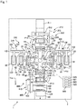
- FIG. 1 shows, by way of a plan view, an arrangement of one example of a stacking apparatus that manufactures an electrode structure (layered stack) for use in a lithium ion cell.
- the stacking apparatus 1 laminates positive electrode sheets 61, negative electrode sheets 62, and sheet-like separators 65 to manufacture a layered stack (laminated structure, electrode assembly, cell) 60.
- the stacking apparatus 1 includes a chassis 2 and a pickup unit (handler, index handler) 50 disposed in substantially the center of the chassis 2.
- the pickup unit 50 includes suction units (vacuum chucking heads, suction pads) HA, HB, HC, and HD disposed in four directions at a 90° pitch, with such suction units HA to HD respectively picking up one of a positive electrode sheet 61, a separator 65, and a negative electrode sheet 62 with predetermined timing while passing a first position P1, a second position P2, a third position P3, and a fourth position P4 in that order.
- the first position P1, the second position P2, the third position P3, and the fourth position P4 are disposed at equal intervals, which is a 90° pitch in the present embodiment, along a virtual circumference C1 shown by a dot-dash line, and the pickup unit 50 rotates so that the plurality of suction units (vacuum chucking units) HA to HD pass the first to fourth positions P1 to P4 in order in the counter-clockwise direction.
- the stacking apparatus 1 further includes a first supplying unit 100 that supplies a first electrode sheet 61 (positive electrode sheet, positive electrode plate) to the first position P1 of the chassis 2, a second supplying unit 200 that supplies a sheet-like separator 65 (separator) to the second position P2, a third supplying unit 300 that supplies a second electrode sheet 62 (negative electrode sheet, negative electrode plate) to the third position P3, and a discharging unit 400 that takes out a layered stack 60, in which positive electrode sheets 61, separators 65, and negative electrode sheets 62 have been stacked, from the fourth position P4.
- the first supplying unit 100, the second supplying unit 200, the third supplying unit 300, and the discharging unit 400 are disposed at a pitch of 90° in order in the counter-clockwise direction.
- the first supplying unit 100 includes a first rotating stage 10 and a positive electrode sheet supplying unit 110 that supplies a positive electrode sheet 61 to the first rotating stage 10.
- the first rotating stage 10 rotates in units of 180° (with a pitch of 180°) so as to move between a receiving position P11 and the first position P1.
- the first rotating stage 10 conveys the positive electrode sheet 61 supplied to the receiving position P11 from the positive electrode sheet supplying unit 110 to the first position P1.
- the first rotating stage 10 includes two pallets 13 disposed at positions with rotational symmetry of order 2 (positions at 180°), a driving unit 12 that rotates the first rotating stage 10 in the counter-clockwise direction, a camera 14 that confirms the posture (orientation) of the positive electrode sheet 61 supplied to the pallet 13 at the receiving position P11, and an XY ⁇ table 15 that moves the pallet 13 so as to adjust the alignment of the positive electrode sheet 61 at the first position P1.
- the direction of rotation of the first rotating stage 10 may be the clockwise direction. This also applies to the respective rotating stages described below.
- the positive electrode sheet supplying unit 110 includes a feeder 105 that removes one positive electrode sheet 61 at a time from a cartridge 120 in which a plurality of positive electrode sheets 61 are stored and supplies the positive electrode sheet 61 to the pallet 13 at the receiving position P11.
- a feeder 105 includes an arm 102 that vacuum chucks and conveys a positive electrode sheet 61 and an actuator 103 that drives the arm 102.
- the second supplying unit 200 includes a second rotating stage 20 and a separator supplying unit 210 that supplies a separator 65 to the second rotating stage 20.
- the second rotating stage 20 rotates in units of 180° to convey a separator 65 supplied to a receiving position P12 from the separator supplying unit 210 to the second position P2.
- the second rotating stage 20 includes two pallets 23 disposed at positions with rotational symmetry of order 2 (positions at 180°) and a driving apparatus 22 that rotates the second rotating stage 20 in the counter-clockwise direction.
- the separator supplying unit 210 includes a roll-like separator 211, a cutter 212 that pulls out a predetermined length of the separator from the roll-like separator 211 and cuts the separator into sheets of a predetermined size, and a feeder 205 that supplies the cut separators 65 one at a time to the pallet 23 at the receiving position P12.
- One example of the feeder 205 includes an arm 202 that vacuum chucks and conveys a separator 65 and an actuator 203 that drives the arm 202.
- the third supplying unit 300 includes a third rotating stage 30 and a negative electrode sheet supplying unit 310 that supplies a negative electrode sheet 62 to the third rotating stage 30.
- the third rotating stage 30 rotates by 180° to convey the negative electrode sheet 62 supplied to a receiving position P13 from a negative electrode sheet supplying unit 310 to the third position P3.
- the constructions of the third rotating stage 30 and the negative electrode sheet supplying unit 310 are respectively the same as the first rotating stage 10 and the positive electrode sheet supplying unit 110, aside from the object to be conveyed being the negative electrode sheets 62 from a cartridge 320 that stores a plurality of the negative electrode sheets 62. For this reason, the same numerals have been assigned and description of the constructions is omitted.
- the discharging unit 400 includes a fourth rotating stage 40 and an unloader unit 410 that bundles the layered stack 60 from the fourth rotating stage 40 and stores the layered stacks 60 in a stocker.
- the fourth rotating stage 40 rotates by 180° to convey the layered stack 60 laminated at the fourth position P4 to the unloading position P14.
- the fourth rotating stage 40 includes two pallets 43 disposed at positions with rotational symmetry of order 2 (positions at 180°), a driving apparatus 42 that rotationally drives the fourth rotating stage 40, a clamp (stopper) 45 that temporarily holds the layered stack 60 (the positive electrode sheet 61, the negative electrode sheet 62, and the separator 65) stacked on the respective pallets 43, and a cylinder 46 that lifts up the layered stack 60 at the unloading position P14 and hands over the layered stack 60 to the unloader unit 410.
- the clamp 45 includes hooks that press the four corners of the layered stack 60 or positions near the four corners from above.
- the unloader unit 410 includes a unit 420 that packages the unloaded layered stack 60 and a feeder 405 that conveys the layered stack 60 from the unloading position P14 to the packaging unit 420.
- the feeder 405 includes an arm 402 that supports the layered stack 60 lifted by the cylinder 46 from below and conveys the layered stack 60 and an actuator 403 that drives the arm 402.
- the packaging unit 420 packages the layered stack 60 by wrapping an appropriate material, for example, the same material as the separator, around the layered stack 60 that is a laminated structure and stores the layered stack 60 in a vessel, such as a cartridge, used for conveying.
- the pickup unit 50 that supports the suction heads HA to HD includes four arms 51a, 51b, 51c, and 51 d that extend in four directions at a pitch of 90°.
- the suction heads HA, HB, HC, and HD are attached to the respective front end portions of the arms 51 a to 51d and rotate in the counter-clockwise direction together with the pickup unit 50 (that is, the arms 51a to 51d).
- the suction heads HA, HB, HC, and HD are vacuum chucking heads that constructed so that the interiors of the heads are placed under negative pressure by a vacuum pump, not shown, and are capable of holding sheet-like members using suction and releasing (discharging) the sheet-like members that were held using suction (held by vacuum chucking) by placing the interiors of the heads at atmospheric pressure or by increasing the pressure.
- the stacking apparatus 1 further includes a driving unit 57 that rotates the suction heads HA, HB, HC, and HD in the counter-clockwise direction and also moves the heads up and down.
- the driving unit 57 includes a first driving unit 55 that rotationally drives the pickup unit 50 in which the arms 51a to 51d are integrated in the counter-clockwise direction, a second driving unit 56 that drives the pickup unit 50 as a whole up and down by a height W1, and separate cylinders (third driving units) 52a, 52b, 52c, and 52d that support the respective suction heads HA, HB, HC, and HD so that the heads move up and down by a height W2 with respect to the respective arms 51a to 51d.
- One example of the first driving unit 55 is an actuator for rotational driving, such as a motor.
- One example of the second driving unit 56 is an actuator for linear driving, such as an air cylinder.
- the stacking apparatus 1 further includes a control unit 500 that controls the respective suction heads HA to HD of the pickup unit 50, the separate cylinders 52a to 52d, the unit driving apparatus 55, the unit cylinder 56, and the like.
- the control unit 500 includes a first function (functional unit) 501 that rotates the pickup unit 50 in the counter-clockwise direction using the first driving unit 55 and temporarily stops the respective suction heads HA to HD at the respective positions of the first position P1 to the fourth position P4, a second function (functional unit) 502 that moves the pickup unit 50 up and down using the second driving unit 56, a third function (functional unit) 503 that moves the respective suction units HA to HD independently up and down using the separate cylinders 52a to 52d, and an operation control unit 505 that repeatedly carries out the operations described below with the functions above using the driving unit 57.
- a first function (functional unit) 501 that rotates the pickup unit 50 in the counter-clockwise direction using the first driving unit 55 and temporarily stops the respective suction heads HA to HD at the respective positions of the first position P1 to the fourth position P4
- a second function (functional unit) 502 that moves the pickup unit 50 up and down using the second driving unit 56
- a third function (functional unit) 503 that moves
- First operation suction units that have arrived at the first position P1, the second position P2, and the third position P3, for example, the suction units HA to HC, are moved up and down to respectively pick up a positive electrode sheet 61, a separator 65, and a negative electrode sheet 62 and the suction unit HD that has arrived at the fourth position P4 is moved up and down to stack a separator 65.
- Second operation the suction unit HC that has arrived at the fourth position P4 is moved up and down so as to stack the negative electrode sheet 62.
- the second function 502 controls the second driving unit 56 so that the suction heads HA to HD are placed at the lowest level when the suction heads HA to HD have arrived at one of the first position P1 to the fourth position P4.
- the second function 502 may move the pickup unit 50 up and down even while the pickup unit 50 is being rotated by the first driving unit 55 or may move the pickup unit 50 up and down when the pickup unit 50 has temporarily stopped at the respective positions.
- the third function 503 separately moves the suction heads HA to HD that pick up, or stack when at the fourth position P4, up and down in the respective operations described above.
- the third function 503 may separately move the suction heads HA to HD up and down even while the pickup unit 50 is being rotated by the first driving unit 55 or may separately move the suction heads HA to HD up and down when the pickup unit 50 has temporarily stopped at the respective positions.
- the third function 503 can reduce the time needed to move the suction heads HA to HD up and down.
- the positive electrode sheets 61 is a positive electrode sheet (positive electrode plate, positive electrode layer) 61 that constructs a layered stack 60 used for a lithium ion cell, and is produced by applying a positive electrode active material to both surfaces of metal foil, such as aluminum foil, drying, rolling, and then cutting to an appropriate size.
- a positive electrode active material such as aluminum foil, drying, rolling, and then cutting to an appropriate size.
- the negative electrode sheets 62 is a negative electrode sheet produced by applying a negative electrode active material to both surfaces of metal foil, such as nickel foil or copper foil, drying, rolling, and then cutting to an appropriate size.
- the positive electrode sheet 61 or the negative electrode sheet 62 are not limited to use in a lithium cell, and may be another type of cell or an electrode structure for a fuel cell.
- the separators 65 is a separator that prevents short circuits between the positive electrode sheet 61 and the negative electrode sheet 62 described above and may have a function for holding an electrolyte.
- the separator 65 is a microporous film composed of polyolefin such as polyethylene (PE) and polypropylene (PP), and also has a function whereby when an overcurrent flows, the pores in the film close up due to the resultant heat and thereby shut off the current.
- PE polyethylene
- PP polypropylene
- the separator 65 is not limited to only a single film of polyolefin or the like, and it is possible to use a three-layer structure where a polypropylene layer is sandwiched by polyethylene layers or a structure where polyolefin microporous film, organic nonwoven fabric, and the like are laminated.
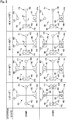
- FIG. 2 shows in further detail the operation of the stacking apparatus 1 when manufacturing the layered stack 60 at the fourth position P4 while rotating the pickup unit 50 in the counter-clockwise direction.
- FIG. 2 will be used to describe the procedure where the layered stack 60 is manufactured by the stacking apparatus 1 while referring to the angle ⁇ in the counter-clockwise direction between the first position P1 and the suction head HA.
- the "COME" row at the top in FIG. 2 shows a state when the respective suction heads HA to HD arrive, and the "DOWN" row at the bottom in FIG. 2 shows an operation carried out by the respective suction heads HA to HD after arriving.
- the suction head HA arrives at the second position P2 from the first position P1 (state S2, "COME" of the second operation).
- the angle ⁇ becomes 90°.
- the suction head HC that has arrived at the fourth position P4 is lowered by the separate cylinder 52c ("DOWN" of the second operation).
- the negative electrode sheet (second electrode sheet) 62 that was vacuum chucked by the suction head HC is released and is stacked on the separator 65.
- FIG. 3 shows how the pickup unit 50 is moved up and down (raised and lowered).
- FIG. 3(a) and (b) separately show how the pickup unit 50 carries out the second operation.
- the arms 51a and 51c of the pickup unit 50 rotate in the raised state. Focusing on the suction head HC, a distance W0 is maintained from the layered stack 60 that has been laminated at the fourth position P4, thereby making it possible to prevent interference with the layered stack 60.
- FIG. 3(b) shows a state where the suction heads HA and HC have been lowered.
- the suction heads HA and HC are lowered by the distance W1 together with the pickup unit 50 by the second driving unit 56.
- the suction head HC is lowered by a further distance W2 by the separate cylinder 52c.
- the suction head HC is lowered by the distance W0 that is the sum of the distance W1 and the distance W2.
- the third function 503 may include a function that controls the raising/lowering distance W2 of the separate cylinders 52a to 52d according to the thickness of the layered stack 60 stacked at the fourth position P4. It is possible, in a state where the raising/lowering distance W1 of the second driving unit 56 is kept constant, to control the distance by which the respective suction heads HA to HD are lowered in accordance with the height of the layered stack 60 stacked (manufactured) at the fourth position P4.
- the third function 503 may be equipped with a function that separately controls or adjusts the raising/lowering distance W2 of the separate cylinders 52a to 52d at the other positions P1 to P3 so that the respective suction heads HA to HD reach the pallets 13 or 23.
- a raising/lowering apparatus may be attached to the pallet 43 of the fourth position P4 and the height relative to the top of the layered stack 60 may be controlled on the pallet 43 side. It is possible to keep the raising/lowering distance W2 of the separate cylinders 52a to 52d constant.
- the suction head HA arrives at the third position P3 from the second position P2 (the state S3, "COME" of the third operation).
- the angle ⁇ that the suction head HA has moved from the first position P1 becomes 180°.
- the suction head HB that has arrived at the fourth position P4 and the suction head HD that has arrived at the second position P2 are lowered by the separate cylinders 52b and 52d ("DOWN" of the third operation).
- the separator 65 that was vacuum chucked by the suction head HB is released and is stacked on an electrode of the layered stack 60.
- the suction head HD vacuum chucks a separator 65 at the second position P2.
- the suction head HA arrives at the fourth position P4 from the third position P3 (the state S4, "COME" of the fourth operation).
- the angle ⁇ that the suction head HA has moved from the first position P1 becomes 270°.
- only the suction head HA that has arrived at the fourth position P4 is lowered by the separate cylinder 52a ("DOWN" of the fourth operation).
- the positive electrode sheet 61 that was vacuum chucked by the suction head HA is released and the positive electrode sheet 61 is stacked on the separator 65.
- the processing returns to the first operation described above.
- the separator 65 that was picked up in the third operation is stacked on the positive electrode sheet 61 at the fourth position P4.
- rotation of the pickup unit 50 in the counter-clockwise direction continues and by repeating from the first operation to the fourth operation a predetermined number of times, a negative electrode sheet 62, a separator 65, a positive electrode sheet 61, and a separator 65 are laminated a predetermined number of times at the fourth position P4 and the layered stack (electrode assembly) 60 is manufactured.
- a separator 65 is stacked before the electrode sheets, a separator 65 is stacked last, or a negative electrode sheet 62 is staked last, it is possible to add a step of suction a separator 65 from the second position P2 and conveying to the fourth position P4 or to add a step of suction a negative electrode sheet 62 from the third position P3 and conveying to the fourth position P4.
- FIG. 4 shows a method including a process 80 that stacks positive electrode sheets 61 and negative electrode sheets 62 with sheet-like separators 65 in between using the stacking apparatus 1.
- This method may be a control method of the stacking apparatus 1 or may be a method of manufacturing the layered stack 60 (electrode assembly). By enclosing the layered stack 60 in a case together with electrolyte, it is possible to manufacture and provide a lithium cell, for example.
- step 81 after the pickup unit 50 has been rotated by a predetermined angle, in the present embodiment 90°, by the first function 501, the second function 502 lowers the pickup unit 50 using the second driving unit 56.
- step 82 if the operation control unit 505 has determined that the positions of the suction heads HA to HD are the positions of the first operation, in step 83, the third function 503 lowers the suction heads HA to HD using all of the separate cylinders 52a to 52d.
- the three suction heads (suction units) HA, HB, and HC respectively pick up a positive electrode sheet 61, a separator 65, and a negative electrode sheet 62 at the first position P1, the second position P2, and the third position P3.
- the suction head HD releases the separator 65 at the fourth position P4 and the stacking (manufacturing) of the layered stack 60 proceeds.
- a positive electrode sheet 61, a separator 65, and a negative electrode sheet 62 are picked up and consumed at the first position P1, the second position P2, and the third position P3.
- the first supplying unit 100, the second supplying unit 200, and the third supplying unit 300 rotate the first rotating stage 10, the second rotating stage 20, and the third rotating stage 30 by a half turn at the next timing following execution of the first operation.
- the positive electrode sheet 61, the separator 65, and the negative electrode sheet 62 are placed in a state where such members can be picked up at the first position P1, the second position P2, and the third position P3.
- step 84 if the operation control unit 505 determines that the positions of the suction heads HA to HD are the positions of the second operation, in step 85, the third function 503 lowers the suction head HC using the separate cylinder 52c and stacks the negative electrode sheet 62 that is held by the suction head HC at the fourth position P4.
- step 86 if the operation control unit 505 determines that the positions of the suction heads HA to HD are the positions of the third operation, in step 87, the third function 503 lowers the suction heads HB and HD using the separate cylinders 52b and 52d, the separator 65 that is being held by the suction head HB is stacked at the fourth position P4, and the suction head HD picks up a separator 65 at the second position P2.
- step 87 a separator 65 is consumed at the second position P2. Accordingly, at the next timing following execution of the third operation, the second supplying unit 200 rotates the second rotating stage 20 by a half turn and provides a separator 65 at the second position P2 in a state where the separator 65 can be picked up.
- step 88 if the operation control unit 505 determines that the positions of the suction heads HA to HD are the positions of the fourth operation, in step 89 the third function 503 lowers the suction head HA using the separate cylinder 52a and stacks the positive electrode sheet 61 that is being held by the suction head HA at the fourth position P4.
- step 90 if the operation control unit 505 determines that the state of the layered stack 60 is a state where the stacking of a layered stack 60 is to newly start at the fourth position P4, in step 91, the third function 503 drives appropriate separate cylinders out of the separate cylinders 52a to 50d.
- the third function 503 drives appropriate separate cylinders out of the separate cylinders 52a to 50d.
- a separator 65 is vacuum chucked by one of the suction heads and the separator 65 is placed at the fourth position P4.
- step 92 once it is determined that the positive electrode sheets 61, the separators 65, and the negative electrode sheets 62 have been stacked at the fourth position P4 a predetermined number of times (predetermined number of sheets) to manufacture the layered stack 60, a final process is carried out.
- a separator 65 is stacked last at the fourth position P4
- one of the suction heads is used to laminate a separator 65 at the fourth position P4.
- the discharging unit 400 rotates the fourth rotating stage 40 by a half turn at the next timing and moves the layered stack 60 at the fourth position P4 to the unloading position P 14.
- the next pallet is provided at the fourth position P4 and manufacturing of the next layered stack 60 is started.
- step 93 the first function 501 rotates the pickup unit 50 by 90° in the counter-clockwise direction using the first driving unit 55.
- layered stacks 60 can be successively manufactured at the fourth position P4.
- the discharging unit 400 discharges such layered stack 60 so that the next layered stack 60 is manufactured at the fourth position P4.
- first position P1, the second position P2, the third position P3, and the fourth position P4 are provided at a 90° pitch in the stacking apparatus 1 described above, it is also possible to provide such positions at a 45° pitch, to provide the positions at a 30° pitch, or to provide the positions at even narrower angles, which makes it possible to manufacture a plurality of layered stacks 60 simultaneously.
- the pickup unit 50 rotates in the counter-clockwise direction
- the pickup unit 50 may be rotated in the clockwise direction and the first position P1 to the fourth position P4 may be laid out in the clockwise direction.
- the direction of rotation of the rotating stages may also be reversed.
- the stacking apparatus 1 is not limited to a lithium ion cell and is favorable for manufacturing any cell including a stacked or laminated electrode structure.
Landscapes
- Engineering & Computer Science (AREA)
- Chemical & Material Sciences (AREA)
- Manufacturing & Machinery (AREA)
- Chemical Kinetics & Catalysis (AREA)
- Electrochemistry (AREA)
- General Chemical & Material Sciences (AREA)
- Life Sciences & Earth Sciences (AREA)
- Sustainable Development (AREA)
- Sustainable Energy (AREA)
- Secondary Cells (AREA)
- Materials Engineering (AREA)
- Sheets, Magazines, And Separation Thereof (AREA)
Claims (7)
- Eine Stapelvorrichtung (1) bestehend aus:einer Aufnahmeeinheit (50), welche eine Vielzahl von Saugeinheiten (HA, HB, HC, HD) enthält, welche eine erste Position (P1), eine zweite Position (P2), eine dritte Position (P3) und eine vierte Position (P4) einnehmen, welche in einer ersten Umfangsrichtung in gleichen Intervallen angeordnet sind, in Reihenfolge:dadurch charakterisiert,einer ersten Zuführeinheit (100), welche eine erste Elektrodenplatte (61) der ersten Position (P1) zuführt;eine zweite Zuführeinheit (200), welche einen plattenartigen Separator (65) der zweiten Position (P2) zuführt;eine dritte Zuführeinheit (300), welche eine zweite Elektrodenplatte (62) der dritten Position (P3) zuführt;eine Entnahmeeinheit (400), welche in der vierten Position (P4) einen Schichtstapel (60) entnimmt, in welchem die erste Elektrodenplatte (61) und die zweite Elektrodenplatte (62) abwechselnd mit dem Separator (65) dazwischen gestapelt ist; undeine Antriebseinheit (12), welche die jeweiligen Saugeinheiten (HA,HB,HC,HD) aus der Vielzahl an Saugeinheiten (HA,HB,HC,HD) in Reihenfolge in die erste Position (P1), die zweite Position (P2), die dritte Position (P3) und die vierte Position (P4) bewegt und ebenso eine Auf- und Abbewegung der jeweiligen Saugeinheiten (HA,HB,HC,HD) bewirkt,
daß die Auf- und Abbewegung beinhaltet:eine erste Betriebsweise, in der die Saugeinheiten (HA,HB,HC,HD), die an der ersten Position (P1), der zweiten Position (P2) und der dritten Position (P3) angelangt sind, auf und ab bewegt werden, um jeweils eine erste Elektrodenplatte (61), einen Separator (65) und eine zweite Elektrodenplatte (62) aufzunehmen und die Saugeinheit (HA,HB,HC,HD), welche die vierte Position (P4) erreicht hat, auf und ab bewegt, um einen Separator (65) zu stapeln;eine zweite Betriebsweise, in der die Saugeinheit (HA,HB,HC,HD), welche die vierte Position (P4) erreicht hat, auf und ab bewegt wird, um eine zweite Elektrodenplatte zu stapeln;eine dritte Betriebsweise, in der die Saugeinheit (HA,HB,HC,HD), welche die zweite Position (P2) erreicht hat, auf und ab bewegt wird, um einen Separator (65) aufzunehmen und die Saugeinheit (HA,HB,HC,HD), welche die vierte Position (P4) erreicht hat, auf und ab bewegt wird, um einen Separator zu stapeln; undeine vierte Betriebsweise, in der die Saugeinheit (HA,HB,HC,HD), welche die vierte Position (P4) erreicht hat, auf und ab bewegt wird, um eine erste Elektrodenplatte zu stapeln. - Die Stapelvorrichtung (1) nach Anspruch 1,
wobei die Antriebseinheit (12) beinhaltet:eine erste Antriebseinheit (55), die die Aufnahmeeinheit (50) drehend antreibt;eine zweite Antriebseinheit (56), die die Aufnahmeeinheit (50) auf und ab bewegt; und eine dritte Antriebseinheit (52a,52b,52c,52d), welche die jeweiligen Saugeinheiten (HA,HB,HC,HD) auf und ab bewegt. - Die Stapelvorrichtung (1) nach Anspruch 2,
weiterhin aufweisend eine Steuereinheit (500,505), welche die dritte Betriebseinheit dazu veranlaßt, in der ersten Betriebsweise, der zweiten Betriebsweise, der dritten Betriebsweise und der vierten Betriebsweise, die jeweiligen Saugeinheiten (HA,HB,HC,HD) auf und ab zu bewegen, synchron zu einem Auf- und Abbewegen der Aufnahmeeinheit (50) durch die zweite Betriebseinheit. - Die Stapelvorrichtung (1) nach einem der Ansprüche 1 bis 3,
wobei die erste Zuführeinheit (100) eine erste Drehbühne (10) beinhaltet, welche eine erste Elektrodenplatte (61) der ersten Position (P1) zuführt,
die zweite Zuführeinheit (200) eine zweite Drehbühne (20) beinhaltet, welche einen Separator (65) der zweiten Position (P2) zuführt,
die dritte Zuführeinheit (33) eine dritte Drehbühne (30) beinhaltet, welche eine zweite Elektrodenplatte (62) der dritten Position (P3) zuführt, und
die Entnahmeeinheit (400) eine vierte Drehbühne (40) beinhaltet, welche einen Schichtstapel (60) aus der vierten Position (P4) entnimmt. - Die Stapelvorrichtung (1) nach einem der Ansprüche 1 bis 4,
wobei die erste Position (P1), die zweite Position (P2), die dritte Position (P3) und die vierte Position (P4) in einer 90° Neigung angeordnet werden und die Aufnahmeeinheit (50) die Saugeinheiten (HA,HB,HC,HD) in vier Richtungen beinhaltet. - Verfahren bestehend aus dem Stapeln erster Elektrodenplatten und zweiter Elektrodenplatten mit dazwischenliegenden plattenartigen Separatoren (65) unter Verwenden der Stapelvorrichtung (1),
wobei die Stapelvorrichtung (1) beinhaltet:eine Vielzahl an Saugeinheiten (HA,HB,HC,HD) die eine erste Position (P1) durchlaufen, in der eine erste Elektrodenplatte (61) zugeführt wird, eine zweite Position, (P2) in der ein plattenartiger Separator (65) zugeführt wird, eine dritte Position (P3), in der eine zweite Elektrodenplatte (62) zugeführt wird und eine vierte Position (P4), in der die erste Elektrodenplatte (61) und die zweite Elektrodenplatte (62) mit einem Separator (65) dazwischen gestapelt werden, um der Reihe nach, von der ersten zur vierten Position (P4), welche eine Vielzahl an Positionen darstellen, in einer ersten Umfangsrichtung in gleichen Intervallen beabstandet sind,dadurch gekennzeichnet,
daß das Stapeln beinhaltet:Auf- und Abbewegen der Saugeinheiten (HA,HB,HC,HD) welche die erste Position (P1), die zweite Position (P2) und die dritte Position (P3) erreicht haben, um jeweils eine erste Elektrodenplatte (61), einen Separator (65) und eine zweite Elektrodenplatte (62) aufzunehmen, und Auf- und Abbewegen der Saugeinheit (HA,HB,HC,HD), welche die vierte Position (P4) erreicht hat, um einen Separator (65) zu stapeln;Drehen der Vielzahl an Saugeinheiten (HA,HB,HC,HD) in der ersten Richtung, Auf- und Abbewegen der Saugeinheiten (HA,HB,HC,HD) welche die zweite Position (P2) erreicht haben um eine zweite Elektrodenplatte (62) zu stapeln;Drehen der Vielzahl von Saugeinheiten (HA,HB,HC,HD) in der ersten Richtung und Auf- und Abbewegen der Saugeinheiten (HA,HB,HC,HD), welche die zweite Position (P2) erreicht haben, um einen Separator (65) aufzunehmen, und Auf-und Abbewegen der Saugeinheiten (HA,HB,HC,HD) die die vierte Position (P4) erreicht haben, um einen Separator (65) zu stapeln; undDrehen der Vielzahl an Saugeinheiten (HA,HB,HC,HD) in der ersten Richtung und Auf- und Abbewegen der Saugeinheiten (HA,HB,HC,HD), welche die vierte Position (P4) erreicht haben, um eine erste Elektrodenplatte (61) zu stapeln. - Verfahren nach Anspruch 6,
wobei das Auf- und Abbewegen beinhaltet:gleichzeitiges Auf- und Abbewegen der Vielzahl an Saugeinheiten (HA,HB,HC,HD) über eine Aufnahmeeinheit (50), welche die Vielzahl an Saugeinheiten (HA,HB,HC,HD) enthält; undseparates Auf- und Abbewegen der Saugeinheiten (HA,HB,HC,HD) welche Aufnehmen oder Stapeln, und zwar synchron zu dem gleichzeitigen Auf- und Abbewegen.
Applications Claiming Priority (2)
| Application Number | Priority Date | Filing Date | Title |
|---|---|---|---|
| JP2012081526 | 2012-03-30 | ||
| PCT/JP2013/002188 WO2013145783A1 (ja) | 2012-03-30 | 2013-03-29 | 積層装置および方法 |
Publications (3)
| Publication Number | Publication Date |
|---|---|
| EP2833458A1 EP2833458A1 (de) | 2015-02-04 |
| EP2833458A4 EP2833458A4 (de) | 2016-01-20 |
| EP2833458B1 true EP2833458B1 (de) | 2017-03-15 |
Family
ID=49259073
Family Applications (1)
| Application Number | Title | Priority Date | Filing Date |
|---|---|---|---|
| EP13770202.3A Not-in-force EP2833458B1 (de) | 2012-03-30 | 2013-03-29 | Laminierungsvorrichtung und laminierungsverfahren |
Country Status (7)
| Country | Link |
|---|---|
| US (1) | US20150020380A1 (de) |
| EP (1) | EP2833458B1 (de) |
| JP (1) | JP6057984B2 (de) |
| KR (1) | KR101917310B1 (de) |
| CN (1) | CN104185921B (de) |
| TW (1) | TW201351747A (de) |
| WO (1) | WO2013145783A1 (de) |
Families Citing this family (18)
| Publication number | Priority date | Publication date | Assignee | Title |
|---|---|---|---|---|
| DE3602247C2 (de) | 1986-01-25 | 1997-01-23 | Widia Gmbh | Werkzeugkupplung zur Verbindung eines wechselbaren Werkzeugkopfes mit einem Werkzeughalter an einer Werkzeugmaschine |
| US9472825B2 (en) * | 2013-05-21 | 2016-10-18 | Nikkiso Co., Ltd. | Lamination device and lamination method |
| JP6617440B2 (ja) * | 2015-06-04 | 2019-12-11 | 株式会社豊田自動織機 | 電極積層方法および電極積層装置 |
| JP7042090B2 (ja) * | 2018-01-23 | 2022-03-25 | 日機装株式会社 | 積層装置及び積層方法 |
| WO2019159542A1 (ja) * | 2018-02-15 | 2019-08-22 | 株式会社村田製作所 | 積層電極体の製造装置 |
| JP6820889B2 (ja) * | 2018-09-18 | 2021-01-27 | Ckd株式会社 | 積層装置 |
| KR102171685B1 (ko) * | 2018-12-13 | 2020-10-29 | 주식회사 에스에프에이 | 2차전지 스태킹장치 |
| CN109687008B (zh) * | 2019-01-15 | 2023-08-25 | 安徽明天氢能科技股份有限公司 | 一种燃料电池电堆系统组装托盘 |
| US12080841B2 (en) * | 2019-03-29 | 2024-09-03 | Panasonic Holdings Corporation | Layered electrode body manufacturing device |
| KR102288476B1 (ko) * | 2019-09-16 | 2021-08-10 | 이보라 | 이차 전지 제조 방법 |
| CN113711405B (zh) * | 2019-11-19 | 2024-02-09 | 株式会社Lg新能源 | 制造电极组件的装置和方法 |
| CN110994035B (zh) * | 2019-12-16 | 2022-04-12 | 合肥国轩高科动力能源有限公司 | 软包电池铝塑膜自动合盖系统 |
| CN113363546B (zh) * | 2020-03-04 | 2022-11-11 | 比亚迪股份有限公司 | 极芯制备系统和采用其制备极芯的制备方法 |
| JP7359191B2 (ja) * | 2021-04-23 | 2023-10-11 | 株式会社村田製作所 | 積層装置および積層方法 |
| US12374712B2 (en) * | 2021-04-28 | 2025-07-29 | Prime Planet Energy & Solutions, Inc. | Electrode body producing apparatus |
| CN114122473B (zh) * | 2021-11-25 | 2023-05-23 | 华能国际电力股份有限公司 | 一种熔融碳酸盐燃料电池的组装方法 |
| US20250153956A1 (en) * | 2022-02-25 | 2025-05-15 | Lg Energy Solution, Ltd. | Apparatus and Method for Transferring Unit Cell |
| CN114695936B (zh) * | 2022-04-13 | 2022-10-14 | 浙江海盐力源环保科技股份有限公司 | 一种燃料电池电堆堆叠设备 |
Family Cites Families (10)
| Publication number | Priority date | Publication date | Assignee | Title |
|---|---|---|---|---|
| JPS5516320A (en) * | 1978-07-21 | 1980-02-05 | Hitachi Electronics Eng Co Ltd | Electrode assembling machine for storage battery and the like |
| JPS63164175A (ja) * | 1986-12-25 | 1988-07-07 | Shin Kobe Electric Mach Co Ltd | 蓄電池の極板群製造方法及びその装置 |
| JP3507525B2 (ja) * | 1993-06-28 | 2004-03-15 | 株式会社東芝 | 積層体の加工装置 |
| JP4294181B2 (ja) * | 1999-10-20 | 2009-07-08 | 株式会社京都製作所 | ケース移載方法およびケース移載装置 |
| JP3766324B2 (ja) * | 2001-12-04 | 2006-04-12 | 日産ディーゼル工業株式会社 | 電気二重層キャパシタの製造方法およびその装置 |
| US8617257B2 (en) * | 2007-05-02 | 2013-12-31 | Enax, Inc. | Device for stacking successive separator and sheet electrode |
| JP5110632B2 (ja) * | 2007-05-14 | 2012-12-26 | Necトーキン株式会社 | 積層構造電池の製造方法およびその製造装置 |
| JP5666805B2 (ja) * | 2009-12-15 | 2015-02-12 | 株式会社京都製作所 | 電池極板積層装置 |
| JP2012056648A (ja) * | 2010-09-06 | 2012-03-22 | Ihi Corp | シート積層装置 |
| JP6022177B2 (ja) * | 2011-04-07 | 2016-11-09 | 日産自動車株式会社 | 電極位置検出装置および電極位置検出方法 |
-
2013
- 2013-03-29 EP EP13770202.3A patent/EP2833458B1/de not_active Not-in-force
- 2013-03-29 US US14/382,035 patent/US20150020380A1/en not_active Abandoned
- 2013-03-29 JP JP2014507452A patent/JP6057984B2/ja not_active Expired - Fee Related
- 2013-03-29 KR KR1020147024174A patent/KR101917310B1/ko active Active
- 2013-03-29 TW TW102111537A patent/TW201351747A/zh unknown
- 2013-03-29 WO PCT/JP2013/002188 patent/WO2013145783A1/ja not_active Ceased
- 2013-03-29 CN CN201380016341.1A patent/CN104185921B/zh not_active Expired - Fee Related
Non-Patent Citations (1)
| Title |
|---|
| None * |
Also Published As
| Publication number | Publication date |
|---|---|
| JP6057984B2 (ja) | 2017-01-11 |
| TW201351747A (zh) | 2013-12-16 |
| EP2833458A4 (de) | 2016-01-20 |
| EP2833458A1 (de) | 2015-02-04 |
| KR20150001725A (ko) | 2015-01-06 |
| HK1204392A1 (en) | 2015-11-13 |
| KR101917310B1 (ko) | 2018-11-09 |
| CN104185921B (zh) | 2016-08-24 |
| CN104185921A (zh) | 2014-12-03 |
| WO2013145783A1 (ja) | 2013-10-03 |
| US20150020380A1 (en) | 2015-01-22 |
| JPWO2013145783A1 (ja) | 2015-12-10 |
Similar Documents
| Publication | Publication Date | Title |
|---|---|---|
| EP2833458B1 (de) | Laminierungsvorrichtung und laminierungsverfahren | |
| EP2717374B1 (de) | Stapelvorrichtung | |
| EP2860808A1 (de) | Laminierungssystem | |
| JP6354869B2 (ja) | シート積層装置およびシート積層方法 | |
| JP5223487B2 (ja) | 薄膜状ワークの積層方法および積層装置 | |
| JP5521839B2 (ja) | 電極積層装置 | |
| WO2014151801A1 (en) | Manufacturing techniques for three-dimensional stacked-cell batteries | |
| KR20220020192A (ko) | 리튬 배터리 셀의 멀티 플레이트 적층 장치 및 적층 방법 | |
| KR102849367B1 (ko) | 단위 셀 제조 장치 및 방법 | |
| JP2013546132A (ja) | 電気化学的エネルギー貯蔵器を製造するための方法と装置 | |
| JP2013001489A (ja) | シート体の搬送装置及び積層電池の製造装置 | |
| JP6075256B2 (ja) | 電極の製造方法及び電極の製造装置 | |
| JP6585645B2 (ja) | 積層装置 | |
| HK1204392B (en) | Lamination apparatus and the method comprising lamination process | |
| JP2018041591A (ja) | 電極積層装置 |
Legal Events
| Date | Code | Title | Description |
|---|---|---|---|
| PUAI | Public reference made under article 153(3) epc to a published international application that has entered the european phase |
Free format text: ORIGINAL CODE: 0009012 |
|
| 17P | Request for examination filed |
Effective date: 20140930 |
|
| AK | Designated contracting states |
Kind code of ref document: A1 Designated state(s): AL AT BE BG CH CY CZ DE DK EE ES FI FR GB GR HR HU IE IS IT LI LT LU LV MC MK MT NL NO PL PT RO RS SE SI SK SM TR |
|
| AX | Request for extension of the european patent |
Extension state: BA ME |
|
| DAX | Request for extension of the european patent (deleted) | ||
| RA4 | Supplementary search report drawn up and despatched (corrected) |
Effective date: 20151218 |
|
| RIC1 | Information provided on ipc code assigned before grant |
Ipc: B65H 29/24 20060101ALI20151214BHEP Ipc: B65H 29/06 20060101ALI20151214BHEP Ipc: B65H 29/40 20060101ALI20151214BHEP Ipc: H01M 6/00 20060101ALI20151214BHEP Ipc: H01M 10/0585 20100101ALN20151214BHEP Ipc: H01M 8/24 20060101ALI20151214BHEP Ipc: H01M 10/0525 20100101ALN20151214BHEP Ipc: B65H 29/50 20060101ALI20151214BHEP Ipc: H01M 10/04 20060101AFI20151214BHEP |
|
| RIC1 | Information provided on ipc code assigned before grant |
Ipc: B65H 29/24 20060101ALI20160831BHEP Ipc: H01M 8/24 20060101ALI20160831BHEP Ipc: H01M 6/00 20060101ALI20160831BHEP Ipc: B65H 29/50 20060101ALI20160831BHEP Ipc: B65H 29/40 20060101ALI20160831BHEP Ipc: H01M 10/0525 20100101ALN20160831BHEP Ipc: B65H 29/06 20060101ALI20160831BHEP Ipc: H01M 10/04 20060101AFI20160831BHEP Ipc: H01M 10/0585 20100101ALN20160831BHEP |
|
| GRAP | Despatch of communication of intention to grant a patent |
Free format text: ORIGINAL CODE: EPIDOSNIGR1 |
|
| RIC1 | Information provided on ipc code assigned before grant |
Ipc: H01M 6/00 20060101ALI20160919BHEP Ipc: B65H 29/06 20060101ALI20160919BHEP Ipc: H01M 10/0525 20100101ALN20160919BHEP Ipc: H01M 8/24 20060101ALI20160919BHEP Ipc: B65H 29/50 20060101ALI20160919BHEP Ipc: B65H 29/40 20060101ALI20160919BHEP Ipc: B65H 29/24 20060101ALI20160919BHEP Ipc: H01M 10/0585 20100101ALN20160919BHEP Ipc: H01M 10/04 20060101AFI20160919BHEP |
|
| INTG | Intention to grant announced |
Effective date: 20161018 |
|
| RIN1 | Information on inventor provided before grant (corrected) |
Inventor name: YAMAURA, SEIJI Inventor name: MIYAZAKI, TSUKASA |
|
| GRAS | Grant fee paid |
Free format text: ORIGINAL CODE: EPIDOSNIGR3 |
|
| GRAA | (expected) grant |
Free format text: ORIGINAL CODE: 0009210 |
|
| AK | Designated contracting states |
Kind code of ref document: B1 Designated state(s): AL AT BE BG CH CY CZ DE DK EE ES FI FR GB GR HR HU IE IS IT LI LT LU LV MC MK MT NL NO PL PT RO RS SE SI SK SM TR |
|
| REG | Reference to a national code |
Ref country code: CH Ref legal event code: EP Ref country code: GB Ref legal event code: FG4D |
|
| REG | Reference to a national code |
Ref country code: IE Ref legal event code: FG4D |
|
| REG | Reference to a national code |
Ref country code: AT Ref legal event code: REF Ref document number: 876408 Country of ref document: AT Kind code of ref document: T Effective date: 20170415 |
|
| REG | Reference to a national code |
Ref country code: DE Ref legal event code: R096 Ref document number: 602013018620 Country of ref document: DE |
|
| REG | Reference to a national code |
Ref country code: NL Ref legal event code: MP Effective date: 20170315 |
|
| REG | Reference to a national code |
Ref country code: LT Ref legal event code: MG4D |
|
| PG25 | Lapsed in a contracting state [announced via postgrant information from national office to epo] |
Ref country code: LT Free format text: LAPSE BECAUSE OF FAILURE TO SUBMIT A TRANSLATION OF THE DESCRIPTION OR TO PAY THE FEE WITHIN THE PRESCRIBED TIME-LIMIT Effective date: 20170315 Ref country code: GR Free format text: LAPSE BECAUSE OF FAILURE TO SUBMIT A TRANSLATION OF THE DESCRIPTION OR TO PAY THE FEE WITHIN THE PRESCRIBED TIME-LIMIT Effective date: 20170616 Ref country code: HR Free format text: LAPSE BECAUSE OF FAILURE TO SUBMIT A TRANSLATION OF THE DESCRIPTION OR TO PAY THE FEE WITHIN THE PRESCRIBED TIME-LIMIT Effective date: 20170315 Ref country code: FI Free format text: LAPSE BECAUSE OF FAILURE TO SUBMIT A TRANSLATION OF THE DESCRIPTION OR TO PAY THE FEE WITHIN THE PRESCRIBED TIME-LIMIT Effective date: 20170315 Ref country code: NO Free format text: LAPSE BECAUSE OF FAILURE TO SUBMIT A TRANSLATION OF THE DESCRIPTION OR TO PAY THE FEE WITHIN THE PRESCRIBED TIME-LIMIT Effective date: 20170615 |
|
| REG | Reference to a national code |
Ref country code: AT Ref legal event code: MK05 Ref document number: 876408 Country of ref document: AT Kind code of ref document: T Effective date: 20170315 |
|
| PG25 | Lapsed in a contracting state [announced via postgrant information from national office to epo] |
Ref country code: LV Free format text: LAPSE BECAUSE OF FAILURE TO SUBMIT A TRANSLATION OF THE DESCRIPTION OR TO PAY THE FEE WITHIN THE PRESCRIBED TIME-LIMIT Effective date: 20170315 Ref country code: RS Free format text: LAPSE BECAUSE OF FAILURE TO SUBMIT A TRANSLATION OF THE DESCRIPTION OR TO PAY THE FEE WITHIN THE PRESCRIBED TIME-LIMIT Effective date: 20170315 Ref country code: SE Free format text: LAPSE BECAUSE OF FAILURE TO SUBMIT A TRANSLATION OF THE DESCRIPTION OR TO PAY THE FEE WITHIN THE PRESCRIBED TIME-LIMIT Effective date: 20170315 Ref country code: BG Free format text: LAPSE BECAUSE OF FAILURE TO SUBMIT A TRANSLATION OF THE DESCRIPTION OR TO PAY THE FEE WITHIN THE PRESCRIBED TIME-LIMIT Effective date: 20170615 |
|
| PG25 | Lapsed in a contracting state [announced via postgrant information from national office to epo] |
Ref country code: NL Free format text: LAPSE BECAUSE OF FAILURE TO SUBMIT A TRANSLATION OF THE DESCRIPTION OR TO PAY THE FEE WITHIN THE PRESCRIBED TIME-LIMIT Effective date: 20170315 |
|
| PG25 | Lapsed in a contracting state [announced via postgrant information from national office to epo] |
Ref country code: AT Free format text: LAPSE BECAUSE OF FAILURE TO SUBMIT A TRANSLATION OF THE DESCRIPTION OR TO PAY THE FEE WITHIN THE PRESCRIBED TIME-LIMIT Effective date: 20170315 Ref country code: EE Free format text: LAPSE BECAUSE OF FAILURE TO SUBMIT A TRANSLATION OF THE DESCRIPTION OR TO PAY THE FEE WITHIN THE PRESCRIBED TIME-LIMIT Effective date: 20170315 Ref country code: ES Free format text: LAPSE BECAUSE OF FAILURE TO SUBMIT A TRANSLATION OF THE DESCRIPTION OR TO PAY THE FEE WITHIN THE PRESCRIBED TIME-LIMIT Effective date: 20170315 Ref country code: RO Free format text: LAPSE BECAUSE OF FAILURE TO SUBMIT A TRANSLATION OF THE DESCRIPTION OR TO PAY THE FEE WITHIN THE PRESCRIBED TIME-LIMIT Effective date: 20170315 Ref country code: SK Free format text: LAPSE BECAUSE OF FAILURE TO SUBMIT A TRANSLATION OF THE DESCRIPTION OR TO PAY THE FEE WITHIN THE PRESCRIBED TIME-LIMIT Effective date: 20170315 Ref country code: CZ Free format text: LAPSE BECAUSE OF FAILURE TO SUBMIT A TRANSLATION OF THE DESCRIPTION OR TO PAY THE FEE WITHIN THE PRESCRIBED TIME-LIMIT Effective date: 20170315 Ref country code: IT Free format text: LAPSE BECAUSE OF FAILURE TO SUBMIT A TRANSLATION OF THE DESCRIPTION OR TO PAY THE FEE WITHIN THE PRESCRIBED TIME-LIMIT Effective date: 20170315 |
|
| REG | Reference to a national code |
Ref country code: CH Ref legal event code: PL |
|
| PG25 | Lapsed in a contracting state [announced via postgrant information from national office to epo] |
Ref country code: PL Free format text: LAPSE BECAUSE OF FAILURE TO SUBMIT A TRANSLATION OF THE DESCRIPTION OR TO PAY THE FEE WITHIN THE PRESCRIBED TIME-LIMIT Effective date: 20170315 Ref country code: PT Free format text: LAPSE BECAUSE OF FAILURE TO SUBMIT A TRANSLATION OF THE DESCRIPTION OR TO PAY THE FEE WITHIN THE PRESCRIBED TIME-LIMIT Effective date: 20170717 Ref country code: IS Free format text: LAPSE BECAUSE OF FAILURE TO SUBMIT A TRANSLATION OF THE DESCRIPTION OR TO PAY THE FEE WITHIN THE PRESCRIBED TIME-LIMIT Effective date: 20170715 Ref country code: SM Free format text: LAPSE BECAUSE OF FAILURE TO SUBMIT A TRANSLATION OF THE DESCRIPTION OR TO PAY THE FEE WITHIN THE PRESCRIBED TIME-LIMIT Effective date: 20170315 |
|
| REG | Reference to a national code |
Ref country code: DE Ref legal event code: R097 Ref document number: 602013018620 Country of ref document: DE |
|
| REG | Reference to a national code |
Ref country code: IE Ref legal event code: MM4A |
|
| PLBE | No opposition filed within time limit |
Free format text: ORIGINAL CODE: 0009261 |
|
| STAA | Information on the status of an ep patent application or granted ep patent |
Free format text: STATUS: NO OPPOSITION FILED WITHIN TIME LIMIT |
|
| PG25 | Lapsed in a contracting state [announced via postgrant information from national office to epo] |
Ref country code: LU Free format text: LAPSE BECAUSE OF NON-PAYMENT OF DUE FEES Effective date: 20170329 Ref country code: DK Free format text: LAPSE BECAUSE OF FAILURE TO SUBMIT A TRANSLATION OF THE DESCRIPTION OR TO PAY THE FEE WITHIN THE PRESCRIBED TIME-LIMIT Effective date: 20170315 Ref country code: MC Free format text: LAPSE BECAUSE OF FAILURE TO SUBMIT A TRANSLATION OF THE DESCRIPTION OR TO PAY THE FEE WITHIN THE PRESCRIBED TIME-LIMIT Effective date: 20170315 |
|
| REG | Reference to a national code |
Ref country code: FR Ref legal event code: ST Effective date: 20171229 |
|
| 26N | No opposition filed |
Effective date: 20171218 |
|
| PG25 | Lapsed in a contracting state [announced via postgrant information from national office to epo] |
Ref country code: SI Free format text: LAPSE BECAUSE OF FAILURE TO SUBMIT A TRANSLATION OF THE DESCRIPTION OR TO PAY THE FEE WITHIN THE PRESCRIBED TIME-LIMIT Effective date: 20170315 Ref country code: IE Free format text: LAPSE BECAUSE OF NON-PAYMENT OF DUE FEES Effective date: 20170329 Ref country code: LI Free format text: LAPSE BECAUSE OF NON-PAYMENT OF DUE FEES Effective date: 20170331 Ref country code: CH Free format text: LAPSE BECAUSE OF NON-PAYMENT OF DUE FEES Effective date: 20170331 |
|
| REG | Reference to a national code |
Ref country code: BE Ref legal event code: MM Effective date: 20170331 |
|
| PG25 | Lapsed in a contracting state [announced via postgrant information from national office to epo] |
Ref country code: FR Free format text: LAPSE BECAUSE OF NON-PAYMENT OF DUE FEES Effective date: 20170515 Ref country code: BE Free format text: LAPSE BECAUSE OF NON-PAYMENT OF DUE FEES Effective date: 20170331 |
|
| PG25 | Lapsed in a contracting state [announced via postgrant information from national office to epo] |
Ref country code: MT Free format text: LAPSE BECAUSE OF NON-PAYMENT OF DUE FEES Effective date: 20170329 |
|
| PG25 | Lapsed in a contracting state [announced via postgrant information from national office to epo] |
Ref country code: HU Free format text: LAPSE BECAUSE OF FAILURE TO SUBMIT A TRANSLATION OF THE DESCRIPTION OR TO PAY THE FEE WITHIN THE PRESCRIBED TIME-LIMIT; INVALID AB INITIO Effective date: 20130329 |
|
| PG25 | Lapsed in a contracting state [announced via postgrant information from national office to epo] |
Ref country code: CY Free format text: LAPSE BECAUSE OF FAILURE TO SUBMIT A TRANSLATION OF THE DESCRIPTION OR TO PAY THE FEE WITHIN THE PRESCRIBED TIME-LIMIT Effective date: 20170315 |
|
| PG25 | Lapsed in a contracting state [announced via postgrant information from national office to epo] |
Ref country code: MK Free format text: LAPSE BECAUSE OF FAILURE TO SUBMIT A TRANSLATION OF THE DESCRIPTION OR TO PAY THE FEE WITHIN THE PRESCRIBED TIME-LIMIT Effective date: 20170315 |
|
| PG25 | Lapsed in a contracting state [announced via postgrant information from national office to epo] |
Ref country code: TR Free format text: LAPSE BECAUSE OF FAILURE TO SUBMIT A TRANSLATION OF THE DESCRIPTION OR TO PAY THE FEE WITHIN THE PRESCRIBED TIME-LIMIT Effective date: 20170315 |
|
| PG25 | Lapsed in a contracting state [announced via postgrant information from national office to epo] |
Ref country code: AL Free format text: LAPSE BECAUSE OF FAILURE TO SUBMIT A TRANSLATION OF THE DESCRIPTION OR TO PAY THE FEE WITHIN THE PRESCRIBED TIME-LIMIT Effective date: 20170315 |
|
| PGFP | Annual fee paid to national office [announced via postgrant information from national office to epo] |
Ref country code: GB Payment date: 20210324 Year of fee payment: 9 Ref country code: DE Payment date: 20210329 Year of fee payment: 9 |
|
| REG | Reference to a national code |
Ref country code: DE Ref legal event code: R119 Ref document number: 602013018620 Country of ref document: DE |
|
| GBPC | Gb: european patent ceased through non-payment of renewal fee |
Effective date: 20220329 |
|
| PG25 | Lapsed in a contracting state [announced via postgrant information from national office to epo] |
Ref country code: GB Free format text: LAPSE BECAUSE OF NON-PAYMENT OF DUE FEES Effective date: 20220329 Ref country code: DE Free format text: LAPSE BECAUSE OF NON-PAYMENT OF DUE FEES Effective date: 20221001 |