EP2832979A1 - Dispositif de détermination de route en mauvais état - Google Patents
Dispositif de détermination de route en mauvais état Download PDFInfo
- Publication number
- EP2832979A1 EP2832979A1 EP12873346.6A EP12873346A EP2832979A1 EP 2832979 A1 EP2832979 A1 EP 2832979A1 EP 12873346 A EP12873346 A EP 12873346A EP 2832979 A1 EP2832979 A1 EP 2832979A1
- Authority
- EP
- European Patent Office
- Prior art keywords
- rough road
- fluctuation amount
- amplitude fluctuation
- vehicle
- road
- Prior art date
- Legal status (The legal status is an assumption and is not a legal conclusion. Google has not performed a legal analysis and makes no representation as to the accuracy of the status listed.)
- Withdrawn
Links
Images


Classifications
-
- G—PHYSICS
- G01—MEASURING; TESTING
- G01P—MEASURING LINEAR OR ANGULAR SPEED, ACCELERATION, DECELERATION, OR SHOCK; INDICATING PRESENCE, ABSENCE, OR DIRECTION, OF MOVEMENT
- G01P3/00—Measuring linear or angular speed; Measuring differences of linear or angular speeds
- G01P3/42—Devices characterised by the use of electric or magnetic means
- G01P3/44—Devices characterised by the use of electric or magnetic means for measuring angular speed
- G01P3/48—Devices characterised by the use of electric or magnetic means for measuring angular speed by measuring frequency of generated current or voltage
- G01P3/481—Devices characterised by the use of electric or magnetic means for measuring angular speed by measuring frequency of generated current or voltage of pulse signals
-
- B—PERFORMING OPERATIONS; TRANSPORTING
- B60—VEHICLES IN GENERAL
- B60W—CONJOINT CONTROL OF VEHICLE SUB-UNITS OF DIFFERENT TYPE OR DIFFERENT FUNCTION; CONTROL SYSTEMS SPECIALLY ADAPTED FOR HYBRID VEHICLES; ROAD VEHICLE DRIVE CONTROL SYSTEMS FOR PURPOSES NOT RELATED TO THE CONTROL OF A PARTICULAR SUB-UNIT
- B60W40/00—Estimation or calculation of non-directly measurable driving parameters for road vehicle drive control systems not related to the control of a particular sub unit, e.g. by using mathematical models
- B60W40/02—Estimation or calculation of non-directly measurable driving parameters for road vehicle drive control systems not related to the control of a particular sub unit, e.g. by using mathematical models related to ambient conditions
- B60W40/06—Road conditions
-
- F—MECHANICAL ENGINEERING; LIGHTING; HEATING; WEAPONS; BLASTING
- F02—COMBUSTION ENGINES; HOT-GAS OR COMBUSTION-PRODUCT ENGINE PLANTS
- F02D—CONTROLLING COMBUSTION ENGINES
- F02D41/00—Electrical control of supply of combustible mixture or its constituents
- F02D41/02—Circuit arrangements for generating control signals
- F02D41/14—Introducing closed-loop corrections
- F02D41/1497—With detection of the mechanical response of the engine
- F02D41/1498—With detection of the mechanical response of the engine measuring engine roughness
-
- G—PHYSICS
- G01—MEASURING; TESTING
- G01M—TESTING STATIC OR DYNAMIC BALANCE OF MACHINES OR STRUCTURES; TESTING OF STRUCTURES OR APPARATUS, NOT OTHERWISE PROVIDED FOR
- G01M15/00—Testing of engines
- G01M15/04—Testing internal-combustion engines
- G01M15/06—Testing internal-combustion engines by monitoring positions of pistons or cranks
-
- B—PERFORMING OPERATIONS; TRANSPORTING
- B60—VEHICLES IN GENERAL
- B60W—CONJOINT CONTROL OF VEHICLE SUB-UNITS OF DIFFERENT TYPE OR DIFFERENT FUNCTION; CONTROL SYSTEMS SPECIALLY ADAPTED FOR HYBRID VEHICLES; ROAD VEHICLE DRIVE CONTROL SYSTEMS FOR PURPOSES NOT RELATED TO THE CONTROL OF A PARTICULAR SUB-UNIT
- B60W2510/00—Input parameters relating to a particular sub-units
- B60W2510/06—Combustion engines, Gas turbines
- B60W2510/0638—Engine speed
- B60W2510/0652—Speed change rate
-
- B—PERFORMING OPERATIONS; TRANSPORTING
- B60—VEHICLES IN GENERAL
- B60W—CONJOINT CONTROL OF VEHICLE SUB-UNITS OF DIFFERENT TYPE OR DIFFERENT FUNCTION; CONTROL SYSTEMS SPECIALLY ADAPTED FOR HYBRID VEHICLES; ROAD VEHICLE DRIVE CONTROL SYSTEMS FOR PURPOSES NOT RELATED TO THE CONTROL OF A PARTICULAR SUB-UNIT
- B60W2520/00—Input parameters relating to overall vehicle dynamics
- B60W2520/10—Longitudinal speed
-
- F—MECHANICAL ENGINEERING; LIGHTING; HEATING; WEAPONS; BLASTING
- F02—COMBUSTION ENGINES; HOT-GAS OR COMBUSTION-PRODUCT ENGINE PLANTS
- F02D—CONTROLLING COMBUSTION ENGINES
- F02D2200/00—Input parameters for engine control
- F02D2200/70—Input parameters for engine control said parameters being related to the vehicle exterior
- F02D2200/702—Road conditions
Definitions
- the invention relates to a technical field of a rough road determination device that determines whether or not a road on which a vehicle, for example, an automobile or the like travels is a rough road.
- a device that makes a determination on a rough road on the basis of a result of a frequency analysis of a rotational speed of a crank angle sensor (see Patent Document 1).
- a device that sets a flag when a state where a wheel acceleration/deceleration assumes a value equal to or larger than a set acceleration/deceleration has continued for, for example, 6 or more milliseconds, and determines that a vehicle travels on a rough road, when the flag is set a predetermined number of times or more within a set time (see Patent Document 2).
- the invention has been made in view of, for example, the aforementioned problems. It is a task of the invention to provide a rough road determination device that makes it possible to determine whether or not there is a rough road, within a relatively short period of time and even in the case where the rotational speed of an engine fluctuates.
- a rough road determination device is mounted on a vehicle that is equipped with an internal combustion engine having a crank angle sensor.
- the rough road determination device is equipped with determination means for determining whether or not a road on which the vehicle travels is a rough road, by comparing a first amplitude fluctuation amount as an amplitude fluctuation amount of one pulse of an output of the crank angle sensor, which is determined in advance on the basis of a rotational speed of the internal combustion engine, with a second amplitude fluctuation amount as an amplitude fluctuation amount of one pulse that is actually output from the crank angle sensor.
- the rough road determination device is mounted on a vehicle, for example, an automobile or the like.
- vehicle is equipped with an internal combustion engine, for example, an engine or the like.
- the internal combustion engine is provided with the crank angle sensor having a circular disc that is attached to a crankshaft, and a signal output unit that outputs a pulse signal in accordance with teeth formed on an outer periphery of the circular disc.
- the determination means which is equipped with, for example, a memory, a processor, a comparator and the like, determines whether or not the road on which the vehicle travels is a rough road, by comparing the first amplitude fluctuation amount as the amplitude fluctuation amount of one pulse of the output of the crank angle sensor, which is determined in advance on the basis of the rotational speed of the internal combustion engine, with the second amplitude fluctuation amount as the amplitude fluctuation amount of one pulse that is actually output from the crank angle sensor.
- the first amplitude fluctuation amount may be specified from a current rotational speed of the internal combustion engine and a map.
- This map or the like which determines, for example, a relationship between the rotational speed of the internal combustion engine and the amplitude fluctuation amount of one pulse, is structured through an experiment or a simulation.
- the crank angle sensor has the circular disc that is attached to the crankshaft, and the signal output unit.
- the distance i.e., the gap
- the gap fluctuates relatively greatly as a result of vibrations of the vehicle caused by a road surface.
- the amplitude value of the pulse signal output from the signal output unit fluctuates greatly as well.
- the determination means determines whether or not the road on which the vehicle travels is a rough road, by comparing the first amplitude fluctuation amount with the second amplitude fluctuation amount.
- a determination on a rough road is made in accordance with the amplitude value of each pulse. Therefore, even if the rotational speed of the internal combustion engine is relatively low, it is possible to determine whether or not the road on which the vehicle travels is a rough road.
- the determination on a rough road can be made in accordance with the amplitude value of a single pulse. It is therefore possible to determine, within a relatively short period of time, whether or not the road on which the vehicle travels is a rough road.
- the determination means determines whether or not the road on which the vehicle travels is a rough road, by comparing a differential value, which is a value that is obtained by subtracting an amplitude value resulting from the rotational speed of the internal combustion engine from the second amplitude fluctuation amount, with the first amplitude fluctuation amount.
- a determination on a rough road can be made relatively easily.
- the determination means may determine whether or not the road on which the vehicle travels is a rough road, by comparing the differential value with the first amplitude fluctuation amount when the differential value changes in accordance with a speed of the vehicle.
- This configuration makes it possible to improve the accuracy in determining whether or not the road on which the vehicle travels is a rough road, and hence is practically very advantageous.
- the determination means determines that the road on which the vehicle travels is a rough road, when a difference between the first amplitude fluctuation amount and the second amplitude fluctuation amount is equal to or larger than a predetermined value.
- a determination on a rough road can be made relatively easily.
- the determination means determines that the road on which the vehicle travels is a rough road, when a difference between the first amplitude fluctuation amount and the second amplitude fluctuation amount changes in accordance with a speed of the vehicle.
- a determination on a rough road can be made relatively easily.
- the rough road determination device according to the first embodiment of the invention will be described with reference to FIGS. 1 to 6 .
- FIG. 1 is a block diagram showing the configuration of an essential part of the vehicle according to the first embodiment of the invention. Incidentally, in FIG. 1 , detailed members of the vehicle are omitted as appropriate, and only components directly associated with the invention are shown, for the convenience of explanation.
- the vehicle 1 is configured to be equipped with an engine 10 as an example of "an internal combustion engine” according to the invention, and an electronic control unit (an ECU) 20 that controls the engine 10.
- the vehicle 1 may be equipped with a motor for driving as well as the engine 10 (i.e., the vehicle 1 may be a hybrid vehicle).
- the engine 10 is provided with a crank angle sensor 31 that detects a crank angle of the engine 10, and a cam angle sensor 32 that detects a cam angle of the engine 10.
- the engine 10 is a four-cylinder engine having four cylinders.
- the engine 10 is not limited to this four-cylinder engine, but may be any one of various engines such as a six-cylinder engine, an eight-cylinder engine, a ten-cylinder engine, a twelve-cylinder engine, a sixteen-cylinder engine and the like.
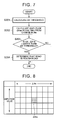
- FIG. 2 is a structural view schematically showing the configuration of the crank angle sensor according to the first embodiment of the invention.
- FIG. 3 is an example of a crank angle sensor signal.
- a crank rotor 102 that is rotated in a direction indicated by an arrow in the drawing is attached to a crankshaft 101. Tooth portions 102a that are formed at equal angular intervals of, for example, 10°CA, and a non-tooth portion 102b corresponding to a space of two consecutive teeth are provided on an outer periphery of the crank rotor 102, with a view to detecting a crank angle.
- the crank angle sensor 31 is configured to be equipped with a sensor unit 311 that faces the respective tooth portions 102a and detects a rotational speed of the crankshaft 101 by the tooth portions 102a, and a signal processing unit 312 that processes an output signal from the sensor unit 311.
- a crank angle sensor signal that is output from the sensor unit 311 becomes a pulse signal whose cycle corresponds to a period in which the crankshaft 101 rotates by a predetermined crank angle (e.g., 10°CA) when the rotational position of the crankshaft 101 is not a specific position set in advance, and becomes a non-tooth signal whose cycle corresponds to a period in which the crankshaft 101 rotates by, for example, 30°CA when the crankshaft 101 is at the specific position.
- the non-tooth signal is generated every time the crankshaft 101 rotates fully (i.e., by 360°CA).
- the signal processing unit 312 Upon receiving an output signal (see a crank angle sensor signal of FIG. 3 ) from the sensor unit 311, the signal processing unit 312 starts the operation of detecting a non-tooth signal in the crank angle sensor signal. Then, when it is first detected that the crank angle sensor signal has become a non-tooth signal, the signal processing unit 312 thereafter divides the crank angle sensor signal, and generates and outputs a 30°CA signal NE (see FIG. 1 ) as a pulse signal whose cycle corresponds to a period in which the crankshaft 101 rotates by 30° (i.e., which rises every time the crankshaft 101 rotates by 30°).
- the signal processing unit 312 outputs a reference position signal G at an end timing of the determination period. Accordingly, the reference position signal G rises when the rotational position of the crankshaft 101 reaches a position that is advanced by the predetermined cycle from the specific position where the non-tooth signal is generated.
- the ECU 20 identifies the cylinder of the engine 10 on the basis of the 30°CA signal NE, the reference position signal G and the like, and controls the engine 10.
- the reference position signal G is a pulse signal whose cycle corresponds to a period in which the camshaft rotates by 720° (i.e., a 720° CA signal).
- the crank angle sensor 31 detects rotation of the tooth portions 102a in accordance with a time variation (d ⁇ /dt) in the magnetic fluxes between the sensor unit 311 and the crank rotor 102.
- the output (a pulse amplitude) of the crank angle sensor 31 is an output corresponding to the rotational speed of the engine 10 (see the upper left section of FIG. 4 ).
- the distance between the sensor unit 311 and the crank rotor 102 fluctuates due to the influence of the rough road. Then, the output (the pulse amplitude) of the crank angle sensor 31 changes as a result of fluctuations in the distance between the sensor unit 311 and the crank rotor 102 as well as the presence/absence of the tooth portions 102a (see “ ⁇ X" in the upper right section of FIG. 4 ).
- the amplitude of the pulse output from the crank angle sensor 31 is influenced only by fluctuations in the rotational speed of the engine 10 (i.e., not influenced by the vehicle speed) (see the lower left section of FIG. 4 ).
- the amplitude of the pulse output from the crank angle sensor 31 increases as the vehicle speed increases (see the lower right section of FIG. 4 ).
- the rough road determination device 100 is configured to be equipped with the ECU 20 as an example of "the determination means" according to the invention, which determines whether or not the road on which the vehicle 1 travels is a rough road, by comparing a first amplitude fluctuation amount as an amplitude fluctuation amount of one pulse of an output of the crank angle sensor 31, which is determined in advance on the basis of a rotational speed of the engine 10, with a second amplitude fluctuation amount as an amplitude fluctuation amount of one pulse that is actually output from the crank angle sensor 31. That is, in this embodiment of the invention, the functions of the ECU 20 for various kinds of electronic control of the vehicle 1 are partially used as part of the rough road determination device 100.
- the ECU 20 first calculates a ⁇ X threshold as an example of "the first amplitude fluctuation amount" from a rotational speed and a load of the engine 10 and a map shown in, for example, FIG. 6 (step S101).
- FIG. 6 is an example of a map that prescribes the ⁇ X threshold.
- various known aspects can be applied to a method of detecting the rotational speed and the load of the engine 10. Therefore, the description of such a method is omitted herein.
- the ECU 20 determines whether or not an amplitude fluctuation amount ⁇ X of one pulse that is actually output from the crank angle sensor 31 (i.e., the second amplitude fluctuation amount) is larger than the calculated ⁇ X threshold (step S102).
- the ECU 20 determines that the road on which the vehicle 1 travels is a rough road (step S103), and ends the process.
- the ECU 20 ends the process.
- the case where the amplitude fluctuation amount ⁇ X is "equal" to the calculated ⁇ X threshold may be classified into one of the above-mentioned cases.
- the second embodiment of the rough road determination device will be described with reference to FIGS. 7 and 8 .
- the second embodiment of the invention is identical in configuration to the first embodiment of the invention except in part of the rough road determination process.
- the same description as in the first embodiment of the invention is omitted, and common components in the drawings are denoted by the same reference symbols respectively. Only the basic difference between these embodiments of the invention will be described with reference to FIGS. 7 and 8 .
- the ECU 20 first calculates a ⁇ X threshold from a rotational speed and a load of the engine 10 and a map shown in, for example, FIG. 6 (step S201). Subsequently, the ECU 20 calculates an amplitude fluctuation value ⁇ Xne resulting from a fluctuation in the rotational speed of the engine 10, from the fluctuation ( ⁇ Ne) in the rotational speed of the engine 10, an amplitude value of a pulse that is actually output from the crank angle sensor 31, and a map shown in, for example, FIG. 8 (step S202).
- FIG. 8 is an example of a map that prescribes the amplitude fluctuation value resulting from the fluctuation in the rotational speed of the engine.
- the ECU 20 ECU 20 determines whether or not a value ( ⁇ X- ⁇ Xne) obtained by subtracting the calculated amplitude fluctuation value ⁇ Xne from the amplitude fluctuation amount ⁇ X of one pulse that is actually output from the crank angle sensor 31 is larger than the calculated ⁇ X threshold (step S203).
- step S203 When it is determined that " ⁇ X- ⁇ Xne" is larger than the calculated ⁇ X threshold (Yes: step S203), the ECU 20 determines that the road on which the vehicle 1 travels is a rough road (step S204), and ends the process. On the other hand, when it is determined that " ⁇ X- ⁇ Xne" is smaller than the calculated ⁇ X threshold (No: step S203), the ECU 20 ends the process.
- the third embodiment of the rough road determination device according to the invention will be described with reference to FIGS. 9 and 10 .
- the third embodiment of the invention is identical in configuration to the second embodiment of the invention except in part of the rough road determination process.
- the same description as in the second embodiment of the invention is omitted, and common components in the drawings are denoted by the same reference symbols respectively. Only the basic difference between these embodiments of the invention will be described with reference to FIGS. 9 and 10 .
- the ECU 20 first calculates a ⁇ X threshold from a rotational speed and a load of the engine 10 and a map shown in, for example, FIG. 6 (step S301). Subsequently, the ECU 20 calculates an amplitude fluctuation value ⁇ Xne resulting from a fluctuation in the rotational speed of the engine 10, from the fluctuation ( ⁇ Ne) in the rotational speed of the engine 10, an amplitude value of a pulse that is actually output from the crank angle sensor 31, and a map shown in, for example, FIG. 8 (step S302).
- the ECU 20 determines whether or not a value ( ⁇ X- ⁇ Xne) obtained by subtracting the calculated amplitude fluctuation value ⁇ Xne from the amplitude fluctuation amount ⁇ X of one pulse that is actually output from the crank angle sensor 31 changes in accordance with a vehicle speed of the vehicle 1 (step S303).
- the ECU 20 first determines whether or not a value obtained by dividing " ⁇ X- ⁇ Xne" by the vehicle speed (i.e., "( ⁇ X- ⁇ Xne) / the vehicle speed") is larger than a threshold A that is specified by a map shown in, for example, FIG. 10 . Then, the ECU 20 determines that " ⁇ X- ⁇ Xne” changes in accordance with the vehicle speed of the vehicle 1, on the condition that "( ⁇ X- ⁇ Xne) / the vehicle speed" be larger than the threshold A.
- FIG. 10 is an example of a map that prescribes the threshold A.
- step S303 When it is determined that " ⁇ X- ⁇ Xne” changes in accordance with the vehicle speed of the vehicle 1 (Yes: step S303), the ECU 20 determines whether or not " ⁇ X- ⁇ Xne" is larger than the calculated ⁇ X threshold (step S304). When it is determined that " ⁇ X- ⁇ Xne" is larger than the calculated ⁇ X threshold (Yes: step S304), the ECU 20 determines that the road on which the vehicle 1 travels is a rough road (step S305), and ends the process.
- step S304 when it is determined that " ⁇ X- ⁇ Xne" is smaller than the calculated ⁇ X threshold (No: step S304), the ECU 20 ends the process. Besides, when it is determined that " ⁇ X- ⁇ Xne" does not change in accordance with the vehicle speed of the vehicle 1 as well (No: step S303), the ECU 20 ends the process.
Landscapes
- Engineering & Computer Science (AREA)
- Physics & Mathematics (AREA)
- Combustion & Propulsion (AREA)
- Chemical & Material Sciences (AREA)
- Mechanical Engineering (AREA)
- General Physics & Mathematics (AREA)
- General Engineering & Computer Science (AREA)
- Transportation (AREA)
- Mathematical Physics (AREA)
- Automation & Control Theory (AREA)
- Combined Controls Of Internal Combustion Engines (AREA)
- Control Of Driving Devices And Active Controlling Of Vehicle (AREA)
- Regulating Braking Force (AREA)
Applications Claiming Priority (1)
| Application Number | Priority Date | Filing Date | Title |
|---|---|---|---|
| PCT/JP2012/058120 WO2013145148A1 (fr) | 2012-03-28 | 2012-03-28 | Dispositif de détermination de route en mauvais état |
Publications (2)
| Publication Number | Publication Date |
|---|---|
| EP2832979A1 true EP2832979A1 (fr) | 2015-02-04 |
| EP2832979A4 EP2832979A4 (fr) | 2016-07-20 |
Family
ID=49258514
Family Applications (1)
| Application Number | Title | Priority Date | Filing Date |
|---|---|---|---|
| EP12873346.6A Withdrawn EP2832979A4 (fr) | 2012-03-28 | 2012-03-28 | Dispositif de détermination de route en mauvais état |
Country Status (6)
| Country | Link |
|---|---|
| US (1) | US10094849B2 (fr) |
| EP (1) | EP2832979A4 (fr) |
| JP (1) | JP5804193B2 (fr) |
| CN (1) | CN104136755B (fr) |
| BR (1) | BR112014021272B1 (fr) |
| WO (1) | WO2013145148A1 (fr) |
Families Citing this family (3)
| Publication number | Priority date | Publication date | Assignee | Title |
|---|---|---|---|---|
| US8716154B2 (en) | 2011-03-04 | 2014-05-06 | Applied Materials, Inc. | Reduced pattern loading using silicon oxide multi-layers |
| US9683916B2 (en) | 2015-06-12 | 2017-06-20 | Ford Global Technologies, Llc | Rough road simulation |
| JP7347219B2 (ja) | 2020-01-06 | 2023-09-20 | トヨタ自動車株式会社 | 道路診断システム |
Family Cites Families (13)
| Publication number | Priority date | Publication date | Assignee | Title |
|---|---|---|---|---|
| JPH03210049A (ja) * | 1990-01-13 | 1991-09-13 | Mazda Motor Corp | エンジンのクランク角検出装置 |
| JPH05312085A (ja) * | 1992-05-07 | 1993-11-22 | Nippondenso Co Ltd | 悪路検出装置 |
| WO1995027130A1 (fr) * | 1994-03-31 | 1995-10-12 | Mitsubishi Jidosha Kogyo Kabushiki Kaisha | Procede d'evaluation de terrain difficile pour vehicule a moteur a combustion interne |
| JP3203463B2 (ja) * | 1994-04-11 | 2001-08-27 | 株式会社ユニシアジェックス | 車両の悪路走行検出装置及び車両用エンジンの失火検出装置 |
| EP0795448A3 (fr) * | 1996-03-12 | 2000-01-19 | Unisia Jecs Corporation | Système de détection de l'état de la surface d'une route, pour véhicules automobiles |
| JP3303669B2 (ja) * | 1996-06-04 | 2002-07-22 | トヨタ自動車株式会社 | 内燃機関の空燃比制御方法 |
| JP3303739B2 (ja) * | 1996-12-19 | 2002-07-22 | トヨタ自動車株式会社 | 内燃機関の空燃比制御方法 |
| JP3486078B2 (ja) | 1997-09-16 | 2004-01-13 | 日信工業株式会社 | 車両のアンチロックブレーキ制御装置 |
| JP4173497B2 (ja) | 2005-06-15 | 2008-10-29 | 株式会社日立製作所 | 車両用内燃機関の制御装置および車両走行路面の悪路判定方法 |
| US7299687B2 (en) * | 2005-06-24 | 2007-11-27 | Gm Global Technology Operations, Inc. | Rough road detection system |
| US7591170B2 (en) * | 2007-01-23 | 2009-09-22 | Gm Global Technology Operations, Inc. | Rough road detection system |
| JP4433018B2 (ja) * | 2007-08-31 | 2010-03-17 | トヨタ自動車株式会社 | 内燃機関制御装置 |
| JP4623168B2 (ja) * | 2008-08-27 | 2011-02-02 | トヨタ自動車株式会社 | 内燃機関の失火検出装置および失火検出方法 |
-
2012
- 2012-03-28 CN CN201280070808.6A patent/CN104136755B/zh not_active Expired - Fee Related
- 2012-03-28 EP EP12873346.6A patent/EP2832979A4/fr not_active Withdrawn
- 2012-03-28 US US14/381,704 patent/US10094849B2/en active Active
- 2012-03-28 BR BR112014021272-4A patent/BR112014021272B1/pt not_active IP Right Cessation
- 2012-03-28 WO PCT/JP2012/058120 patent/WO2013145148A1/fr active Application Filing
- 2012-03-28 JP JP2014507116A patent/JP5804193B2/ja active Active
Also Published As
| Publication number | Publication date |
|---|---|
| WO2013145148A1 (fr) | 2013-10-03 |
| CN104136755B (zh) | 2016-10-12 |
| JP5804193B2 (ja) | 2015-11-04 |
| BR112014021272B1 (pt) | 2021-08-24 |
| CN104136755A (zh) | 2014-11-05 |
| EP2832979A4 (fr) | 2016-07-20 |
| JPWO2013145148A1 (ja) | 2015-08-03 |
| US10094849B2 (en) | 2018-10-09 |
| US20150025836A1 (en) | 2015-01-22 |
| BR112014021272A2 (pt) | 2017-06-20 |
Similar Documents
| Publication | Publication Date | Title |
|---|---|---|
| US20050229904A1 (en) | Regulating the mode of operation of an internal combustion engine | |
| EP2495421B1 (fr) | Dispositif de détection de raté d'allumage pour moteur à combustion interne | |
| EP3203058B1 (fr) | Dispositif de détermination de raté d'allumage | |
| US8027782B2 (en) | Pattern recognition for random misfire | |
| US10539483B2 (en) | Misfire detection device for internal combustion engine | |
| US10408151B2 (en) | Control device | |
| US10094849B2 (en) | Rough road determination device | |
| EP3480446B1 (fr) | Dispositif de détermination des ratés de moteur et véhicule | |
| US10139312B2 (en) | Method for sensing reverse rotation of engine in vehicle using tooth period ratio of crankshaft | |
| EP3480445B1 (fr) | Dispositif de détermination de raté d'allumage de moteur à combustion à intervalles inégaux et véhicule | |
| US20130275022A1 (en) | Engine crank signal correction method and controller | |
| JP2014084840A (ja) | 内燃機関の失火検出システム | |
| EP3530914B1 (fr) | Groupe moteur comprenant un moteur à combustion interne et un dispositif de detection de ratés d'allumage et véhicule | |
| JP2976684B2 (ja) | 車両用多気筒内燃機関の失火検出装置 | |
| JP2012188930A (ja) | エンジントルク推定装置 | |
| JP5018650B2 (ja) | 内燃機関の点火時期制御装置 | |
| JP2015059423A (ja) | 内燃機関の失火検出方法及び内燃機関失火検出装置 | |
| JP2007002814A (ja) | 内燃機関の失火検出装置 | |
| JP2004218605A (ja) | 内燃機関の失火検出装置 |
Legal Events
| Date | Code | Title | Description |
|---|---|---|---|
| PUAI | Public reference made under article 153(3) epc to a published international application that has entered the european phase |
Free format text: ORIGINAL CODE: 0009012 |
|
| 17P | Request for examination filed |
Effective date: 20140828 |
|
| AK | Designated contracting states |
Kind code of ref document: A1 Designated state(s): AL AT BE BG CH CY CZ DE DK EE ES FI FR GB GR HR HU IE IS IT LI LT LU LV MC MK MT NL NO PL PT RO RS SE SI SK SM TR |
|
| AX | Request for extension of the european patent |
Extension state: BA ME |
|
| DAX | Request for extension of the european patent (deleted) | ||
| RA4 | Supplementary search report drawn up and despatched (corrected) |
Effective date: 20160617 |
|
| RIC1 | Information provided on ipc code assigned before grant |
Ipc: F02D 45/00 20060101AFI20160613BHEP |
|
| STAA | Information on the status of an ep patent application or granted ep patent |
Free format text: STATUS: EXAMINATION IS IN PROGRESS |
|
| 17Q | First examination report despatched |
Effective date: 20190704 |
|
| STAA | Information on the status of an ep patent application or granted ep patent |
Free format text: STATUS: EXAMINATION IS IN PROGRESS |
|
| STAA | Information on the status of an ep patent application or granted ep patent |
Free format text: STATUS: THE APPLICATION IS DEEMED TO BE WITHDRAWN |
|
| 18D | Application deemed to be withdrawn |
Effective date: 20230307 |