EP2830505B1 - Hybrid pci system for medical radiographic imaging - Google Patents
Hybrid pci system for medical radiographic imaging Download PDFInfo
- Publication number
- EP2830505B1 EP2830505B1 EP13769560.7A EP13769560A EP2830505B1 EP 2830505 B1 EP2830505 B1 EP 2830505B1 EP 13769560 A EP13769560 A EP 13769560A EP 2830505 B1 EP2830505 B1 EP 2830505B1
- Authority
- EP
- European Patent Office
- Prior art keywords
- grating
- phase
- detector
- ray
- analyzer
- Prior art date
- Legal status (The legal status is an assumption and is not a legal conclusion. Google has not performed a legal analysis and makes no representation as to the accuracy of the status listed.)
- Not-in-force
Links
- 238000003384 imaging method Methods 0.000 title claims description 77
- LFEUVBZXUFMACD-UHFFFAOYSA-H lead(2+);trioxido(oxo)-$l^{5}-arsane Chemical compound [Pb+2].[Pb+2].[Pb+2].[O-][As]([O-])([O-])=O.[O-][As]([O-])([O-])=O LFEUVBZXUFMACD-UHFFFAOYSA-H 0.000 claims description 15
- 230000010363 phase shift Effects 0.000 claims description 13
- 238000010521 absorption reaction Methods 0.000 claims description 12
- 238000007493 shaping process Methods 0.000 claims description 8
- 230000008859 change Effects 0.000 claims description 7
- 238000000034 method Methods 0.000 description 57
- 238000010586 diagram Methods 0.000 description 32
- 238000009607 mammography Methods 0.000 description 27
- 230000005855 radiation Effects 0.000 description 13
- 230000033001 locomotion Effects 0.000 description 10
- 230000008569 process Effects 0.000 description 9
- 229910052710 silicon Inorganic materials 0.000 description 8
- 239000010703 silicon Substances 0.000 description 8
- XUIMIQQOPSSXEZ-UHFFFAOYSA-N Silicon Chemical compound [Si] XUIMIQQOPSSXEZ-UHFFFAOYSA-N 0.000 description 7
- 230000006870 function Effects 0.000 description 7
- 238000004519 manufacturing process Methods 0.000 description 7
- 238000001514 detection method Methods 0.000 description 6
- 230000000694 effects Effects 0.000 description 6
- 230000003287 optical effect Effects 0.000 description 6
- 230000008901 benefit Effects 0.000 description 5
- 210000000481 breast Anatomy 0.000 description 5
- 238000002059 diagnostic imaging Methods 0.000 description 5
- PCHJSUWPFVWCPO-UHFFFAOYSA-N gold Chemical compound [Au] PCHJSUWPFVWCPO-UHFFFAOYSA-N 0.000 description 5
- 229910052737 gold Inorganic materials 0.000 description 5
- 239000010931 gold Substances 0.000 description 5
- 230000010354 integration Effects 0.000 description 5
- 235000012431 wafers Nutrition 0.000 description 5
- 239000013078 crystal Substances 0.000 description 4
- 239000000463 material Substances 0.000 description 4
- 230000000737 periodic effect Effects 0.000 description 4
- 239000010948 rhodium Substances 0.000 description 4
- 238000001228 spectrum Methods 0.000 description 4
- 210000001519 tissue Anatomy 0.000 description 4
- 230000005540 biological transmission Effects 0.000 description 3
- 230000015572 biosynthetic process Effects 0.000 description 3
- 238000013461 design Methods 0.000 description 3
- 238000001914 filtration Methods 0.000 description 3
- 230000009467 reduction Effects 0.000 description 3
- 230000004044 response Effects 0.000 description 3
- 230000035945 sensitivity Effects 0.000 description 3
- ZOKXTWBITQBERF-UHFFFAOYSA-N Molybdenum Chemical compound [Mo] ZOKXTWBITQBERF-UHFFFAOYSA-N 0.000 description 2
- 230000004075 alteration Effects 0.000 description 2
- 210000000988 bone and bone Anatomy 0.000 description 2
- 238000006243 chemical reaction Methods 0.000 description 2
- 230000000295 complement effect Effects 0.000 description 2
- 238000006073 displacement reaction Methods 0.000 description 2
- 238000009826 distribution Methods 0.000 description 2
- 229910052750 molybdenum Inorganic materials 0.000 description 2
- 239000011733 molybdenum Substances 0.000 description 2
- 230000010355 oscillation Effects 0.000 description 2
- 238000000206 photolithography Methods 0.000 description 2
- 238000002360 preparation method Methods 0.000 description 2
- 238000012545 processing Methods 0.000 description 2
- 229910052703 rhodium Inorganic materials 0.000 description 2
- MHOVAHRLVXNVSD-UHFFFAOYSA-N rhodium atom Chemical compound [Rh] MHOVAHRLVXNVSD-UHFFFAOYSA-N 0.000 description 2
- 239000011669 selenium Substances 0.000 description 2
- 210000004872 soft tissue Anatomy 0.000 description 2
- 230000005469 synchrotron radiation Effects 0.000 description 2
- 230000002123 temporal effect Effects 0.000 description 2
- 238000013519 translation Methods 0.000 description 2
- 229910004613 CdTe Inorganic materials 0.000 description 1
- 229910004611 CdZnTe Inorganic materials 0.000 description 1
- BUGBHKTXTAQXES-UHFFFAOYSA-N Selenium Chemical compound [Se] BUGBHKTXTAQXES-UHFFFAOYSA-N 0.000 description 1
- BQCADISMDOOEFD-UHFFFAOYSA-N Silver Chemical compound [Ag] BQCADISMDOOEFD-UHFFFAOYSA-N 0.000 description 1
- 229910045601 alloy Inorganic materials 0.000 description 1
- 239000000956 alloy Substances 0.000 description 1
- 229910052782 aluminium Inorganic materials 0.000 description 1
- XAGFODPZIPBFFR-UHFFFAOYSA-N aluminium Chemical compound [Al] XAGFODPZIPBFFR-UHFFFAOYSA-N 0.000 description 1
- 229910021417 amorphous silicon Inorganic materials 0.000 description 1
- 230000003321 amplification Effects 0.000 description 1
- 238000013459 approach Methods 0.000 description 1
- 230000002238 attenuated effect Effects 0.000 description 1
- 210000000845 cartilage Anatomy 0.000 description 1
- 238000001444 catalytic combustion detection Methods 0.000 description 1
- 230000006835 compression Effects 0.000 description 1
- 238000007906 compression Methods 0.000 description 1
- 229910021419 crystalline silicon Inorganic materials 0.000 description 1
- 230000007812 deficiency Effects 0.000 description 1
- 230000000593 degrading effect Effects 0.000 description 1
- 230000001419 dependent effect Effects 0.000 description 1
- 230000005670 electromagnetic radiation Effects 0.000 description 1
- 238000009713 electroplating Methods 0.000 description 1
- 238000005516 engineering process Methods 0.000 description 1
- 239000000835 fiber Substances 0.000 description 1
- 235000013305 food Nutrition 0.000 description 1
- 238000005286 illumination Methods 0.000 description 1
- 238000007689 inspection Methods 0.000 description 1
- 230000003993 interaction Effects 0.000 description 1
- RQQRAHKHDFPBMC-UHFFFAOYSA-L lead(ii) iodide Chemical compound I[Pb]I RQQRAHKHDFPBMC-UHFFFAOYSA-L 0.000 description 1
- 210000004072 lung Anatomy 0.000 description 1
- 230000007246 mechanism Effects 0.000 description 1
- 229910052751 metal Inorganic materials 0.000 description 1
- 239000002184 metal Substances 0.000 description 1
- 150000002739 metals Chemical class 0.000 description 1
- 238000012986 modification Methods 0.000 description 1
- 230000004048 modification Effects 0.000 description 1
- 238000009659 non-destructive testing Methods 0.000 description 1
- 238000003199 nucleic acid amplification method Methods 0.000 description 1
- 230000000399 orthopedic effect Effects 0.000 description 1
- 230000037368 penetrate the skin Effects 0.000 description 1
- 230000000149 penetrating effect Effects 0.000 description 1
- 238000005293 physical law Methods 0.000 description 1
- 238000002601 radiography Methods 0.000 description 1
- 238000012216 screening Methods 0.000 description 1
- 229910052711 selenium Inorganic materials 0.000 description 1
- 229910052709 silver Inorganic materials 0.000 description 1
- 239000004332 silver Substances 0.000 description 1
- 239000010409 thin film Substances 0.000 description 1
- 238000003325 tomography Methods 0.000 description 1
- 238000012546 transfer Methods 0.000 description 1
- WFKWXMTUELFFGS-UHFFFAOYSA-N tungsten Chemical compound [W] WFKWXMTUELFFGS-UHFFFAOYSA-N 0.000 description 1
- 229910052721 tungsten Inorganic materials 0.000 description 1
- 239000010937 tungsten Substances 0.000 description 1
- 238000012800 visualization Methods 0.000 description 1
Images


Classifications
-
- A—HUMAN NECESSITIES
- A61—MEDICAL OR VETERINARY SCIENCE; HYGIENE
- A61B—DIAGNOSIS; SURGERY; IDENTIFICATION
- A61B6/00—Apparatus or devices for radiation diagnosis; Apparatus or devices for radiation diagnosis combined with radiation therapy equipment
- A61B6/40—Arrangements for generating radiation specially adapted for radiation diagnosis
- A61B6/4035—Arrangements for generating radiation specially adapted for radiation diagnosis the source being combined with a filter or grating
-
- A—HUMAN NECESSITIES
- A61—MEDICAL OR VETERINARY SCIENCE; HYGIENE
- A61B—DIAGNOSIS; SURGERY; IDENTIFICATION
- A61B6/00—Apparatus or devices for radiation diagnosis; Apparatus or devices for radiation diagnosis combined with radiation therapy equipment
- A61B6/06—Diaphragms
-
- A—HUMAN NECESSITIES
- A61—MEDICAL OR VETERINARY SCIENCE; HYGIENE
- A61B—DIAGNOSIS; SURGERY; IDENTIFICATION
- A61B6/00—Apparatus or devices for radiation diagnosis; Apparatus or devices for radiation diagnosis combined with radiation therapy equipment
- A61B6/48—Diagnostic techniques
- A61B6/484—Diagnostic techniques involving phase contrast X-ray imaging
-
- A—HUMAN NECESSITIES
- A61—MEDICAL OR VETERINARY SCIENCE; HYGIENE
- A61B—DIAGNOSIS; SURGERY; IDENTIFICATION
- A61B6/00—Apparatus or devices for radiation diagnosis; Apparatus or devices for radiation diagnosis combined with radiation therapy equipment
- A61B6/50—Apparatus or devices for radiation diagnosis; Apparatus or devices for radiation diagnosis combined with radiation therapy equipment specially adapted for specific body parts; specially adapted for specific clinical applications
- A61B6/502—Apparatus or devices for radiation diagnosis; Apparatus or devices for radiation diagnosis combined with radiation therapy equipment specially adapted for specific body parts; specially adapted for specific clinical applications for diagnosis of breast, i.e. mammography
-
- A—HUMAN NECESSITIES
- A61—MEDICAL OR VETERINARY SCIENCE; HYGIENE
- A61B—DIAGNOSIS; SURGERY; IDENTIFICATION
- A61B6/00—Apparatus or devices for radiation diagnosis; Apparatus or devices for radiation diagnosis combined with radiation therapy equipment
- A61B6/50—Apparatus or devices for radiation diagnosis; Apparatus or devices for radiation diagnosis combined with radiation therapy equipment specially adapted for specific body parts; specially adapted for specific clinical applications
- A61B6/508—Apparatus or devices for radiation diagnosis; Apparatus or devices for radiation diagnosis combined with radiation therapy equipment specially adapted for specific body parts; specially adapted for specific clinical applications for non-human patients
-
- G—PHYSICS
- G21—NUCLEAR PHYSICS; NUCLEAR ENGINEERING
- G21K—TECHNIQUES FOR HANDLING PARTICLES OR IONISING RADIATION NOT OTHERWISE PROVIDED FOR; IRRADIATION DEVICES; GAMMA RAY OR X-RAY MICROSCOPES
- G21K2207/00—Particular details of imaging devices or methods using ionizing electromagnetic radiation such as X-rays or gamma rays
- G21K2207/005—Methods and devices obtaining contrast from non-absorbing interaction of the radiation with matter, e.g. phase contrast
Definitions
- the application generally relates to digital x-ray imaging methods/system, and more specifically, to methods and/or systems for acquiring multiple image information of an object (e.g., medical radiographic imaging) using a grating-based differential phase contrast imaging technique with a slot-scanning configuration.
- an object e.g., medical radiographic imaging
- a grating-based differential phase contrast imaging technique with a slot-scanning configuration.
- PCI phase contrast imaging
- the principle of PCI is based on the wave nature of x-rays, where refraction and diffraction properties need to be considered.
- the x-ray is usually characterized by its frequency, amplitude, and phase.
- the imaginary part ⁇ contributes to the attenuation of the amplitude and the real part ⁇ is responsible for the phase shift. It has been shown that ⁇ is about 10 3 to 10 4 times larger than ⁇ . But in conventional medical imaging, only the information of ⁇ is recorded while the information of ⁇ is completely lost. In recent years, several PCI techniques have been explored to make use of the phase shift to form the image, which is expected to provide more information about the object. These include (i) the interferometer technique, (ii) the diffraction-enhanced imaging (DEI) technique, and (iii) the free-space propagation technique.
- DEI diffraction-enhanced imaging
- the three PCI techniques differ greatly in the way the image is recorded, the instrumental setup, and the requirements on the radiation source (especially its spatial and temporal coherence). Although some of the techniques yield excellent results for specific applications, none is very widely used and none has so far found application in medical diagnostics.
- the grating-based PCI method with a standard x-ray tube is limited by the loss of visibility of the interference fringes at the detector due to the broad spectrum of the x-ray tube.
- a standard polychromatic x-ray tube generates soft x-rays ( ⁇ 15 keV) that barely penetrate the skin at the low-energy portion of the spectrum, as well as hard x-rays (>50 keV) that penetrate through both bones and tissues at the high-energy portion of the spectrum.
- the use of an energy filter is thus preferred to obtain a narrow-bandwidth x-ray beam to reduce the radiation dose significantly by eliminating the unnecessary soft and hard x-rays and increase the clearness of the image.
- phase grating G1 and analyzer grating G2 are needed.
- a typical mammogram has a size of 24 cm x 30 cm. This means that a phase grating and an analyzer grating having the same size are required.
- the manufacturing cost of such large gratings will be extremely high.
- the phase contrast image quality is generally inferior in the edge regions of the detector.
- the angle subtended by the grating bars with the incoming x-ray beam becomes larger.
- the bar height of the phase and analyzer gratings increase approximately linearly with the x-ray energy (E)
- the aspect ratio of bar height to gap width would be very large (> 10:1 for E > 20 keV).
- these gratings would cause a shadowing effect of the phase grating and the scan effect of the analyzer grating at larger angles, degrading the image quality.
- US 2007 183 583 A1 relates to a focus-detector arrangement and an X-ray apparatus for generating projective or tomographic phase contrast recordings of a subject.
- the focus-detector arrangement includes a radiation source with a focus, arranged on a first side of the subject, for generating a fan-shaped or conical beam of rays.
- At least one X-ray optical grating is arranged in the beam path, with at least one phase grating arranged on the opposite second side of the subject in the beam path to generate an interference pattern of the X-radiation.
- An analysis-detector system detects at least the interference pattern generated by the phase grating in respect of its phase shift with position resolution.
- At least one X-ray optical grating includes bars which are free from overhangs that form shadows in the beam path of the fan-shaped or conical beam of rays.
- US 2009 092 227 A1 discloses an interferometer for X-rays, for obtaining quantitative phase contrast images.
- the interferometer includes a standard polychromatic X-ray source, a diffractive optical beam splitter other than a Bragg crystal in transmission geometry, and a position-sensitive detector with spatially modulated detection sensitivity.
- anti-scatter grid is the most widely used device for scatter rejection with most radiography and mammography systems.
- the amount of scattered radiation measured by the scatter-to-primary ratio can be reduced to between 0.1 and 0.3 from about 0.25 to 1.2.
- intrinsic to the anti-scatter grid method is the attenuation of a significant fraction of the primary x-rays.
- An aspect of this application is to advance the art of medical radiographic imaging.
- Another aspect of the application is to provide methods and/or apparatus embodiments for digital radiographic medical imaging. Another aspect of the application is to provide methods and/or apparatus embodiments for mammographic medical imaging. Another aspect of the application is to provide methods and/or apparatus embodiments for slot-scanning phase contrast imaging for large field of view (FOV) (e.g., greater than 100 mm square) radiographic medical imaging.
- FOV field of view
- a phase-contrast digital imaging system as set forth in claim 1 is provided. Further embodiments are inter alia disclosed in the dependent claims.
- the invention can inter alia provide a phase-contrast digital imaging system that can include a polychromatic x-ray source for radiographic imaging, a beam shaping assembly including a source grating G0 and a collimator configured to provide a long and narrow fan shaped x-ray beam having a beam length and a beam width.
- An x-ray grating interferometer comprises a phase grating G1, and an analyzer grating G2, wherein the phase grating G1 and the analyzer grating G2 are long and narrow and are covered by the beam length and the beam width.
- An area x-ray detector captures a radiographic image of an object placed between the source grating G0 and the phase grating G1.
- the x-ray detector has a long and narrow active area comprising an active length and an active width that are covered by the beam length and the beam width.
- the x-ray source, the source grating G0, the phase grating G1, the analyzer grating G2, and the detector are rigidly mounted to a swing arm.
- the swing arm is configured to pivot about an axis at the x-ray source to move the x-ray source, the source grating G0, the phase grating G1, the analyzer grating G2, and the detector about the axis to scan across the object while the object is in a stationary position.
- a pitch and a position of the analyzer grating G2 relative to a pitch of an interference pattern produced by the phase grating G1 produce at least one fringe pattern over a width of the analyzer grating G2.
- phase contrast imaging systems must meet various requirements including: (i) use of a standard broadband x-ray source; (ii) a large field of view (FOV) of many centimeters (e.g., 24 cm x 30 cm for a typical mammography system); (iii) a reasonably compact design comparable to current radiographic imaging systems (e.g., the source-to-detector distance is about 65 cm for a typical mammography system); and/or (iv) a reasonable exposure time and dose (e.g., the mean exposure for a typical mammography system is about 5 mR).
- FOV field of view
- centimeters e.g., 24 cm x 30 cm for a typical mammography system
- a reasonably compact design comparable to current radiographic imaging systems e.g., the source-to-detector distance is about 65 cm for a typical mammography system
- a reasonable exposure time and dose e.g., the mean exposure for a typical mammography system is about 5
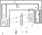
- FIG. 1 is a diagram that shows an exemplary embodiment of a slot-scanning phase-contrast imaging system in accordance with the application.
- a perspective view of a slot-scanning phase-contrast digital imaging system 100 can be used for mammography.
- the system 100 can include a conventional x-ray tube 110 for mammography imaging, a beam shaping assembly 120 comprising a filter or a tunable monochromator B, a collimator C, and a source grating G0, an x-ray grating interferometer 130 comprising a phase grating G1 and an analyzer grating G2, and an x-ray detector 140.
- the filter or a tunable monochromator B can be positioned after the collimator C.
- the three gratings e.g., G0, G1, and G2
- An object 150 e.g., a breast
- a supporting plate 152 can be supported by a supporting plate 152 and is compressed by a compression paddle 154, which can be moved and adjusted (e.g., vertically).
- FIG. 2 is a functional block diagram that shows an exemplary embodiment of a slot-scanning phase-contrast imaging system.
- FIG. 2 shows a functional block diagram of the imaging system 100 used for mammography.
- the x-ray tube 110, the beam shaping assembly 120, the grating interferometer 130, and the detector 140 can move with a prescribed three-dimensional relationship to a radiation source.
- the x-ray tube 110, the beam shaping assembly 120, the grating interferometer 130, and the detector 140 can be attached to a swing arm 160.
- the swing arm 160 can pivot around an axis co-axial with the focal spot of the x-ray tube 110.
- the x-ray tube 110 can be mounted at an angle with respect to the horizontal arm extension to illuminate an area of interest.
- the x-ray beam can be collimated to a narrow fan covering the interferometer 130 (e.g., gratings) and the active area of the detector 140 (e.g., about 24-cm long and 1-cm wide) by the collimator C.
- the entrance beam of the x-ray tube 110 can be slightly wider than the detector 140 and/interferometer 130 in order to reduce detector motion artifacts resulting from the edge of the detector 140 not being perfectly aligned with the collimator C at all times during the scan of an object.
- FIG. 3 is a diagram that shows a sectional illustration of an exemplary embodiment of components of a slot-scanning phase-contrast digital mammography imaging system in accordance with the application.
- FIG. 4 is a diagram that shows a sectional illustration of another exemplary embodiment of components of a slot-scanning phase-contrast digital mammography imaging system in accordance with the application.
- One difference between the imaging system of FIG. 3 and the imaging system shown in FIG. 4 is that the orientation of the grating bars of the gratings (e.g., the three gratings G0, G1, and G2) in FIG. 4 are parallel to the scan direction of the swing arm 160 (e.g., the x-ray fan beam), instead of being perpendicular to the scan direction of the swing arm 160 in FIG. 3 .
- the x-ray source 110 can be a conventional x-ray source.
- the x-ray source 110 can be a polychromatic x-ray tube for mammography imaging.
- the x-ray source 110 can have a rotating anode made of tungsten (W), molybdenum (Mo), rhodium (Rh), or an alloy of heavy-element materials.
- the area of the focal spot can be between 0.01 mm 2 and 1.0 mm 2 .
- additional filtration can be optionally used to spectrally shape the x-ray beam into a narrow-bandwidth beam to reduce or eliminate the unnecessary soft x-rays that are mostly absorbed by the patient and contribute to the radiation dose received during the examination, and/or the hard x-rays that can reduce the quality of the image.
- Exemplary typical filter materials are aluminum (Al), molybdenum (Mo), rhodium (Rh), silver (Ag), and other metals.
- the filter B can be a tunable monochromatic x-ray filter that can be used with a divergent polychromatic x-ray source to produce monochromatic x-rays with a narrow spectrum centered at a selectable energy with a bandwidth of 1-3 keV.
- the imaging system 100 can include three gratings.
- the source grating G0 can have absorbing gold bars
- the phase grating G1 can be made of silicon
- the analyzer grating G2 can be made of absorbing gold bars.
- the source grating G0 can be placed close to the x-ray source 110.
- the second grating G1 and the third grating G2 can have a fixed distance in between, for example, by being mechanically coupled together, electromechanically connected or rigidly coupled together.
- the source grating G0 and the interferometer 130 can be coupled to have a variable, but known distance therebetween.
- the source grating G0 can allow the use of a large incoherent x-ray source as the x-ray source 110 because the source grating G0 can create an array of individual line sources that each can provide sufficient spatial coherence for the interferometric contrast.
- the images created by the source grating G0 generated line sources can be superimposed congruently in the detector plane at the detector 140 leading to a gain in intensity (e.g., controllable interference).
- the phase grating G1 can operate as a beam splitter and divide the incoming beam essentially into the ⁇ 1 diffraction orders. These two ⁇ 1 diffracted beams can interfere and form a periodic interference pattern in the plane of the second grating G2 through the Talbot self-imaging effect.
- an analyzer second grating G2 can be placed at a specific Talbot distance from the phase first gating G1 to enable the transform of fringe positions into intensity modulations on the detector 140 located directly behind the second grating G2 with the phase stepping technique.
- the size the source grating G0 can be small (e.g., about 1 cm x 0.5 cm) because of the small angle subtended by the x-ray fan.
- the FOV can be 24 cm x 30 cm. Since the object is located close to the interferometer formed by gratings G1 and G2, the size of these gratings should match the FOV. Given the state of art for standard photolithography techniques, repeatable fabrications of such large-area gratings G1 and G2 (e.g., 24 cm x 30 cm) with high or sufficient yield and an acceptable uniformity are not trivial.
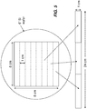
- a standard 6 or 8 inch-silicon wafer can be used to fabricate multiple small gratings (e.g., each with an area of 8 cm x 1 cm) within a square of 8 cm x 8 cm.
- a long and narrow grating e.g., 24 cm x 1 cm
- FIG. 5 is a diagram that shows an embodiment of a long and narrow grating (e.g., formed by abutting two or more small gratings together) according to the application.
- a long and narrow grating e.g., formed by abutting two or more small gratings together
- one embodiment of the G1 grating or G2 grating can be formed using a standard silicon wafer.
- a standard 8" wafer can be used to provide the long and narrow gratings G1 and G2.
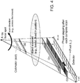
- FIG. 6 is a diagram that shows a schematic of an exemplary three-grating phase contrast imaging system (e.g., interferometer).
- three gratings namely, the source grating G0 having absorbing gold bars, phase grating (or beam splitter) G1 made of silicon, and analyzer grating G2 having absorbing gold bars are used.
- the gratings are made from silicon wafers using standard photolithography techniques, and subsequently electroplating to fill the grooves with gold (G0 and G2).
- the interferometer is formed by G1 and G2. The plane and the grating bars of these three gratings are parallel to each other.
- the source grating G0 allows the use of large incoherent x-ray sources since it creates an array of individual line sources each providing enough spatial coherence for the interferometric contrast.
- the images created by each line source are superimposed congruently in the detector plane leading to a gain in intensity.
- the phase grating G1 acts as a beam splitter and divides the incoming beam essentially into two first diffraction orders that interfere and form periodic fringe patterns in planes perpendicular to the optical axis (z). Based on the Talbot effect, the periodic fringe pattern, which is called the self image of the phase grating G1, will have its highest contrast at the first Talbot distance d 1 behind G1.
- the period of the fringe pattern (p 2 ) at the plane of the analyzer grating G2 placed at a distance of d 1 from G1 is approximately half the period of G1.
- the analyzer grating G2 has approximately the same period of the fringe pattern (p 2 ).
- the incoming x-ray wavefront can be locally distorted by the object.
- the fringes formed by the phase grating G1 are displaced from their unperturbed positions.
- the fringe displacements are transformed into intensity variations by the analyzer grating G2 placed at a distance d 1 from the phase grating G1. This allows the use of an x-ray detector placed just behind the analyzer grating G2 with much larger pixels than the spacing of the fringes.
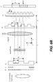
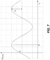
- FIG. 7 is a diagram that shows intensity variation for one detector pixel (i, j) when one of the gratings (e.g., G2) is scanned along x g and the corresponding Fourier series coefficients a, b, and ⁇ .
- the phase ⁇ of the oscillation in each pixel is a measure of the wavefront phase gradient, while the average detector signal a in each pixel over the grating scan is equivalent to the conventional absorption image.
- the total phase shift of the object can thus be retrieved by a single one-dimensional integration along the direction x.
- FIG. 6B is a diagram that shows a schematic of another exemplary three-grating phase contrast imaging system.
- a three-grating PCI system can include stationary G0, G1, and G2 gratings and an object to be imaged can be moved (e.g., across) relative to the stationary G0, G1, and G2 gratings.
- F is optional additional filtration
- C is an optional collimator or beam shaping apparatus.
- An indirect flat panel detector can include a layer of scintillator made of CsI, Gd 2 O 2 S, or other scintillating phosphors coupled with an array of photodiodes (e.g., a-Si photodiodes) and switches (e.g., thin-film transistor (TFT) switches).
- the thickness of the scintillator layer can be between 80 um and 600 um.
- the pixel pitch of the detector is ranged from 20 to 200 um.
- a direct detector can include a photoconductor such as amorphous selenium (a-Se) or PbI 2 to produce electrical charges on the detection of an x-ray.
- a-Se amorphous selenium
- PbI 2 amorphous selenium
- a charge-coupled device (CCD) based x-ray detector can be used as the detector 140.
- the CCD based x-ray detector can include a scintillating screen.
- a tiled CCD detector array operated in time delay integration (TDI) mode is preferred to enable continuous scanning motion and x-ray illumination during each scan.
- the detector array can be formed by tiling two or more CCD devices together and can be coupled to a scintillator layer and a fiber optic plate (FOP).
- the FOP is used to protect the CCD array from radiation damage.
- a slot-scanning system with a beam width comparable to the pixel width would require an extremely high tube output.
- the TDI operating mode of the CCD can allow a significantly wider beam to be used.
- the detected x-rays are first transformed into light photons via the scintillator layer.
- the light photons are then transmitted to the CCD through the FOP producing electrons in the CCD in response to the light emission from the scintillator upon x-ray absorption.
- the TDI mode can enable x-ray integration across the CCD width while maintaining the pixel resolution.
- the detector array can include four CCDs, each having a size of 6 cm x 1 cm, abutted along their narrow dimension to form a long and narrow detector (e.g., 24 cm x 1 cm).
- the typical pixel size is between 20 um and 200 um.
- a linear photon counting gaseous detector using avalanche amplification process can be also used as the detector 140.
- crystalline Si, CdTe, and CdZnTe can also be used in direct-conversion photon-counting detectors.
- This exemplary single photon counting detection technique can discriminate noise in the detector 140 from a true x-ray photon interaction. By counting signals above a predefined threshold, an electronic noise free and efficient counting of single x-ray photons is achieved.
- this detector type is used in a slot-scanning system according to embodiments of the application, significant reduction of patient dose and scattered radiation and/or a considerable increase in image quality in terms of contrast and spatial resolution can be obtained, as compared to the integrating detectors (such as direct and indirect flat-panel detectors and CCD devices).
- grating parameters and the geometric system parameters in exemplary embodiments can be restricted by the choice of x-ray source, the limitation of the grating fabrication process, the practicality of the system size, the system performance requirements, and the conformation of physical laws.
- the system parameters and grating parameters should satisfy the following equations.
- the structure height of the silicon phase grating G1 has to be such that the x-rays passing through the grating bars undergo a prescribed phase shift or a phase shift of ⁇ (as an example), which results in the splitting of the beam into the ⁇ 1 diffraction orders.
- h 1 ⁇ 2 ⁇ S i
- the structure height of gratings G0 and G2 should be large enough to provide sufficient absorption of x-ray (e.g., > 75%) for selected or optimum system performance.
- n By first selecting n, p 2 , ⁇ , and L based on system requirements and limitations on grating fabrication, other parameters, namely, s, p 0 , p 1 , h 1 , h 2 , h 3 , and d n can then be determined.
- Table 1 lists exemplary system design parameters and grating parameters for an embodiment of a slot-scanning phase-contrast digital mammography system.
- FIG. 8 is a flow chart that shows an embodiment of a method for operating a slot-scanning phase-contrast digital imaging system.
- the exemplary method embodiment of FIG. 8 will be described using and can be implemented by the system embodiment shown in FIG. 1 and FIG. 3 , however the method is not intended to be so limited.
- the detector is initialized in preparation for exposure and the analyzer grating G2 is moved to a prescribed position or home position (operation block 810). Then, for mammographic medical images, the breast can be compressed (e.g., to improve image quality) (operation block 820).
- the swing arm 160 is set to an initial or home position (operation block 830).
- block 830 can position the x-ray tube 110, the beam shaping assembly 120, the x-ray grating interferometer 130 and the x-ray detector 140 that can be rigidly mounted to the swing arm 160.
- the x-ray beam can be scanned across the object as the swing arm 160 rotates in an arc like a pendulum covering the width of the object (e.g., about 30 cm) as shown in FIG. 3 .
- the image data recorded by the detector 140 can be read out and stored in a memory unit of a computer (e.g., at the slot-scanning phase-contrast digital imaging system or at a wirelessly coupled control console having a processor, display and memory.
- the detector is a long and narrow CCD based detector and can operate in the time delay integration (TDI) mode for signal detection.
- TDI time delay integration
- the analyzer grating G2 e.g., mounted on a piezo translation stage
- the analyzer grating G2 is then moved laterally by a predetermined distance (step) before the next scan of the x-ray beam starts (operation block 860) and the process jumps back to block 830 where the swing arm 160 is returned to the initial pre-scan position or home position (or reversed in rotational direction) to be ready for the next scan in the image series.
- the image data set can be extracted, processed, and displayed on a monitor (operation blocks 870, 880, 890).
- N e.g., typically 5 to 8
- the same image data set can be processed by an image processing unit of the computer to construct multiple images of the object including absorption contrast, differential phase contrast, phase shift contrast, and dark-field images, as described herein.
- Exemplary alternate phase stepping implementations include but are not limited to: (i) moving grating G1 (instead of G2) in the direction perpendicular to both the optical axis and the grating bars of G1; (ii) rotating G1 and G2 together around an axis along the orientation of grating bars by an angle (e.g., the two gratings are kept in an aligned position with respect to each other or are fixed together mechanically); or (iii) moving the x-ray source in the direction perpendicular to both the optical axis and the grating bars of the gratings.
- These exemplary alternate phase stepping implementations can be implemented on the exemplary swing arm 160 configuration shown in FIG. 3 .
- FIG. 9 is a flow chart that shows an embodiment of a method for operating a slot-scanning phase-contrast digital imaging system.
- the exemplary method embodiment of FIG. 9 will be described using and can be implemented by the system embodiment shown in FIG. 1 and FIGS. 3-4 , however the method is not intended to be so limited.
- Fig. 9 shows another "step-dither-step" mode of system operations where the swing arm can scan across the object in a step-wise motion. The distance of each step can be about the width of the detector.
- a series of x-ray exposure/image capture operations can be performed (e.g., N images captured) using the aforementioned phase stepping technique (e.g., move the analyzer grating G2 by p 2 /N).
- the swing arm moves to the next step position and another series of x-ray exposure/image capture operations is performed until the swing arm steps through and completes the whole object scan.
- the raw image data set is extracted, processed, and displayed on a monitor.
- the raw images data subset can be extracted at the end of each "step", and the captured raw images can be processed and displayed on a monitor concurrently or at the completion of the last step.
- the detector is initialized in preparation for exposure and the analyzer grating G2 is moved to a prescribed position or home position (operation block 910). Then, an object can be positioned or for mammographic medical images, the breast can be compressed (e.g., to improve image quality) (operation block 920).
- the swing arm 160 is set to an initial or home position (operation block 930).
- the swing arm 160 is stepped to a current step position (operation block 933), the x-ray beam is fired to expose and capture an image of a portion of the object (operation block 940). Then, it is determined whether the image series is complete for that step (e.g., N images have been captured) in operation block 945.
- the image data set can be stored and it can be determined in operation block 955 whether scanning is complete for the whole object.
- N e.g., typically 5 to 8
- the swing arm 160 is stepped to the next position (operation block 933) and operation blocks 940, 945 and 950 can be repeated.
- the image data set can be extracted, processed, and displayed on a monitor (operation blocks 960, 965, 970).
- the same image data set can be processed by an image processing unit of the computer to construct multiple images of the object including absorption contrast, differential phase contrast, phase shift contrast, and dark-field images, as described herein.
- the fringe displacements are transformed into intensity values by an analyzer grating G2 placed at a distance d n from the phase grating G1.
- a two-dimensional detector with much larger pixels than the spacing of the fringes can be used to record the signal. Scanning the lateral position x g of one of the gratings (e.g., the analyzer grating G2) causes the recorded signal in each pixel to oscillate as a function of x g .
- the signal oscillation curve can be expressed by a Fourier series, I s i , j , x g ⁇ a s i , j + b s i , j cos 2 ⁇ p 2 x g + ⁇ s i , j (with the object) I b i , j , x g ⁇ a b i , j + b b i , j cos 2 ⁇ p 2 x g + ⁇ b i , j (without the object)
- a dark-field image is formed from higher-angle diffraction intensities scattered by the object.
- the information about the scattering power of the object is contained in the first Fourier amplitude coefficient, bs(i, j) of Is(i, j, x g ).
- These four different images of the object can be derived from the same data set and can be complementary to each other to provide multiple information of the object enabling the visualization of subtle details in the object.
- Embodiments of phase-contrast digital imaging systems and/or methods of using the same can provide various advantages according to the application.
- Embodiments of a hybrid slot-scanning grating-based differential phase contrast mammography system have various advantages (e.g., compared to a full-field digital mammography system).
- Embodiments of a grating-based differential phase contrast imaging technique can use conventional x-ray tubes instead of expensive and huge synchrotron radiation sources to provide multiple image information (e.g., absorption contrast image, differential phase contrast image, phase shift image, and dark-field image) of the object from a single image capture process.
- image information e.g., absorption contrast image, differential phase contrast image, phase shift image, and dark-field image
- Embodiments of slot-scanning grating-based differential phase contrast systems and/or methods can significantly enhance the contrast of low absorbing tissues (e.g., the contrast between healthy and diseased tissues), which can be especially useful for mammography and orthopedic joints.
- low absorbing tissues e.g., the contrast between healthy and diseased tissues
- Embodiments of slot-scanning grating-based differential phase contrast systems and/or methods can allow the use of small gratings and detectors to produce a large-area image. Embodiments can provide reduction in motion blur, scattered radiation, and patient dose without using a grid.
- Embodiments of slot-scanning grating-based differential phase contrast systems and/or methods can use a phase grating (G1) and an analyzer grating (G2) with a long and narrow geometry that can be formed by abutting two or more short and narrow (e.g., 8 cm x 1 cm) gratings together and will cost significantly lower than the ones with a large full-field size (24 cm x 30 cm for typical mammography).
- a tiled detector can be made and will cost much less than a large full-field two-dimensional detector (e.g., 24 cm x 30 cm for typical mammography).
- Embodiments of an imaging system can require a long and narrow detector, which can be formed by abutting two or more short and narrow (e.g., 8 cm x 1 cm) detectors together. Smaller detectors with high sensitivity and low noise are commercially available at low cost relative to a large full-field two-dimensional detector (24 cm x 30 cm for typical mammography).
- Embodiments of slot-scanning grating-based differential phase contrast systems and/or methods can use curved gratings and detectors circularly around the source focus to enable the design of a more compact system and reduce or eliminate the shadowing effect of the phase grating and/or the scan effect of the analyzer grating occurred in the edge regions of the image.
- Fig. 10 is a diagram that shows a side view of an embodiment of slot-scanning grating-based differential phase contrast system using curved gratings and detectors that correspond to the x-ray source focus.
- Embodiments of slot-scanning grating-based differential phase contrast systems and/or methods can use an x-ray tube with rotating-anode (higher output), a short distance between the x-ray source and the object (higher x-ray fluence), and a detector with a CsI scintillator coupled with a tiled TDI-mode CCD array (higher detection sensitivity). As a result, the exposure time can be significantly reduced.
- Certain exemplary embodiments for slot-scanning phase-contrast digital imaging systems and/or methods for using the same can employ step-dither-step approaches, where one of the gratings, either phase grating G1 or analyzer grating G2, can be stepped with respect to another.
- one of the gratings either phase grating G1 or analyzer grating G2
- N is a number of steps (e.g., using a piezo translational stage) required to cover a period of grating G2
- the lateral size of the grating G2 is l G2
- the scan of an object with lateral size S can use or require S / l G2 ⁇ N of x-ray exposures.
- Both exemplary scanning embodiments described in Figures 8 and 9 have either the swing arm or the analyzer grating G2 return back to its initial (e.g., home) position after one slice of the object is scanned.
- precision positioning of these devices e.g., translational piezo drivers
- the multiple forward-backward types of motions can add up to significant spatial errors after the whole object scan is complete.
- continuous motion of the swing arm with minimal or no stepping of the analyzer grating is preferable. It is also preferable when the relative position of the gratings G1 and G2 does not change (e.g., no stepping) and/or the swing arm continuously moves across the object, which can reduce a scanning time.
- a detuned phase contrast imaging system can be understood to be an imaging system in which the pitch p 2 of the analyzer grating G2 is purposely controlled or fabricated to be unequal to a period of interference pattern p int at a Talbot distance behind the phase grating G1.
- a detuned phase contrast imaging system can be understood to be an imaging system in which the pitch p 2 of the analyzer grating G2 is controlled or fabricated to be equal to a period of interference pattern p int at a Talbot distance behind the phase grating G1, but the analyzer grating G2 is positioned away from the corresponding Talbot distance.
- a detuned phase contrast imaging system can generate a periodic fringe pattern, where the fringe pattern occurs over a width or a portion of the width of the analyzer gating G2.
- FIG. 11 is a diagram that illustrates concepts of exemplary tuned and detuned phase contrast imaging systems.
- Exemplary values of f 0 in indirect charge integrating detectors can be typically between 1 and 2 cyc/mm, while value of f 0 can reach 5 cyc/mm in the case of direct photon counting detectors. That said, the detector will measure no signal at 1000 cyc/mm.
- the only detectable signal is: M T F f ⁇ cos 2 ⁇ f int ⁇ f 2 x / 2
- the signal is increased or maximum.
- the detector yields the uniform image.
- Figure 12 is a diagram that illustrates examples of the open field images measured in the detector plane for tuned and detuned configurations of a phase contrast imaging system embodiment.
- an open field image for a tuned phase contrast imaging system embodiment can produce an unchanging or flat open field image across the analyzer grating G2.
- the lateral size of an image is chosen to be equal to one period of fringe pattern as an example.
- the phase contrast imaging system, ⁇ f can be ⁇ 5 %, ⁇ 1 % or ⁇ 0 . 1 %.
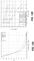
- FIG. 13A shows several MTFs plotted for different alpha slope (e.g., see equation 16).
- the MTF with a higher value of slope can have a longer plateau (e.g., slower reduction) for a spatial frequency below the half value frequency.
- the higher slope is typical for a detector with a better frequency response, for example direct conversion photon-counting detector in comparison to indirect detector.
- the slope ⁇ is typically close to 1 and higher, while the half value frequency is in the range between 1.5 and 2 cyc/mm.
- FIG. 13B shows the percentage of the contrast drop as a function of MTF slope ⁇ and spatial frequency f 0 .
- the drop in contrast relative to the maximum possible is less for smaller ⁇ f .
- the curves shown in Figure 13 get even lower for higher f 0 (e.g., for a detector with higher quantum efficiency).
- Higher MTF slope ⁇ can further reduce the drop in contrast.
- the MTF slope ⁇ is typically close to 1 and higher.
- embodiments of detuned system can only be implemented according to schematics shown in Figure 3 .
- the fringe patters in the detector plane has to be oriented such that the arms swings laterally across the pattern.
- PCI implementation depicted on Figure 4 is suitable for tuned phase contrast imaging system, it cannot be applied to detuned PCI system.
- the analyzer grating G2 and the detector D can be moved together (e.g., using an attached translational piezo driver) to simultaneously move them in the direction of the x-ray beam (e.g., z axis) such that the frequency ( ⁇ f ) of fringe pattern in the detector plane can be adjusted.
- the phase contrast imaging system can be tweaked by shifting the analyzer grating G2 along the beam axis (e.g., axis z) relative to the phase grating G1.
- the analyzer grating G2 can peak at different z position of the interference pattern formed by phase grating G1.
- the different frequency of interference pattern, f int is used to form the desired fringe pattern at the detector plane.
- the phase retrieval algorithm can require multiple x-ray exposures at different lateral positions of analyzer grating, which allows forming a cosine shaped intensity curve shown in Figure 7 .
- the detector can already measure the cosine shaped fringe pattern and the grating stepping is no longer required.
- the grating G1, the grating G2 and the detector D can be fixed at one relative position and moved to image the object, for example attached to a swing arm, and the swing arm can be continuously moved across the stationary object.
- the swing arm can be at rest and the object can be laterally moved across in the plane perpendicular to incident x-rays.
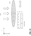
- Figure 14 is a diagram that illustrates exemplary motion of interferometer with respect to objects or vise versa for a phase contrast imaging system embodiment.
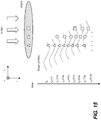
- Figure 15 is a diagram that illustrates exemplary of object scan schematics that project individual slices of the object onto one-period fringe pattern measured in the detector plane.
- Triangle, circle, and square shapes shown in Figures 14-15 refer to different parts of the exemplary object.
- each individual part of the object such as triangle, circle and square
- N 8
- each of the exemplary shapes e.g., triangle, circle, and square
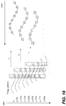
- Figure 16 shows the schematics of intensity curve formation for an individual slice of the object (e.g., triangles, circles, and squares).
- the Fourier based reconstruction technique described herein, can be applied to each of the intensity curves to form the transmission, differential phase, and dark-field images for each of the slices. Then the slice images can be combined or stitched together to form image(s) of the full object.
- methods can include providing an x-ray generator for radiographic imaging, providing a beam shaping assembly comprising a beam limiting apparatus and a source grating G0, providing an x-ray grating interferometer comprising a phase grating G1, and an analyzer grating G2, and offsetting a pitch of the analyzer grating G2 relative to a pitch of an interference pattern produced by the phase grating G1 at a prescribed distance from the phase grating G1.
- the relative position of the phase gratings G1 and the analyzer grating G2 does not change for a scan of an object, and where the prescribed distance is a Talbot distance.
- One method embodiment can include producing a fringe pattern that is greater than 0.1 cm or over a significant portion of the analyzer grating G2.
- the grating G1, the grating G2 and the detector D can be fixed at one relative position, attached to the swing arm and moved to image the object, where the relative position of the grating G1 and the grating G2 provide a non-zero ⁇ f .
- a fringe pattern is produced by the pitch of the analyzer grating G2 being unequal to the pitch of an interference pattern produced by the phase grating G1 at a position of the analyzer grating G2, or the fringe pattern is produced by the position of the analyzer grating G2 being offset from a Talbot distance when the pitch of the analyzer grating G2 is equal to a pitch of the interference pattern.
- Embodiments of slot-scanning grating-based differential phase contrast systems and/or methods can provide a wide range of potential applications including medical imaging, small-animal imaging, security screening, industrial non-destructive testing, and food inspection.
- Embodiments according to the application can also be used for phase-contrast applications using other forms of radiation such as neutron and atom beams.
- Embodiments according to the application can provide a robust and low-cost phase-contrast mammography system with high efficiency and large field of view for clinical applications.
Landscapes
- Health & Medical Sciences (AREA)
- Life Sciences & Earth Sciences (AREA)
- Medical Informatics (AREA)
- Engineering & Computer Science (AREA)
- Radiology & Medical Imaging (AREA)
- Molecular Biology (AREA)
- Biophysics (AREA)
- Nuclear Medicine, Radiotherapy & Molecular Imaging (AREA)
- Optics & Photonics (AREA)
- Pathology (AREA)
- Physics & Mathematics (AREA)
- Biomedical Technology (AREA)
- Heart & Thoracic Surgery (AREA)
- High Energy & Nuclear Physics (AREA)
- Surgery (AREA)
- Animal Behavior & Ethology (AREA)
- General Health & Medical Sciences (AREA)
- Public Health (AREA)
- Veterinary Medicine (AREA)
- Dentistry (AREA)
- Oral & Maxillofacial Surgery (AREA)
- Apparatus For Radiation Diagnosis (AREA)
- Measurement Of Radiation (AREA)
Applications Claiming Priority (3)
| Application Number | Priority Date | Filing Date | Title |
|---|---|---|---|
| US201261617948P | 2012-03-30 | 2012-03-30 | |
| US13/724,037 US20130259194A1 (en) | 2012-03-30 | 2012-12-21 | Hybrid slot-scanning grating-based differential phase contrast imaging system for medical radiographic imaging |
| PCT/US2013/026301 WO2013148010A1 (en) | 2012-03-30 | 2013-02-15 | Hybrid pci system for medical radiographic imaging |
Publications (3)
| Publication Number | Publication Date |
|---|---|
| EP2830505A1 EP2830505A1 (en) | 2015-02-04 |
| EP2830505A4 EP2830505A4 (en) | 2016-01-06 |
| EP2830505B1 true EP2830505B1 (en) | 2018-08-29 |
Family
ID=49235030
Family Applications (1)
| Application Number | Title | Priority Date | Filing Date |
|---|---|---|---|
| EP13769560.7A Not-in-force EP2830505B1 (en) | 2012-03-30 | 2013-02-15 | Hybrid pci system for medical radiographic imaging |
Country Status (5)
| Country | Link |
|---|---|
| US (2) | US20130259194A1 (enExample) |
| EP (1) | EP2830505B1 (enExample) |
| JP (1) | JP6177306B2 (enExample) |
| CN (1) | CN104244832A (enExample) |
| WO (1) | WO2013148010A1 (enExample) |
Families Citing this family (33)
| Publication number | Priority date | Publication date | Assignee | Title |
|---|---|---|---|---|
| US9724063B2 (en) | 2012-12-21 | 2017-08-08 | Carestream Health, Inc. | Surrogate phantom for differential phase contrast imaging |
| US9001967B2 (en) * | 2012-12-28 | 2015-04-07 | Carestream Health, Inc. | Spectral grating-based differential phase contrast system for medical radiographic imaging |
| US9700267B2 (en) | 2012-12-21 | 2017-07-11 | Carestream Health, Inc. | Method and apparatus for fabrication and tuning of grating-based differential phase contrast imaging system |
| US9357975B2 (en) * | 2013-12-30 | 2016-06-07 | Carestream Health, Inc. | Large FOV phase contrast imaging based on detuned configuration including acquisition and reconstruction techniques |
| CN104869905B (zh) * | 2012-12-21 | 2019-08-06 | 卡尔斯特里姆保健公司 | 基于微分相衬成像的医疗放射照相光栅 |
| US10578563B2 (en) | 2012-12-21 | 2020-03-03 | Carestream Health, Inc. | Phase contrast imaging computed tomography scanner |
| US10096098B2 (en) | 2013-12-30 | 2018-10-09 | Carestream Health, Inc. | Phase retrieval from differential phase contrast imaging |
| US9907524B2 (en) * | 2012-12-21 | 2018-03-06 | Carestream Health, Inc. | Material decomposition technique using x-ray phase contrast imaging system |
| US9494534B2 (en) | 2012-12-21 | 2016-11-15 | Carestream Health, Inc. | Material differentiation with phase contrast imaging |
| CN105103238B (zh) * | 2013-11-28 | 2017-03-08 | 皇家飞利浦有限公司 | 用于谱滤波的基于泰伯效应的近场衍射 |
| WO2015122542A1 (en) * | 2014-02-14 | 2015-08-20 | Canon Kabushiki Kaisha | X-ray talbot interferometer and x-ray talbot interferometer system |
| DE102014203811B4 (de) * | 2014-03-03 | 2019-07-11 | Siemens Healthcare Gmbh | Ergänzungssystem zur interferometrischen Röntgenbildgebung und projektive Röntgenvorrichtung |
| JP2016050891A (ja) * | 2014-09-01 | 2016-04-11 | キヤノン株式会社 | X線撮像装置 |
| DE102014221599A1 (de) * | 2014-10-23 | 2016-04-28 | Siemens Aktiengesellschaft | Vorrichtung und Verfahren zur Röntgen-Phasenkontrast-Bildgebung |
| US20160295149A1 (en) * | 2015-04-03 | 2016-10-06 | Thorlabs, Inc. | Simultaneous multi-channel tdi imaging on a multi-tap imager |
| CN107580473A (zh) * | 2015-05-06 | 2018-01-12 | 皇家飞利浦有限公司 | X射线成像 |
| JP6638728B2 (ja) * | 2015-07-03 | 2020-01-29 | コニカミノルタ株式会社 | タルボ・ロー干渉計 |
| JP6424760B2 (ja) * | 2015-07-23 | 2018-11-21 | 株式会社島津製作所 | 放射線位相差撮影装置 |
| JP6422123B2 (ja) * | 2015-08-27 | 2018-11-14 | 国立大学法人東北大学 | 放射線画像生成装置 |
| JP6613988B2 (ja) * | 2016-03-30 | 2019-12-04 | コニカミノルタ株式会社 | 放射線撮影システム |
| CN105852895B (zh) * | 2016-04-29 | 2018-07-31 | 合肥工业大学 | 单次曝光的硬x射线光栅干涉仪的信息提取方法 |
| WO2018104132A1 (en) * | 2016-12-06 | 2018-06-14 | Koninklijke Philips N.V. | Interferometer grating support for grating-based x-ray imaging and/or a support bracket therefor |
| JP2018146254A (ja) * | 2017-03-01 | 2018-09-20 | コニカミノルタ株式会社 | シンチレータパネル |
| JP6753342B2 (ja) * | 2017-03-15 | 2020-09-09 | 株式会社島津製作所 | 放射線格子検出器およびx線検査装置 |
| EP3403581A1 (en) | 2017-05-15 | 2018-11-21 | Koninklijke Philips N.V. | Grid-mounting device for slit-scan differential phase contrast imaging |
| CN107356953B (zh) * | 2017-07-17 | 2019-11-22 | 清华大学 | 放射性物质成像监控装置 |
| CN107748341B (zh) * | 2017-10-23 | 2024-08-13 | 中国科学院苏州生物医学工程技术研究所 | 高衬度低剂量相位衬度ct成像装置 |
| EP3502674A1 (en) * | 2017-12-19 | 2019-06-26 | Koninklijke Philips N.V. | Testing of curved x-ray gratings |
| JP7188261B2 (ja) * | 2019-04-24 | 2022-12-13 | 株式会社島津製作所 | X線位相イメージング装置 |
| EP3821810A1 (en) * | 2019-11-13 | 2021-05-19 | Koninklijke Philips N.V. | Active gratings position tracking in gratings-based phase-contrast and dark-field imaging |
| JP2024545984A (ja) * | 2021-11-16 | 2024-12-17 | ルマフィールド,インコーポレイテッド | 覆われたx線装置 |
| US12332192B2 (en) | 2022-04-20 | 2025-06-17 | Arion Diagnostics, Inc. | Alpha diffractometer |
| US12336851B2 (en) * | 2022-04-20 | 2025-06-24 | Arion Diagnostics, Inc. | Diffractive analyzer of patient tissue |
Family Cites Families (19)
| Publication number | Priority date | Publication date | Assignee | Title |
|---|---|---|---|---|
| DE19957083B4 (de) * | 1999-11-28 | 2004-11-18 | Siemens Ag | Verfahren zur Untersuchung eines eine periodische Bewegung ausführenden Körperbereichs |
| DE102004021965B4 (de) * | 2004-05-04 | 2009-05-07 | Siemens Ag | Verfahren zur Erstellung von tomographischen Aufnahmen eines schlagenden Herzens |
| EP1731099A1 (en) * | 2005-06-06 | 2006-12-13 | Paul Scherrer Institut | Interferometer for quantitative phase contrast imaging and tomography with an incoherent polychromatic x-ray source |
| DE102006015356B4 (de) * | 2006-02-01 | 2016-09-22 | Siemens Healthcare Gmbh | Verfahren zur Erzeugung projektiver und tomographischer Phasenkontrastaufnahmen mit einem Röntgen-System |
| DE102006037256B4 (de) * | 2006-02-01 | 2017-03-30 | Paul Scherer Institut | Fokus-Detektor-Anordnung einer Röntgenapparatur zur Erzeugung projektiver oder tomographischer Phasenkontrastaufnahmen sowie Röntgensystem, Röntgen-C-Bogen-System und Röntgen-CT-System |
| DE102006046692B3 (de) * | 2006-09-29 | 2008-02-14 | Siemens Ag | Verfahren zur Röntgenbildaufzeichnung eines nicht-zentrischen Abbildungsbereiches mit einem Röntgenbildgebungssystem und Röntgenbildgebungssystem |
| JP4916875B2 (ja) * | 2006-12-27 | 2012-04-18 | 株式会社吉田製作所 | 多断層像構築方法およびデジタル3次元x線撮影装置 |
| JP5451150B2 (ja) * | 2008-04-15 | 2014-03-26 | キヤノン株式会社 | X線用線源格子、x線位相コントラスト像の撮像装置 |
| JP5101402B2 (ja) * | 2008-06-18 | 2012-12-19 | 浜松ホトニクス株式会社 | 固体撮像装置 |
| US7949095B2 (en) * | 2009-03-02 | 2011-05-24 | University Of Rochester | Methods and apparatus for differential phase-contrast fan beam CT, cone-beam CT and hybrid cone-beam CT |
| JP2010249533A (ja) * | 2009-04-10 | 2010-11-04 | Canon Inc | タルボ・ロー干渉計用の線源格子 |
| JP2010253194A (ja) * | 2009-04-28 | 2010-11-11 | Fujifilm Corp | 放射線位相画像撮影装置 |
| US8855262B2 (en) * | 2009-06-25 | 2014-10-07 | The Yoshida Dental Mfg. Co. Ltd. | X-ray photographing device |
| US7940890B1 (en) * | 2009-07-15 | 2011-05-10 | Adani | Digital mammography scanning system |
| JP5459659B2 (ja) * | 2009-10-09 | 2014-04-02 | キヤノン株式会社 | X線位相コントラスト像の撮像に用いられる位相格子、該位相格子を用いた撮像装置、x線コンピューター断層撮影システム |
| WO2011114845A1 (ja) * | 2010-03-18 | 2011-09-22 | コニカミノルタエムジー株式会社 | X線撮影システム |
| JP2012090945A (ja) * | 2010-03-30 | 2012-05-17 | Fujifilm Corp | 放射線検出装置、放射線撮影装置、放射線撮影システム |
| CN102221565B (zh) * | 2010-04-19 | 2013-06-12 | 清华大学 | X射线源光栅步进成像系统与成像方法 |
| JP5238787B2 (ja) * | 2010-10-27 | 2013-07-17 | 富士フイルム株式会社 | 放射線撮影装置及び放射線撮影システム |
-
2012
- 2012-12-21 US US13/724,037 patent/US20130259194A1/en not_active Abandoned
-
2013
- 2013-02-15 WO PCT/US2013/026301 patent/WO2013148010A1/en not_active Ceased
- 2013-02-15 JP JP2015503207A patent/JP6177306B2/ja active Active
- 2013-02-15 CN CN201380018381.XA patent/CN104244832A/zh active Pending
- 2013-02-15 EP EP13769560.7A patent/EP2830505B1/en not_active Not-in-force
-
2016
- 2016-07-11 US US15/206,588 patent/US20160317109A1/en not_active Abandoned
Non-Patent Citations (1)
| Title |
|---|
| None * |
Also Published As
| Publication number | Publication date |
|---|---|
| EP2830505A1 (en) | 2015-02-04 |
| WO2013148010A1 (en) | 2013-10-03 |
| EP2830505A4 (en) | 2016-01-06 |
| JP6177306B2 (ja) | 2017-08-09 |
| JP2015519091A (ja) | 2015-07-09 |
| CN104244832A (zh) | 2014-12-24 |
| US20160317109A1 (en) | 2016-11-03 |
| US20130259194A1 (en) | 2013-10-03 |
Similar Documents
| Publication | Publication Date | Title |
|---|---|---|
| EP2830505B1 (en) | Hybrid pci system for medical radiographic imaging | |
| EP2934320B1 (en) | Medical radiographic grating based differential phase contrast imaging | |
| US9001967B2 (en) | Spectral grating-based differential phase contrast system for medical radiographic imaging | |
| US20140177789A1 (en) | Grating-based differential phase contrast imaging system with adjustable capture technique for medical radiographic imaging | |
| US9066649B2 (en) | Apparatus for phase-contrast imaging comprising a displaceable X-ray detector element and method | |
| US10058300B2 (en) | Large FOV phase contrast imaging based on detuned configuration including acquisition and reconstruction techniques | |
| JP5702586B2 (ja) | 放射線撮影システム | |
| JP5796908B2 (ja) | 放射線位相画像撮影装置 | |
| WO2007125833A1 (ja) | X線撮像装置及びx線撮像方法 | |
| US10045749B2 (en) | X-ray system, in particular a tomosynthesis system and a method for acquiring an image of an object | |
| US20120140882A1 (en) | Radiographic system | |
| JP2012095865A (ja) | 放射線撮影装置、放射線撮影システム | |
| CN103575750A (zh) | 用于反向的x射线-相位对比成像的装置和方法 | |
| JP2014012030A (ja) | 放射線撮影システム | |
| WO2012169426A1 (ja) | 放射線撮影システム | |
| WO2012169427A1 (ja) | 放射線撮影システム | |
| US20210041377A1 (en) | Radiographic phase imaging device | |
| JP2014132913A (ja) | 放射線撮影システム及び放射線撮影方法 | |
| JP2012228369A (ja) | 放射線撮影システム及び放射線撮影方法 | |
| JP2014113168A (ja) | 放射線撮影システム及び放射線撮影方法 | |
| JP2012125364A (ja) | 放射線画像検出装置、放射線撮影装置、及び放射線撮影システム | |
| JP2012130452A (ja) | 放射線撮影装置及び放射線撮影システム |
Legal Events
| Date | Code | Title | Description |
|---|---|---|---|
| PUAI | Public reference made under article 153(3) epc to a published international application that has entered the european phase |
Free format text: ORIGINAL CODE: 0009012 |
|
| 17P | Request for examination filed |
Effective date: 20140930 |
|
| AK | Designated contracting states |
Kind code of ref document: A1 Designated state(s): AL AT BE BG CH CY CZ DE DK EE ES FI FR GB GR HR HU IE IS IT LI LT LU LV MC MK MT NL NO PL PT RO RS SE SI SK SM TR |
|
| AX | Request for extension of the european patent |
Extension state: BA ME |
|
| DAX | Request for extension of the european patent (deleted) | ||
| RA4 | Supplementary search report drawn up and despatched (corrected) |
Effective date: 20151209 |
|
| RIC1 | Information provided on ipc code assigned before grant |
Ipc: A61B 6/03 20060101AFI20151203BHEP Ipc: A61B 6/06 20060101ALI20151203BHEP |
|
| STAA | Information on the status of an ep patent application or granted ep patent |
Free format text: STATUS: EXAMINATION IS IN PROGRESS |
|
| 17Q | First examination report despatched |
Effective date: 20170601 |
|
| GRAP | Despatch of communication of intention to grant a patent |
Free format text: ORIGINAL CODE: EPIDOSNIGR1 |
|
| STAA | Information on the status of an ep patent application or granted ep patent |
Free format text: STATUS: GRANT OF PATENT IS INTENDED |
|
| REG | Reference to a national code |
Ref country code: DE Ref legal event code: R079 Ref document number: 602013042792 Country of ref document: DE Free format text: PREVIOUS MAIN CLASS: A61B0006030000 Ipc: A61B0006000000 |
|
| GRAJ | Information related to disapproval of communication of intention to grant by the applicant or resumption of examination proceedings by the epo deleted |
Free format text: ORIGINAL CODE: EPIDOSDIGR1 |
|
| STAA | Information on the status of an ep patent application or granted ep patent |
Free format text: STATUS: EXAMINATION IS IN PROGRESS |
|
| RIC1 | Information provided on ipc code assigned before grant |
Ipc: A61B 6/00 20060101AFI20180214BHEP Ipc: A61B 6/06 20060101ALN20180214BHEP |
|
| GRAP | Despatch of communication of intention to grant a patent |
Free format text: ORIGINAL CODE: EPIDOSNIGR1 |
|
| STAA | Information on the status of an ep patent application or granted ep patent |
Free format text: STATUS: GRANT OF PATENT IS INTENDED |
|
| INTG | Intention to grant announced |
Effective date: 20180308 |
|
| INTG | Intention to grant announced |
Effective date: 20180308 |
|
| INTC | Intention to grant announced (deleted) | ||
| RIC1 | Information provided on ipc code assigned before grant |
Ipc: A61B 6/00 20060101AFI20180314BHEP Ipc: A61B 6/06 20060101ALN20180314BHEP |
|
| INTG | Intention to grant announced |
Effective date: 20180326 |
|
| GRAS | Grant fee paid |
Free format text: ORIGINAL CODE: EPIDOSNIGR3 |
|
| GRAA | (expected) grant |
Free format text: ORIGINAL CODE: 0009210 |
|
| STAA | Information on the status of an ep patent application or granted ep patent |
Free format text: STATUS: THE PATENT HAS BEEN GRANTED |
|
| AK | Designated contracting states |
Kind code of ref document: B1 Designated state(s): AL AT BE BG CH CY CZ DE DK EE ES FI FR GB GR HR HU IE IS IT LI LT LU LV MC MK MT NL NO PL PT RO RS SE SI SK SM TR |
|
| REG | Reference to a national code |
Ref country code: GB Ref legal event code: FG4D |
|
| REG | Reference to a national code |
Ref country code: CH Ref legal event code: EP |
|
| REG | Reference to a national code |
Ref country code: AT Ref legal event code: REF Ref document number: 1034173 Country of ref document: AT Kind code of ref document: T Effective date: 20180915 |
|
| REG | Reference to a national code |
Ref country code: IE Ref legal event code: FG4D |
|
| REG | Reference to a national code |
Ref country code: DE Ref legal event code: R096 Ref document number: 602013042792 Country of ref document: DE |
|
| REG | Reference to a national code |
Ref country code: NL Ref legal event code: MP Effective date: 20180829 |
|
| REG | Reference to a national code |
Ref country code: LT Ref legal event code: MG4D |
|
| PG25 | Lapsed in a contracting state [announced via postgrant information from national office to epo] |
Ref country code: GR Free format text: LAPSE BECAUSE OF FAILURE TO SUBMIT A TRANSLATION OF THE DESCRIPTION OR TO PAY THE FEE WITHIN THE PRESCRIBED TIME-LIMIT Effective date: 20181130 Ref country code: FI Free format text: LAPSE BECAUSE OF FAILURE TO SUBMIT A TRANSLATION OF THE DESCRIPTION OR TO PAY THE FEE WITHIN THE PRESCRIBED TIME-LIMIT Effective date: 20180829 Ref country code: IS Free format text: LAPSE BECAUSE OF FAILURE TO SUBMIT A TRANSLATION OF THE DESCRIPTION OR TO PAY THE FEE WITHIN THE PRESCRIBED TIME-LIMIT Effective date: 20181229 Ref country code: BG Free format text: LAPSE BECAUSE OF FAILURE TO SUBMIT A TRANSLATION OF THE DESCRIPTION OR TO PAY THE FEE WITHIN THE PRESCRIBED TIME-LIMIT Effective date: 20181129 Ref country code: NO Free format text: LAPSE BECAUSE OF FAILURE TO SUBMIT A TRANSLATION OF THE DESCRIPTION OR TO PAY THE FEE WITHIN THE PRESCRIBED TIME-LIMIT Effective date: 20181129 Ref country code: SE Free format text: LAPSE BECAUSE OF FAILURE TO SUBMIT A TRANSLATION OF THE DESCRIPTION OR TO PAY THE FEE WITHIN THE PRESCRIBED TIME-LIMIT Effective date: 20180829 Ref country code: RS Free format text: LAPSE BECAUSE OF FAILURE TO SUBMIT A TRANSLATION OF THE DESCRIPTION OR TO PAY THE FEE WITHIN THE PRESCRIBED TIME-LIMIT Effective date: 20180829 Ref country code: NL Free format text: LAPSE BECAUSE OF FAILURE TO SUBMIT A TRANSLATION OF THE DESCRIPTION OR TO PAY THE FEE WITHIN THE PRESCRIBED TIME-LIMIT Effective date: 20180829 Ref country code: LT Free format text: LAPSE BECAUSE OF FAILURE TO SUBMIT A TRANSLATION OF THE DESCRIPTION OR TO PAY THE FEE WITHIN THE PRESCRIBED TIME-LIMIT Effective date: 20180829 |
|
| REG | Reference to a national code |
Ref country code: AT Ref legal event code: MK05 Ref document number: 1034173 Country of ref document: AT Kind code of ref document: T Effective date: 20180829 |
|
| PG25 | Lapsed in a contracting state [announced via postgrant information from national office to epo] |
Ref country code: AL Free format text: LAPSE BECAUSE OF FAILURE TO SUBMIT A TRANSLATION OF THE DESCRIPTION OR TO PAY THE FEE WITHIN THE PRESCRIBED TIME-LIMIT Effective date: 20180829 Ref country code: LV Free format text: LAPSE BECAUSE OF FAILURE TO SUBMIT A TRANSLATION OF THE DESCRIPTION OR TO PAY THE FEE WITHIN THE PRESCRIBED TIME-LIMIT Effective date: 20180829 Ref country code: HR Free format text: LAPSE BECAUSE OF FAILURE TO SUBMIT A TRANSLATION OF THE DESCRIPTION OR TO PAY THE FEE WITHIN THE PRESCRIBED TIME-LIMIT Effective date: 20180829 |
|
| PG25 | Lapsed in a contracting state [announced via postgrant information from national office to epo] |
Ref country code: ES Free format text: LAPSE BECAUSE OF FAILURE TO SUBMIT A TRANSLATION OF THE DESCRIPTION OR TO PAY THE FEE WITHIN THE PRESCRIBED TIME-LIMIT Effective date: 20180829 Ref country code: PL Free format text: LAPSE BECAUSE OF FAILURE TO SUBMIT A TRANSLATION OF THE DESCRIPTION OR TO PAY THE FEE WITHIN THE PRESCRIBED TIME-LIMIT Effective date: 20180829 Ref country code: CZ Free format text: LAPSE BECAUSE OF FAILURE TO SUBMIT A TRANSLATION OF THE DESCRIPTION OR TO PAY THE FEE WITHIN THE PRESCRIBED TIME-LIMIT Effective date: 20180829 Ref country code: IT Free format text: LAPSE BECAUSE OF FAILURE TO SUBMIT A TRANSLATION OF THE DESCRIPTION OR TO PAY THE FEE WITHIN THE PRESCRIBED TIME-LIMIT Effective date: 20180829 Ref country code: RO Free format text: LAPSE BECAUSE OF FAILURE TO SUBMIT A TRANSLATION OF THE DESCRIPTION OR TO PAY THE FEE WITHIN THE PRESCRIBED TIME-LIMIT Effective date: 20180829 Ref country code: AT Free format text: LAPSE BECAUSE OF FAILURE TO SUBMIT A TRANSLATION OF THE DESCRIPTION OR TO PAY THE FEE WITHIN THE PRESCRIBED TIME-LIMIT Effective date: 20180829 Ref country code: EE Free format text: LAPSE BECAUSE OF FAILURE TO SUBMIT A TRANSLATION OF THE DESCRIPTION OR TO PAY THE FEE WITHIN THE PRESCRIBED TIME-LIMIT Effective date: 20180829 |
|
| PG25 | Lapsed in a contracting state [announced via postgrant information from national office to epo] |
Ref country code: DK Free format text: LAPSE BECAUSE OF FAILURE TO SUBMIT A TRANSLATION OF THE DESCRIPTION OR TO PAY THE FEE WITHIN THE PRESCRIBED TIME-LIMIT Effective date: 20180829 Ref country code: SM Free format text: LAPSE BECAUSE OF FAILURE TO SUBMIT A TRANSLATION OF THE DESCRIPTION OR TO PAY THE FEE WITHIN THE PRESCRIBED TIME-LIMIT Effective date: 20180829 Ref country code: SK Free format text: LAPSE BECAUSE OF FAILURE TO SUBMIT A TRANSLATION OF THE DESCRIPTION OR TO PAY THE FEE WITHIN THE PRESCRIBED TIME-LIMIT Effective date: 20180829 |
|
| REG | Reference to a national code |
Ref country code: DE Ref legal event code: R097 Ref document number: 602013042792 Country of ref document: DE |
|
| PLBE | No opposition filed within time limit |
Free format text: ORIGINAL CODE: 0009261 |
|
| STAA | Information on the status of an ep patent application or granted ep patent |
Free format text: STATUS: NO OPPOSITION FILED WITHIN TIME LIMIT |
|
| 26N | No opposition filed |
Effective date: 20190531 |
|
| PG25 | Lapsed in a contracting state [announced via postgrant information from national office to epo] |
Ref country code: SI Free format text: LAPSE BECAUSE OF FAILURE TO SUBMIT A TRANSLATION OF THE DESCRIPTION OR TO PAY THE FEE WITHIN THE PRESCRIBED TIME-LIMIT Effective date: 20180829 |
|
| GBPC | Gb: european patent ceased through non-payment of renewal fee |
Effective date: 20190215 |
|
| PG25 | Lapsed in a contracting state [announced via postgrant information from national office to epo] |
Ref country code: LU Free format text: LAPSE BECAUSE OF NON-PAYMENT OF DUE FEES Effective date: 20190215 Ref country code: MC Free format text: LAPSE BECAUSE OF FAILURE TO SUBMIT A TRANSLATION OF THE DESCRIPTION OR TO PAY THE FEE WITHIN THE PRESCRIBED TIME-LIMIT Effective date: 20180829 |
|
| REG | Reference to a national code |
Ref country code: BE Ref legal event code: MM Effective date: 20190228 |
|
| REG | Reference to a national code |
Ref country code: IE Ref legal event code: MM4A |
|
| PG25 | Lapsed in a contracting state [announced via postgrant information from national office to epo] |
Ref country code: GB Free format text: LAPSE BECAUSE OF NON-PAYMENT OF DUE FEES Effective date: 20190215 Ref country code: IE Free format text: LAPSE BECAUSE OF NON-PAYMENT OF DUE FEES Effective date: 20190215 |
|
| PG25 | Lapsed in a contracting state [announced via postgrant information from national office to epo] |
Ref country code: FR Free format text: LAPSE BECAUSE OF NON-PAYMENT OF DUE FEES Effective date: 20190228 Ref country code: BE Free format text: LAPSE BECAUSE OF NON-PAYMENT OF DUE FEES Effective date: 20190228 |
|
| PG25 | Lapsed in a contracting state [announced via postgrant information from national office to epo] |
Ref country code: TR Free format text: LAPSE BECAUSE OF FAILURE TO SUBMIT A TRANSLATION OF THE DESCRIPTION OR TO PAY THE FEE WITHIN THE PRESCRIBED TIME-LIMIT Effective date: 20180829 |
|
| PG25 | Lapsed in a contracting state [announced via postgrant information from national office to epo] |
Ref country code: PT Free format text: LAPSE BECAUSE OF FAILURE TO SUBMIT A TRANSLATION OF THE DESCRIPTION OR TO PAY THE FEE WITHIN THE PRESCRIBED TIME-LIMIT Effective date: 20181229 Ref country code: MT Free format text: LAPSE BECAUSE OF NON-PAYMENT OF DUE FEES Effective date: 20190215 |
|
| PG25 | Lapsed in a contracting state [announced via postgrant information from national office to epo] |
Ref country code: CY Free format text: LAPSE BECAUSE OF FAILURE TO SUBMIT A TRANSLATION OF THE DESCRIPTION OR TO PAY THE FEE WITHIN THE PRESCRIBED TIME-LIMIT Effective date: 20180829 |
|
| PG25 | Lapsed in a contracting state [announced via postgrant information from national office to epo] |
Ref country code: HU Free format text: LAPSE BECAUSE OF FAILURE TO SUBMIT A TRANSLATION OF THE DESCRIPTION OR TO PAY THE FEE WITHIN THE PRESCRIBED TIME-LIMIT; INVALID AB INITIO Effective date: 20130215 |
|
| PGFP | Annual fee paid to national office [announced via postgrant information from national office to epo] |
Ref country code: DE Payment date: 20220112 Year of fee payment: 10 Ref country code: CH Payment date: 20220112 Year of fee payment: 10 |
|
| PG25 | Lapsed in a contracting state [announced via postgrant information from national office to epo] |
Ref country code: MK Free format text: LAPSE BECAUSE OF FAILURE TO SUBMIT A TRANSLATION OF THE DESCRIPTION OR TO PAY THE FEE WITHIN THE PRESCRIBED TIME-LIMIT Effective date: 20180829 |
|
| REG | Reference to a national code |
Ref country code: DE Ref legal event code: R119 Ref document number: 602013042792 Country of ref document: DE |
|
| REG | Reference to a national code |
Ref country code: CH Ref legal event code: PL |
|
| PG25 | Lapsed in a contracting state [announced via postgrant information from national office to epo] |
Ref country code: LI Free format text: LAPSE BECAUSE OF NON-PAYMENT OF DUE FEES Effective date: 20230228 Ref country code: CH Free format text: LAPSE BECAUSE OF NON-PAYMENT OF DUE FEES Effective date: 20230228 |
|
| PG25 | Lapsed in a contracting state [announced via postgrant information from national office to epo] |
Ref country code: DE Free format text: LAPSE BECAUSE OF NON-PAYMENT OF DUE FEES Effective date: 20230901 |