EP2830293B1 - Mobiles Endgerät mit zusätzlicher Anzeige auf der Seitenfläche - Google Patents
Mobiles Endgerät mit zusätzlicher Anzeige auf der Seitenfläche Download PDFInfo
- Publication number
- EP2830293B1 EP2830293B1 EP14165122.4A EP14165122A EP2830293B1 EP 2830293 B1 EP2830293 B1 EP 2830293B1 EP 14165122 A EP14165122 A EP 14165122A EP 2830293 B1 EP2830293 B1 EP 2830293B1
- Authority
- EP
- European Patent Office
- Prior art keywords
- mobile terminal
- image
- curved surface
- touch screen
- touch
- Prior art date
- Legal status (The legal status is an assumption and is not a legal conclusion. Google has not performed a legal analysis and makes no representation as to the accuracy of the status listed.)
- Active
Links
Images






Classifications
-
- G—PHYSICS
- G06—COMPUTING OR CALCULATING; COUNTING
- G06F—ELECTRIC DIGITAL DATA PROCESSING
- G06F3/00—Input arrangements for transferring data to be processed into a form capable of being handled by the computer; Output arrangements for transferring data from processing unit to output unit, e.g. interface arrangements
- G06F3/14—Digital output to display device ; Cooperation and interconnection of the display device with other functional units
-
- G—PHYSICS
- G06—COMPUTING OR CALCULATING; COUNTING
- G06F—ELECTRIC DIGITAL DATA PROCESSING
- G06F3/00—Input arrangements for transferring data to be processed into a form capable of being handled by the computer; Output arrangements for transferring data from processing unit to output unit, e.g. interface arrangements
- G06F3/01—Input arrangements or combined input and output arrangements for interaction between user and computer
- G06F3/048—Interaction techniques based on graphical user interfaces [GUI]
- G06F3/0484—Interaction techniques based on graphical user interfaces [GUI] for the control of specific functions or operations, e.g. selecting or manipulating an object, an image or a displayed text element, setting a parameter value or selecting a range
- G06F3/0486—Drag-and-drop
-
- G—PHYSICS
- G06—COMPUTING OR CALCULATING; COUNTING
- G06F—ELECTRIC DIGITAL DATA PROCESSING
- G06F1/00—Details not covered by groups G06F3/00 - G06F13/00 and G06F21/00
- G06F1/16—Constructional details or arrangements
- G06F1/1613—Constructional details or arrangements for portable computers
- G06F1/1633—Constructional details or arrangements of portable computers not specific to the type of enclosures covered by groups G06F1/1615 - G06F1/1626
- G06F1/1637—Details related to the display arrangement, including those related to the mounting of the display in the housing
- G06F1/1647—Details related to the display arrangement, including those related to the mounting of the display in the housing including at least an additional display
-
- G—PHYSICS
- G06—COMPUTING OR CALCULATING; COUNTING
- G06F—ELECTRIC DIGITAL DATA PROCESSING
- G06F1/00—Details not covered by groups G06F3/00 - G06F13/00 and G06F21/00
- G06F1/16—Constructional details or arrangements
- G06F1/1613—Constructional details or arrangements for portable computers
- G06F1/1633—Constructional details or arrangements of portable computers not specific to the type of enclosures covered by groups G06F1/1615 - G06F1/1626
- G06F1/1637—Details related to the display arrangement, including those related to the mounting of the display in the housing
- G06F1/1647—Details related to the display arrangement, including those related to the mounting of the display in the housing including at least an additional display
- G06F1/165—Details related to the display arrangement, including those related to the mounting of the display in the housing including at least an additional display the additional display being small, e.g. for presenting status information
-
- G—PHYSICS
- G06—COMPUTING OR CALCULATING; COUNTING
- G06F—ELECTRIC DIGITAL DATA PROCESSING
- G06F3/00—Input arrangements for transferring data to be processed into a form capable of being handled by the computer; Output arrangements for transferring data from processing unit to output unit, e.g. interface arrangements
- G06F3/01—Input arrangements or combined input and output arrangements for interaction between user and computer
- G06F3/03—Arrangements for converting the position or the displacement of a member into a coded form
- G06F3/041—Digitisers, e.g. for touch screens or touch pads, characterised by the transducing means
-
- G—PHYSICS
- G06—COMPUTING OR CALCULATING; COUNTING
- G06F—ELECTRIC DIGITAL DATA PROCESSING
- G06F3/00—Input arrangements for transferring data to be processed into a form capable of being handled by the computer; Output arrangements for transferring data from processing unit to output unit, e.g. interface arrangements
- G06F3/01—Input arrangements or combined input and output arrangements for interaction between user and computer
- G06F3/048—Interaction techniques based on graphical user interfaces [GUI]
- G06F3/0481—Interaction techniques based on graphical user interfaces [GUI] based on specific properties of the displayed interaction object or a metaphor-based environment, e.g. interaction with desktop elements like windows or icons, or assisted by a cursor's changing behaviour or appearance
- G06F3/04817—Interaction techniques based on graphical user interfaces [GUI] based on specific properties of the displayed interaction object or a metaphor-based environment, e.g. interaction with desktop elements like windows or icons, or assisted by a cursor's changing behaviour or appearance using icons
-
- G—PHYSICS
- G06—COMPUTING OR CALCULATING; COUNTING
- G06F—ELECTRIC DIGITAL DATA PROCESSING
- G06F3/00—Input arrangements for transferring data to be processed into a form capable of being handled by the computer; Output arrangements for transferring data from processing unit to output unit, e.g. interface arrangements
- G06F3/01—Input arrangements or combined input and output arrangements for interaction between user and computer
- G06F3/048—Interaction techniques based on graphical user interfaces [GUI]
- G06F3/0484—Interaction techniques based on graphical user interfaces [GUI] for the control of specific functions or operations, e.g. selecting or manipulating an object, an image or a displayed text element, setting a parameter value or selecting a range
- G06F3/0485—Scrolling or panning
- G06F3/04855—Interaction with scrollbars
-
- G—PHYSICS
- G06—COMPUTING OR CALCULATING; COUNTING
- G06F—ELECTRIC DIGITAL DATA PROCESSING
- G06F3/00—Input arrangements for transferring data to be processed into a form capable of being handled by the computer; Output arrangements for transferring data from processing unit to output unit, e.g. interface arrangements
- G06F3/01—Input arrangements or combined input and output arrangements for interaction between user and computer
- G06F3/048—Interaction techniques based on graphical user interfaces [GUI]
- G06F3/0487—Interaction techniques based on graphical user interfaces [GUI] using specific features provided by the input device, e.g. functions controlled by the rotation of a mouse with dual sensing arrangements, or of the nature of the input device, e.g. tap gestures based on pressure sensed by a digitiser
- G06F3/0488—Interaction techniques based on graphical user interfaces [GUI] using specific features provided by the input device, e.g. functions controlled by the rotation of a mouse with dual sensing arrangements, or of the nature of the input device, e.g. tap gestures based on pressure sensed by a digitiser using a touch-screen or digitiser, e.g. input of commands through traced gestures
-
- G—PHYSICS
- G06—COMPUTING OR CALCULATING; COUNTING
- G06F—ELECTRIC DIGITAL DATA PROCESSING
- G06F3/00—Input arrangements for transferring data to be processed into a form capable of being handled by the computer; Output arrangements for transferring data from processing unit to output unit, e.g. interface arrangements
- G06F3/01—Input arrangements or combined input and output arrangements for interaction between user and computer
- G06F3/048—Interaction techniques based on graphical user interfaces [GUI]
- G06F3/0487—Interaction techniques based on graphical user interfaces [GUI] using specific features provided by the input device, e.g. functions controlled by the rotation of a mouse with dual sensing arrangements, or of the nature of the input device, e.g. tap gestures based on pressure sensed by a digitiser
- G06F3/0488—Interaction techniques based on graphical user interfaces [GUI] using specific features provided by the input device, e.g. functions controlled by the rotation of a mouse with dual sensing arrangements, or of the nature of the input device, e.g. tap gestures based on pressure sensed by a digitiser using a touch-screen or digitiser, e.g. input of commands through traced gestures
- G06F3/04886—Interaction techniques based on graphical user interfaces [GUI] using specific features provided by the input device, e.g. functions controlled by the rotation of a mouse with dual sensing arrangements, or of the nature of the input device, e.g. tap gestures based on pressure sensed by a digitiser using a touch-screen or digitiser, e.g. input of commands through traced gestures by partitioning the display area of the touch-screen or the surface of the digitising tablet into independently controllable areas, e.g. virtual keyboards or menus
-
- H—ELECTRICITY
- H04—ELECTRIC COMMUNICATION TECHNIQUE
- H04B—TRANSMISSION
- H04B1/00—Details of transmission systems, not covered by a single one of groups H04B3/00 - H04B13/00; Details of transmission systems not characterised by the medium used for transmission
- H04B1/38—Transceivers, i.e. devices in which transmitter and receiver form a structural unit and in which at least one part is used for functions of transmitting and receiving
- H04B1/3827—Portable transceivers
- H04B1/3833—Hand-held transceivers
-
- H—ELECTRICITY
- H04—ELECTRIC COMMUNICATION TECHNIQUE
- H04M—TELEPHONIC COMMUNICATION
- H04M1/00—Substation equipment, e.g. for use by subscribers
- H04M1/02—Constructional features of telephone sets
- H04M1/0202—Portable telephone sets, e.g. cordless phones, mobile phones or bar type handsets
- H04M1/026—Details of the structure or mounting of specific components
- H04M1/0266—Details of the structure or mounting of specific components for a display module assembly
-
- H—ELECTRICITY
- H04—ELECTRIC COMMUNICATION TECHNIQUE
- H04M—TELEPHONIC COMMUNICATION
- H04M1/00—Substation equipment, e.g. for use by subscribers
- H04M1/02—Constructional features of telephone sets
- H04M1/0202—Portable telephone sets, e.g. cordless phones, mobile phones or bar type handsets
- H04M1/026—Details of the structure or mounting of specific components
- H04M1/0266—Details of the structure or mounting of specific components for a display module assembly
- H04M1/0268—Details of the structure or mounting of specific components for a display module assembly including a flexible display panel
-
- H—ELECTRICITY
- H04—ELECTRIC COMMUNICATION TECHNIQUE
- H04M—TELEPHONIC COMMUNICATION
- H04M1/00—Substation equipment, e.g. for use by subscribers
- H04M1/72—Mobile telephones; Cordless telephones, i.e. devices for establishing wireless links to base stations without route selection
- H04M1/724—User interfaces specially adapted for cordless or mobile telephones
-
- H—ELECTRICITY
- H04—ELECTRIC COMMUNICATION TECHNIQUE
- H04M—TELEPHONIC COMMUNICATION
- H04M1/00—Substation equipment, e.g. for use by subscribers
- H04M1/72—Mobile telephones; Cordless telephones, i.e. devices for establishing wireless links to base stations without route selection
- H04M1/724—User interfaces specially adapted for cordless or mobile telephones
- H04M1/72403—User interfaces specially adapted for cordless or mobile telephones with means for local support of applications that increase the functionality
-
- H—ELECTRICITY
- H04—ELECTRIC COMMUNICATION TECHNIQUE
- H04M—TELEPHONIC COMMUNICATION
- H04M1/00—Substation equipment, e.g. for use by subscribers
- H04M1/72—Mobile telephones; Cordless telephones, i.e. devices for establishing wireless links to base stations without route selection
- H04M1/724—User interfaces specially adapted for cordless or mobile telephones
- H04M1/72448—User interfaces specially adapted for cordless or mobile telephones with means for adapting the functionality of the device according to specific conditions
- H04M1/72454—User interfaces specially adapted for cordless or mobile telephones with means for adapting the functionality of the device according to specific conditions according to context-related or environment-related conditions
-
- H—ELECTRICITY
- H04—ELECTRIC COMMUNICATION TECHNIQUE
- H04M—TELEPHONIC COMMUNICATION
- H04M1/00—Substation equipment, e.g. for use by subscribers
- H04M1/72—Mobile telephones; Cordless telephones, i.e. devices for establishing wireless links to base stations without route selection
- H04M1/724—User interfaces specially adapted for cordless or mobile telephones
- H04M1/72484—User interfaces specially adapted for cordless or mobile telephones wherein functions are triggered by incoming communication events
-
- H—ELECTRICITY
- H04—ELECTRIC COMMUNICATION TECHNIQUE
- H04W—WIRELESS COMMUNICATION NETWORKS
- H04W4/00—Services specially adapted for wireless communication networks; Facilities therefor
- H04W4/12—Messaging; Mailboxes; Announcements
-
- G—PHYSICS
- G06—COMPUTING OR CALCULATING; COUNTING
- G06F—ELECTRIC DIGITAL DATA PROCESSING
- G06F3/00—Input arrangements for transferring data to be processed into a form capable of being handled by the computer; Output arrangements for transferring data from processing unit to output unit, e.g. interface arrangements
- G06F3/01—Input arrangements or combined input and output arrangements for interaction between user and computer
- G06F3/03—Arrangements for converting the position or the displacement of a member into a coded form
- G06F3/041—Digitisers, e.g. for touch screens or touch pads, characterised by the transducing means
- G06F3/044—Digitisers, e.g. for touch screens or touch pads, characterised by the transducing means by capacitive means
-
- H—ELECTRICITY
- H04—ELECTRIC COMMUNICATION TECHNIQUE
- H04M—TELEPHONIC COMMUNICATION
- H04M1/00—Substation equipment, e.g. for use by subscribers
- H04M1/72—Mobile telephones; Cordless telephones, i.e. devices for establishing wireless links to base stations without route selection
- H04M1/724—User interfaces specially adapted for cordless or mobile telephones
- H04M1/72448—User interfaces specially adapted for cordless or mobile telephones with means for adapting the functionality of the device according to specific conditions
- H04M1/72451—User interfaces specially adapted for cordless or mobile telephones with means for adapting the functionality of the device according to specific conditions according to schedules, e.g. using calendar applications
-
- H—ELECTRICITY
- H04—ELECTRIC COMMUNICATION TECHNIQUE
- H04M—TELEPHONIC COMMUNICATION
- H04M2250/00—Details of telephonic subscriber devices
- H04M2250/22—Details of telephonic subscriber devices including a touch pad, a touch sensor or a touch detector
Definitions
- the present invention relates to a mobile terminal, and particularly, to a mobile terminal having a side display.
- a side display is used to describe a display that is located on a side face of the terminal. This can be in addition to a display located on, for example, the front face.
- a terminal may be classified into a mobile (portable) terminal and a stationary terminal according to a moveable state.
- the mobile terminal may be also classified into a handheld terminal and a vehicle mount terminal according to a user's carriage method.
- the terminal can support more complicated functions such as capturing images or video, reproducing music or video files, playing games, receiving broadcast signals, and the like.
- the mobile terminal may be embodied in the form of a multimedia player or a device.
- the mobile terminal is regarded as a personal belonging to express a user's personality, various designs are required.
- the designs include structural changes and improvements for allowing a user to more conveniently use the mobile terminal.
- a side display and a user interface using the same may be considered.
- an aspect of the detailed description is to provide a mobile terminal capable of informing occurrence of an event using a side display.
- Another aspect of the detailed description is to provide a mobile terminal capable of providing new type of notification and input functions differentiated from the conventional ones.
- Still another aspect of the detailed description is to provide a method for controlling a mobile terminal, capable of outputting event-related information and controlling functions of the mobile terminal, through combination of a front display and a side display.
- a mobile terminal comprising: a body having a front surface, side surfaces and a rear surface; a display unit having a first region arranged on the front surface as the front display, and a second region arranged on a side surface and extending from the first region as the side display; and a controller configured to output a notification icon to the second region when an event occurs from at least one application, the notification icon informing the occurrence of the event, and configured to display information on the event on the first region when a touch input is applied to the notification icon.
- the second region may be provided with a left region and a right region disposed at a left side surface and a right side surface of the mobile terminal respectively, and the notification icon may be output to at least one of the left region and the right region. If a drag input is applied to the notification icon from one of the left region and the right region to another, the information may be displayed on the first region. An image, of which size is gradually changed according to a path of the drag input, may be generated at the first region. The information may be displayed within the image.
- the image may be differently processed according to a release point of the drag input.
- a boundary of the image may be fixed to said another region.
- Information displayed within the image may be controlled using a touch input applied to the image, in a state where the boundary of the image is fixed.
- a length of the notification icon may be variable according to an amount of information related to the event.
- the first region may be divided into a first part and a second part.
- Information on the event may be displayed on the first part, and a screen output to the first region before the touch input is applied may be continuously displayed on the second part. If an application different from the event-occurred application is driven in a state where the event-related information is displayed on the first part, an execution screen for the different application may be output to the second part.
- the controller may sense a control command related to the information displayed on the first part, using a touch input applied to the second region.
- a scroll bar which is configured to scroll the displayed information up and down, may be generated on at least part of the second region.
- the mobile terminal may comprise a wireless communication unit mounted to the body and configured to receive wireless signals.
- an indicator informing a user of the content of the event may be output to the second region, and the notification icon may be output if the event is not checked, for example, the notification icon may inform that a response has not been made with respect to the call signal.
- the controller may perform a control related to the event, for example a call connection.
- the indicator may move within the second region while the event occurs, for example, when the call signal is received, and may disappear when the notification icon is generated.
- the deactivated state of the display unit may be maintained, and an indicator informing reception of the call signal may be output to the second region.
- At least part of the received information may be output to the second region.
- the controller may display the received information on the first region.
- the controller may update the information output to the second region.
- a mobile terminal comprising: a body having a front surface, side surfaces and a rear surface; a wireless communication unit mounted to the body and configured to receive wireless signals; a display unit having a first region arranged on the front surface, and a second region arranged on a side surface and extending from the first region; and a controller configured to output, to the second region, a notification icon informing reception of the information, and configured to display the information on the first region when a touch input is applied to the notification icon .
- a method for controlling a mobile terminal comprising a body having a front surface, side surfaces and a rear surface; a display unit having a first region arranged on the front surface, and a second region arranged on a side surface and extending from the first region, the method comprising the steps of: detecting that an event has occurred from at least one application; outputting a notification icon indicating occurrence of the event to the second region of the display unit; detecting a touch input applied to the notification icon; and outputting information related to the event to the first region of the display unit.
- the mobile terminal may include a smart phone, a laptop computer, a digital broadcasting terminal, a Personal Digital Assistant (PDA), a Portable Multimedia Player (PMP), a navigation system, etc.
- PDA Personal Digital Assistant
- PMP Portable Multimedia Player
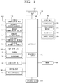
- FIG. 1 is a block diagram of a mobile terminal according to an embodiment of the present invention.
- the mobile terminal 100 includes a radio communication unit 110, an A/V (Audio/Video) input unit 120, a user input unit 130, a sensing unit 140, an output unit 150, a memory 160, an interface unit 170, a controller 180, and a power supply unit 190.
- FIG. 1 shows the mobile terminal 100 having various components, but it is understood that implementing all of the illustrated components is not a requirement. The mobile terminal 100 may be implemented by greater or fewer components.
- the radio communication unit 110 typically includes one or more components to authorize radio communication between the mobile terminal 100 and a radio communication unit system or a network in which the mobile terminal 100 is located.
- the radio communication unit 110 may include a broadcast receiving module 111, a mobile communication module 112, a wireless Internet module 113, a short range communication module 114, a location information module 115, etc.
- the broadcast receiving module 111 receives broadcast signals and/or broadcast associated information from an external broadcast management server (or other network entity) via a broadcast channel.
- the broadcast channel may include a satellite channel and/or a terrestrial channel.
- the broadcast management server may mean a server for generating broadcast signals and/or broadcast-related information and transmitting them to the mobile terminal, or a server for receiving generated broadcast signals and/or broadcast-related information and transmitting them to the mobile terminal.
- the broadcast signal may include a TV broadcast signal, a radio broadcast signal, a data broadcast signal, and the like. Also, the broadcast signal may further include a broadcast signal combined with a TV or radio broadcast signal.
- the broadcast associated information may also be provided via a mobile communication network and, in this case, the broadcast associated information may be received by the mobile communication module 112.
- the broadcast signal may exist in various forms. For example, it may exist in the form of an electronic program guide (EPG) of digital multimedia broadcasting (DMB), electronic service guide (ESG) of digital video broadcast-handheld (DVB-H), and the like.
- EPG electronic program guide
- DMB digital multimedia broadcasting
- ESG electronic service guide
- DVB-H digital video broadcast-handheld
- the broadcast receiving module 111 may be configured to receive signals broadcast by using various types of broadcast systems.
- the broadcast receiving module 111 may receive a digital broadcast by using a digital broadcast system such as multimedia broadcasting-terrestrial (DMB-T), digital multimedia broadcasting-satellite (DMB-S), digital video broadcast-handheld (DVB-H), the data broadcasting system known as media forward link only (MediaFLO®), integrated services digital broadcast-terrestrial (ISDB-T), etc.
- the broadcast receiving module 111 may be configured to be suitable for every broadcast system that provides a broadcast signal as well as the above-mentioned digital broadcast systems.
- Broadcasting signals and/or broadcasting associated information received through the broadcast receiving module 111 may be stored in the memory 160.
- the mobile communication module 112 transmits/receives wireless signals to/from at least one of network entities (e.g., base station, an external terminal, a server, etc.) on a mobile communication network.
- the wireless signals may include audio call signal, video call signal, or various formats of data according to transmission/reception of text/multimedia messages.
- the wireless internet module 113 supports wireless Internet access for the mobile terminal. This module may be internally or externally coupled to the mobile terminal 100. Examples of such wireless Internet access may include Wireless LAN (WLAN) (Wi-Fi), Wireless Broadband (Wibro), World Interoperability for Microwave Access (Wimax), High Speed Downlink Packet Access (HSDPA), and the like.
- WLAN Wireless LAN
- Wibro Wireless Broadband
- Wimax World Interoperability for Microwave Access
- HSDPA High Speed Downlink Packet Access
- the short-range communication module 114 denotes a module for short-range communications. Suitable technologies for implementing this module may include BLUETOOTH, Radio Frequency IDentification (RFID), Infrared Data Association (IrDA), Ultra-WideBand (UWB), ZigBee, and the like.
- RFID Radio Frequency IDentification
- IrDA Infrared Data Association
- UWB Ultra-WideBand
- ZigBee ZigBee
- the position information module 115 denotes a module for sensing or calculating a position of a mobile terminal.
- An example of the position information module 115 may include a Global Position System (GPS) module.
- GPS Global Position System
- the A/V input unit 120 is configured to receive an audio or video signal.
- the AN input unit 120 may include a camera 121, a microphone 122 or the like.
- the camera 121 processes image data of still pictures or video acquired by an image capture device in a video capturing mode or an image capturing mode.
- the processed image frames may be displayed on a display unit 151.
- the image frames processed by the camera 121 may be stored in the memory 160 or transmitted via the wireless communication unit 110.
- the camera 121 may be provided in two or more according to the configuration of the mobile terminal.
- the microphone 122 may receive sounds (audible data) via a microphone in a phone call mode, a recording mode, a voice recognition mode, and the like, and can process such sounds into audio data.
- the processed audio (voice) data may be converted for output into a format transmittable to a mobile communication base station via the mobile communication module 112 in case of the phone call mode.
- the microphone 122 may implement various types of noise canceling (or suppression) algorithms to cancel (or suppress) noise or interference generated in the course of receiving and transmitting audio signals.
- the user input unit 130 may generate key input data from commands entered by a user to control various operations of the mobile communication terminal.
- the user input unit 130 may include a keypad, a dome switch, a touch pad (e.g., a touch sensitive member that detects changes in resistance, pressure, capacitance, etc. due to being contacted) a jog wheel, a jog switch, and the like.
- the sensing unit 140 detects a current status (or state) of the mobile terminal 100 such as an opened or closed state of the mobile terminal 100, a location of the mobile terminal 100, the presence or absence of user contact with the mobile terminal 100, the orientation of the mobile terminal 100, an acceleration or deceleration movement and direction of the mobile terminal 100, etc., and generates commands or signals for controlling the operation of the mobile terminal 100.
- a current status or state
- the sensing unit 140 may sense whether the slide phone is open or closed.
- the sensing unit 140 can detect whether or not the power supply unit 190 supplies power or whether or not the interface unit 170 is coupled with an external device.
- the sensing unit 140 may include a proximity sensor 141.
- the output unit 150 is configured to provide outputs in a visual, audible, and/or tactile manner.
- the output unit 150 may include the display unit 151, an audio output module 152, an alarm unit 153, a haptic module 154, and the like.
- the display unit 151 may display information processed in the mobile terminal 100. For example, when the mobile terminal 100 is in a phone call mode, the display unit 151 may display a User Interface (Ul) or a Graphic User Interface (GUI) associated with a call or other communication (such as text messaging, multimedia file downloading, etc.). When the mobile terminal 100 is in a video call mode or image capturing mode, the display unit 151 may display a captured image and/or received image, a UI or GUI that shows videos or images and functions related thereto, and the like.
- Ul User Interface
- GUI Graphic User Interface
- the display unit 151 may include at least one of a Liquid Crystal Display (LCD), a Thin Film Transistor-LCD (TFT-LCD), an Organic Light Emitting Diode (OLED) display, a flexible display, a three-dimensional (3D) display, or the like.
- LCD Liquid Crystal Display
- TFT-LCD Thin Film Transistor-LCD
- OLED Organic Light Emitting Diode
- flexible display a three-dimensional (3D) display, or the like.
- Some of these displays may be configured to be transparent so that outside may be seen therethrough, which may be referred to as a transparent display.
- a representative example of the transparent display may include a Transparent Organic Light Emitting Diode (TOLED), and the like.
- the rear surface portion of the display unit 151 may also be implemented to be optically transparent. Under this configuration, a user can view an object positioned at a rear side of a body through a region occupied by the display unit 151 of the body.
- the display unit 151 may be implemented in two or more in number according to a configured aspect of the mobile terminal 100. For instance, a plurality of displays may be arranged on one surface integrally or separately, or may be arranged on different surfaces.
- the display unit 151 and a touch sensitive sensor have a layered structure therebetween, the structure may be referred to as a touch screen.
- the display unit 151 may be used as an input device rather than an output device.
- the touch sensor may be implemented as a touch film, a touch sheet, a touch pad, and the like.
- the touch sensor may be configured to convert changes of a pressure applied to a prescribed part of the display unit 151, or a capacitance occurring from a prescribed part of the display unit 151, into electric input signals. Also, the touch sensor may be configured to sense not only a touched position and a touched area, but also a touch pressure.
- touch controller When touch inputs are sensed by the touch sensors, corresponding signals are transmitted to a touch controller (not shown).
- the touch controller processes the received signals, and then transmits corresponding data to the controller 180. Accordingly, the controller 180 may sense which region of the display unit 151 has been touched.
- a proximity sensor 141 may be arranged at an inner region of the mobile terminal blocked by the touch screen, or near the touch screen.
- the proximity sensor 141 indicates a sensor to sense presence or absence of an object approaching to a surface to be sensed, or an object disposed near a surface to be sensed, by using an electromagnetic field or infrared rays without a mechanical contact.
- the proximity sensor 141 has a longer lifespan and a more enhanced utility than a contact sensor.
- the proximity sensor 141 may include a transmissive type photoelectric sensor, a direct reflective type photoelectric sensor, a mirror reflective type photoelectric sensor, a high-frequency oscillation proximity sensor, a capacitance type proximity sensor, a magnetic type proximity sensor, an infrared rays proximity sensor, and so on.
- a capacitance type proximity sensor When the touch screen is implemented as a capacitance type, proximity of a pointer to the touch screen is sensed by changes of an electromagnetic field.
- the touch screen may be categorized into a proximity sensor.
- a status that the pointer is positioned to be proximate onto the touch screen without contact will be referred to as 'proximity touch'
- a status that the pointer substantially comes in contact with the touch screen will be referred to as 'contact touch'.
- 'proximity touch' a status that the pointer substantially comes in contact with the touch screen.
- the proximity sensor 141 senses proximity touch, and proximity touch patterns (e.g., distance, direction, speed, time, position, moving status, etc.). Information relating to the sensed proximity touch and the sensed proximity touch patterns may be output onto the touch screen.
- proximity touch patterns e.g., distance, direction, speed, time, position, moving status, etc.
- An illumination sensor, a gyro sensor, etc. as well as the proximity sensor may be provided at the mobile terminal.
- the illumination sensor is configured to measure the amount of peripheral light
- the gyro sensor (called 'acceleration sensor') is configured to measure a moving speed and a position of the mobile terminal.
- the audio output module 152 may convert and output as sound audio data received from the wireless communication unit 110 or stored in the memory 160 in a call signal reception mode, a call mode, a record mode, a voice recognition mode, a broadcast reception mode, and the like. Also, the audio output module 152 may provide audible outputs related to a particular function performed by the mobile terminal 100 (e.g., a call signal reception sound, a message reception sound, etc.). The audio output module 152 may include a speaker, a buzzer, and so on.
- the alarm unit 153 may provide outputs to inform about the occurrence of an event of the mobile terminal 100. Typical events may include call reception, message reception, key signal inputs, a touch input, etc. In addition to audio or video outputs, the alarm unit 153 may provide outputs in a different manner to inform about the occurrence of an event.
- the video signal or the audio signal may be output via the display unit 151 or the audio output module 152. Accordingly, the display unit 151 or the audio output module 152 may be classified as part of the alarm unit 153.
- the haptic module 154 generates various tactile effects which a user can feel.
- a representative example of the tactile effects generated by the haptic module 154 includes vibration.
- Vibration generated by the haptic module 154 may have a controllable intensity, a controllable pattern, and so on. For instance, different vibration may be output in a synthesized manner or in a sequential manner.
- the haptic module 154 may generate various tactile effects, including not only vibration, but also arrangement of pins vertically moving with respect to a skin being touched (contacted), air injection force or air suction force through an injection hole or a suction hole, touch by a skin surface, presence or absence of contact with an electrode, effects by stimulus such as an electrostatic force, reproduction of cold or hot feeling using a heat absorbing device or a heat emitting device, and the like.
- the haptic module 154 may be configured to transmit tactile effects (signals) through a user's direct contact, or a user's muscular sense using a finger or a hand.
- the haptic module 154 may be implemented in two or more in number according to the configuration of the mobile terminal 100.
- the memory 160 may store a program for the processing and control of the controller 180. Alternatively, the memory 160 may temporarily store input/output data (e.g., phonebook data, messages, still images, video and the like). Also, the memory 160 may store data relating to various patterns of vibrations and audio output upon the touch input on the touch screen.
- input/output data e.g., phonebook data, messages, still images, video and the like.
- the memory 160 may store data relating to various patterns of vibrations and audio output upon the touch input on the touch screen.
- the memory 160 may be implemented using any type of suitable storage medium including a flash memory type, a hard disk type, a multimedia card micro type, a memory card type (e.g., SD or DX memory), Random Access Memory (RAM), Static Random Access Memory (SRAM), Read-Only Memory (ROM), Electrically Erasable Programmable Read-only Memory (EEPROM), Programmable Read-only Memory (PROM), magnetic memory, magnetic disk, optical disk, and the like.
- the mobile terminal 100 may operate a web storage which performs the storage function of the memory 160 on the Internet.
- the interface unit 170 may generally be implemented to interface the mobile terminal with external devices.
- the interface unit 170 may allow a data reception from an external device, a power delivery to each component in the mobile terminal 100, or a data transmission from the mobile terminal 100 to an external device.
- the interface unit 170 may include, for example, wired/wireless headset ports, external charger ports, wired/wireless data ports, memory card ports, ports for coupling devices having an identification module, audio Input/Output (I/O) ports, video I/O ports, earphone ports, and the like.
- I/O audio Input/Output
- the identification module may be configured as a chip for storing various information required to authenticate an authority to use the mobile terminal 100, which may include a User Identity Module (UIM), a Subscriber Identity Module (SIM), a Universal Subscriber Identity Module (USIM), and the like.
- the device having the identification module (hereinafter, referred to as 'identification device') may be implemented in a type of smart card. Hence, the identification device can be coupled to the mobile terminal 100 via a port.
- the interface unit 170 may serve as a path for power to be supplied from an external cradle to the mobile terminal 100 when the mobile terminal 100 is connected to the external cradle or as a path for transferring various command signals inputted from the cradle by a user to the mobile terminal 100.
- Such various command signals or power inputted from the cradle may operate as signals for recognizing that the mobile terminal 100 has accurately been mounted to the cradle.
- the controller 180 typically controls the overall operations of the mobile terminal 100. For example, the controller 180 performs the control and processing associated with telephony calls, data communications, video calls, and the like.
- the controller 180 may include a multimedia module 181 which provides multimedia playback.
- the multimedia module 181 may be configured as part of the controller 180 or as a separate component.
- the controller 180 can perform a pattern recognition processing so as to recognize writing or drawing input on the touch screen as text or image.
- the power supply unit 190 serves to supply power to each component by receiving external power or internal power under control of the controller 180.
- the embodiments described herein may be implemented within one or more of Application Specific Integrated Circuits (ASICs), Digital Signal Processors (DSPs), Digital Signal Processing Devices (DSPDs), Programmable Logic Devices (PLDs), Field Programmable Gate Arrays (FPGAs), processors, controllers, micro-controllers, micro processors, other electronic units designed to perform the functions described herein, or a selective combination thereof. In some cases, such embodiments are implemented by the controller 180.
- ASICs Application Specific Integrated Circuits
- DSPs Digital Signal Processors
- DSPDs Digital Signal Processing Devices
- PLDs Programmable Logic Devices
- FPGAs Field Programmable Gate Arrays
- processors controllers, micro-controllers, micro processors, other electronic units designed to perform the functions described herein, or a selective combination thereof.
- controller 180 such embodiments are implemented by the controller 180.
- the embodiments such as procedures and functions may be implemented together with separate software modules each of which performs at least one of functions and operations.
- the software codes can be implemented with a software application written in any suitable programming language. Also, the software codes may be stored in the memory 160 and executed by the controller 180.
- the display unit 151 will be explained in more detail.
- the display unit 151 is formed on the side surfaces as well as on the front surface. Under such configuration, the display unit can have a larger screen. That is, the present invention provides a mobile terminal having a front display and a side display, and a new type of user interface using the same.
- the front display, the side display, and operations implemented by the displays will be explained in more detail with reference to the attached drawings.
- FIG. 2 is a conceptual view illustrating an operation implemented by the mobile terminal of the present invention.
- a display unit 251 is provided with a first region 252 arranged on the front surface of the body, and a second region 253 extending from the first region 252 and arranged on the side surfaces of the body (wherein the side surface may be defined as a surface of the mobile terminal viewed from a lateral direction).
- the first region 252 and the second region 253 display different types of information, and are provided with different types of user graphic interfaces (GUI).
- GUI user graphic interfaces
- the second region 253 is provided with a left region 253a disposed on a left side surface of the mobile terminal, and a right region 253b disposed on a right side surface of the mobile terminal. Under such configuration, the second region 253 has a symmetric structure in right and left directions based on the first region 252.
- a home screen page may be output to the display unit 251 of the mobile terminal.
- the home screen page may include at least one object.
- the object may be an icon or a widget of an application installed at the mobile terminal.
- the home screen page may be output to an entire region of the display unit 251 including the first region 252 and the second region 253.
- the controller If an event occurs from at least one application, the controller outputs, to the second region 253, a notification icon 261 informing the event.
- the home screen page being output to the display unit 251 is merely exemplary, and a graphic user interface (GUI) of an application being currently executed is output to the display unit 251. In this state, the event may occur.
- GUI graphic user interface
- the display unit 251 may be provided with a touch sensor for sensing a touch input, so that a touch input to the notification icon can be sensed.
- the display unit 251 may output visual information implemented in the form of an image, a text, an icon, etc. And the display unit 251 may be converted into a deactivated state, by input of a specific control command or as time passes.
- the notification icon 261 may be output to at least one of the left region 253a and the right region 253b. In this embodiment, the notification icon 261 is disposed at the left region 253a.
- the notification icon 261, which is a bar type image long-formed along the side surface of the mobile terminal, may be displayed close to an upper end of the left region 253a.
- the controller displays information on the event on the first region 252.
- the notification icon 261 indicates an incoming message. If a user applies a drag input to the notification icon 261, the controller outputs information on the event, to the first region 252.
- the event-related information is at least part of a message, which may be output in the form of a preview.
- An image 262, of which size is gradually changed according to a path of the drag input, is generated at the first region 252. At least part of a message is displayed within the image 262. That is, information may be provided as the image 262 is unfolded according to a drag input, and content of a message to be output gradually appears. More specifically, the image may have an effect that folded paper becomes unfolded according to a drag input. The notification icon may move in association with the drag input.
- the event-related information disappears from the display unit 251. For instance, if a user's hand which is performing a drag input is detached from the display unit 251, the image 262 gradually disappears with moving to the left region. Under such configuration, information can be displayed for check of content, and then the information can disappear to be stored in the mobile terminal. This can allow a simple user interface to be implemented.
- the mobile terminal may provide information to a user in a novel manner, by controlling the side display.
- FIG. 3A is a front perspective view illustrating an embodiment of a mobile terminal according to the present invention
- FIG. 3B is a rear perspective view of the mobile terminal of FIG. 3A .
- the mobile terminal 200 according to the present invention is a bar type mobile terminal.
- the present invention is not limited to this, but may be applied to a slide type in which two or more bodies are coupled to each other so as to perform a relative motion, a folder type, or a swing type, a swivel type and the like.
- a body of the mobile terminal 200 comprises a case (casing, housing, cover, etc.).
- the case may be divided into a front case 201 and a rear case 202 (refer to FIGS. 3a and 3b ).
- a space formed by the front case 201 and the rear case 202 may accommodate various components therein.
- At least one intermediate case may further be disposed between the front case 201 and the rear case 202.
- Such cases may be formed by injection-molded synthetic resin, or may be formed using a metallic material such as stainless steel (STS) or titanium (Ti).
- STS stainless steel
- Ti titanium
- a display unit 251, an audio output module 252, a camera module 221, etc. may be disposed at the front body, mainly at the front case 201.
- An interface 270, etc. may be disposed on side surfaces of the front case 201 and the rear case 202.
- the display unit 251 occupies most of a main surface of the front case 201. That is, the display unit 251 is disposed on the front surface of the mobile terminal, and is configured to display visual information. In the present invention, the display unit 251 is formed on the side surfaces as well as on the front surface. More specifically, the display unit 251 is provided with a first region 252 arranged on the front surface of the body, and a second region 253 extending from the first region 252 and arranged on the side surfaces of the body.
- a window arranged on an upper surface of the display unit 251 has its two side surfaces bent. Under such configuration, the appearance of the front surface and the side surfaces of the body is determined by the window.
- the first region 252 and the second region 253 may be connected to each other without a boundary therebetween.
- the display unit 251 may be provided with a display bent and mounted in the mobile terminal in correspondence to the window.
- the display unit 251 may be a flexible display.
- the flexible display includes a display bent, twisted, folded and rolled up by an external force.
- the flexible display may include a general flexible display and electronic paper.
- the general flexible display indicate a light-weighted and unbreakable display fabricated on a thin and flexible substrate which can be bent or folded like paper, while maintaining characteristics of the conventional flat display.
- Electronic paper is a display technique using characteristics of general ink, which may be different from a general flat display in that reflected light is used.
- the electronic paper may change images or texts by twisting balls, or an electrophoresis using capsules.
- the body where two side surfaces of the display unit are bent, can be implemented by the flexible characteristics.
- the audio output unit 252 and the camera module 221 may be disposed at a region adjacent to one end of the display unit 251, and a front user input unit (not shown) and a microphone 222 may be disposed at a region adjacent to another end of the display unit 251.
- the front user input unit may include a plurality of manipulation units.
- the manipulation units may be referred to as manipulating portions, and may include any type of manipulation units that can be manipulated by a user in a tactile manner.
- the display unit 251 may form a touch screen together with a touch sensor.
- the touch screen may be implemented as a user input unit.
- a front user input unit may not be provided on the front surface of the mobile terminal.
- the mobile terminal may be configured so that an input to the body can be performed only through the display unit 251 and a rear user input unit 232 to be explained later.
- a camera module 221' may be additionally provided on the rear case 202.
- the camera module 221' faces a direction which is opposite to a direction faced by the camera module 221 (refer to FIG. 3a ), and may have different pixels from those of the camera module 221.
- the camera module 221 may operate with relatively lower pixels (lower resolution).
- the camera module 221 may be useful when a user can capture his face and send it to another party during a video call or the like.
- the camera module 221' may operate with a relatively higher pixels (higher resolution) such that it can be useful for a user to obtain higher quality pictures for later use.
- the camera modules 221 and 221' may be installed at the body so as to rotate or pop-up.
- a flash and a mirror may be additionally disposed close to the camera module 221'.
- the flash operates in conjunction with the camera module 221' when taking a picture using the camera module 221'.
- the mirror can cooperate with the camera module 221' to allow a user to photograph himself in a self-portrait mode.
- An audio output unit may be additionally arranged on a rear surface of the body.
- the audio output unit disposed on the rear surface of the body may implement a stereo function, together with the audio output unit 252 (refer to FIG. 3a ) disposed on the front surface of the body.
- the audio output unit disposed on the rear surface of the body may be configured to operate as a speakerphone during a call.
- a first audio output unit 252 configured as a receiver may be formed on the front surface, and a second audio output unit configured as a speaker may be formed on the rear surface.
- the present invention is not limited to this. That is, the second audio output unit may be provided on a side surface of the mobile terminal.
- a power supply unit 290 for supplying power to the mobile terminal 200 is mounted to the body.
- the power supply unit 290 may be mounted in the body, or may be detachably mounted to the body.
- a rear user input unit 232 may be disposed on the rear surface of the body.
- the rear user input unit 232 may be disposed below the camera module 221'.
- the rear user input unit 232 is manipulated to input various commands for controlling the operation of the mobile terminal 200.
- the rear user input unit 232 is configured to input commands such as POWER ON/OFF, START, END and SCROLL, commands for controlling a level of sound outputted from the audio output module 252, or commands for converting the current mode of the display unit 251 to a touch recognition mode.
- commands such as POWER ON/OFF, START, END and SCROLL, commands for controlling a level of sound outputted from the audio output module 252, or commands for converting the current mode of the display unit 251 to a touch recognition mode.
- the present invention is not limited to this. That is, the mobile terminal may be provided with only one of the front user input unit and the rear user input unit 232.
- the controller 180 can generate a control signal related to an event generated from an application, using the side surfaces of the display unit.
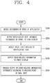
- FIG. 4 is a flowchart illustrating a method for controlling a mobile terminal according to the present invention.
- the controller detects that an event has occurred from at least one application (S100).
- the application means all types of programs which can operate in the mobile terminal, which comprises a concept of a widget, a home launcher, etc. Therefore, the application may be a program which performs web browsing, reproduction of moving images, transmission/reception of messages, schedule management and application update.
- An event may occur in a case where there is a missed call, there is an application to be updated, there is an incoming message, a charging operation is performed, power of the mobile terminal is turned on or off, or an LCD awake key is pressed (LCD awake key).
- the event may be an alarm, an Incoming call, a missed notification, etc.
- the controller senses the occurrence of the event.
- an event occurs.
- the controller outputs a notification icon indicating occurrence of an event, to the side surfaces of the display unit (S200).
- the display unit of the mobile terminal may be divided into a first region arranged on the front surface of the body, and a second region extending from the first region and arranged on the side surfaces of the body.
- the side display corresponds to the second region.
- the second region is provided with a left region and a right region disposed on a left side surface and a right side surface of the mobile terminal, respectively.
- the notification icon is output to at least one of the left region and the right region.
- the notification icon 261 may be a bar type image displayed along the side surface of the mobile terminal, and may include different images according to a type of an event-occurred application. As another example, the notification icon 261 may include different images according to an event type, or according to the amount of event-related information. The different images indicate images different from each other in shape, length, color, etc.
- the controller senses a touch input applied to the notification icon 261 (S300).
- the second region is configured as a touch screen.
- the controller In response to the touch input, the controller outputs information related to the event to the front display (first region) (S400).
- the event may be reception of messages, and the information may be content of a message.
- the event may be a notification of a schedule set in a schedule management application, and the information may be detailed information of a set schedule.
- the event may be occurrence of an application to be updated, and the information may be detailed information of an application to be updated.
- a different control may be performed according to a type of the touch input. For instance, if a short-touch input is applied to the notification icon, a message may be updated. On the other hand, if a long-touch input is applied to the notification icon, the notification icon may be deleted. In this embodiment, if a drag input is applied to the notification icon, the event-related information is displayed on the first region.
- the controller processes output of the event-related information differently according to a release point of a drag input (S500).
- an image of which size is gradually changed according to a path of the drag input, is generated at the first region.
- the information is displayed within the image.
- the image is differently processed according to a release point of the drag input.
- the image may be a status bar, or a screen for executing a specific function (e.g., connection of a call signal).
- the image and the information may disappear from the display unit.
- the drag input is released on the right region after being connected to the right region from the left region, the image and the information are continuously output.
- a new control command may be performed according to a touch input.
- information to be output may be changed according to a flicking input applied to the image.
- the information to be output may correspond to events which have occurred sequentially, respectively.
- the method for controlling a mobile terminal according to the present invention may be embodied in various manners as shown in FIGS. 5 to 13 .
- components having the same or similar configuration as/to those of the aforementioned embodiment will be provided with the same or similar reference numerals, and explanations thereof will be omitted.
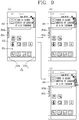
- FIGS. 5 to 9 are conceptual views illustrating operations implemented by the mobile terminal of FIG. 3A , in which a status bar is controlled using a touch input applied to a side display.
- notification icons may be generated in the order of occurrence of events, and may disappear after being checked by a user.
- notification icons informing the occurrence of the events are sequentially output in the order of occurrence of events.
- a first notification icon 261a, a second notification icon 261b and a third notification icon 261c are arranged in a lengthwise direction of the mobile terminal.
- each notification icon may be an icon which represents a category.
- the first notification icon 261a may be an icon corresponding to a category related to message reception
- the second notification icon 261b may be an icon corresponding to a category related to schedule management
- the third notification icon 261c may be an icon corresponding to a category related to application update. As messages are assorted by category, a user can view notifications of only desired applications at one time.
- the first notification icon 261a indicating an incoming message is output to the second region 253.
- the second notification icon 261b and the third notification icon 261c move downward in a lengthwise direction of the mobile terminal. That is, the notification icon disposed on the uppermost side of the mobile terminal informs a recently-occurred event.
- the present invention is not limited to this.
- the first notification icon 261a, the second notification icon 261b and the third notification icon 261c may be output to preset positions in the order of occurrence of events.
- the image 262 may be a status bar.
- Positions of the second notification icon 261b and the third notification icon 261c are determined as the second notification icon 261b associated with the recent icon moves toward the uppermost side of the mobile terminal. That is, the second notification icon 261b is arranged on the uppermost side of the mobile terminal, and the third notification icon 261c is arranged below the second notification icon 261b.
- event-related information may not disappear but may be continuously output to the screen.
- a boundary of the image is fixed to said another region.
- information displayed within the image is controlled using a touch input applied to the image.
- the notification icon in a state where the notification icon has been output (refer to FIG. 6 (a) ), if a drag input is connected from the left region 253a to the right region 253b and then is released on the right region 253b as shown in FIG. 6 (b) and (c) , output of an image and information (message content in the status bar in this embodiment) is maintained. That is, the status bar covers a display region between the left region 253a and the right region 253b in a widthwise direction of the mobile terminal. And the notification icon 261 moves from the left region 253a to the right region 253b to thus be positioned on the right region 253b.
- a sticker function by which a user can use a related application in a state where the status bar is fixed, can be implemented.
- the sticker function may be released by a drag input performed in another direction as shown in FIG. 6 (d) . For instance, if a user applies a drag input from the right region 253b to the left region 253a, the status bar moves toward the left region 253a to thus gradually disappear.
- the present invention is not limited to this.
- the sticker function may be released by other touch input, e.g., a consecutive touch input, etc.
- FIGS. 7 to 9 are conceptual views illustrating various examples of a sticker function.
- the image and the information are moved by a user's up-down drag applied to the notification icon.
- the image is moved by a drag input applied to the notification icon in a direction perpendicular to the drag input for unfolding the image.
- the rest notification icons move along the image.
- a point where the user's drag input is released is a final position of the image in upper and lower directions.
- a flicking input is applied up and down in a state where the status bar has been fixed to the screen, a full message can be checked in a scrolling manner.
- the image 262 for outputting the first message is changed into an image 264 for outputting a second message.
- a scroll bar may be created, or the length of an image may be controlled by a drag input.
- the length of the notification icon may be variable according to the amount of the event-related information.
- a scroll bar for moving the displayed information up and down may be generated on at least part of the second region 253.
- FIG. 7 (b) after an image is moved up and down, a flicking input is performed.
- the present invention is not limited to this.
- the operation to move an image up and down shown in FIG. 7 (b) can be deleted in this embodiment.
- the operation to move an image up and down, the scrolling, etc. may be a control operation added to the aforementioned embodiment or the following embodiment.
- a scrolling operation in right and left directions can be performed.
- received messages may be output sequentially.
- a user can check previous messages.
- the image 264 for outputting the second message may be changed into an image 265 for outputting a third message has been output.
- a lower screen can be utilized when a sticker function is executed.
- the first region 252 is divided into a first part and a second part.
- Information on the event is displayed on the first part, and a screen output to the first region 252 before the touch input is applied is continuously displayed on the second part.
- an application different from an event-occurred application is driven in a state where the event-related information is displayed on the first part, an execution screen for the different application may be output to the second part.
- the controller senses a control command related to the information displayed on the first part, using a touch input applied to the second region 253.
- a lower screen is configured so that a touch input can be executed in a state where an image has been fixed. In this state, if a user touches an icon of an application on a home screen page, the application is executed.
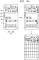
- FIG. 8A illustrates a case where a schedule management application is executed.
- a schedule management application As a schedule management application is executed, an execution screen is output to the lower screen in a state where an image has been fixed. More specifically, in a case where a schedule is included in message content, if a user touches an icon of a schedule management application for driving, the schedule can be input to the execution screen.
- the image is a transparent image, and the execution screen is overlapped with the image. Even if part of the execution screen for the schedule management application is viewed, a touch input with respect to the image may be defined as a control command with respect to the image.
- a result of a control command with respect to the image may be used to control the execution screen.
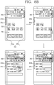
- a mobile banking is driven, and content may be input to an execution screen of an application based on information output to the image. More specifically, at least part of output information may be copied by a user's touch input. For instance, if a user applies a long-touch input to an output text or number, the text or number is copied. Then, if the user applies a long-touch input to an execution screen, a paste function is performed. The long-touch input may be performed on an activated part of the execution screen.
- a copy-paste function can be performed between the status bar and the main screen. Further, in a case where a user performs other operation with viewing a message, the current application needs not be converted, and a text, an image, etc. of the status bar can be immediately moved to the execution screen of the application.
- FIG. 9 is a view showing another control method of a mobile terminal, in which messages are managed at one time by category.
- a mark 'X' is generated. If the mark 'X' is touched, a specific message is deleted. More specifically, when an image is fixed to the screen, a specific icon is generated. If a touch input is applied to the specific icon, a corresponding message is deleted. In this case, the image is continuously fixed to the screen, and the next message is output.
- a deletion command may be a double tap on the right region 253b, or a touch input to a specific icon.
- FIGS. 10 to 13 are conceptual views illustrating various embodiments related to reception of information.
- FIG. 10 is a conceptual view illustrating a driving of a side display when a call signal is received.
- FIG. 10 if a call signal is received while an application is driven, information on the call signal is displayed on the second region 253. More specifically, referring to FIG. 10 (a) , if an application related to reproduction of moving images is executed, an execution screen related to reproduction of moving images is output to the first region 252 and the second region 253.
- an indicator 263 informing reception of the call signal is output to the second region 253 as shown in FIG. 10 (b) .
- the indicator 263 may be information on another party's mobile terminal which has transmitted the call signal, e.g., a phone number or another party's name.
- the indicator 263 moves within the second region 253 while the call signal is received, and disappears when a notification icon is generated.
- information on another party's mobile terminal is displayed on the second region 253 in a scrolling manner.
- the information on another party's mobile terminal may be displayed with moving toward a lower side from an upper side of the screen, or toward an upper side from a lower side of the screen.
- the display by scrolling may be consecutive from the left region 253a to the right region 253b.
- information on another party's mobile terminal may be scrolled on the left region 253a, toward a lower side from an upper side of the screen.
- the information may be scrolled on the right region 253b, toward an upper side from a lower side of the screen.
- a notification icon 261 informing a missed call is output to the second region 253. Under such configuration, the user can recognize a missed call.
- a status bar may be output to the first region 252 like in the aforementioned embodiment, and information on another party's mobile terminal may be output to the status bar.
- the controller performs a control related to an incoming call.
- a control command instructing a connection refusal i.e., call disconnection
- Information is output to the second region 253, and a call connection or a call disconnection is performed according to a direction of a touch input applied to the second region 253.
- the user can check the incoming call through a side display.
- the user can perform a call connection or a call disconnection through flicking in or flicking out.
- a call refusal (call disconnection) may be easily performed. This will be explained in more detail with reference to FIG. 12 .
- the display unit is operated differently according to whether the mobile terminal is in a first state, a second state or a third state.
- the first state indicates a state where the front surface of the mobile terminal is toward the upper side
- the second state indicates a state where the rear surface of the mobile terminal is toward the upper side
- the third state indicates a state where the body of the mobile terminal is covered by an additional case (pouch), etc.
- the determination, on whether the mobile terminal is in the first state, the second state or the third state, may be performed through combination of at least two of a proximity sensor, an illumination sensor and a gyro sensor.
- FIG. 12 shows operations of the mobile terminal in the second state and the third state.
- the deactivated state of the display unit is maintained.
- the indicator 263 informing reception of the call signal is output to the second region 253.
- the indicator may be information on another party's mobile terminal, or lighting information. Under such configuration, if there is an incoming call in a state where the mobile terminal is turned inside out, a user can check the incoming call through a side display.
- a control command instructing a connection refusal (call disconnection) is input.
- the touch input may be a long-touch input, a short-touch input, a flicking input, a drag input, etc.
- a control command instructing a call connection or a call refusal may be performed according to a direction of the drag input.
- FIG. 13 is a conceptual view illustrating such function.
- the controller senses the covered state. If information 266 is received through the wireless communication unit under such state, at least part of the received information 266 is output to the second region 253. If a control command has not been input by a user, the received information 266 disappears and a notification icon 261 is output like in the aforementioned embodiment.
- the controller may display the received information on the first region 252. For instance, if the pouch is open in a state where the second region 253 has been touched, the mobile terminal senses the open state to thus display the received information on the first region 252.
- the controller upon detection of touch inputs consecutively applied to the second region 253 with time intervals, the controller updates information output to the second region 253.
- information such as a news and a weather is output to a side display, and the information is updated to recent information whenever the side display is tapped. That is, widgets such as a news and a weather, which need to be updated periodically, are displayed on the side surfaces. If the side surfaces are tapped for update, new information can be displayed without influencing on the main screen.
- the present invention can have the following advantages.
- a new type of user interface can be provided.
- information on an occurred event can be provided in various manners, even in a deactivated state of the front display.
Landscapes
- Engineering & Computer Science (AREA)
- Theoretical Computer Science (AREA)
- General Engineering & Computer Science (AREA)
- Human Computer Interaction (AREA)
- Physics & Mathematics (AREA)
- General Physics & Mathematics (AREA)
- Signal Processing (AREA)
- Computer Networks & Wireless Communication (AREA)
- Computer Hardware Design (AREA)
- Environmental & Geological Engineering (AREA)
- Telephone Function (AREA)
- User Interface Of Digital Computer (AREA)
- Controls And Circuits For Display Device (AREA)
Claims (22)
- Mobiles Endgerät, umfassend:eine drahtlose Kommunikationseinheit, die dazu eingerichtet ist, drahtlose Kommunikation bereitzustellen; undeinen Berührungsbildschirm mit einer Vorderfläche und gekrümmten Flächen, die sich von der Vorderfläche des Berührungsbildschirms erstrecken,wobei die Vorderfläche und die gekrümmten Flächen durchgehend sind, undwobei die gekrümmten Flächen eine linke gekrümmte Fläche und eine rechte gekrümmte Fläche an beiden Seiten des Berührungsbildschirms umfassen,wobei das mobile Endgerät ferner eine Steuereinheit umfasst, die eingerichtet ist zum:Anzeigen einer Startbildschirmseite, die ein Symbol einer ersten Anwendung umfasst, auf der Vorderfläche und den gekrümmten Flächen des Berührungsbildschirms,Anzeigen eines ersten Benachrichtigungssymbols an einer ersten Stelle auf einer der linken gekrümmten Fläche und der rechten gekrümmten Fläche des Berührungsbildschirms als Reaktion auf ein erstes Ereignis, das mit einer zweiten Anwendung zusammenhängt,Anzeigen eines ersten Bilds, das eine Information umfasst, die mit dem ersten Ereignis zusammenhängt, auf dem Berührungsbildschirm als Reaktion auf ein erstes Berühren und Ziehen von dem ersten Benachrichtigungssymbol auf der einen der linken gekrümmten Fläche und der rechten gekrümmten Fläche zu der Vorderfläche des Berührungsbildschirms,dadurch gekennzeichnet, dass das erste Bild auf der gekrümmten Fläche und der Vorderfläche des Berührungsbildschirms an einer Stelle angezeigt wird, die dem ersten Benachrichtigungssymbols auf der einen der linken gekrümmten Fläche und der rechten gekrümmten Fläche entspricht,wobei das erste Bild an der Vorderfläche des Berührungsbildschirms erzeugt wird, während das erste Berühren und Ziehen sich auf einem Pfad von der einen der linken gekrümmten Fläche und der rechten gekrümmten Fläche zu der Vorderfläche des Berührungsbildschirms bewegt,wobei eine Größe des ersten Bilds gemäß dem Pfad des ersten Berührens und Ziehens fortschreitend geändert wird,wobei das erste Bild mit der Startbildschirmseite, die das Symbol der ersten Anwendung umfasst, überlappt wird,wobei die Steuereinheit ferner dazu eingerichtet ist, die Verarbeitung des ersten Bilds auf der Basis eines Freigabepunkts des ersten Berührens und Ziehens zu variieren,wobei, wenn das erste Berühren und Ziehen innerhalb der Vorderfläche freigegeben wird, das erste Bild von dem Berührungsbildschirm verschwindet, undwobei,wenn das erste Berühren und Ziehen auf der anderen der linken gekrümmten Fläche und der rechten gekrümmten Fläche freigegeben wird, das erste Bild weiterhin in einem Zustand ausgegeben wird, in dem die Startbildschirmseite auf der Vorderfläche angezeigt wird, und,wenn das Symbol der ersten Anwendung, das von der Startbildschirmseite umfasst ist, in einem Zustand berührt wird, in dem das erste Bild weiterhin ausgegeben wird, ein Ausführungsbildschirm der ersten Anwendung angezeigt wird und mit dem ersten Bild überlappt wird, wobei das erste Bild als ein transparentes Bild angezeigt wird, so dass der Ausführungsbildschirm der ersten Anwendung sichtbar ist.
- Mobiles Endgerät nach Anspruch 1, wobei die Steuereinheit weiterhin eingerichtet ist zum:Anzeigen eines zweiten Benachrichtigungssymbols an einer zweiten Stelle, die sich von der ersten Stelle unterscheidet, auf der einen der linken gekrümmten Fläche und der rechten gekrümmten Fläche des Berührungsbildschirms als Reaktion auf ein zweites Ereignis, das mit einer dritten Anwendung zusammenhängt,Anzeigen eines zweiten Bilds, das eine Information umfasst, die mit dem zweiten Ereignis zusammenhängt, auf dem Berührungsbildschirm als Reaktion auf ein zweites Berühren und Ziehen von dem zweiten Benachrichtigungssymbol auf der einen der linken gekrümmten Fläche und der rechten gekrümmten Fläche zu der Vorderfläche des Berührungsbildschirms.
- Mobiles Endgerät nach einem der Ansprüche 1 bis 2, wobei die erste Stelle eine vorher festgelegte Stelle ist und die zweite Stelle eine vorher festgelegte Stelle ist.
- Mobiles Endgerät nach einem der Ansprüche 2 bis 3, wobei das erste und das zweite Benachrichtigungssymbol ein Bild vom Balkentyp sind, das auf der einen der linken gekrümmten Fläche und der rechten gekrümmten Fläche des Berührungsbildschirms angezeigt wird und sich entlang der einen der linken gekrümmten Fläche und der rechten gekrümmten Fläche des Berührungsbildschirms erstreckt.
- Mobiles Endgerät nach Anspruch 4, wobei das Bild vom Balkentyp eines von einer Mehrzahl von Bildern vom Balkentyp mit unterschiedlichen Farben ist.
- Mobiles Endgerät nach Anspruch 1, wobei die Steuereinheit ferner dazu eingerichtet ist, das erste Bild, das eine Information umfasst, die mit dem ersten Ereignis zusammenhängt, nur als Reaktion auf das erste Berühren und Ziehen anzuzeigen und das zweite Bild, das die Information umfasst, die mit dem zweiten Ereignis zusammenhängt, nur als Reaktion auf das zweite Berühren und Ziehen anzuzeigen.
- Mobiles Endgerät nach Anspruch 1, wobei das erste Benachrichtigungssymbol angezeigt wird, während der Startbildschirm angezeigt wird.
- Mobiles Endgerät nach Anspruch 2, wobei das erste Benachrichtigungssymbol und das zweite Benachrichtigungssymbol angezeigt werden, während der Startbildschirm angezeigt wird.
- Mobiles Endgerät nach Anspruch 1, wobei der Berührungsbildschirm ferner dazu eingerichtet ist, eine Statusinformation anzuzeigen, die ein oder mehrere Grafikobjekte umfasst, die mindestens eine restliche Batterielebensdauer, eine Signalstärke, eine aktuelle Zeit und ein Auftreten eines Ereignisses angeben.
- Mobiles Endgerät nach Anspruch 9, wobei der Berührungsbildschirm eine Länge aufweist, die länger als seine Breite ist, und
wobei das eine oder die mehreren Grafikobjekte entlang einer Breitenrichtung angezeigt werden und das erste und das zweite Benachrichtigungssymbol in einer Längenrichtung angeordnet sind. - Mobiles Endgerät nach Anspruch 1, wobei eine Länge des ersten Benachrichtigungssymbols gemäß einer Informationsmenge, die mit dem ersten Ereignis zusammenhängt, variabel ist.
- Mobiles Endgerät nach Anspruch 1, wobei die Steuereinheit ferner dazu eingerichtet ist, einen Scrollbalken, um die angezeigte Information zu scrollen, auf mindestens einem Teil der gekrümmten Fläche anzuzeigen, wenn die Information, die mit dem ersten Ereignis zusammenhängt, auf der Vorderfläche des Berührungsbildschirms angezeigt wird.
- Mobiles Endgerät nach Anspruch 1, wobei die Steuereinheit ferner eingerichtet ist zum:Anzeigen eines Indikators auf der gekrümmten Fläche als Reaktion auf ein Auftreten eines eingehenden Anrufs, wenn die Vorderfläche des Berührungsbildschirms abgedeckt ist, undeiner Information, die mit dem ersten Ereignis zusammenhängt, auf dem Berührungsbildschirm als Reaktion auf ein erstes Berühren und Ziehen von dem ersten Benachrichtigungssymbol auf der gekrümmten Fläche zu der Vorderfläche des Berührungsbildschirms.
- Mobiles Endgerät nach Anspruch 13, wobei der Indikator sich innerhalb der gekrümmten Fläche bewegt, während der eingehende Anruf empfangen wird.
- Mobiles Endgerät nach Anspruch 13, wobei der Indikator ein Licht umfasst.
- Mobiles Endgerät nach Anspruch 1, wobei das erste Ereignis und das zweite Ereignis mindestens einen bzw. eine von einem verpassten Anruf oder einer eingehenden Nachricht umfassen.
- Mobiles Endgerät nach Anspruch 16, wobei, wenn das erste Ereignis die eingehende Nachricht ist, die Information, die mit dem ersten Ereignis zusammenhängt und die auf der Vorderfläche des Berührungsbildschirms angezeigt wird, mindestens einen Teil der Nachricht umfasst.
- Mobiles Endgerät nach Anspruch 16, wobei, wenn das erste Ereignis der verpasste Anruf ist, die Information, die mit dem ersten Ereignis zusammenhängt und die auf der Vorderfläche des Berührungsbildschirms angezeigt wird, mindestens eine bzw. einen von einer Telefonnummer des Anrufers oder einem Namen des Anrufers umfasst.
- Mobiles Endgerät nach Anspruch 2, wobei das erste Benachrichtigungssymbol und das zweite Benachrichtigungssymbol unterschiedliche Bilder aufweisen, die unterschiedlichen Ereignisinformationen entsprechen.
- Mobiles Endgerät nach Anspruch 19, wobei jedes der unterschiedlichen Bilder in Bezug auf mindestens eine Form, Länge oder Farbe unterschiedlich ist.
- Mobiles Endgerät nach Anspruch 1, wobei das erste Bild und das zweite Bild eine Information zum Ausführen von mindestens einer bestimmten Funktion auf dem mobilen Endgerät umfassen.
- Verfahren zur Steuerung eines mobilen Endgeräts, das eine drahtlose Kommunikationseinheit, die dazu eingerichtet ist, drahtlose Kommunikation bereitzustellen, und einen Berührungsbildschirm mit einer Vorderfläche und gekrümmten Flächen, die sich von der Vorderfläche des Berührungsbildschirms erstrecken, umfasst,
wobei die Vorderfläche und die gekrümmten Flächen durchgehend sind und
wobei das Verfahren umfasst:Anzeigen einer Startbildschirmseite, die ein Symbol einer ersten Anwendung umfasst, auf der Vorderfläche und den gekrümmten Flächen des Berührungsbildschirms,Anzeigen eines ersten Benachrichtigungssymbols an einer ersten Stelle auf einer der linken gekrümmten Fläche und der rechten gekrümmten Fläche des Berührungsbildschirms als Reaktion auf ein erstes Ereignis, das mit einer zweiten Anwendung zusammenhängt,Anzeigen eines ersten Bilds, das eine Information umfasst, die mit dem ersten Ereignis zusammenhängt, auf dem Berührungsbildschirm als Reaktion auf ein erstes Berühren und Ziehen von dem ersten Benachrichtigungssymbol auf der einen der linken gekrümmten Fläche und der rechten gekrümmten Fläche zu der Vorderfläche des Berührungsbildschirms,dadurch gekennzeichnet, dass das erste Bild auf der gekrümmten Fläche und der Vorderfläche des Berührungsbildschirms an einer Stelle angezeigt wird, die dem ersten Benachrichtigungssymbol auf der einen der linken gekrümmten Fläche und der rechten gekrümmten Fläche entspricht,wobei das erste Bild an der Vorderfläche des Berührungsbildschirms erzeugt wird, während das erste Berühren und Ziehen sich auf einem Pfad von der einen der linken gekrümmten Fläche und der rechten gekrümmten Fläche zu der Vorderfläche des Berührungsbildschirms bewegt,wobei eine Größe des ersten Bilds gemäß dem Pfad des ersten Berührens und Ziehens fortschreitend geändert wird,wobei das erste Bild mit der Startbildschirmseite, die das Symbol der ersten Anwendung umfasst, überlappt wird,wobei die Steuereinheit weiterhin dazu eingerichtet ist, die Verarbeitung des ersten Bilds auf der Basis eines Freigabepunkts des ersten Berührens und Ziehens zu variieren,wobei, wenn das erste Berühren und Ziehen innerhalb der Vorderfläche freigegeben wird, das erste Bild von dem Berührungsbildschirm verschwindet, undwobei, wenn das erste Berühren und Ziehen auf der anderen der linken gekrümmten Fläche und der rechten gekrümmten Fläche freigegeben wird, das erste Bild weiterhin in einem Zustand ausgegeben wird, in dem die Startbildschirmseite auf der Vorderfläche angezeigt wird, und,wenn das Symbol der ersten Anwendung, das von der Startbildschirmseite umfasst ist, in einem Zustand berührt wird, in dem das erste Bild weiterhin ausgegeben wird, ein Ausführungsbildschirm der ersten Anwendung angezeigt wird und mit dem ersten Bild überlappt wird,wobei das erste Bild als ein transparentes Bild angezeigt wird, so dass der Ausführungsbildschirm der ersten Anwendung sichtbar ist.
Applications Claiming Priority (1)
| Application Number | Priority Date | Filing Date | Title |
|---|---|---|---|
| KR1020130086958A KR101504236B1 (ko) | 2013-07-23 | 2013-07-23 | 이동 단말기 |
Publications (2)
| Publication Number | Publication Date |
|---|---|
| EP2830293A1 EP2830293A1 (de) | 2015-01-28 |
| EP2830293B1 true EP2830293B1 (de) | 2019-07-03 |
Family
ID=50735826
Family Applications (1)
| Application Number | Title | Priority Date | Filing Date |
|---|---|---|---|
| EP14165122.4A Active EP2830293B1 (de) | 2013-07-23 | 2014-04-17 | Mobiles Endgerät mit zusätzlicher Anzeige auf der Seitenfläche |
Country Status (5)
| Country | Link |
|---|---|
| US (2) | US20150031417A1 (de) |
| EP (1) | EP2830293B1 (de) |
| KR (1) | KR101504236B1 (de) |
| CN (1) | CN104346097B (de) |
| DE (1) | DE202014010511U1 (de) |
Families Citing this family (78)
| Publication number | Priority date | Publication date | Assignee | Title |
|---|---|---|---|---|
| KR101515623B1 (ko) * | 2012-05-14 | 2015-04-28 | 삼성전자주식회사 | 벤디드 디스플레이를 갖는 휴대단말의 기능 운용 방법 및 장치 |
| TWD161258S (zh) * | 2013-01-03 | 2014-06-21 | 宏碁股份有限公司 | 螢幕之圖形化使用者介面 |
| USD744973S1 (en) * | 2013-06-14 | 2015-12-08 | Lg Electronics Inc. | Mobile phone |
| USD741281S1 (en) * | 2013-06-28 | 2015-10-20 | Lg Electronics Inc. | Mobile phone |
| JP1519345S (de) * | 2013-06-28 | 2015-03-16 | ||
| USD739368S1 (en) * | 2013-07-09 | 2015-09-22 | Samsung Display Co., Ltd. | Mobile phone |
| WO2015050345A1 (en) * | 2013-10-01 | 2015-04-09 | Lg Electronics Inc. | Control apparatus for mobile terminal and control method thereof |
| US9510251B2 (en) | 2013-12-31 | 2016-11-29 | Microsoft Technology Licensing, Llc | Call handoff initiation in hybrid networks |
| US9560185B2 (en) * | 2014-03-19 | 2017-01-31 | Microsoft Technology Licensing, Llc | Hybrid telecommunications network connection indicator |
| KR101659028B1 (ko) | 2014-06-17 | 2016-09-23 | 엘지전자 주식회사 | 이동 단말기 및 이의 제어 방법 |
| USD775597S1 (en) * | 2014-10-01 | 2017-01-03 | Samsung Electronics Co., Ltd. | Electronic device |
| KR102308645B1 (ko) * | 2014-12-29 | 2021-10-05 | 삼성전자주식회사 | 사용자 단말 장치 및 그의 제어 방법 |
| USD832230S1 (en) * | 2014-12-31 | 2018-10-30 | Samsung Electronics Co., Ltd. | Electronic device |
| USD784279S1 (en) * | 2014-12-31 | 2017-04-18 | Samsung Electronics Co., Ltd. | Electronic device |
| CN104571832A (zh) * | 2015-01-19 | 2015-04-29 | 三星电子(中国)研发中心 | 移动终端、及其操控系统和方法 |
| KR102252619B1 (ko) * | 2015-02-03 | 2021-05-17 | 삼성전자 주식회사 | 알림 제공 방법 및 이를 구현하는 전자 장치 |
| CN107407963A (zh) * | 2015-02-25 | 2017-11-28 | 意美森公司 | 用于与弯曲显示器的用户交互的系统和方法 |
| KR102113201B1 (ko) * | 2015-02-27 | 2020-05-20 | 삼성전자주식회사 | 기능 실행 방법 및 이를 지원하는 전자 장치 |
| KR101596848B1 (ko) * | 2015-03-02 | 2016-02-23 | 엘지전자 주식회사 | 디스플레이 패널 및 이동 단말기 |
| KR102326664B1 (ko) * | 2015-03-09 | 2021-11-17 | 삼성전자 주식회사 | 전자 기기 및 그의 통지 바 운용 방법 |
| CN106163168A (zh) * | 2015-04-22 | 2016-11-23 | 富泰华精密电子(郑州)有限公司 | 壳体及采用该壳体的电子装置 |
| KR102307303B1 (ko) * | 2015-05-20 | 2021-09-30 | 엘지전자 주식회사 | 이동단말기 및 그 제어방법 |
| KR102324866B1 (ko) | 2015-05-26 | 2021-11-12 | 엘지디스플레이 주식회사 | 백라이트유닛과 액정표시장치 및 이의 구동방법 |
| KR102378570B1 (ko) * | 2015-06-08 | 2022-03-25 | 삼성전자주식회사 | 휴대 장치 및 휴대 장치의 화면 변경방법 |
| KR20160147441A (ko) * | 2015-06-15 | 2016-12-23 | 엘지전자 주식회사 | 이동 단말기 및 그의 동작 방법 |
| KR102418901B1 (ko) * | 2015-06-16 | 2022-07-11 | 엘지전자 주식회사 | 와치 타입 단말기 및 그것의 제어 방법 |
| US20170010780A1 (en) * | 2015-07-06 | 2017-01-12 | Hand Held Products, Inc. | Programmable touchscreen zone for mobile devices |
| KR20170006557A (ko) * | 2015-07-08 | 2017-01-18 | 엘지전자 주식회사 | 이동 단말기 및 그 제어방법 |
| JP6129261B2 (ja) * | 2015-09-15 | 2017-05-17 | Line株式会社 | 通知制御方法、ユーザ端末装置及び通知制御プログラム |
| KR102543912B1 (ko) * | 2015-10-05 | 2023-06-15 | 삼성전자 주식회사 | 복수의 디스플레이를 구비한 전자장치 및 그 제어 방법 |
| KR102423447B1 (ko) | 2015-10-22 | 2022-07-21 | 삼성전자 주식회사 | 벤디드 디스플레이를 구비한 전자 장치 및 그 제어 방법 |
| KR20170054080A (ko) * | 2015-11-09 | 2017-05-17 | 삼성전자주식회사 | 전자장치 및 그의 동작 방법 |
| KR102427833B1 (ko) * | 2015-11-30 | 2022-08-02 | 삼성전자주식회사 | 사용자 단말장치 및 디스플레이 방법 |
| KR20170076489A (ko) * | 2015-12-24 | 2017-07-04 | 삼성전자주식회사 | 전자장치 및 그의 어플리케이션 프로그램 운용 방법 |
| US11717256B2 (en) | 2016-01-08 | 2023-08-08 | Siemens Medical Solutions Usa, Inc. | Motion independence in acoustic radiation force impulse imaging |
| KR102545907B1 (ko) * | 2016-02-18 | 2023-06-22 | 삼성전자주식회사 | 콘텐츠 표시 방법 및 이를 수행하는 전자 장치 |
| CN108700997B (zh) * | 2016-02-29 | 2021-07-27 | 夏普株式会社 | 显示控制装置、显示系统及显示控制方法 |
| CN107479810B (zh) * | 2016-06-07 | 2021-08-10 | 北京三星通信技术研究有限公司 | 基于辅助显示区域的操作方法及终端设备 |
| KR102545665B1 (ko) * | 2016-07-20 | 2023-06-21 | 삼성전자주식회사 | 알림 정보 표시 방법 및 장치 |
| CN107885445A (zh) * | 2016-09-29 | 2018-04-06 | 北京嘀嘀无限科技发展有限公司 | 隐藏区域的显示方法及装置 |
| KR102606119B1 (ko) * | 2016-12-05 | 2023-11-24 | 엘지전자 주식회사 | 단말기 및 그 제어 방법 |
| CN108205407B (zh) * | 2016-12-20 | 2021-07-06 | 夏普株式会社 | 显示装置、显示方法及存储介质 |
| JP6776113B2 (ja) * | 2016-12-20 | 2020-10-28 | シャープ株式会社 | 表示装置、表示装置における表示方法及びプログラム |
| KR102345883B1 (ko) | 2017-04-28 | 2022-01-03 | 삼성전자주식회사 | 그래픽 표시를 출력하는 전자 장치 |
| USD886814S1 (en) * | 2017-05-04 | 2020-06-09 | Lg Electronics Inc. | Television receiver |
| USD863122S1 (en) * | 2017-05-04 | 2019-10-15 | Lg Electronics Inc. | Television receiver |
| USD862302S1 (en) * | 2017-05-04 | 2019-10-08 | Lg Electronics Inc. | Television receiver |
| USD862304S1 (en) * | 2017-05-04 | 2019-10-08 | Lg Electronics Inc. | Television receiver |
| USD862296S1 (en) * | 2017-05-04 | 2019-10-08 | Lg Electronics Inc. | Television receiver |
| USD863121S1 (en) * | 2017-05-04 | 2019-10-15 | Lg Electronics Inc. | Television receiver |
| USD862303S1 (en) * | 2017-05-04 | 2019-10-08 | Lg Electronics Inc. | Television receiver |
| USD862298S1 (en) * | 2017-05-04 | 2019-10-08 | Lg Electronics Inc. | Television receiver |
| USD886815S1 (en) * | 2017-05-04 | 2020-06-09 | Lg Electronics Inc. | Television receiver |
| USD862301S1 (en) * | 2017-05-04 | 2019-10-08 | Lg Electronics Inc. | Television receiver |
| USD862295S1 (en) * | 2017-05-04 | 2019-10-08 | Lg Electronics Inc. | Television receiver |
| USD862300S1 (en) * | 2017-05-04 | 2019-10-08 | Lg Electronics Inc. | Television receiver |
| USD862297S1 (en) * | 2017-05-04 | 2019-10-08 | Lg Electronics Inc. | Television receiver |
| USD862299S1 (en) * | 2017-05-04 | 2019-10-08 | Lg Electronics Inc. | Television receiver |
| CN107688422B (zh) * | 2017-09-05 | 2020-06-26 | Oppo广东移动通信有限公司 | 通知消息显示方法及装置 |
| WO2019047189A1 (zh) * | 2017-09-08 | 2019-03-14 | 广东欧珀移动通信有限公司 | 消息显示方法、装置及终端 |
| CN107766022A (zh) * | 2017-10-19 | 2018-03-06 | 广东欧珀移动通信有限公司 | 一种画面显示方法、装置及存储介质 |
| CN108255378B (zh) * | 2018-02-09 | 2020-05-26 | 维沃移动通信有限公司 | 一种显示控制方法及移动终端 |
| CN109274828B (zh) * | 2018-09-30 | 2021-01-15 | 华为技术有限公司 | 一种生成截图的方法、控制方法及电子设备 |
| CN109215488B (zh) * | 2018-10-10 | 2023-09-22 | 孟欣艾 | 课程表 |
| US11550394B2 (en) | 2018-11-08 | 2023-01-10 | Goto Group, Inc. | Force-based control for a mobile device having a non-linear surface |
| CN110471639B (zh) * | 2019-07-23 | 2022-10-18 | 华为技术有限公司 | 显示方法及相关装置 |
| US12248340B2 (en) * | 2019-08-16 | 2025-03-11 | Sony Group Corporation | Information processing apparatus, information processing method, and information processing program |
| USD976225S1 (en) * | 2019-09-24 | 2023-01-24 | Beijing Xiaomi Mobile Software Co., Ltd. | Mobile phone with graphical user interface |
| USD947805S1 (en) * | 2019-09-24 | 2022-04-05 | Beijing Xiaomi Mobile Software Co., Ltd. | Mobile phone with graphical user interface |
| CN110737375A (zh) * | 2019-09-29 | 2020-01-31 | 维沃移动通信有限公司 | 一种显示方法及终端 |
| WO2021149840A1 (ko) * | 2020-01-20 | 2021-07-29 | 엘지전자 주식회사 | 콘텐츠를 표시하는 전자 장치 및 그 제어 방법 |
| JP7587015B2 (ja) * | 2020-08-19 | 2024-11-19 | グーグル エルエルシー | ディスプレイのエッジに表示される視覚状態通知 |
| WO2022039294A1 (ko) * | 2020-08-19 | 2022-02-24 | 엘지전자 주식회사 | 이동 단말기 및 그 제어 방법 |
| US12032865B2 (en) * | 2020-09-07 | 2024-07-09 | Ntt Docomo, Inc. | Information processing apparatus |
| CN114610194A (zh) * | 2020-11-23 | 2022-06-10 | 北京小米移动软件有限公司 | 一种触控方法、装置及介质 |
| CN113476842A (zh) * | 2021-07-21 | 2021-10-08 | 网易(杭州)网络有限公司 | 一种游戏信息提醒方法、装置、设备及存储介质 |
| CN114022357A (zh) * | 2021-10-29 | 2022-02-08 | 北京百度网讯科技有限公司 | 图像重建方法、图像重建模型的训练方法、装置和设备 |
| CN114077375B (zh) * | 2021-11-25 | 2023-05-05 | 北京字跳网络技术有限公司 | 目标对象的展示方法及装置、电子设备及存储介质 |
Citations (3)
| Publication number | Priority date | Publication date | Assignee | Title |
|---|---|---|---|---|
| US20100293508A1 (en) * | 2009-05-14 | 2010-11-18 | Samsung Electronics Co., Ltd. | Method for controlling icon position and portable terminal adapted thereto |
| US20110151935A1 (en) * | 2009-12-22 | 2011-06-23 | Nokia Corporation | Apparatus comprising a sliding display part |
| US20120236037A1 (en) * | 2011-01-06 | 2012-09-20 | Research In Motion Limited | Electronic device and method of displaying information in response to a gesture |
Family Cites Families (16)
| Publication number | Priority date | Publication date | Assignee | Title |
|---|---|---|---|---|
| JP3530475B2 (ja) * | 2000-09-25 | 2004-05-24 | 三洋電機株式会社 | 折畳式通信端末装置および情報表示方法 |
| US7669134B1 (en) * | 2003-05-02 | 2010-02-23 | Apple Inc. | Method and apparatus for displaying information during an instant messaging session |
| US7912508B2 (en) * | 2006-12-15 | 2011-03-22 | Motorola Mobility, Inc. | Wireless communication device with additional input or output device |
| US20080316180A1 (en) * | 2007-06-19 | 2008-12-25 | Michael Carmody | Touch Screen Keyboard With Tactile Feedback, and Associated Method |
| EP2243326B1 (de) * | 2008-01-30 | 2018-10-24 | Google LLC | Mitteilung von mobileinrichtungsereignissen |
| KR101012300B1 (ko) * | 2008-03-07 | 2011-02-08 | 삼성전자주식회사 | 터치스크린을 구비한 휴대 단말기의 사용자 인터페이스장치 및 그 방법 |
| US20100156887A1 (en) * | 2008-12-18 | 2010-06-24 | Nokia Corporation | Extended user interface |
| JP5443830B2 (ja) * | 2009-05-26 | 2014-03-19 | 京セラ株式会社 | 携帯端末およびスライド制御プログラム |
| KR101646508B1 (ko) * | 2009-09-18 | 2016-08-08 | 엘지전자 주식회사 | 휴대용 단말기 |
| US8638302B2 (en) * | 2009-12-22 | 2014-01-28 | Nokia Corporation | Apparatus with multiple displays |
| KR101673925B1 (ko) * | 2010-05-26 | 2016-11-09 | 삼성전자주식회사 | 터치 락 상태를 가지는 단말기 및 이의 운용 방법 |
| US8723824B2 (en) * | 2011-09-27 | 2014-05-13 | Apple Inc. | Electronic devices with sidewall displays |
| KR102148717B1 (ko) * | 2011-12-05 | 2020-08-28 | 삼성전자주식회사 | 휴대용 단말기의 디스플레이 제어 방법 및 장치 |
| EP2608504B1 (de) * | 2011-12-19 | 2018-07-18 | Orange | Verfahren zur Mitteilung von Ereignissen auf einer Vorrichtung mit mehreren Benutzeridentitäten |
| KR101515629B1 (ko) * | 2012-01-07 | 2015-04-27 | 삼성전자주식회사 | 플렉서블 표시부를 갖는 휴대단말의 이벤트 제공 방법 및 장치 |
| KR101515623B1 (ko) * | 2012-05-14 | 2015-04-28 | 삼성전자주식회사 | 벤디드 디스플레이를 갖는 휴대단말의 기능 운용 방법 및 장치 |
-
2013
- 2013-07-23 KR KR1020130086958A patent/KR101504236B1/ko active Active
-
2014
- 2014-04-04 US US14/245,623 patent/US20150031417A1/en not_active Abandoned
- 2014-04-17 EP EP14165122.4A patent/EP2830293B1/de active Active
- 2014-04-17 DE DE202014010511.1U patent/DE202014010511U1/de not_active Expired - Lifetime
- 2014-05-20 CN CN201410212539.3A patent/CN104346097B/zh not_active Expired - Fee Related
-
2016
- 2016-06-23 US US15/190,849 patent/US9794394B2/en active Active
Patent Citations (3)
| Publication number | Priority date | Publication date | Assignee | Title |
|---|---|---|---|---|
| US20100293508A1 (en) * | 2009-05-14 | 2010-11-18 | Samsung Electronics Co., Ltd. | Method for controlling icon position and portable terminal adapted thereto |
| US20110151935A1 (en) * | 2009-12-22 | 2011-06-23 | Nokia Corporation | Apparatus comprising a sliding display part |
| US20120236037A1 (en) * | 2011-01-06 | 2012-09-20 | Research In Motion Limited | Electronic device and method of displaying information in response to a gesture |
Also Published As
| Publication number | Publication date |
|---|---|
| DE202014010511U1 (de) | 2015-11-26 |
| CN104346097A (zh) | 2015-02-11 |
| EP2830293A1 (de) | 2015-01-28 |
| KR20150011691A (ko) | 2015-02-02 |
| US20150031417A1 (en) | 2015-01-29 |
| US20160309017A1 (en) | 2016-10-20 |
| US9794394B2 (en) | 2017-10-17 |
| CN104346097B (zh) | 2019-01-04 |
| KR101504236B1 (ko) | 2015-03-19 |
Similar Documents
| Publication | Publication Date | Title |
|---|---|---|
| US9794394B2 (en) | Mobile terminal | |
| US10338763B2 (en) | Mobile terminal and control method thereof for displaying home screen background images and video | |
| EP3070586B1 (de) | Mobiles endgerät und benutzerschnittstelle für ein mobiles endgerät | |
| KR102089951B1 (ko) | 이동 단말기 및 그것의 제어방법 | |
| US9128544B2 (en) | Mobile terminal and control method slidably displaying multiple menu screens | |
| US8423904B2 (en) | Mobile terminal and control method thereof | |
| US9443328B2 (en) | Mobile terminal and method of controlling the mobile terminal for displaying visual effects in a user interface | |
| US9137437B2 (en) | Method for changing displayed characteristics of a preview image | |
| US8957921B2 (en) | Mobile terminal and map searching method thereof | |
| EP2680122A2 (de) | Mobiles Endgerät und Steuerungsverfahren dafür | |
| EP2757456B1 (de) | Mobiles Endgerät und Steuerungsverfahren dafür | |
| EP2837991A1 (de) | Mobiles Endgerät | |
| KR20100030968A (ko) | 단말기 및 그의 메뉴 디스플레이 방법 | |
| KR102074347B1 (ko) | 이동 단말기 및 그것의 제어방법 | |
| US9753632B2 (en) | Mobile terminal and control method thereof | |
| KR101607969B1 (ko) | 이동 단말기 및 그 제어 방법 | |
| KR102023992B1 (ko) | 이동 단말기 | |
| KR101677659B1 (ko) | 휴대 전자기기 및 이의 제어방법 | |
| KR20100100131A (ko) | 이동 단말기 및 이것의 디스플레이 제어 방법 | |
| KR20100112008A (ko) | 이동 통신 단말기에서의 아이템 실행 방법 및 이를 적용한 이동 통신 단말기 | |
| KR20140136822A (ko) | 이동 단말기 및 그것의 제어방법 |
Legal Events
| Date | Code | Title | Description |
|---|---|---|---|
| 17P | Request for examination filed |
Effective date: 20140417 |
|
| AK | Designated contracting states |
Kind code of ref document: A1 Designated state(s): AL AT BE BG CH CY CZ DE DK EE ES FI FR GB GR HR HU IE IS IT LI LT LU LV MC MK MT NL NO PL PT RO RS SE SI SK SM TR |
|
| AX | Request for extension of the european patent |
Extension state: BA ME |
|
| PUAI | Public reference made under article 153(3) epc to a published international application that has entered the european phase |
Free format text: ORIGINAL CODE: 0009012 |
|
| RBV | Designated contracting states (corrected) |
Designated state(s): AL AT BE BG CH CY CZ DE DK EE ES FI FR GB GR HR HU IE IS IT LI LT LU LV MC MK MT NL NO PL PT RO RS SE SI SK SM TR |
|
| 17Q | First examination report despatched |
Effective date: 20160622 |
|
| STAA | Information on the status of an ep patent application or granted ep patent |
Free format text: STATUS: EXAMINATION IS IN PROGRESS |
|
| GRAP | Despatch of communication of intention to grant a patent |
Free format text: ORIGINAL CODE: EPIDOSNIGR1 |
|
| STAA | Information on the status of an ep patent application or granted ep patent |
Free format text: STATUS: GRANT OF PATENT IS INTENDED |
|
| INTG | Intention to grant announced |
Effective date: 20190207 |
|
| GRAS | Grant fee paid |
Free format text: ORIGINAL CODE: EPIDOSNIGR3 |
|
| GRAA | (expected) grant |
Free format text: ORIGINAL CODE: 0009210 |
|
| STAA | Information on the status of an ep patent application or granted ep patent |
Free format text: STATUS: THE PATENT HAS BEEN GRANTED |
|
| AK | Designated contracting states |
Kind code of ref document: B1 Designated state(s): AL AT BE BG CH CY CZ DE DK EE ES FI FR GB GR HR HU IE IS IT LI LT LU LV MC MK MT NL NO PL PT RO RS SE SI SK SM TR |
|
| REG | Reference to a national code |
Ref country code: GB Ref legal event code: FG4D |
|
| REG | Reference to a national code |
Ref country code: CH Ref legal event code: EP Ref country code: AT Ref legal event code: REF Ref document number: 1152374 Country of ref document: AT Kind code of ref document: T Effective date: 20190715 |
|
| REG | Reference to a national code |
Ref country code: IE Ref legal event code: FG4D |
|
| REG | Reference to a national code |
Ref country code: DE Ref legal event code: R096 Ref document number: 602014049359 Country of ref document: DE |
|
| REG | Reference to a national code |
Ref country code: NL Ref legal event code: MP Effective date: 20190703 |
|
| REG | Reference to a national code |
Ref country code: LT Ref legal event code: MG4D |
|
| REG | Reference to a national code |
Ref country code: AT Ref legal event code: MK05 Ref document number: 1152374 Country of ref document: AT Kind code of ref document: T Effective date: 20190703 |
|
| PG25 | Lapsed in a contracting state [announced via postgrant information from national office to epo] |
Ref country code: FI Free format text: LAPSE BECAUSE OF FAILURE TO SUBMIT A TRANSLATION OF THE DESCRIPTION OR TO PAY THE FEE WITHIN THE PRESCRIBED TIME-LIMIT Effective date: 20190703 Ref country code: SE Free format text: LAPSE BECAUSE OF FAILURE TO SUBMIT A TRANSLATION OF THE DESCRIPTION OR TO PAY THE FEE WITHIN THE PRESCRIBED TIME-LIMIT Effective date: 20190703 Ref country code: BG Free format text: LAPSE BECAUSE OF FAILURE TO SUBMIT A TRANSLATION OF THE DESCRIPTION OR TO PAY THE FEE WITHIN THE PRESCRIBED TIME-LIMIT Effective date: 20191003 Ref country code: NL Free format text: LAPSE BECAUSE OF FAILURE TO SUBMIT A TRANSLATION OF THE DESCRIPTION OR TO PAY THE FEE WITHIN THE PRESCRIBED TIME-LIMIT Effective date: 20190703 Ref country code: AT Free format text: LAPSE BECAUSE OF FAILURE TO SUBMIT A TRANSLATION OF THE DESCRIPTION OR TO PAY THE FEE WITHIN THE PRESCRIBED TIME-LIMIT Effective date: 20190703 Ref country code: HR Free format text: LAPSE BECAUSE OF FAILURE TO SUBMIT A TRANSLATION OF THE DESCRIPTION OR TO PAY THE FEE WITHIN THE PRESCRIBED TIME-LIMIT Effective date: 20190703 Ref country code: NO Free format text: LAPSE BECAUSE OF FAILURE TO SUBMIT A TRANSLATION OF THE DESCRIPTION OR TO PAY THE FEE WITHIN THE PRESCRIBED TIME-LIMIT Effective date: 20191003 Ref country code: LT Free format text: LAPSE BECAUSE OF FAILURE TO SUBMIT A TRANSLATION OF THE DESCRIPTION OR TO PAY THE FEE WITHIN THE PRESCRIBED TIME-LIMIT Effective date: 20190703 Ref country code: CZ Free format text: LAPSE BECAUSE OF FAILURE TO SUBMIT A TRANSLATION OF THE DESCRIPTION OR TO PAY THE FEE WITHIN THE PRESCRIBED TIME-LIMIT Effective date: 20190703 Ref country code: PT Free format text: LAPSE BECAUSE OF FAILURE TO SUBMIT A TRANSLATION OF THE DESCRIPTION OR TO PAY THE FEE WITHIN THE PRESCRIBED TIME-LIMIT Effective date: 20191104 |
|
| PG25 | Lapsed in a contracting state [announced via postgrant information from national office to epo] |
Ref country code: LV Free format text: LAPSE BECAUSE OF FAILURE TO SUBMIT A TRANSLATION OF THE DESCRIPTION OR TO PAY THE FEE WITHIN THE PRESCRIBED TIME-LIMIT Effective date: 20190703 Ref country code: GR Free format text: LAPSE BECAUSE OF FAILURE TO SUBMIT A TRANSLATION OF THE DESCRIPTION OR TO PAY THE FEE WITHIN THE PRESCRIBED TIME-LIMIT Effective date: 20191004 Ref country code: ES Free format text: LAPSE BECAUSE OF FAILURE TO SUBMIT A TRANSLATION OF THE DESCRIPTION OR TO PAY THE FEE WITHIN THE PRESCRIBED TIME-LIMIT Effective date: 20190703 Ref country code: AL Free format text: LAPSE BECAUSE OF FAILURE TO SUBMIT A TRANSLATION OF THE DESCRIPTION OR TO PAY THE FEE WITHIN THE PRESCRIBED TIME-LIMIT Effective date: 20190703 Ref country code: RS Free format text: LAPSE BECAUSE OF FAILURE TO SUBMIT A TRANSLATION OF THE DESCRIPTION OR TO PAY THE FEE WITHIN THE PRESCRIBED TIME-LIMIT Effective date: 20190703 Ref country code: IS Free format text: LAPSE BECAUSE OF FAILURE TO SUBMIT A TRANSLATION OF THE DESCRIPTION OR TO PAY THE FEE WITHIN THE PRESCRIBED TIME-LIMIT Effective date: 20191103 |
|
| PG25 | Lapsed in a contracting state [announced via postgrant information from national office to epo] |
Ref country code: TR Free format text: LAPSE BECAUSE OF FAILURE TO SUBMIT A TRANSLATION OF THE DESCRIPTION OR TO PAY THE FEE WITHIN THE PRESCRIBED TIME-LIMIT Effective date: 20190703 |
|
| PG25 | Lapsed in a contracting state [announced via postgrant information from national office to epo] |
Ref country code: EE Free format text: LAPSE BECAUSE OF FAILURE TO SUBMIT A TRANSLATION OF THE DESCRIPTION OR TO PAY THE FEE WITHIN THE PRESCRIBED TIME-LIMIT Effective date: 20190703 Ref country code: RO Free format text: LAPSE BECAUSE OF FAILURE TO SUBMIT A TRANSLATION OF THE DESCRIPTION OR TO PAY THE FEE WITHIN THE PRESCRIBED TIME-LIMIT Effective date: 20190703 Ref country code: PL Free format text: LAPSE BECAUSE OF FAILURE TO SUBMIT A TRANSLATION OF THE DESCRIPTION OR TO PAY THE FEE WITHIN THE PRESCRIBED TIME-LIMIT Effective date: 20190703 Ref country code: DK Free format text: LAPSE BECAUSE OF FAILURE TO SUBMIT A TRANSLATION OF THE DESCRIPTION OR TO PAY THE FEE WITHIN THE PRESCRIBED TIME-LIMIT Effective date: 20190703 Ref country code: IT Free format text: LAPSE BECAUSE OF FAILURE TO SUBMIT A TRANSLATION OF THE DESCRIPTION OR TO PAY THE FEE WITHIN THE PRESCRIBED TIME-LIMIT Effective date: 20190703 |
|
| PG25 | Lapsed in a contracting state [announced via postgrant information from national office to epo] |
Ref country code: SK Free format text: LAPSE BECAUSE OF FAILURE TO SUBMIT A TRANSLATION OF THE DESCRIPTION OR TO PAY THE FEE WITHIN THE PRESCRIBED TIME-LIMIT Effective date: 20190703 Ref country code: SM Free format text: LAPSE BECAUSE OF FAILURE TO SUBMIT A TRANSLATION OF THE DESCRIPTION OR TO PAY THE FEE WITHIN THE PRESCRIBED TIME-LIMIT Effective date: 20190703 Ref country code: IS Free format text: LAPSE BECAUSE OF FAILURE TO SUBMIT A TRANSLATION OF THE DESCRIPTION OR TO PAY THE FEE WITHIN THE PRESCRIBED TIME-LIMIT Effective date: 20200224 |
|
| REG | Reference to a national code |
Ref country code: DE Ref legal event code: R097 Ref document number: 602014049359 Country of ref document: DE |
|
| PLBE | No opposition filed within time limit |
Free format text: ORIGINAL CODE: 0009261 |
|
| STAA | Information on the status of an ep patent application or granted ep patent |
Free format text: STATUS: NO OPPOSITION FILED WITHIN TIME LIMIT |
|
| PG2D | Information on lapse in contracting state deleted |
Ref country code: IS |
|
| 26N | No opposition filed |
Effective date: 20200603 |
|
| PG25 | Lapsed in a contracting state [announced via postgrant information from national office to epo] |
Ref country code: SI Free format text: LAPSE BECAUSE OF FAILURE TO SUBMIT A TRANSLATION OF THE DESCRIPTION OR TO PAY THE FEE WITHIN THE PRESCRIBED TIME-LIMIT Effective date: 20190703 |
|
| PG25 | Lapsed in a contracting state [announced via postgrant information from national office to epo] |
Ref country code: MC Free format text: LAPSE BECAUSE OF FAILURE TO SUBMIT A TRANSLATION OF THE DESCRIPTION OR TO PAY THE FEE WITHIN THE PRESCRIBED TIME-LIMIT Effective date: 20190703 |
|
| REG | Reference to a national code |
Ref country code: CH Ref legal event code: PL |
|
| PG25 | Lapsed in a contracting state [announced via postgrant information from national office to epo] |
Ref country code: FR Free format text: LAPSE BECAUSE OF NON-PAYMENT OF DUE FEES Effective date: 20200430 Ref country code: LI Free format text: LAPSE BECAUSE OF NON-PAYMENT OF DUE FEES Effective date: 20200430 Ref country code: LU Free format text: LAPSE BECAUSE OF NON-PAYMENT OF DUE FEES Effective date: 20200417 Ref country code: CH Free format text: LAPSE BECAUSE OF NON-PAYMENT OF DUE FEES Effective date: 20200430 |
|
| REG | Reference to a national code |
Ref country code: BE Ref legal event code: MM Effective date: 20200430 |
|
| PG25 | Lapsed in a contracting state [announced via postgrant information from national office to epo] |
Ref country code: BE Free format text: LAPSE BECAUSE OF NON-PAYMENT OF DUE FEES Effective date: 20200430 |
|
| GBPC | Gb: european patent ceased through non-payment of renewal fee |
Effective date: 20200417 |
|
| PG25 | Lapsed in a contracting state [announced via postgrant information from national office to epo] |
Ref country code: IE Free format text: LAPSE BECAUSE OF NON-PAYMENT OF DUE FEES Effective date: 20200417 Ref country code: GB Free format text: LAPSE BECAUSE OF NON-PAYMENT OF DUE FEES Effective date: 20200417 |
|
| PG25 | Lapsed in a contracting state [announced via postgrant information from national office to epo] |
Ref country code: MT Free format text: LAPSE BECAUSE OF FAILURE TO SUBMIT A TRANSLATION OF THE DESCRIPTION OR TO PAY THE FEE WITHIN THE PRESCRIBED TIME-LIMIT Effective date: 20190703 Ref country code: CY Free format text: LAPSE BECAUSE OF FAILURE TO SUBMIT A TRANSLATION OF THE DESCRIPTION OR TO PAY THE FEE WITHIN THE PRESCRIBED TIME-LIMIT Effective date: 20190703 |
|
| PG25 | Lapsed in a contracting state [announced via postgrant information from national office to epo] |
Ref country code: MK Free format text: LAPSE BECAUSE OF FAILURE TO SUBMIT A TRANSLATION OF THE DESCRIPTION OR TO PAY THE FEE WITHIN THE PRESCRIBED TIME-LIMIT Effective date: 20190703 |
|
| PGFP | Annual fee paid to national office [announced via postgrant information from national office to epo] |
Ref country code: DE Payment date: 20220308 Year of fee payment: 9 |
|
| REG | Reference to a national code |
Ref country code: DE Ref legal event code: R119 Ref document number: 602014049359 Country of ref document: DE |
|
| PG25 | Lapsed in a contracting state [announced via postgrant information from national office to epo] |
Ref country code: DE Free format text: LAPSE BECAUSE OF NON-PAYMENT OF DUE FEES Effective date: 20231103 |