EP2829484B1 - Casier à bouteilles avec insert en treillis réglable en hauteur - Google Patents
Casier à bouteilles avec insert en treillis réglable en hauteur Download PDFInfo
- Publication number
- EP2829484B1 EP2829484B1 EP13177712.0A EP13177712A EP2829484B1 EP 2829484 B1 EP2829484 B1 EP 2829484B1 EP 13177712 A EP13177712 A EP 13177712A EP 2829484 B1 EP2829484 B1 EP 2829484B1
- Authority
- EP
- European Patent Office
- Prior art keywords
- bottle crate
- truss
- bottle
- insert
- crate
- Prior art date
- Legal status (The legal status is an assumption and is not a legal conclusion. Google has not performed a legal analysis and makes no representation as to the accuracy of the status listed.)
- Not-in-force
Links
- 238000003780 insertion Methods 0.000 claims description 8
- 230000037431 insertion Effects 0.000 claims description 8
- 239000000463 material Substances 0.000 claims description 2
- 230000007246 mechanism Effects 0.000 claims description 2
- 230000003993 interaction Effects 0.000 description 5
- 238000005192 partition Methods 0.000 description 3
- 230000008901 benefit Effects 0.000 description 2
- 235000013361 beverage Nutrition 0.000 description 2
- 239000002131 composite material Substances 0.000 description 2
- 238000013461 design Methods 0.000 description 2
- 238000001746 injection moulding Methods 0.000 description 2
- 238000004519 manufacturing process Methods 0.000 description 2
- 210000002105 tongue Anatomy 0.000 description 2
- 240000001439 Opuntia Species 0.000 description 1
- 235000004727 Opuntia ficus indica Nutrition 0.000 description 1
- 230000009471 action Effects 0.000 description 1
- 230000000712 assembly Effects 0.000 description 1
- 238000000429 assembly Methods 0.000 description 1
- 230000000295 complement effect Effects 0.000 description 1
- 230000001419 dependent effect Effects 0.000 description 1
- 238000011161 development Methods 0.000 description 1
- 230000018109 developmental process Effects 0.000 description 1
- 238000005516 engineering process Methods 0.000 description 1
- 238000012986 modification Methods 0.000 description 1
- 230000004048 modification Effects 0.000 description 1
- 238000004806 packaging method and process Methods 0.000 description 1
- 230000002093 peripheral effect Effects 0.000 description 1
- 230000000630 rising effect Effects 0.000 description 1
Images


Classifications
-
- B—PERFORMING OPERATIONS; TRANSPORTING
- B65—CONVEYING; PACKING; STORING; HANDLING THIN OR FILAMENTARY MATERIAL
- B65D—CONTAINERS FOR STORAGE OR TRANSPORT OF ARTICLES OR MATERIALS, e.g. BAGS, BARRELS, BOTTLES, BOXES, CANS, CARTONS, CRATES, DRUMS, JARS, TANKS, HOPPERS, FORWARDING CONTAINERS; ACCESSORIES, CLOSURES, OR FITTINGS THEREFOR; PACKAGING ELEMENTS; PACKAGES
- B65D1/00—Rigid or semi-rigid containers having bodies formed in one piece, e.g. by casting metallic material, by moulding plastics, by blowing vitreous material, by throwing ceramic material, by moulding pulped fibrous material or by deep-drawing operations performed on sheet material
- B65D1/22—Boxes or like containers with side walls of substantial depth for enclosing contents
- B65D1/24—Boxes or like containers with side walls of substantial depth for enclosing contents with moulded compartments or partitions
- B65D1/243—Crates for bottles or like containers
-
- B—PERFORMING OPERATIONS; TRANSPORTING
- B65—CONVEYING; PACKING; STORING; HANDLING THIN OR FILAMENTARY MATERIAL
- B65D—CONTAINERS FOR STORAGE OR TRANSPORT OF ARTICLES OR MATERIALS, e.g. BAGS, BARRELS, BOTTLES, BOXES, CANS, CARTONS, CRATES, DRUMS, JARS, TANKS, HOPPERS, FORWARDING CONTAINERS; ACCESSORIES, CLOSURES, OR FITTINGS THEREFOR; PACKAGING ELEMENTS; PACKAGES
- B65D25/00—Details of other kinds or types of rigid or semi-rigid containers
- B65D25/02—Internal fittings
- B65D25/10—Devices to locate articles in containers
-
- B—PERFORMING OPERATIONS; TRANSPORTING
- B65—CONVEYING; PACKING; STORING; HANDLING THIN OR FILAMENTARY MATERIAL
- B65D—CONTAINERS FOR STORAGE OR TRANSPORT OF ARTICLES OR MATERIALS, e.g. BAGS, BARRELS, BOTTLES, BOXES, CANS, CARTONS, CRATES, DRUMS, JARS, TANKS, HOPPERS, FORWARDING CONTAINERS; ACCESSORIES, CLOSURES, OR FITTINGS THEREFOR; PACKAGING ELEMENTS; PACKAGES
- B65D2501/00—Containers having bodies formed in one piece
- B65D2501/24—Boxes or like containers with moulded compartments or partitions
- B65D2501/24006—Details relating to bottle crates
- B65D2501/24012—Materials
- B65D2501/24019—Mainly plastics
-
- B—PERFORMING OPERATIONS; TRANSPORTING
- B65—CONVEYING; PACKING; STORING; HANDLING THIN OR FILAMENTARY MATERIAL
- B65D—CONTAINERS FOR STORAGE OR TRANSPORT OF ARTICLES OR MATERIALS, e.g. BAGS, BARRELS, BOTTLES, BOXES, CANS, CARTONS, CRATES, DRUMS, JARS, TANKS, HOPPERS, FORWARDING CONTAINERS; ACCESSORIES, CLOSURES, OR FITTINGS THEREFOR; PACKAGING ELEMENTS; PACKAGES
- B65D2501/00—Containers having bodies formed in one piece
- B65D2501/24—Boxes or like containers with moulded compartments or partitions
- B65D2501/24006—Details relating to bottle crates
- B65D2501/2405—Construction
- B65D2501/24063—Construction of the walls
- B65D2501/2407—Apertured
-
- B—PERFORMING OPERATIONS; TRANSPORTING
- B65—CONVEYING; PACKING; STORING; HANDLING THIN OR FILAMENTARY MATERIAL
- B65D—CONTAINERS FOR STORAGE OR TRANSPORT OF ARTICLES OR MATERIALS, e.g. BAGS, BARRELS, BOTTLES, BOXES, CANS, CARTONS, CRATES, DRUMS, JARS, TANKS, HOPPERS, FORWARDING CONTAINERS; ACCESSORIES, CLOSURES, OR FITTINGS THEREFOR; PACKAGING ELEMENTS; PACKAGES
- B65D2501/00—Containers having bodies formed in one piece
- B65D2501/24—Boxes or like containers with moulded compartments or partitions
- B65D2501/24006—Details relating to bottle crates
- B65D2501/2405—Construction
- B65D2501/24121—Construction of the bottom
- B65D2501/24133—Grid, mesh
-
- B—PERFORMING OPERATIONS; TRANSPORTING
- B65—CONVEYING; PACKING; STORING; HANDLING THIN OR FILAMENTARY MATERIAL
- B65D—CONTAINERS FOR STORAGE OR TRANSPORT OF ARTICLES OR MATERIALS, e.g. BAGS, BARRELS, BOTTLES, BOXES, CANS, CARTONS, CRATES, DRUMS, JARS, TANKS, HOPPERS, FORWARDING CONTAINERS; ACCESSORIES, CLOSURES, OR FITTINGS THEREFOR; PACKAGING ELEMENTS; PACKAGES
- B65D2501/00—Containers having bodies formed in one piece
- B65D2501/24—Boxes or like containers with moulded compartments or partitions
- B65D2501/24006—Details relating to bottle crates
- B65D2501/2405—Construction
- B65D2501/24146—Connection between walls or of walls with bottom
- B65D2501/24152—Integral
-
- B—PERFORMING OPERATIONS; TRANSPORTING
- B65—CONVEYING; PACKING; STORING; HANDLING THIN OR FILAMENTARY MATERIAL
- B65D—CONTAINERS FOR STORAGE OR TRANSPORT OF ARTICLES OR MATERIALS, e.g. BAGS, BARRELS, BOTTLES, BOXES, CANS, CARTONS, CRATES, DRUMS, JARS, TANKS, HOPPERS, FORWARDING CONTAINERS; ACCESSORIES, CLOSURES, OR FITTINGS THEREFOR; PACKAGING ELEMENTS; PACKAGES
- B65D2501/00—Containers having bodies formed in one piece
- B65D2501/24—Boxes or like containers with moulded compartments or partitions
- B65D2501/24006—Details relating to bottle crates
- B65D2501/24197—Arrangements for locating the bottles
- B65D2501/24203—Construction of locating arrangements
- B65D2501/2421—Partitions
- B65D2501/24216—Partitions forming square or rectangular cells
-
- B—PERFORMING OPERATIONS; TRANSPORTING
- B65—CONVEYING; PACKING; STORING; HANDLING THIN OR FILAMENTARY MATERIAL
- B65D—CONTAINERS FOR STORAGE OR TRANSPORT OF ARTICLES OR MATERIALS, e.g. BAGS, BARRELS, BOTTLES, BOXES, CANS, CARTONS, CRATES, DRUMS, JARS, TANKS, HOPPERS, FORWARDING CONTAINERS; ACCESSORIES, CLOSURES, OR FITTINGS THEREFOR; PACKAGING ELEMENTS; PACKAGES
- B65D2501/00—Containers having bodies formed in one piece
- B65D2501/24—Boxes or like containers with moulded compartments or partitions
- B65D2501/24006—Details relating to bottle crates
- B65D2501/24197—Arrangements for locating the bottles
- B65D2501/24203—Construction of locating arrangements
- B65D2501/2421—Partitions
- B65D2501/24222—Partitions forming cells having a curved shape
-
- B—PERFORMING OPERATIONS; TRANSPORTING
- B65—CONVEYING; PACKING; STORING; HANDLING THIN OR FILAMENTARY MATERIAL
- B65D—CONTAINERS FOR STORAGE OR TRANSPORT OF ARTICLES OR MATERIALS, e.g. BAGS, BARRELS, BOTTLES, BOXES, CANS, CARTONS, CRATES, DRUMS, JARS, TANKS, HOPPERS, FORWARDING CONTAINERS; ACCESSORIES, CLOSURES, OR FITTINGS THEREFOR; PACKAGING ELEMENTS; PACKAGES
- B65D2501/00—Containers having bodies formed in one piece
- B65D2501/24—Boxes or like containers with moulded compartments or partitions
- B65D2501/24006—Details relating to bottle crates
- B65D2501/24197—Arrangements for locating the bottles
- B65D2501/24203—Construction of locating arrangements
- B65D2501/24286—Adjustable or removable constructions
-
- B—PERFORMING OPERATIONS; TRANSPORTING
- B65—CONVEYING; PACKING; STORING; HANDLING THIN OR FILAMENTARY MATERIAL
- B65D—CONTAINERS FOR STORAGE OR TRANSPORT OF ARTICLES OR MATERIALS, e.g. BAGS, BARRELS, BOTTLES, BOXES, CANS, CARTONS, CRATES, DRUMS, JARS, TANKS, HOPPERS, FORWARDING CONTAINERS; ACCESSORIES, CLOSURES, OR FITTINGS THEREFOR; PACKAGING ELEMENTS; PACKAGES
- B65D2501/00—Containers having bodies formed in one piece
- B65D2501/24—Boxes or like containers with moulded compartments or partitions
- B65D2501/24006—Details relating to bottle crates
- B65D2501/24197—Arrangements for locating the bottles
- B65D2501/24337—Means for accommodating bottles of different sizes
-
- B—PERFORMING OPERATIONS; TRANSPORTING
- B65—CONVEYING; PACKING; STORING; HANDLING THIN OR FILAMENTARY MATERIAL
- B65D—CONTAINERS FOR STORAGE OR TRANSPORT OF ARTICLES OR MATERIALS, e.g. BAGS, BARRELS, BOTTLES, BOXES, CANS, CARTONS, CRATES, DRUMS, JARS, TANKS, HOPPERS, FORWARDING CONTAINERS; ACCESSORIES, CLOSURES, OR FITTINGS THEREFOR; PACKAGING ELEMENTS; PACKAGES
- B65D2501/00—Containers having bodies formed in one piece
- B65D2501/24—Boxes or like containers with moulded compartments or partitions
- B65D2501/24006—Details relating to bottle crates
- B65D2501/24363—Handles
- B65D2501/24541—Hand holes
-
- B—PERFORMING OPERATIONS; TRANSPORTING
- B65—CONVEYING; PACKING; STORING; HANDLING THIN OR FILAMENTARY MATERIAL
- B65D—CONTAINERS FOR STORAGE OR TRANSPORT OF ARTICLES OR MATERIALS, e.g. BAGS, BARRELS, BOTTLES, BOXES, CANS, CARTONS, CRATES, DRUMS, JARS, TANKS, HOPPERS, FORWARDING CONTAINERS; ACCESSORIES, CLOSURES, OR FITTINGS THEREFOR; PACKAGING ELEMENTS; PACKAGES
- B65D2501/00—Containers having bodies formed in one piece
- B65D2501/24—Boxes or like containers with moulded compartments or partitions
- B65D2501/24006—Details relating to bottle crates
- B65D2501/24554—Stacking means
- B65D2501/24585—Stacking means for stacking or joining the crates together one upon the other, in the upright or upside-down position
- B65D2501/24598—Crates presenting a continuous stacking profile along the upper edge of at least two opposite side walls
Definitions
- the present invention relates to a bottle crate with a truss insert according to the preamble of claim 1.
- Simple bottle crate inserts or truss inserts for insertion into the interior of a bottle crate are z. B. off US 2,119,889 A . DE 17 48 170 U . DE 18 39 065 U or GB 873 288 A known. These inserts usually consist of a truss with longitudinal and transverse webs, which define compartments for receiving bottles. Due to advances in manufacturing technology and the ability to produce bottle cases together with truss in one piece in an injection molding process, one has moved away from the use of separate bottle crate inserts in recent decades. However, bottle crate inserts have the advantage that only by replacing the insert of the bottle crate can be adapted to different bottle sizes, eg. B. 24 x 0.3 l, 30 x 0.25 l, 12 x 1 l, 10 x 1.5 l or 8 x 2.5 l bottles, such as. In EP 0 655 397 A1 or EP 1 637 470 A1 is shown.
- a bottle crate in which bottles can be laterally loaded and unloaded.
- the bottle crate has a movable Truss insert which is movable from a central position to a position at the top of the box.
- Object of the present invention is to provide a comparison with the prior art improved and more user-friendly bottle crate with a truss use, which is equally suitable for transporting a bottle or can composite and other objects as well as for the transport of individual bottles or cans.
- An inventive bottle crate has a removable truss insert for receiving bottles or cans.
- removable or a “removability” is understood here as opposed to “removable” or a “disassembly” a suitability in terms of a geometric configuration for preferably tool-free removal.
- the truss is vertically guided in the bottle crate at least over a certain height and lowered to the bottle crate floor.
- the truss insert is lockable or lockable in a second spaced from the bottle crate height position.
- the truss insert may be in the form of a grid or plate-shaped insert in which a plurality of openings or recesses is formed into which the bottles or cans can be adjusted and separated.
- the truss and / or the bottle crate can be made of plastic.
- the locking in at least one predetermined height position via a locking or latching mechanism.
- the bottle case according to the invention thus has a height-adjustable truss or a height-adjustable truss use, which is why with the bottle crate on the one hand drinks with packaged in cardboard bottles can be transported when the truss is lowered to the ground, but also individual empty bottles, when the truss is raised and locked in the predetermined height position, to prevent the bottles from hitting each other and may break.
- the bottle crate is also suitable for transporting a variety of bottle sizes and numbers by appropriately replacing the truss by a corresponding other truss use.
- the interchangeability of the truss use also has the advantage that in case of damage to the truss not the entire bottle crate, but only the truss can be replaced, which costs can be saved.
- the bottle crate and truss as a separate parts are easier to manufacture than an integrated component.
- the truss used in the lowered position can be determined or locked, so that the two usual positions of use of the truss used can be releasably fixed. This makes sense especially when the bottle crate is turned upside down with the truss lowered.
- the truss has at least one locking or latching element which can cooperate positively at least in the predetermined height position and optionally in the lowered position with a corresponding formed in the bottle crate locking or locking geometry when the truss used in the appropriate position becomes.
- the locking or latching can be done automatically, so that is locked by raising or lowering the truss work when reaching the appropriate position of the truss work itself with the bottle crate.
- the at least one lattice-side and / or bottle-box-side locking element is resiliently biased. In this way, an automatic locking and unlocking can be achieved. about the bias and the corresponding latching and latching geometries can be adjusted to the force necessary to move the truss insert from the locked position.
- the at least one locking element may be formed as a projecting spring tab or locking lug, which engages in a corresponding recess in the bottle crate.
- the recess may be formed on at least one guide pillar projecting from the floor and / or on at least one side wall portion of the bottle crate, i. at locations where the locking element can be provided to save space and without interaction with the bottle holders.
- the at least one locking element can be unlocked manually.
- a manual operation of the locking element for releasing the truss use can be ensured that the truss use is not unintentional, z. B. by a random / unintentional impact on the truss application leaves its desired position, unlike a targeted action.
- the unlocking can be done automatically when a predetermined force is applied to the truss in the vertical direction.
- the truss can be lowered or raised much faster and without additional manipulation and optionally removed from the bottle crate.
- the force necessary to release the truss insert in the lowering direction, ie towards the bottom of the bottle may be set smaller than a force necessary to lift the truss insert from the predetermined height position and out of the bottle crate exit.
- the different unlocking forces can be influenced by appropriate design of the locking or Verrastungsgeometrien on truss or on the bottle crate. Due to the different unlocking forces can be ensured that the Truss insert is not accidentally released from the bottle crate, but remains in its desired adjustment between the first height position and the bottle case bottom.
- the lock can also be in the form that it can only be unlocked manually when the truss is to be removed from the bottle crate, but allows an automatic release when the Bottle crate insert is to be lowered to the bottle crate floor.
- the truss used on its underside a flat support surface and formed on its upper side between the receiving openings insertion bevels.
- These can be formed by sublime, protruding ridges or ribs.
- the webs can run towards each other and force the grandeur of a single or multiple places.
- they may be pyramid-shaped and aligned. They define at least theoretical bevels and / or surfaces for slip direction setting / slide guidance of the containers, such as bottles. This ensures on the one hand that the truss used rests flat on the bottle case bottom and on the other hand facilitates the setting of the individual bottles in the bottle nests in the raised position.
- the leadership of the truss use in the bottle crate can be done via guides, which is formed on at least one projecting from the ground guide column or quill and / or on at least one side wall of the bottle crate.
- a, in particular undercut, guide groove is formed in at least one side wall, into which a corresponding guide section formed on the truss insert is guided.
- An additional or independent aspect of the invention relates to a set of truss inserts according to the invention, the truss inserts being identical
- the inserts may be designed differently depending on the number and / or size of the bottle receptacle, resulting in less confusion when replacing the truss inserts.
- An advantageous embodiment is also characterized in that the truss insert insertion bevels or Ein Industriesstege / ribs for centering of containers, such as bottles, has.
- the at least one locking element is designed as a separate component from the truss and the material forming the bottle crate, which is preferably inserted under bias between the truss and the bottle crate.
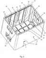
- the Fig. 1 shows a bottle crate 2 according to the invention in the form of a rectangular container with a rectangular bottle crate bottom 4 from the edges of which substantially vertically two long side walls 6 and two short side walls 8 extend. In the short side walls handle and view openings are formed.
- a truss 10 is used in the open-topped bottle crate 2 .
- the truss insert 10 has a framework-like structure, which has openings 12 which form bottle nests, in the bottles 14 (see Fig. 9 or 10 ) can be adjusted.
- the truss insert 10 has essentially the function to laterally support and separate the adjusted bottles 14.
- Bottle crate 2 and truss 10 are separately manufactured for bottle crate 2 component that can be inserted from above into the bottle crate 2 and also taken out of this again.
- Bottle crate 2 and truss 10 can be made of plastic, in particular by injection molding.
- the truss 10 is guided vertically on the two opposite long side walls 6 and slightly spaced from the two opposite short side walls 8.
- On the inner side 16 of the long side walls 6 are a plurality of guide grooves 18, 20 and 22, with respect to the Fig. 2 be described in detail.
- the Fig. 2 On the inside 16 of the long side wall 6 is a centrally arranged, semi-cylindrical shaped and extending from the bottle case bottom 4 to the bottle crate edge 24 extending Klein Replacementsnut 18 is formed. Asymmetric to the central main guide groove 18, a pair of long guide grooves 20 and a pair of short guide grooves 22 are formed. While the long guide grooves 20 extend from the bottle crate rim 24 substantially to the bottle crate bottom 4, the short guide grooves 22 only extend to a predetermined height H, which is located approximately in the lower third of the bottle crate 2.
- the main guide groove 18 serves for the general vertical guidance of the truss insert 10.
- FIG. 3 it can be seen, form the long guide grooves 20 with a pair of guide projections 30 which are formed on an outer side 34 of the truss 10, a first pair of guides.
- the short guide grooves 22 form with the guide projections 30 a second guide pair.
- the long guide grooves 20 and the short guide grooves 22 are formed on the opposite long side wall 6 exactly the other way round, so that when the truss 10 in the orientation, as in the Fig. 3 is inserted into the bottle crate 2, the two asymmetrically and on opposite sides arranged guide projections 30 are inserted into the short guide grooves 22.
- the truss 10 can be lowered only up to a height H, since the lower end of the short guide grooves 22 forms a stop for the guide projections 30.
- the guide projections 30 come into engagement with the long guide grooves 20 which extend to the bottle case bottom 4, which is why the truss 10 can be lowered to the bottle case bottom 4.
- the long and short guide grooves 20, 22 are slightly undercut and have for example a T-profile, so that the corresponding T-shaped projections 30 are trapped in the guide grooves 20 and 22, although vertically movable, but in the transverse direction.
- the T-shape is optional and not visualized in the figures.
- These guide grooves 20 and 22 may alternatively be round, square or dovetail-shaped.
- the long and short guide grooves 20, 22 run upwards open.
- one or more of the grooves 20, 22 also at the top of the bottle crate rim 24 be closed, so that the truss 10 can be removed only by slightly tilting out of the bottle crate 2.
- the long side wall 6 in a central portion has a slightly recessed wall portion 32, in which also the grooves 18, 20 and 22 are formed.
- the withdrawn wall section 32 serves as a sliding surface for an outer wall section or peripheral wall section 34 of the truss insert 10.
- truss ribs or projections 36 are formed, which are chamfered in the crossing points and pass into the bottle case bottom 4.
- the truss ribs 36 are substantially complementary to the surface design of the one side of the truss insert 10 (upper side in the Fig. 3 ), which has insertion chamfers 38 between the truss openings 12.
- the chamfers 38 are cross-shaped rising ribs at the intersection of the half-timbered partitions 40.
- the other side of the truss insert 10, ie the bottom in the Fig. 3 is flat so that when the truss 10 is turned over and lowered to the bottle crate bottom 4, as in the Fig. 1 and in detail in the Fig. 4 is shown, a flat footprint for the beverage composites 15 (see Fig. 9 ) offers.
- FIG. 4 is also very good to see the interaction of truss ribs 36 and insertion bevels 38, so that the truss 10 rests on all chamfers 38 and half-timbered partitions 40.
- the latticework insert 10 formed by the lattice-shaped half-timbered partitions 40 has in the corner regions of the openings 12 (see in particular Fig. 1 ) integrally formed cylindrical segments 42 (see in particular Fig. 3 ) on which the bottles used 14 support the surface horizontally.
- the FIG. 4 visualizes the interaction of selected or all guide grooves 20, each with at least one projection 30.
- groove and projection can also be such that the groove is present on the truss insert and the projection is formed on an inner wall of the bottle crate.
- the projection may be T-shaped or dovetail-shaped. Opposite grooves then allow an undercut and / or a grip behind.
- the Indian Fig. 3 shown truss insert 10 has 6 x 4 bottle spaces, the two outer, the short side walls 8 facing parking spaces are defined in conjunction with the short side wall 8.
- the latticework insert 10 has only separating projections 44, which are completed by corresponding truss lugs 46 which are formed in the edge region between the bottle case bottom 4 and the short side wall 8.
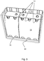
- the Fig. 5 shows a similar in basic form truss insert 50 according to a second embodiment, which can also be used with the bottle crate 2.
- This has no chamfers 38 and no guide projections 30.
- the truss insert 50 on the outside, which is associated with the inside 16 of the long side wall 6, a central semi-cylindrical main guide projection 52 which can slide vertically in the main guide 18.
- a pair of resilient locking tongues 54 are formed, which are designed with respect to their position and function so that they engage in the recesses 26 when the truss 50 is at the height H, and engage in the recesses 28 when the truss insert 50 is lowered to the bottle case bottom 4.
- the resilient locking tongues 54 yield and release the truss insert 50.
- the lock hook 56 and the recesses 26 and 28 may be formed so that the lock hook 56 is displaced by corresponding inclinations when reciprocated between the bottle case bottom 4 and the height H.
- the locking hook 56 and the recesses 26 are designed so that the truss can not be easily removed.
- the locking hooks 56 must be manually unlocked by the locking hooks 56, for example, with a sharp object such. As a screwdriver, pressed from the outside through the recess 26 through inside and released. This prevents that the truss 50 is not inadvertently removed from the bottle crate 2 in normal use. Instead of a manual unlocking the automatic unlocking can only be difficult.
- the truss 10 of the first embodiment in the truss insert 50 of the second embodiment is not a reversing fan insert and the truss 50 in the in the Fig. 5 shown orientation in the bottle crate 2 is introduced and can be moved without alignment changes between the height H and the bottle case bottom 4.
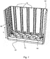
- the Fig. 6 shows a third embodiment of a truss 60, which is designed for a differently designed bottle crate 62, but in principle similar to the second embodiment.
- the truss 60 has a rectangular plate-shaped basic shape, which has a plurality of openings 64, the bottle nests form.
- On the short sides of the truss insert 60 is in each case a symmetrically arranged to the center Pair of snap elements 66 are arranged, which automatically engage in corresponding recesses 68, which are formed at the height H on the inside of the short side wall of the bottle crate 62.
- the snap elements 66 lock into corresponding recesses 72.
- the snap elements 66 In order to lift the truss 60 again, again the snap elements 66 must be pressed down to release the latch to the side walls of the bottle crate 62.
- the truss 60 has, on the long side, a plurality of sliding surface portions 74 that slide along respective inner surface portions 76 of the long side wall of the bottle crate 62. In addition, the truss 60 is also performed in sections on the short sides of the bottle crate 62.
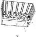
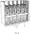
- FIGS. 9 and 10 show the example of the third embodiment, the principle of operation of the bottle crate according to the invention.
- Um like in the Fig. 9 shown to transport several beverage groups, ie several enveloped in cardboard boxes 15 bottles 14, the truss 60 can be lowered to the truss floor, so that the packaged bottles are flat on the hole plate-shaped truss 60 and are fully absorbed in the bottle crate 62.
- the cardboard boxes must be torn open, so that when returning the empties empty individual bottles must be transported, which are no longer held by the cardboard 15 and separated from each other.
- the truss 60 can be raised to a predetermined height H and due to the locking of the truss 60th with the bottle crate 62 remains the truss 60 in height H, so that the bottles 14 can be transported separated from each other and safely supported, as shown in the Fig. 10 is shown.
- the same principle is applicable to the second embodiment.
- the truss 10 In the first embodiment, however, the truss 10 must first be removed, turned by 180 ° about the horizontal axis A and used again. Due to the interaction of the different guide pairings, the truss 10 remains in the height H, which is suitable for the transport of the individual bottles.
- the truss insert can be designed for a larger number of smaller bottles and also for a smaller number of larger bottles.
- the outer dimensions or at least the guide portions or locking elements are designed according to the same, a variety of trusses can be used with the same described bottle crate.
- the bottle crate 2 of the first embodiment is designed for both a truss 10 according to the first embodiment and a truss 50 of the second embodiment.
- the bottle crate 2 can also be designed only for one embodiment, so that z. B. in the use of truss 10, the Klein Replacementsnut 18 and the recesses 26 and 28 and the use of a truss insert 50, the long and short guide grooves 20, 22 and the truss inserts 36 may be omitted.
- the features can be combined differently.
- the guide and / or latching of the truss 10 could be done instead of on the side walls 6 additionally or alternatively on so-called spars or quills in the center of the bottle crate.
- the sides of the turning tray insert 10 of the first embodiment can also be designed differently colored to align the truss 10 according to the desired use easier.
- the guide of the truss insert 10 takes place exclusively on the long side walls 6.
- the guides and the latches can also be formed on the short side.
- the guide on the long sides and the lock on the short sides or vice versa take place.
Landscapes
- Engineering & Computer Science (AREA)
- Mechanical Engineering (AREA)
- Ceramic Engineering (AREA)
- Details Of Rigid Or Semi-Rigid Containers (AREA)
Claims (14)
- Casier à bouteilles (2 ; 62) pourvu d'un insert en treillis (50 ; 60), en particulier présentant une forme de grille ou de plaque perforée, de préférence en plastique, servant à recevoir des bouteilles (14) ou des canettes, dans lequel l'insert en treillis (50 ; 60) guidé de manière verticale dans le casier à bouteilles (2 ; 62) peut être abaissé jusqu'au fond (4 ; 70) du casier à bouteilles et l'insert en treillis (50 ; 60) peut être positionné dans au moins une position en hauteur (H) prédéfinie espacée du fond (4 ; 70) du casier à bouteilles,
caractérisé en ce que
l'insert en treillis (50 ; 60) peut être retiré et peut être immobilisé par l'intermédiaire d'un mécanisme de verrouillage ou d'enclenchement (54, 56, 26, 28 ; 66 ; 68, 72) à la fois dans la position abaissée, dans laquelle l'insert en treillis est abaissé sur le fond (4 ; 70) du casier à bouteilles, et dans la position en hauteur (H) prédéfinie. - Casier à bouteilles (2 ; 62) selon la revendication 1, caractérisé en ce que l'insert en treillis (50 ; 60) présente au moins un élément de verrouillage ou d'enclenchement (54, 56 ; 66), qui peut coopérer par complémentarité de forme avec une géométrie de verrouillage ou d'encliquetage (26 ; 68) correspondante réalisée dans le casier à bouteilles (2 ; 62) au moins dans la position en hauteur (H) prédéfinie, en particulier effectue de manière autonome un verrouillage quand l'insert en treillis (50 ; 60) est amené dans la position en hauteur (H) correspondante.
- Casier à bouteilles (2 ; 62) selon l'une quelconque des revendications précédentes, caractérisé en ce que l'au moins un élément de verrouillage (54, 56 ; 66) situé côté treillis et/ou situé côté casier à bouteilles est précontraint élastiquement à la manière d'un ressort, en particulier de manière transversale par rapport à la direction en hauteur du casier à bouteilles (2 ; 62).
- Casier à bouteilles (2 ; 62) selon l'une quelconque des revendications précédentes, caractérisé en ce que
l'au moins un élément de verrouillage (54, 56 ; 66) est réalisé sous la forme d'une languette élastique (54 ; 66) ou d'un ergot d'encliquetage (56 ; 66) faisant saillie, laquelle/lequel vient en prise avec un évidement (26, 28 ; 68, 72) correspondant, qui est réalisé, au moins dans la position en hauteur (H) prédéfinie, au niveau au moins d'une colonne de guidage faisant saillie du fond (4), en particulier au niveau du fourreau, et/ou au niveau d'au moins une section de paroi latérale (16) du casier à bouteilles (2 ; 62). - Casier à bouteilles (2 ; 62) selon l'une quelconque des revendications 2 à 4, caractérisé en ce que l'au moins un élément de verrouillage ou d'enclenchement (54, 56 ; 66) est déverrouillé ou débloqué de manière autonome en présence d'une force appliquée dans la direction en hauteur sur l'insert en treillis (50 ; 60).
- Casier à bouteilles (2 ; 62) selon la revendication 5, caractérisé en ce qu'une première force, qui est nécessaire pour débloquer l'insert en treillis (50 ; 60) dans la direction d'abaissement, est inférieure à une deuxième force, qui est nécessaire pour débloquer l'insert en treillis (50 ; 60) dans la direction de relèvement.
- Casier à bouteilles (2 ; 62) selon la revendication 5 ou 6, caractérisé en ce que l'au moins un élément de verrouillage (54, 56 ; 66) effectue seulement de manière autonome un déverrouillage quand il est déplacé en direction du fond de bouteille depuis la position en hauteur (H) prédéfinie.
- Casier à bouteilles (2 ; 62) selon l'une quelconque des revendications 2 à 7, caractérisé en ce que l'au moins un élément de verrouillage (54, 56 ; 66) peut être déverrouillé manuellement.
- Casier à bouteilles (2) selon l'une quelconque des revendications précédentes, caractérisé en ce que l'insert en treillis (50) présente, au niveau d'un côté inférieur, une face de support plate et, au niveau d'un côté supérieur, des chanfreins d'introduction (38) réalisés entre des ouvertures de logement (12).
- Casier à bouteilles (2) selon la revendication 9, caractérisé en ce que la surface du fond (4) du casier à bouteilles est réalisée sensiblement de manière complémentaire au deuxième côté de l'insert en treillis (50).
- Casier à bouteilles (2 ; 62) selon l'une quelconque des revendications précédentes, caractérisé en ce que l'insert en treillis (50 ; 60) est guidé de manière verticale au niveau au moins d'une colonne de guidage faisant saillie du fond, en particulier au niveau du fourreau, et/ou au niveau d'au moins une paroi latérale (16 ; 74) du casier à bouteilles (2 ; 62).
- Casier à bouteilles (2 ; 62) selon la revendication 11, caractérisé en ce que l'au moins une paroi latérale (16) présente une section de guidage (18, 74) ouverte vers le haut, en particulier contre-dépouillée.
- Casier à bouteilles (2 ; 62) selon l'une quelconque des revendications précédentes, caractérisé en ce que l'insert en treillis (50 ; 60) présente des chanfreins d'introduction ou des entretoises/nervures d'introduction servant à centrer des unités d'emballage, telles que des bouteilles (14).
- Casier à bouteilles (2 ; 62) selon l'une quelconque des revendications 3 à 13, caractérisé en ce que l'au moins un élément de verrouillage (54, 56 ; 66) est réalisé sous la forme d'un composant séparé de l'insert en treillis (50 ; 60) et du matériau formant le casier à bouteilles (2 ; 62), lequel composant est inséré de préférence sous une précontrainte entre l'insert en treillis (50 ; 60) et le casier à bouteilles (2 ; 62).
Priority Applications (1)
| Application Number | Priority Date | Filing Date | Title |
|---|---|---|---|
| EP13177712.0A EP2829484B1 (fr) | 2013-07-23 | 2013-07-23 | Casier à bouteilles avec insert en treillis réglable en hauteur |
Applications Claiming Priority (1)
| Application Number | Priority Date | Filing Date | Title |
|---|---|---|---|
| EP13177712.0A EP2829484B1 (fr) | 2013-07-23 | 2013-07-23 | Casier à bouteilles avec insert en treillis réglable en hauteur |
Publications (2)
| Publication Number | Publication Date |
|---|---|
| EP2829484A1 EP2829484A1 (fr) | 2015-01-28 |
| EP2829484B1 true EP2829484B1 (fr) | 2017-08-30 |
Family
ID=48914053
Family Applications (1)
| Application Number | Title | Priority Date | Filing Date |
|---|---|---|---|
| EP13177712.0A Not-in-force EP2829484B1 (fr) | 2013-07-23 | 2013-07-23 | Casier à bouteilles avec insert en treillis réglable en hauteur |
Country Status (1)
| Country | Link |
|---|---|
| EP (1) | EP2829484B1 (fr) |
Cited By (1)
| Publication number | Priority date | Publication date | Assignee | Title |
|---|---|---|---|---|
| EP4556386A1 (fr) | 2023-11-18 | 2025-05-21 | DW Reusables N.V. | Caisse pour bouteilles de deux géométries sensiblement différentes |
Families Citing this family (19)
| Publication number | Priority date | Publication date | Assignee | Title |
|---|---|---|---|---|
| US20150166238A1 (en) * | 2013-12-16 | 2015-06-18 | Poly Flex Products, Inc. | Industrial container having removable dunnage |
| US11685573B2 (en) | 2017-06-12 | 2023-06-27 | Yeti Coolers, Llc | Carry strap for container |
| US11517086B2 (en) | 2019-01-06 | 2022-12-06 | Yeti Coolers, Llc | Luggage system |
| US12108853B2 (en) | 2019-01-06 | 2024-10-08 | Yeti Coolers, Llc | Luggage system |
| US11976498B2 (en) | 2017-06-12 | 2024-05-07 | Yeti Coolers, Llc | Container and latching system |
| AU201717615S (en) | 2017-06-12 | 2018-01-15 | Yeti Coolers | Container |
| CN110709332B (zh) | 2017-06-12 | 2021-09-03 | 野醍冷却器有限责任公司 | 容器和闩锁系统 |
| USD907445S1 (en) | 2018-12-11 | 2021-01-12 | Yeti Coolers, Llc | Container accessories |
| USD904829S1 (en) | 2018-12-11 | 2020-12-15 | Yeti Coolers, Llc | Container accessories |
| US12225993B2 (en) | 2019-01-06 | 2025-02-18 | Yeti Coolers, Llc | Luggage system |
| CN110667991A (zh) * | 2019-10-25 | 2020-01-10 | 徐州恒大食品有限公司 | 一种大蒜存储装置 |
| USD961926S1 (en) | 2020-06-30 | 2022-08-30 | Yeti Coolers, Llc | Luggage |
| USD951643S1 (en) | 2020-06-30 | 2022-05-17 | Yeti Coolers, Llc | Luggage |
| USD963344S1 (en) | 2020-06-30 | 2022-09-13 | Yeti Coolers, Llc | Luggage |
| USD954436S1 (en) | 2020-06-30 | 2022-06-14 | Yeti Coolers, Llc | Luggage |
| USD985937S1 (en) | 2020-12-16 | 2023-05-16 | Yeti Coolers, Llc | Container |
| USD960648S1 (en) | 2020-12-16 | 2022-08-16 | Yeti Coolers, Llc | Container accessory |
| USD994438S1 (en) | 2020-12-16 | 2023-08-08 | Yeti Coolers, Llc | Container |
| US12239815B2 (en) * | 2021-01-26 | 2025-03-04 | Becton Dickinson France | Tub for the packaging of a plurality of nests of plunger stoppers with guiding features ensuring a reliable location of the nests within the tub |
Family Cites Families (10)
| Publication number | Priority date | Publication date | Assignee | Title |
|---|---|---|---|---|
| US2119889A (en) | 1935-05-03 | 1938-06-07 | American Steel & Wire Co | Partition |
| DE1748170U (de) | 1957-03-29 | 1957-07-04 | Schaefer Kg Fritz | Einsatz fuer flaschenkaesten. |
| GB873288A (en) | 1959-02-11 | 1961-07-19 | W E Amies & Company Ltd | Improvements in crates for bottles |
| DE1839065U (de) | 1961-06-16 | 1961-10-05 | Karl Henninger | Kunststoff-flaschenkasten. |
| CH530913A (de) * | 1970-11-09 | 1972-11-30 | Utz Georg | Stapelbarer Harass für Behälter, insbesondere Flaschen, Dosen oder dgl. |
| US5392915A (en) * | 1993-09-03 | 1995-02-28 | Rehrig-Pacific Company, Inc. | Crate apparatus with adjustable lid |
| DE4340207A1 (de) | 1993-11-25 | 1995-06-01 | Schoeller Plast Ag | Flaschenkasten mit einem in das Kasteninnere einsetzbaren Fachwerk |
| CH690678A5 (de) * | 1996-11-01 | 2000-12-15 | Utz Georg Holding Ag | Einsatzteil für einen Behälter. |
| DE102004046323A1 (de) | 2004-09-17 | 2006-04-06 | Berndt & Partner Gmbh | Einsatz für Getränkekästen |
| DE102011055978B4 (de) * | 2011-12-02 | 2013-07-04 | Schoeller Arca Systems Gmbh | Flaschenkasten mit höhenverstellbarem Fachwerk |
-
2013
- 2013-07-23 EP EP13177712.0A patent/EP2829484B1/fr not_active Not-in-force
Non-Patent Citations (1)
| Title |
|---|
| None * |
Cited By (1)
| Publication number | Priority date | Publication date | Assignee | Title |
|---|---|---|---|---|
| EP4556386A1 (fr) | 2023-11-18 | 2025-05-21 | DW Reusables N.V. | Caisse pour bouteilles de deux géométries sensiblement différentes |
Also Published As
| Publication number | Publication date |
|---|---|
| EP2829484A1 (fr) | 2015-01-28 |
Similar Documents
| Publication | Publication Date | Title |
|---|---|---|
| EP2829484B1 (fr) | Casier à bouteilles avec insert en treillis réglable en hauteur | |
| EP2829485B1 (fr) | Casier à bouteilles avec insert en treillis réglable en hauteur | |
| EP0389802B1 (fr) | Récipient séparable en plusieurs parties, en particulier casier à bouteilles | |
| DE10026149C2 (de) | Stapelbarer Transportbehälter | |
| DE69321363T2 (de) | Flaschenkastenanordnung | |
| DE202014103695U1 (de) | Stapelbarer Behälter | |
| EP3636559B1 (fr) | Boîte empilable | |
| EP2878550A1 (fr) | Palette | |
| DE102019111950A1 (de) | Stapelbare Lagereinheit und Stapel aus Lagereinheiten | |
| EP3587294B1 (fr) | Récipient empilable pourvu de mécanisme de raccordement | |
| DE9218718U1 (de) | Teilpalette | |
| DE2525169C3 (de) | Kunststoff-Flaschenkasten mit Verriegelungsvorrichtung | |
| DE2104389A1 (de) | Gleichzeitig als Flaschenträger und Stapelkasten ausgebildeter Flaschenkasten | |
| EP0374774A2 (fr) | Casiers à bouteilles avec des éléments horizontaux servant de poignées | |
| EP1733975A1 (fr) | Contenant repliable | |
| EP0698558A2 (fr) | Récipient de transport empilable | |
| DE102014111337A1 (de) | Stapelbarer Behälter | |
| EP1713696B1 (fr) | Bac de rangement | |
| DE3621029C2 (fr) | ||
| DE202004014340U1 (de) | Drehstapelbehälter | |
| DE102006016031A1 (de) | Stapelbarer Transportbehälter | |
| EP3012205B1 (fr) | Caisse a bouteilles divisible | |
| EP3015382B1 (fr) | Caisse divisible | |
| AT521025B1 (de) | Stapelbare Kiste | |
| DE20009499U1 (de) | Stapelbarer Transportbehälter |
Legal Events
| Date | Code | Title | Description |
|---|---|---|---|
| 17P | Request for examination filed |
Effective date: 20130723 |
|
| AK | Designated contracting states |
Kind code of ref document: A1 Designated state(s): AL AT BE BG CH CY CZ DE DK EE ES FI FR GB GR HR HU IE IS IT LI LT LU LV MC MK MT NL NO PL PT RO RS SE SI SK SM TR |
|
| AX | Request for extension of the european patent |
Extension state: BA ME |
|
| PUAI | Public reference made under article 153(3) epc to a published international application that has entered the european phase |
Free format text: ORIGINAL CODE: 0009012 |
|
| R17P | Request for examination filed (corrected) |
Effective date: 20150629 |
|
| RBV | Designated contracting states (corrected) |
Designated state(s): AL AT BE BG CH CY CZ DE DK EE ES FI FR GB GR HR HU IE IS IT LI LT LU LV MC MK MT NL NO PL PT RO RS SE SI SK SM TR |
|
| 17Q | First examination report despatched |
Effective date: 20151116 |
|
| REG | Reference to a national code |
Ref country code: DE Ref legal event code: R079 Ref document number: 502013008188 Country of ref document: DE Free format text: PREVIOUS MAIN CLASS: B65D0001240000 Ipc: B65D0025100000 |
|
| GRAP | Despatch of communication of intention to grant a patent |
Free format text: ORIGINAL CODE: EPIDOSNIGR1 |
|
| RIC1 | Information provided on ipc code assigned before grant |
Ipc: B65D 1/24 20060101ALI20170215BHEP Ipc: B65D 25/10 20060101AFI20170215BHEP |
|
| INTG | Intention to grant announced |
Effective date: 20170310 |
|
| GRAS | Grant fee paid |
Free format text: ORIGINAL CODE: EPIDOSNIGR3 |
|
| GRAA | (expected) grant |
Free format text: ORIGINAL CODE: 0009210 |
|
| AK | Designated contracting states |
Kind code of ref document: B1 Designated state(s): AL AT BE BG CH CY CZ DE DK EE ES FI FR GB GR HR HU IE IS IT LI LT LU LV MC MK MT NL NO PL PT RO RS SE SI SK SM TR |
|
| REG | Reference to a national code |
Ref country code: GB Ref legal event code: FG4D Free format text: NOT ENGLISH |
|
| REG | Reference to a national code |
Ref country code: CH Ref legal event code: EP |
|
| REG | Reference to a national code |
Ref country code: AT Ref legal event code: REF Ref document number: 923295 Country of ref document: AT Kind code of ref document: T Effective date: 20170915 |
|
| REG | Reference to a national code |
Ref country code: IE Ref legal event code: FG4D Free format text: LANGUAGE OF EP DOCUMENT: GERMAN |
|
| REG | Reference to a national code |
Ref country code: DE Ref legal event code: R096 Ref document number: 502013008188 Country of ref document: DE |
|
| REG | Reference to a national code |
Ref country code: NL Ref legal event code: FP |
|
| REG | Reference to a national code |
Ref country code: LT Ref legal event code: MG4D |
|
| PG25 | Lapsed in a contracting state [announced via postgrant information from national office to epo] |
Ref country code: NO Free format text: LAPSE BECAUSE OF FAILURE TO SUBMIT A TRANSLATION OF THE DESCRIPTION OR TO PAY THE FEE WITHIN THE PRESCRIBED TIME-LIMIT Effective date: 20171130 Ref country code: FI Free format text: LAPSE BECAUSE OF FAILURE TO SUBMIT A TRANSLATION OF THE DESCRIPTION OR TO PAY THE FEE WITHIN THE PRESCRIBED TIME-LIMIT Effective date: 20170830 Ref country code: SE Free format text: LAPSE BECAUSE OF FAILURE TO SUBMIT A TRANSLATION OF THE DESCRIPTION OR TO PAY THE FEE WITHIN THE PRESCRIBED TIME-LIMIT Effective date: 20170830 Ref country code: LT Free format text: LAPSE BECAUSE OF FAILURE TO SUBMIT A TRANSLATION OF THE DESCRIPTION OR TO PAY THE FEE WITHIN THE PRESCRIBED TIME-LIMIT Effective date: 20170830 Ref country code: HR Free format text: LAPSE BECAUSE OF FAILURE TO SUBMIT A TRANSLATION OF THE DESCRIPTION OR TO PAY THE FEE WITHIN THE PRESCRIBED TIME-LIMIT Effective date: 20170830 |
|
| PG25 | Lapsed in a contracting state [announced via postgrant information from national office to epo] |
Ref country code: RS Free format text: LAPSE BECAUSE OF FAILURE TO SUBMIT A TRANSLATION OF THE DESCRIPTION OR TO PAY THE FEE WITHIN THE PRESCRIBED TIME-LIMIT Effective date: 20170830 Ref country code: BG Free format text: LAPSE BECAUSE OF FAILURE TO SUBMIT A TRANSLATION OF THE DESCRIPTION OR TO PAY THE FEE WITHIN THE PRESCRIBED TIME-LIMIT Effective date: 20171130 Ref country code: ES Free format text: LAPSE BECAUSE OF FAILURE TO SUBMIT A TRANSLATION OF THE DESCRIPTION OR TO PAY THE FEE WITHIN THE PRESCRIBED TIME-LIMIT Effective date: 20170830 Ref country code: LV Free format text: LAPSE BECAUSE OF FAILURE TO SUBMIT A TRANSLATION OF THE DESCRIPTION OR TO PAY THE FEE WITHIN THE PRESCRIBED TIME-LIMIT Effective date: 20170830 Ref country code: GR Free format text: LAPSE BECAUSE OF FAILURE TO SUBMIT A TRANSLATION OF THE DESCRIPTION OR TO PAY THE FEE WITHIN THE PRESCRIBED TIME-LIMIT Effective date: 20171201 Ref country code: IS Free format text: LAPSE BECAUSE OF FAILURE TO SUBMIT A TRANSLATION OF THE DESCRIPTION OR TO PAY THE FEE WITHIN THE PRESCRIBED TIME-LIMIT Effective date: 20171230 |
|
| PG25 | Lapsed in a contracting state [announced via postgrant information from national office to epo] |
Ref country code: CZ Free format text: LAPSE BECAUSE OF FAILURE TO SUBMIT A TRANSLATION OF THE DESCRIPTION OR TO PAY THE FEE WITHIN THE PRESCRIBED TIME-LIMIT Effective date: 20170830 Ref country code: RO Free format text: LAPSE BECAUSE OF FAILURE TO SUBMIT A TRANSLATION OF THE DESCRIPTION OR TO PAY THE FEE WITHIN THE PRESCRIBED TIME-LIMIT Effective date: 20170830 Ref country code: PL Free format text: LAPSE BECAUSE OF FAILURE TO SUBMIT A TRANSLATION OF THE DESCRIPTION OR TO PAY THE FEE WITHIN THE PRESCRIBED TIME-LIMIT Effective date: 20170830 Ref country code: DK Free format text: LAPSE BECAUSE OF FAILURE TO SUBMIT A TRANSLATION OF THE DESCRIPTION OR TO PAY THE FEE WITHIN THE PRESCRIBED TIME-LIMIT Effective date: 20170830 |
|
| PG25 | Lapsed in a contracting state [announced via postgrant information from national office to epo] |
Ref country code: IT Free format text: LAPSE BECAUSE OF FAILURE TO SUBMIT A TRANSLATION OF THE DESCRIPTION OR TO PAY THE FEE WITHIN THE PRESCRIBED TIME-LIMIT Effective date: 20170830 Ref country code: EE Free format text: LAPSE BECAUSE OF FAILURE TO SUBMIT A TRANSLATION OF THE DESCRIPTION OR TO PAY THE FEE WITHIN THE PRESCRIBED TIME-LIMIT Effective date: 20170830 Ref country code: SK Free format text: LAPSE BECAUSE OF FAILURE TO SUBMIT A TRANSLATION OF THE DESCRIPTION OR TO PAY THE FEE WITHIN THE PRESCRIBED TIME-LIMIT Effective date: 20170830 Ref country code: SM Free format text: LAPSE BECAUSE OF FAILURE TO SUBMIT A TRANSLATION OF THE DESCRIPTION OR TO PAY THE FEE WITHIN THE PRESCRIBED TIME-LIMIT Effective date: 20170830 |
|
| REG | Reference to a national code |
Ref country code: DE Ref legal event code: R097 Ref document number: 502013008188 Country of ref document: DE |
|
| PLBE | No opposition filed within time limit |
Free format text: ORIGINAL CODE: 0009261 |
|
| STAA | Information on the status of an ep patent application or granted ep patent |
Free format text: STATUS: NO OPPOSITION FILED WITHIN TIME LIMIT |
|
| 26N | No opposition filed |
Effective date: 20180531 |
|
| PG25 | Lapsed in a contracting state [announced via postgrant information from national office to epo] |
Ref country code: SI Free format text: LAPSE BECAUSE OF FAILURE TO SUBMIT A TRANSLATION OF THE DESCRIPTION OR TO PAY THE FEE WITHIN THE PRESCRIBED TIME-LIMIT Effective date: 20170830 |
|
| PG25 | Lapsed in a contracting state [announced via postgrant information from national office to epo] |
Ref country code: MT Free format text: LAPSE BECAUSE OF FAILURE TO SUBMIT A TRANSLATION OF THE DESCRIPTION OR TO PAY THE FEE WITHIN THE PRESCRIBED TIME-LIMIT Effective date: 20170830 |
|
| REG | Reference to a national code |
Ref country code: CH Ref legal event code: PL |
|
| GBPC | Gb: european patent ceased through non-payment of renewal fee |
Effective date: 20180723 |
|
| PG25 | Lapsed in a contracting state [announced via postgrant information from national office to epo] |
Ref country code: MC Free format text: LAPSE BECAUSE OF FAILURE TO SUBMIT A TRANSLATION OF THE DESCRIPTION OR TO PAY THE FEE WITHIN THE PRESCRIBED TIME-LIMIT Effective date: 20170830 Ref country code: LU Free format text: LAPSE BECAUSE OF NON-PAYMENT OF DUE FEES Effective date: 20180723 |
|
| REG | Reference to a national code |
Ref country code: IE Ref legal event code: MM4A |
|
| PG25 | Lapsed in a contracting state [announced via postgrant information from national office to epo] |
Ref country code: GB Free format text: LAPSE BECAUSE OF NON-PAYMENT OF DUE FEES Effective date: 20180723 Ref country code: IE Free format text: LAPSE BECAUSE OF NON-PAYMENT OF DUE FEES Effective date: 20180723 Ref country code: FR Free format text: LAPSE BECAUSE OF NON-PAYMENT OF DUE FEES Effective date: 20180731 Ref country code: LI Free format text: LAPSE BECAUSE OF NON-PAYMENT OF DUE FEES Effective date: 20180731 Ref country code: CH Free format text: LAPSE BECAUSE OF NON-PAYMENT OF DUE FEES Effective date: 20180731 |
|
| PGFP | Annual fee paid to national office [announced via postgrant information from national office to epo] |
Ref country code: NL Payment date: 20190722 Year of fee payment: 7 |
|
| REG | Reference to a national code |
Ref country code: AT Ref legal event code: MM01 Ref document number: 923295 Country of ref document: AT Kind code of ref document: T Effective date: 20180723 |
|
| PGFP | Annual fee paid to national office [announced via postgrant information from national office to epo] |
Ref country code: DE Payment date: 20190628 Year of fee payment: 7 |
|
| PGFP | Annual fee paid to national office [announced via postgrant information from national office to epo] |
Ref country code: BE Payment date: 20190722 Year of fee payment: 7 |
|
| PG25 | Lapsed in a contracting state [announced via postgrant information from national office to epo] |
Ref country code: AT Free format text: LAPSE BECAUSE OF NON-PAYMENT OF DUE FEES Effective date: 20180723 |
|
| PG25 | Lapsed in a contracting state [announced via postgrant information from national office to epo] |
Ref country code: TR Free format text: LAPSE BECAUSE OF FAILURE TO SUBMIT A TRANSLATION OF THE DESCRIPTION OR TO PAY THE FEE WITHIN THE PRESCRIBED TIME-LIMIT Effective date: 20170830 |
|
| PG25 | Lapsed in a contracting state [announced via postgrant information from national office to epo] |
Ref country code: PT Free format text: LAPSE BECAUSE OF FAILURE TO SUBMIT A TRANSLATION OF THE DESCRIPTION OR TO PAY THE FEE WITHIN THE PRESCRIBED TIME-LIMIT Effective date: 20170830 Ref country code: HU Free format text: LAPSE BECAUSE OF FAILURE TO SUBMIT A TRANSLATION OF THE DESCRIPTION OR TO PAY THE FEE WITHIN THE PRESCRIBED TIME-LIMIT; INVALID AB INITIO Effective date: 20130723 |
|
| PG25 | Lapsed in a contracting state [announced via postgrant information from national office to epo] |
Ref country code: MK Free format text: LAPSE BECAUSE OF NON-PAYMENT OF DUE FEES Effective date: 20170830 Ref country code: CY Free format text: LAPSE BECAUSE OF FAILURE TO SUBMIT A TRANSLATION OF THE DESCRIPTION OR TO PAY THE FEE WITHIN THE PRESCRIBED TIME-LIMIT Effective date: 20170830 |
|
| PG25 | Lapsed in a contracting state [announced via postgrant information from national office to epo] |
Ref country code: AL Free format text: LAPSE BECAUSE OF FAILURE TO SUBMIT A TRANSLATION OF THE DESCRIPTION OR TO PAY THE FEE WITHIN THE PRESCRIBED TIME-LIMIT Effective date: 20170830 |
|
| REG | Reference to a national code |
Ref country code: DE Ref legal event code: R119 Ref document number: 502013008188 Country of ref document: DE |
|
| REG | Reference to a national code |
Ref country code: NL Ref legal event code: MM Effective date: 20200801 |
|
| REG | Reference to a national code |
Ref country code: BE Ref legal event code: MM Effective date: 20200731 |
|
| PG25 | Lapsed in a contracting state [announced via postgrant information from national office to epo] |
Ref country code: NL Free format text: LAPSE BECAUSE OF NON-PAYMENT OF DUE FEES Effective date: 20200801 |
|
| PG25 | Lapsed in a contracting state [announced via postgrant information from national office to epo] |
Ref country code: DE Free format text: LAPSE BECAUSE OF NON-PAYMENT OF DUE FEES Effective date: 20210202 Ref country code: BE Free format text: LAPSE BECAUSE OF NON-PAYMENT OF DUE FEES Effective date: 20200731 |