EP2829403B1 - Dispositif d'application de mélanges de matières à concentration constante sur une bande de matériau et procédé de nettoyage des gaz d'échappement du dispositif - Google Patents
Dispositif d'application de mélanges de matières à concentration constante sur une bande de matériau et procédé de nettoyage des gaz d'échappement du dispositif Download PDFInfo
- Publication number
- EP2829403B1 EP2829403B1 EP14178154.2A EP14178154A EP2829403B1 EP 2829403 B1 EP2829403 B1 EP 2829403B1 EP 14178154 A EP14178154 A EP 14178154A EP 2829403 B1 EP2829403 B1 EP 2829403B1
- Authority
- EP
- European Patent Office
- Prior art keywords
- exhaust gas
- gas flow
- drying
- solvent
- concentration
- Prior art date
- Legal status (The legal status is an assumption and is not a legal conclusion. Google has not performed a legal analysis and makes no representation as to the accuracy of the status listed.)
- Active
Links
- 239000000463 material Substances 0.000 title claims description 55
- 239000000203 mixture Substances 0.000 title claims description 51
- 239000000126 substance Substances 0.000 title claims description 36
- 238000000034 method Methods 0.000 title claims description 21
- 238000004140 cleaning Methods 0.000 title description 2
- 239000002912 waste gas Substances 0.000 title 1
- 239000007789 gas Substances 0.000 claims description 300
- 238000001035 drying Methods 0.000 claims description 135
- 239000002904 solvent Substances 0.000 claims description 87
- 230000003197 catalytic effect Effects 0.000 claims description 77
- 238000007254 oxidation reaction Methods 0.000 claims description 77
- 230000003647 oxidation Effects 0.000 claims description 76
- 238000012545 processing Methods 0.000 claims description 54
- 239000003054 catalyst Substances 0.000 claims description 29
- 238000006243 chemical reaction Methods 0.000 claims description 24
- 230000001105 regulatory effect Effects 0.000 claims description 16
- QVGXLLKOCUKJST-UHFFFAOYSA-N atomic oxygen Chemical compound [O] QVGXLLKOCUKJST-UHFFFAOYSA-N 0.000 claims description 13
- 239000003960 organic solvent Substances 0.000 claims description 13
- 239000001301 oxygen Substances 0.000 claims description 13
- 229910052760 oxygen Inorganic materials 0.000 claims description 13
- 230000033228 biological regulation Effects 0.000 claims description 5
- 238000007664 blowing Methods 0.000 claims description 3
- 238000004891 communication Methods 0.000 claims 1
- 239000003570 air Substances 0.000 description 44
- 238000010438 heat treatment Methods 0.000 description 33
- LFQSCWFLJHTTHZ-UHFFFAOYSA-N Ethanol Chemical compound CCO LFQSCWFLJHTTHZ-UHFFFAOYSA-N 0.000 description 16
- 238000007639 printing Methods 0.000 description 14
- 230000001276 controlling effect Effects 0.000 description 8
- 230000008569 process Effects 0.000 description 8
- 238000003754 machining Methods 0.000 description 7
- XEKOWRVHYACXOJ-UHFFFAOYSA-N Ethyl acetate Chemical compound CCOC(C)=O XEKOWRVHYACXOJ-UHFFFAOYSA-N 0.000 description 6
- 238000013461 design Methods 0.000 description 6
- 238000004880 explosion Methods 0.000 description 6
- 238000011144 upstream manufacturing Methods 0.000 description 6
- 230000000694 effects Effects 0.000 description 5
- 238000010586 diagram Methods 0.000 description 4
- 239000003344 environmental pollutant Substances 0.000 description 4
- 230000002349 favourable effect Effects 0.000 description 4
- 231100000719 pollutant Toxicity 0.000 description 4
- 230000005855 radiation Effects 0.000 description 4
- 230000009467 reduction Effects 0.000 description 4
- OKKJLVBELUTLKV-UHFFFAOYSA-N Methanol Chemical compound OC OKKJLVBELUTLKV-UHFFFAOYSA-N 0.000 description 3
- 238000010521 absorption reaction Methods 0.000 description 3
- 230000009471 action Effects 0.000 description 3
- 230000008901 benefit Effects 0.000 description 3
- 238000006555 catalytic reaction Methods 0.000 description 3
- 238000000576 coating method Methods 0.000 description 3
- 238000002485 combustion reaction Methods 0.000 description 3
- 230000007613 environmental effect Effects 0.000 description 3
- 229910000510 noble metal Inorganic materials 0.000 description 3
- 230000001590 oxidative effect Effects 0.000 description 3
- 239000003973 paint Substances 0.000 description 3
- 230000004044 response Effects 0.000 description 3
- 238000004088 simulation Methods 0.000 description 3
- 239000012855 volatile organic compound Substances 0.000 description 3
- CSCPPACGZOOCGX-UHFFFAOYSA-N Acetone Chemical compound CC(C)=O CSCPPACGZOOCGX-UHFFFAOYSA-N 0.000 description 2
- UGFAIRIUMAVXCW-UHFFFAOYSA-N Carbon monoxide Chemical compound [O+]#[C-] UGFAIRIUMAVXCW-UHFFFAOYSA-N 0.000 description 2
- MYMOFIZGZYHOMD-UHFFFAOYSA-N Dioxygen Chemical compound O=O MYMOFIZGZYHOMD-UHFFFAOYSA-N 0.000 description 2
- KFZMGEQAYNKOFK-UHFFFAOYSA-N Isopropanol Chemical compound CC(C)O KFZMGEQAYNKOFK-UHFFFAOYSA-N 0.000 description 2
- 230000004913 activation Effects 0.000 description 2
- 239000012080 ambient air Substances 0.000 description 2
- 239000011248 coating agent Substances 0.000 description 2
- 150000001875 compounds Chemical class 0.000 description 2
- 238000000354 decomposition reaction Methods 0.000 description 2
- 238000011161 development Methods 0.000 description 2
- 230000018109 developmental process Effects 0.000 description 2
- 238000001704 evaporation Methods 0.000 description 2
- 230000008020 evaporation Effects 0.000 description 2
- 238000013213 extrapolation Methods 0.000 description 2
- 239000003546 flue gas Substances 0.000 description 2
- 238000004519 manufacturing process Methods 0.000 description 2
- 229910044991 metal oxide Inorganic materials 0.000 description 2
- 229910003455 mixed metal oxide Inorganic materials 0.000 description 2
- 238000002156 mixing Methods 0.000 description 2
- VLKZOEOYAKHREP-UHFFFAOYSA-N n-Hexane Chemical compound CCCCCC VLKZOEOYAKHREP-UHFFFAOYSA-N 0.000 description 2
- 125000004430 oxygen atom Chemical group O* 0.000 description 2
- 230000036961 partial effect Effects 0.000 description 2
- 239000004033 plastic Substances 0.000 description 2
- 229920003023 plastic Polymers 0.000 description 2
- 238000000746 purification Methods 0.000 description 2
- 230000003134 recirculating effect Effects 0.000 description 2
- 229920006395 saturated elastomer Polymers 0.000 description 2
- -1 sheets Substances 0.000 description 2
- 239000007921 spray Substances 0.000 description 2
- 239000002023 wood Substances 0.000 description 2
- 230000002411 adverse Effects 0.000 description 1
- 238000005273 aeration Methods 0.000 description 1
- 125000004429 atom Chemical group 0.000 description 1
- BTANRVKWQNVYAZ-UHFFFAOYSA-N butan-2-ol Chemical compound CCC(C)O BTANRVKWQNVYAZ-UHFFFAOYSA-N 0.000 description 1
- 238000004364 calculation method Methods 0.000 description 1
- 239000000969 carrier Substances 0.000 description 1
- 230000015556 catabolic process Effects 0.000 description 1
- 239000011093 chipboard Substances 0.000 description 1
- 239000000567 combustion gas Substances 0.000 description 1
- 230000000295 complement effect Effects 0.000 description 1
- 239000002131 composite material Substances 0.000 description 1
- 239000000470 constituent Substances 0.000 description 1
- 238000001816 cooling Methods 0.000 description 1
- 230000007423 decrease Effects 0.000 description 1
- 238000006731 degradation reaction Methods 0.000 description 1
- 230000001419 dependent effect Effects 0.000 description 1
- 229910001882 dioxygen Inorganic materials 0.000 description 1
- 239000002270 dispersing agent Substances 0.000 description 1
- 238000011156 evaluation Methods 0.000 description 1
- 239000002360 explosive Substances 0.000 description 1
- 239000010408 film Substances 0.000 description 1
- 239000012530 fluid Substances 0.000 description 1
- 239000011521 glass Substances 0.000 description 1
- 239000004922 lacquer Substances 0.000 description 1
- 239000007788 liquid Substances 0.000 description 1
- 238000013178 mathematical model Methods 0.000 description 1
- 238000005259 measurement Methods 0.000 description 1
- 229910052751 metal Inorganic materials 0.000 description 1
- 239000002184 metal Substances 0.000 description 1
- 150000004706 metal oxides Chemical class 0.000 description 1
- 238000012821 model calculation Methods 0.000 description 1
- 239000005022 packaging material Substances 0.000 description 1
- 238000010422 painting Methods 0.000 description 1
- 239000000123 paper Substances 0.000 description 1
- AQIXEPGDORPWBJ-UHFFFAOYSA-N pentan-3-ol Chemical compound CCC(O)CC AQIXEPGDORPWBJ-UHFFFAOYSA-N 0.000 description 1
- 239000000049 pigment Substances 0.000 description 1
- 239000004014 plasticizer Substances 0.000 description 1
- 239000010970 precious metal Substances 0.000 description 1
- BDERNNFJNOPAEC-UHFFFAOYSA-N propan-1-ol Chemical compound CCCO BDERNNFJNOPAEC-UHFFFAOYSA-N 0.000 description 1
- 238000011084 recovery Methods 0.000 description 1
- 230000001172 regenerating effect Effects 0.000 description 1
- 238000005096 rolling process Methods 0.000 description 1
- 239000011877 solvent mixture Substances 0.000 description 1
- 229910052566 spinel group Inorganic materials 0.000 description 1
- 230000002123 temporal effect Effects 0.000 description 1
- 230000036962 time dependent Effects 0.000 description 1
- 230000001960 triggered effect Effects 0.000 description 1
- 238000009423 ventilation Methods 0.000 description 1
- XLYOFNOQVPJJNP-UHFFFAOYSA-N water Substances O XLYOFNOQVPJJNP-UHFFFAOYSA-N 0.000 description 1
- 238000004804 winding Methods 0.000 description 1
Images


Classifications
-
- B—PERFORMING OPERATIONS; TRANSPORTING
- B41—PRINTING; LINING MACHINES; TYPEWRITERS; STAMPS
- B41F—PRINTING MACHINES OR PRESSES
- B41F31/00—Inking arrangements or devices
- B41F31/02—Ducts, containers, supply or metering devices
-
- B—PERFORMING OPERATIONS; TRANSPORTING
- B41—PRINTING; LINING MACHINES; TYPEWRITERS; STAMPS
- B41F—PRINTING MACHINES OR PRESSES
- B41F23/00—Devices for treating the surfaces of sheets, webs, or other articles in connection with printing
- B41F23/04—Devices for treating the surfaces of sheets, webs, or other articles in connection with printing by heat drying, by cooling, by applying powders
- B41F23/0403—Drying webs
- B41F23/0423—Drying webs by convection
- B41F23/0426—Drying webs by convection using heated air
-
- B—PERFORMING OPERATIONS; TRANSPORTING
- B41—PRINTING; LINING MACHINES; TYPEWRITERS; STAMPS
- B41F—PRINTING MACHINES OR PRESSES
- B41F23/00—Devices for treating the surfaces of sheets, webs, or other articles in connection with printing
- B41F23/04—Devices for treating the surfaces of sheets, webs, or other articles in connection with printing by heat drying, by cooling, by applying powders
- B41F23/044—Drying sheets, e.g. between two printing stations
- B41F23/0463—Drying sheets, e.g. between two printing stations by convection
- B41F23/0466—Drying sheets, e.g. between two printing stations by convection by using heated air
-
- B—PERFORMING OPERATIONS; TRANSPORTING
- B41—PRINTING; LINING MACHINES; TYPEWRITERS; STAMPS
- B41F—PRINTING MACHINES OR PRESSES
- B41F5/00—Rotary letterpress machines
- B41F5/24—Rotary letterpress machines for flexographic printing
-
- B—PERFORMING OPERATIONS; TRANSPORTING
- B41—PRINTING; LINING MACHINES; TYPEWRITERS; STAMPS
- B41J—TYPEWRITERS; SELECTIVE PRINTING MECHANISMS, i.e. MECHANISMS PRINTING OTHERWISE THAN FROM A FORME; CORRECTION OF TYPOGRAPHICAL ERRORS
- B41J11/00—Devices or arrangements of selective printing mechanisms, e.g. ink-jet printers or thermal printers, for supporting or handling copy material in sheet or web form
- B41J11/0015—Devices or arrangements of selective printing mechanisms, e.g. ink-jet printers or thermal printers, for supporting or handling copy material in sheet or web form for treating before, during or after printing or for uniform coating or laminating the copy material before or after printing
- B41J11/002—Curing or drying the ink on the copy materials, e.g. by heating or irradiating
- B41J11/0021—Curing or drying the ink on the copy materials, e.g. by heating or irradiating using irradiation
-
- B—PERFORMING OPERATIONS; TRANSPORTING
- B41—PRINTING; LINING MACHINES; TYPEWRITERS; STAMPS
- B41J—TYPEWRITERS; SELECTIVE PRINTING MECHANISMS, i.e. MECHANISMS PRINTING OTHERWISE THAN FROM A FORME; CORRECTION OF TYPOGRAPHICAL ERRORS
- B41J11/00—Devices or arrangements of selective printing mechanisms, e.g. ink-jet printers or thermal printers, for supporting or handling copy material in sheet or web form
- B41J11/0015—Devices or arrangements of selective printing mechanisms, e.g. ink-jet printers or thermal printers, for supporting or handling copy material in sheet or web form for treating before, during or after printing or for uniform coating or laminating the copy material before or after printing
- B41J11/002—Curing or drying the ink on the copy materials, e.g. by heating or irradiating
- B41J11/0021—Curing or drying the ink on the copy materials, e.g. by heating or irradiating using irradiation
- B41J11/00216—Curing or drying the ink on the copy materials, e.g. by heating or irradiating using irradiation using infrared [IR] radiation or microwaves
-
- B—PERFORMING OPERATIONS; TRANSPORTING
- B41—PRINTING; LINING MACHINES; TYPEWRITERS; STAMPS
- B41J—TYPEWRITERS; SELECTIVE PRINTING MECHANISMS, i.e. MECHANISMS PRINTING OTHERWISE THAN FROM A FORME; CORRECTION OF TYPOGRAPHICAL ERRORS
- B41J11/00—Devices or arrangements of selective printing mechanisms, e.g. ink-jet printers or thermal printers, for supporting or handling copy material in sheet or web form
- B41J11/0015—Devices or arrangements of selective printing mechanisms, e.g. ink-jet printers or thermal printers, for supporting or handling copy material in sheet or web form for treating before, during or after printing or for uniform coating or laminating the copy material before or after printing
- B41J11/002—Curing or drying the ink on the copy materials, e.g. by heating or irradiating
- B41J11/0022—Curing or drying the ink on the copy materials, e.g. by heating or irradiating using convection means, e.g. by using a fan for blowing or sucking air
-
- B—PERFORMING OPERATIONS; TRANSPORTING
- B41—PRINTING; LINING MACHINES; TYPEWRITERS; STAMPS
- B41J—TYPEWRITERS; SELECTIVE PRINTING MECHANISMS, i.e. MECHANISMS PRINTING OTHERWISE THAN FROM A FORME; CORRECTION OF TYPOGRAPHICAL ERRORS
- B41J2/00—Typewriters or selective printing mechanisms characterised by the printing or marking process for which they are designed
- B41J2/005—Typewriters or selective printing mechanisms characterised by the printing or marking process for which they are designed characterised by bringing liquid or particles selectively into contact with a printing material
- B41J2/01—Ink jet
- B41J2/17—Ink jet characterised by ink handling
- B41J2/1714—Conditioning of the outside of ink supply systems, e.g. inkjet collector cleaning, ink mist removal
Definitions
- the invention relates to a device for applying in each case at least one organic solvent-containing mixtures to a material web.
- the invention further relates to a method for providing a portion of an exhaust gas stream for a catalytic oxidation unit integrated in the apparatus.
- Device and method are generically from the DE 103 57 559 A1 known.
- solvent-containing mixtures such as paints, coatings or plastic mixtures
- solvent it is then usually to evaporation of the solvent, the z. B. to solve paint or paint components or act as a plasticizer.
- the evaporation rate of the solvent depends on various conditions, such as the type of solvent or solvent (s), the solvent temperature, the ambient temperatures, the ventilation intensity or the ambient pressures from.
- the at least one solvent serves, inter alia, to keep the mixture sufficiently liquid to a To allow trouble-free processing and to achieve good adhesion of the mixture on the surface of the material.
- Solvent-containing mixtures are applied to webs of material, for example, printed, a concentration of the solvent in the applied mixtures must be quickly lowered so far that overprinting or winding of the web is possible without causing blurring of the applied mixture.
- the reduction of the solvent concentration is usually carried out by drying the applied substance mixture by the supply of air streams or by irradiation, for example with infrared radiation.
- the drying may include, in addition to a reduction in the solvent concentration contained in the applied mixture, a decomposition or conversion of substances of the mixture. The drying parameters are adjusted to the desired printing speed.
- the air used for drying is loaded after drying with solvent and / or decomposition products and is discharged as exhaust gas flow from the web.
- the indication of a lower explosion limit (LEL) and an upper explosion limit (LEL) in grams of solvent per cubic meter indicates an impermissible value range of the solvent concentration.
- the solvents must be suitably treated so that the exhaust gas flow can be released to the environment in compliance with environmental and occupational safety regulations. Cleaning is usually carried out by a thermal reaction of the solvents contained in the exhaust gas stream or in a portion of the exhaust gas stream.
- a thermal reaction is an oxidative process, which is preferably carried out in the presence of a suitable catalyst.
- a suitable catalyst Important here is the relationship between oxygen and pollutant.
- the oxidizable amount of pollutants is determined by the amount of oxygen available.
- noble metal catalysts there must be at least an excess of oxygen of 2%. If metal oxide compounds are used, the excess is at least 12%.
- the solvent-containing exhaust gas stream can be purified by means of a catalytic post-combustion system, which can be integrated in a flexographic printing machine.
- catalytic afterburning heat energy is released, which is available for heating the exhaust gas before it is fed to the catalytic afterburner (henceforth: catalytic oxidation unit).
- catalytic oxidation unit By heating the exhaust gas stream, an improved efficiency of the catalytic oxidation unit is achieved and at the same time can be dispensed with an additional heating to heat the exhaust stream. Due to the heat energy released, the exhaust gas flow emerging from the catalytic oxidation unit is also heated. This can be used again completely or in part for drying.
- a second portion of the exhaust gas stream (henceforth second exhaust gas stream fraction) is supplied to the catalytic oxidation unit for purification, while a first exhaust gas stream fraction is used again for drying.
- concentration of the at least one solvent in the exhaust stream may be increased, thereby allowing more efficient operation of the catalytic oxidation unit.
- a solvent concentration of the exhaust gas flow is detected and monitored by means of sensors. If a predetermined value is exceeded, a quantity of the exhaust gas flow is supplied to the catalytic oxidation unit as the first exhaust gas flow component to a required extent.
- DE 33 12 704 A1 discloses a drying apparatus for a printing press in which portions of the exhaust gas stream already in use are used to heat the drying gas stream.
- the mixture of the gas flows is exclusively temperature-controlled.
- a catalytic layer is provided, at which the exhaust gas stream is oxidized.
- the control of the oxidation process is also based on the temperatures in the exhaust stream.
- a sheet-fed press and a method for drying printed sheets by means of air flow are known.
- To optimize the Drying process takes place an admixture of an already heated exhaust gas flow to the still to be heated drying gas flow.
- the control of the admixture takes place as a function of the temperature and the absolute humidity of the exhaust gas flow.
- the controller can also take into account the temperature and the absolute humidity in the drying gas flow.
- a means for removing solvents from the exhaust stream is also mentioned.
- these printing units can each have drying gas supply lines and exhaust gas discharges, as described in US Pat DE 197 55 812 A1 is described. These can also be controlled individually and as a function of a detected solvent concentration in the exhaust gas flow, whereby an exceeding of a limit value of the solvent concentration can be avoided.
- the possibility of increasing the solvent concentration of the exhaust gas stream by repeatedly supplying the first proportion of exhaust gas flow to the drying is for example also from DE 31 20 738 A1 known.
- DE 31 20 738 A1 a method for drying printed or coated webs is described.
- the running through drying chambers or covered by drying hoods material web is blown with heated air as a drying gas stream and then sucked off again as exhaust gas stream.
- a first proportion of exhaust gas flow is circulated until a desired solvent concentration is reached and reused for drying.
- the solvent concentration in the first offgas stream portion is increased to about one half of the lower explosive limit (50% LEL) before being fed as a second offgas stream portion to an afterburner without a catalytic thermal conversion or recovery unit.
- the invention has for its object to propose a way by which an exhaust gas stream containing at least one solvent can be efficiently cleaned for long periods and in the presence of a catalyst.
- the object is to be solved for a device for applying mixtures of substances on a material web.
- the object is achieved by a device for applying mixtures of substances containing at least one organic solvent to a material web according to claim 1.
- the catalytic oxidation unit is a catalyzed thermal oxidation unit.
- the core of the invention is the targeted adjustment of a constant concentration of the solvent as working concentration (also referred to as constant working concentration) of the second exhaust gas flow component, whereby this operating parameter of the catalytic oxidation unit is kept stable.
- a constant working concentration is to be understood as meaning a constant concentration of the at least one solvent in the second offgas stream component which does not fluctuate by more than 10% of a desired value. It is understood that during the phases of startup and shutdown of the device according to the invention greater fluctuations may occur. If there are several solvents in their respective concentrations in the second exhaust gas stream fraction, the working concentration is understood as meaning a resulting concentration of all the solvents present.
- the working concentration is a desired range of concentration values of the at least one solvent in the second exhaust gas stream portion at which the thermal oxidation unit is operated.
- the thermal oxidation unit preferably works completely autothermally or over partial ranges of the working concentration.
- the working concentration can be freely selected.
- the selected working concentration is kept constant within the framework of technical fluctuations known to the person skilled in the art. In the course of the procedure, a new working concentration can be selected. For these, the above explained applies accordingly.
- a catalytic oxidation unit is understood to mean a device in which, in the presence and with the cooperation of at least one catalyst, the second exhaust gas flow component is thermally converted.
- the working concentration is selected so that a far-reaching or complete thermal reaction of the at least one solvent can be carried out by the catalytic oxidation unit. It is particularly advantageous if the technical design of the catalytic oxidation unit and the operating parameters for their operation, for example, the working concentration, the material and the dimensioning of the catalyst and an inlet temperature of the second exhaust gas flow component, are coordinated so that a thermal conversion is exothermic.
- the catalytic oxidation unit is advantageously an autothermal unit after a start-up phase of the device.
- the material of the catalyst is preferably a mixed metal oxide, metal oxide or metal, in particular one or more noble metals.
- the catalyst material is a material based on mixed metal oxide, in particular a material of the classes of spinels and perovskites. It is favorable if, as material of the catalyst, one or more materials are selected, through the catalyst volume of which space velocities in a range of preferably 5000 to 20,000 h -1 are achieved. For example, a catalyst volume with a space velocity of about 8000 h -1 or higher is advantageous. The higher the space velocity is chosen, the smaller the catalytic oxidation unit can be designed.
- the residence time of the second proportion of exhaust gas in contact with the catalyst is longer than at higher space velocities.
- Noble metal catalysts do not show this effect at temperatures ⁇ 280 ° C.
- the space velocity is a size which may vary during operation of the device according to the invention and, for example, depends on the ratio of the volume flow of the second exhaust gas stream proportion and the volume of the catalytic oxidation unit and the catalyst volume.
- the mixture of substances may, for example, be a color of a specific hue.
- at least one organic solvent is a constituent of the substance mixture.
- the solvent is preferably already volatile at room temperature (high partial pressure), i. it may preferably be removed at room temperature by blowing a suitable drying gas to a considerable extent from the mixture.
- a heated drying gas By using a heated drying gas, the at least one solvent is even easier to remove because the volatility of the solvent increases with heat input. Also, the capacity for containing solvents is increased with a heated drying gas.
- air is preferably used as the drying gas.
- the air may already contain a proportion of at least one solvent, but should not be saturated with respect to each of the solvents contained.
- the air is sucked in on the processing heads.
- an additional fresh air supply for example, to a recirculation line available.
- the fresh air supply is preferably connected via a regulator element with the recirculation line.
- the recirculation line serves to return the first proportion of exhaust gas flow to the drying gas line.
- the individual Trocknungsgaszu In order to give the Trock Vietnamese a temperature favorable for drying and to adjust the temperature of the drying gas stream, the individual Trock Vietnamese Kochen and / or this, in a region of a common drying gas line, upstream of a common heat exchanger is arranged.
- the one or more heat exchangers can / have a heating unit, by means of which the temperature of the drying gas flow is adjustable, in particular can be increased. It is possible that a controllable bypass of individual heat exchangers or groups of heat exchangers is provided, which are fully, partially or not activated by appropriate control of the control elements, so that the entire, a part or no drying gas is passed through the heat exchanger or the.
- the at least one solvent is an organic solvent, in particular acetone, methylpropanol, ethylpropanol or ethanol.
- Further solvents are, for example, methanol, propanol, isopropanol, ethyl acetate or n-hexane, it being possible in principle to use any suitable organic solvent, alone or in admixture.
- a solvent is suitable if it has no or tolerable adverse effects on the composition and / or on the web. Any mixtures of organic solvents may also be used. Instead of at least one solvent or of a solvent mixture, it is also discussed below in a simplified manner of one or the solvent.
- Another important aspect of the invention is that a drop in an oxygen concentration of the second proportion of exhaust gas flow is avoided or at least allowed only to a very small extent.
- the oxygen concentration is determined by the oxygen atoms present and not only the presence of molecular oxygen O 2 . Nevertheless, the oxygen concentration is henceforth also referred to simply as O 2 content.
- the O 2 content is particularly important for the processes in the catalytic oxidation unit of great importance.
- catalysts are known from or with precious metal (s), which are heated by using a gas heater to an intended operating temperature.
- the O 2 content ie the amount of oxygen atoms available for a catalytic reaction, decreases.
- activation temperatures of the catalyst material of around 320 to 650 ° C. must be achieved, which requires a high degree of catalyst stability Energy requirement is connected.
- the inlet temperatures of the second exhaust gas stream fraction fed to the catalytic oxidation unit are, for example, for an oxidative catalytic conversion of ethanol or ethyl acetate at around 280 ° C.
- mean temperature of the second exhaust gas flow component denotes, which this has when it enters the catalytic oxidation unit.
- a control unit for controlling an inlet temperature of the second exhaust gas flow component as it enters the catalytic oxidation unit.
- This control unit is advantageously configured so that the input temperature is set to at most 240 ° C during operation of the device according to the invention, whereby less energy is required to operate the device according to the invention.
- the catalytic oxidation unit is preferably heated flamelessly, ie within the catalytic oxidation unit, no form of combustion is carried out to form a flame.
- the device according to the invention therefore preferably has heating elements, by means of which flameless heating is enabled.
- the catalytic oxidation unit is heated indirectly by means of a flame by directly heating with the flame a portion of the outer wall of the catalytic oxidation unit or by heating by means of a flame a heating medium whose heat energy is transferred to the catalytic oxidation unit by means of a heat exchanger. in particular to the catalyst material, is transferred.
- the heating can also by means of microwave radiation, infrared radiation, Ultrasonic waves, be realized inductively or by the operation of ohmic resistors.
- energy in particular electrical energy, from regenerative sources, such as solar radiation or wind, water or tidal power, can be used.
- Such a flameless heater has the advantage that the O 2 content is not lowered by the heating process and that a high O 2 content for the catalytic oxidation is available compared to the prior art. Due to the high O 2 content, a larger amount of solvent is thermally convertible than in catalytic oxidation units according to the prior art. Also, the conversion rates and the degradation rates are much higher than in the prior art, since the probability that an oxygen molecule / atom encounters a pollutant molecule is much higher.
- the device according to the invention has at least one control circuit for detecting current O 2 contents and for controlling O 2 contents of the device according to the invention.
- a control circuit consists at least of a means for detecting current O 2 contents, a means for regulating a local O 2 content and a control unit for controlling the means for regulating a local O 2 content on the basis of the means for detecting current O. 2 levels provided readings.
- Means for detecting current O 2 contents are preferably oxygen sensors.
- the O 2 content is conveniently detected at the entrance of the catalytic oxidation unit. In further embodiments, it can also be detected at further locations, for example in the exhaust gas line, the drying gas supply line and / or at the drying devices.
- a means for regulating a local O 2 content is, for example, a controllable control element such as a flap or a valve, upon actuation of which an oxygen-containing gas can be mixed with the second exhaust gas flow component.
- the middle for regulating a local O 2 content may be arranged in front of an inlet of the catalytic oxidation unit in the exhaust pipe.
- the means may be arranged in other embodiments in other lines of the device according to the invention, for example in an exhaust gas discharge line, the recirculating air line, the drying gas supply line or another suitable line. It is also possible that in a device according to the invention a plurality of means are arranged for regulation, which are also present on the same or on different lines.
- the control unit may be the same one used to adjust the input temperature. It can also be designed as part of a control unit of the device according to the invention.
- the control unit is configured in a very advantageous embodiment so that a control of the O 2 content can be done using a mathematical model calculation.
- a model calculation serves in particular to avoid high values of the working concentration and low values of the O 2 content. Too high values of the working concentration may cause the temperature in the catalytic oxidation unit to increase too much and damage the catalyst material. Too low O 2 contents lead to an incomplete thermal reaction of the at least one solvent.
- the individual configuration of the device according to the invention can be used.
- device-side individual design features such as the length and routing of lines, individual parameters such as flows of the exhaust gas, the drying gas, the fresh air, the exhaust air and the performance of components of the device such as fans and / or heating elements can enter the model.
- environmental parameters such as ambient and operating temperatures, humidity and / or aeration state of the device environment may be considered in the model.
- the model By means of a model which is individually adapted and verified to a specific device, it is possible to set and regulate a constant working concentration and to set and regulate the O 2 content.
- the model may be based on assumptions about selected device-side design features and / or environmental parameters.
- At least one of the controller elements can be controlled by the control unit.
- the working concentration and the O 2 content can be regulated.
- measured curves of the O 2 contents and measured values are stored as operating data by the control unit.
- the stored operating data can be used to predict future developments of the values of the O 2 contents and / or the working concentration in a forward-looking manner. This has the advantage that unwanted positive or negative peak values can be completely or largely avoided by being able to counteract in good time.
- control unit is configured such that currently recorded measured values and the effects of the adjustments made are stored in a database and evaluated for future control processes.
- the data stored in the database can be data series, ie locally and / or temporally successive measured values of a parameter, for. B. a certain temperature and the O 2 content (at a certain location).
- the data can also be data records consisting of several data series. Furthermore, the data records can be changed by adding, changing or removing data series.
- a fresh air portion can be mixed with the exhaust gas flow, the exhaust air flow and / or the drying gas flow.
- the mixing can already take place with the exhaust gas stream shortly after it leaves the catalytic oxidation unit.
- a rapid mixing of the exhaust gas flow with the fresh air and the consequent cooling of the exhaust gas flow advantageously cause no heat-related damage to fluidically downstream components of the device, the mixture or the material web occur.
- Devices for applying mixtures of substances containing at least one organic solvent to a material web are generally printing machines, regardless of their working principle, as well as painting machines or coating machines.
- a processing head in the sense of the application is a device for applying the substance mixture to the material web.
- a processing head is, for example, a print head or printing unit of a printing press.
- a machining head can also be a spray head, z. B. with a spray nozzle, or a device for rolling up the substance mixture on the web.
- Dryer devices are devices by means of which in each case a drying gas can be inflated as a drying gas stream onto a region of the material web.
- a dryer is associated with a machining head.
- the drying gas stream is usually blown onto the material web near the respective processing head.
- driers includes, regardless of a processing head are present.
- a typical example is a so-called bridge dryer, by means of which a final drying of the material web, which is usually not bound to a processing head, takes place.
- Bridge dryers are often found in front of areas of a production facility where the material web is rolled up after application of the substance mixture. Components of a dryer device are drying gas supply and exhaust gas discharge.
- a dryer device may have at least one fan for generating the dryer gas flow and / or the exhaust gas flow.
- fans may also be present for jointly generating the dryer gas flow and / or the exhaust gas flow of several drying devices.
- Drying gas flow and exhaust gas flow are as volume unit drying gas or exhaust gas per unit time, z. B. cubic meters per hour, understood.
- a sensor unit is suitable for receiving and processing sensor signals.
- the sensor signals are received, detected and processed by sensors.
- a value for example a concentration of the solvent in the exhaust gas flow, is provided by the sensor unit on the basis of the sensor signal.
- the sensor unit preferably communicates with the control unit in terms of data, so that the values provided are made available to the control unit.
- the sensor unit is associated with at least one sensor which is arranged in an exhaust gas outlet or in the exhaust pipe.
- the sensor may be a gas sensor or a gas measuring cell.
- explosion protection sensors are present in each exhaust gas outlet and / or the exhaust pipe, by which a current concentration of the solvent is detected. If these concentrations reach at least one point of the device values which lie outside a permissible range (between the LEL and the LEL), at least one control element is activated by the control unit and preferably the proportion of fresh air in the exhaust stream increased, so that the concentration of the solvent comes back to within the allowable value ranges.
- At least one sensor can then be arranged in the exhaust pipe. It is also possible that a plurality of sensors are present and the values provided are compared with each other and serve as a basis for control commands of the control unit.
- the control unit can be designed as a central computer or one or more decentralized computers.
- the computer or computers have a program that is suitable for controlling the controller elements.
- regulator elements can be controllably adjustable flaps, valves or slides.
- the controller elements can be controlled by the control unit, preferably in dependence on provided values of the sensor unit.
- the first portion of the exhaust gas stream is inflatable again via the recirculation line and via at least one drying gas feed line as a drying gas stream onto the applied substance mixture.
- a concentration of the exhaust gas stream is made possible by not yet saturated with solvents gas (air) is used as a drying gas.
- the extent of the permitted concentration depends on the specifications to be complied with to ensure explosion protection (eg permissible concentration in percent of the LEL) as well as the absorption rate and the absorption capacity, thus the ability of the drying gas to dry the applied substance mixture.
- the working concentration is preferably below a permissible for the operation of the device concentration.
- drying is operated with concentration values above a specified OEG, while the second exhaust gas flow component is set to values below the LEL and the thermal conversion of the second exhaust gas flow component also takes place below the LEL.
- At least data at the start time and duration of each of the predetermined processing periods are available to the control unit.
- each dryer device corresponding to their respective processing periods can be controlled, so that only corresponding to the processing periods drying gas is blown and exhaust gas is sucked.
- predetermined processing periods periods of time during which a substance mixture is applied to the material web by a processing head.
- a processing head usually only a certain substance mixture, for example a specific color or a colorless lacquer, is applied to the material web by a specific processing head.
- the processing periods are predetermined, for example, when a material web is to be printed with a recurring pattern.
- the processing heads are controlled in a defined time regime. In accordance with the defined time regime, the respective substance mixtures are applied to the material web by the corresponding processing heads, so that, as a result, the pattern is effected on the material web. Starting from a processing status at a freely selected time t0, therefore, the beginning (starting time) and the end, and thus also the duration of the current and future processing periods, are predetermined for each processing head.
- processing periods are also considered to be predetermined if they are dynamically generated on the basis of current measurement data.
- a corresponding to the predetermined processing periods control of the respective dryer device can also take into account a required start-up and a follow-up phase of the dryer device.
- Start-up and follow-up phases may be caused, for example, by the fact that a fan only to drive to a predetermined operating speed.
- At least one drying device is controllable outside its predetermined processing period by the control unit. This is for example advantageous if an exhaust gas concentration is detected which is above the working concentration or the permissible concentration and therefore a reduction of the exhaust gas concentration is required.
- a drying device By controlling a drying device outside its predetermined processing period, fresh air from the environment of the controlled drying device is made available and can be mixed with the exhaust gas stream.
- the catalytic oxidation unit is assigned at least one heat exchanger, by which a thermal energy released during the thermal conversion can be transferred wholly or proportionately to the drying gas flow and / or to the second exhaust gas flow component.
- a heat exchanger can advantageously be kept high, the oxygen content in the drying gas flow and in the exhaust gas stream, which is very advantageous for a thermal reaction under running oxidation reactions.
- the heat exchanger is preferably equipped with a controllable heating element. If it is detected via sensors that the temperature of the second exhaust gas flow component is lower than a temperature desired for the efficient operation of the catalytic oxidation unit, the heating element is activated and the second exhaust gas flow component is reheated accordingly. In this case, preferably the volumetric flow of the second exhaust gas flow component, its temperature, the material of the catalyst and the catalyst volume of the catalytic oxidation unit are taken into account in the control of the heating element.
- the second exhaust gas stream component is heated after its passage through the catalytic oxidation unit and is fed as clean air to the heat exchanger. After flowing through the heat exchanger, the second exhaust gas flow component (also known as Clean air referred) via an exhaust discharge, for example, via a chimney or a suitable vent, released to the environment.
- the second exhaust gas flow component also known as Clean air referred
- an exhaust discharge for example, via a chimney or a suitable vent
- the second exhaust gas flow component (clean air) can be fed to at least one further heat exchanger after flowing through the heat exchanger. After flowing through this further heat exchanger, the clean air is released via the exhaust gas discharge to the environment.
- the second exhaust gas stream portion is guided before entering the catalytic oxidation unit through one of the aforementioned heat exchanger, while the first exhaust gas stream portion is passed through the further heat exchanger.
- the catalytic oxidation unit has a catalyst volume in which it is possible to work with comparatively low space velocities of, for example, about 8000 h -1 . If the space velocities are low, the second exhaust gas stream portion remains in contact with the catalyst material for a longer time, and operation of the catalytic oxidation unit can be operated at lower temperatures, preferably autothermally, than at higher space velocities.
- the object is further achieved in a method for providing a constant working concentration of at least one organic solvent in a portion of an exhaust gas flow for an integrated catalytic oxidation unit of a device for applying at least one organic solvent-containing mixtures to a material web according to claim 8.
- the working concentration is selected in a range> 6 g / m 3 in ethanol as solvent per cubic meter.
- the working concentration may be selected in other embodiments of the method according to the invention when using other solvents other than> 6 g / m 3 .
- a concentration is then selected as the working concentration at which an energy content is approximately equivalent to an ethanol concentration of 6 g / m 3 .
- the individual exhaust gas streams are always larger than the respective drying gas streams, since a vacuum at the exhaust gas outlet is required to suck off the inflated drying gas stream. It can be inflated simultaneously or successively several drying gas streams and exhaust gas streams are sucked.
- exhaust gas streams are extracted, they are preferably subsequently combined and forwarded together as an exhaust gas stream (common exhaust gas stream). It is therefore at least the inevitable difference between drying gas flow or drying gas streams and (common) exhaust gas stream passed as a second component of the exhaust gas stream to the catalytic oxidation unit.
- the model can be created as an individual model for a specific device.
- a specific device during a trial operation at different metrologically detected operating conditions, such as solvent concentrations, operating temperatures, ambient temperatures, media streams (exhaust gas, drying gas, fresh air), mixtures and / or material webs operated.
- various scenarios of the regulation of the working concentration and / or the temperatures and / or the O 2 content can be tested under controlled conditions and the individual reaction of the specific device can be stored in a database assigned to the respective scenarios or the respective operating conditions.
- a reaction of the device is to be understood here as the manner in which a specific device responds to control actions carried out under known operating conditions.
- an inertia can be determined with which the device responds to the control processes that have taken place.
- An inertia is for example due to the fact that the media such as exhaust gas, drying gas and fresh air are each moved as streams (media streams) through the device.
- a certain period of time elapses until the initiated control processes show the desired effects.
- a future regulation can be made more effective by adapting the model to current operating conditions more effectively than is possible with models that are fixed in the factory.
- the device can be operated with small fluctuations of relevant parameters, such as working concentration, O 2 content and / or temperatures.
- Striking data series or distinctive data records can be, for example, sequences of time-dependent measured values of an operating parameter or of a plurality of operating parameters.
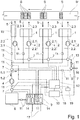
- first embodiment of a device according to the invention are as essential elements processing heads 1, drying devices 2, an exhaust pipe 3, a recirculating air line 6, a catalytic Oxidation unit 8, a sensor unit 10, a control unit 12 and a drying gas line 13 are present.
- the description of the first embodiment of the device according to the invention is based on the assumption that the device is in a normal operating state (continuous operation, no start-up or shut-down phase).
- processing heads 1 are each formed as a printing unit of a printing press. Each processing head 1 applies color of a hue to a material web M guided past the processing heads 1 in the direction of the arrow over predetermined processing periods.
- the substance mixture S applied by each of the processing heads 1 is symbolized as a sequence of differently shaped surfaces.
- the respective color is a substance mixture S which, in addition to color pigments, also contains at least one readily volatile organic solvent.
- the substance mixture S applied to the material web M is at least dried in the region of the respective processing head 1 by means of a drying device 2, wherein in each case a drying device 2 is assigned to a processing head 1.
- the drying device 2 has a drying gas supply line 2.1 for supplying air as a drying gas in the form of a drying gas stream 2.3 to the processing head 1 and for inflating the drying gas stream 2.3 on the material web M. If freshly applied substance mixture S is present on material web M, at least part of the solvent contained in substance mixture S is taken up and removed by the drying gas stream 2.3.
- an exhaust gas outlet 2.2 is provided on the drying device 2, through which the inflated drying gas flow 2.3 can be discharged again as an exhaust gas flow 5 out of the region of the processing head 1.
- the drying gas flow 2.3 in a region of the machining head 1 is inflated onto the material web M in order to dry an applied substance mixture S spatially close to the machining head 1.
- the exhaust gas flow 5 of a dryer 2 is greater than the drying gas stream 2.3 of the same dryer device 2.
- the exhaust gas discharges 2.2 open into an exhaust pipe 3.
- the individual exhaust gas streams 5 of the individual Dryers 2 as a common exhaust stream 5 combined and forwarded.
- a bridge dryer 15 is arranged, which completely spans the material web M.
- the bridge dryer 15 is otherwise constructed and connected as the dryer 2.
- Each drying gas supply 2.1 is in each case assigned a fan 4 for generating the drying gas stream 2.3 and controlled by the control unit 12.
- a fan 4 can be assigned to all or several drying gas supply lines 2.1.
- only one fan 4 may be present, through which the drying gas streams 2.3 are effected in all the drying devices 2. It is possible in further embodiments that fans 4 are exclusively or additionally associated with the exhaust gas outlets 2.2 and / or the exhaust pipe 3.
- a control element 7 is provided, through which the exhaust stream 5 into a first exhaust gas flow share 5.1 and a second exhaust gas flow share 5.2 is divided (each symbolized by arrows).
- the first exhaust gas stream portion 5.1 is passed into a recirculation line 6, which is connected to the drying gas line 13.
- the first exhaust gas stream portion 5.1 of the drying gas line 13 can be fed so that the first exhaust gas stream portion 5.1 the drying equipment 2 again as a drying gas stream 2.3 or as part of which can be fed.
- a fresh air supply 16 is arranged, which is connected via a control element 7 with the circulating air line 6 in connection.
- the first exhaust stream component 5.1 contains a certain proportion during ongoing printing operation of the device, i. a certain concentration, at least one solvent. This fraction is detectable by the sensor unit 10 and by sensors 11 which are signal-technically connected to the sensor unit (not all connections shown for reasons of clarity) and can be provided as the value of the concentration of the solvent. Sensors 11 are arranged in the first embodiment shown in the exhaust pipe 3, in the circulating air line 6 and in the drying gas line 13. Each exhaust outlet 2.2 and the exhaust pipe 3 is associated with a sensor 11, by each of which the concentration of the solvent in the exhaust stream 5 is detected (explosion protection sensors).
- a different number and / or a different arrangement of sensors 11 may be present.
- the second exhaust gas flow component 5.2 passes from the dividing acting control element 7 at the end of the exhaust pipe 3 to a fan 4, which is the fluid catalytic upstream of the catalytic oxidation unit 8. Between the upstream fan 4 and the catalytic oxidation unit 8, a designed as a heat sensor sensor 11 for determining the temperature of the second exhaust gas stream part 5.2 is present.
- the catalytic oxidation unit 8 is provided with a mixed oxide as a material of a catalyst having a space velocity of 8000 h -1 .
- the catalytic oxidation unit 8 takes place in the presence of the catalyst, a thermal reaction of the solvents contained in the second exhaust gas stream 5.2.
- the thermal reaction is exothermic, i. with release of heat energy. If the concentration of the solvent in the second exhaust gas stream portion 5.2 is high enough, the catalytic oxidation unit 8 is operated autothermally.
- the catalytic oxidation unit 8 is followed by a heat exchanger 9, through which the thermally reacted second exhaust gas stream portion 5.2 is passed as clean air.
- the heat exchanger 9 communicates with the circulating air line 6, so that by the action of the heat exchanger 9, the first exhaust gas flow component 5.1 can be heated in a controlled manner.
- sensors 11 for detecting the temperature of the first exhaust gas flow component 5.1 or the thermally converted second exhaust gas flow component 5.2 are present in the circulating air line 6 and after the catalytic oxidation unit.
- a control element 7 assigned to the heat exchanger 9 can be actuated by the control unit 12, by the action of which a quantity of heat transferred to the first exhaust gas flow component 5.1 is controllably adjustable.
- the second exhaust gas flow component 5.2 is discharged to the environment after flowing through the heat exchanger 9 via an exhaust gas discharge 17.
- filter 17 (not shown) may be associated with the further purification of the second exhaust gas stream part 5.2 in further embodiments of the device of the exhaust gas outlet.
- the heat exchanger 9 is connected to a supply line of the second exhaust gas stream part 5.2 to the catalytic oxidation unit 8, so that the temperature of the second exhaust gas stream part 5.2 can be controlled increased before the second exhaust gas stream portion 5.2 of the catalytic oxidation unit 8 is supplied.
- the required heat energy for heating the first exhaust gas flow component 5.1 and / or the second exhaust gas flow component 5.2 is obtained from the second exhaust gas flow component 5.2 leaving the catalytic oxidation unit 8 obtained and transmitted by the heat exchanger 9.
- the heat exchanger 9 has a heating element 14, which is controlled by the control unit 12.
- the heating element 14 consists of two independently controllable heating units (shown in simplified form), so that both the first exhaust gas flow component 5.1 and the second exhaust gas flow component 5.2 are independently heatable.
- the second exhaust gas stream component 5.2 is derived.
- the heated first exhaust gas stream component 5.1 is guided through the circulating air line 6 into the drying gas line 13. From there, the first exhaust gas flow component 5.1 returns to the drying devices 2.
- Fresh air supply 16 can be used to mix fresh air supply with the first exhaust gas flow component 5.1 if necessary.
- control unit 12 By the control unit 12, the drying devices 2, the controller elements 7, the heating elements 14 and the fan 4 can be controlled.
- the control unit 12 is signal-technically connected to the aforementioned elements (some of these compounds are shown by dashed lines).
- the sensor unit 10 receives the signals transmitted by the sensors 11 and uses these to detect the respective values of the temperatures and concentrations.
- the values are provided to the control unit 12.
- the values may be graphed in a further embodiment of the device.
- the temperature and / or concentration values may be displayed on a display of a plant controller.
- the values detected by the sensors 11 are also provided to a control unit 18.
- the control unit 18 is designed as a subunit of the control unit 12 and serves to regulate an O 2 content of the second exhaust gas flow component 5.2.
- at least one sensor 11 for detecting the O 2 content is designed and arranged between the upstream fan 4 and the catalytic oxidation unit 8, so that the O 2 content of the second exhaust gas flow component 5.2 can be measured by this sensor 11.
- the control unit 18 is data-technologically connected to a database 19 in which models are stored, by means of which a control of the O 2 content of the second exhaust gas stream part 5.2 by the control unit 18 takes place.
- a second embodiment of a device according to the invention is shown.
- the elements and their functioning with the in Fig. 1 shown device match.
- a fan 4 is present in the drying gas line 13 through which the drying gas streams 2.3 of all the drying devices 2 are effected.
- a heating element 14 for the controlled heating of the second exhaust gas stream part 5.2 is present between the dividing control element 7 at the end of the exhaust pipe 3 and the upstream of the catalytic oxidation unit 8 fan 4, a heating element 14 for the controlled heating of the second exhaust gas stream part 5.2 is present.
- the heating element 14 is actuated by the control device 12 if the temperature of the second exhaust gas flow component 5.2 is too low for efficient operation of the catalytic oxidation unit 8.
- a heating of the second exhaust gas stream portion 5.2 by means of the heat exchanger 9 is then optional.
- the heating of the second exhaust gas flow component 5.2 by means of the heating element 14 is optional.
- the heat exchanger 9 is only intended to heat if necessary only the second exhaust gas stream part 5.2.
- a heating element 14 upstream of the catalytic oxidation unit 8 is not present, but may be present in further embodiments of the device.
- the recirculation line 6 with the first exhaust gas stream portion 5.1 leads to the dry gas line 13.
- a further heat exchanger 9.1 is arranged, which is equipped with a heating element 14. This heating element 14 is connected to the control unit 12 in connection and can be controlled by this.
- the second exhaust gas stream portion 5.2 is passed as clean air after it has flowed through the heat exchanger 9. Whose heat energy can be transferred wholly or proportionately to the first exhaust gas stream share 5.1.
- a bypass of the further heat exchanger 9.1 is provided, so that the first exhaust gas stream portion 5.1 is then not passed through the other heat exchanger 9.1, when the temperature of the first exhaust gas stream portion 5.1 is above a threshold of 80 ° C here.
- other temperature values may be selected as the threshold value.
- a bypass (not shown) may also be provided on the heat exchanger 9.
- the material web M is guided past the processing heads 1.
- the respective processing heads 1 are activated at predetermined processing periods and a substance mixture S is applied to the material web M by them.
- Each processing head 1 is assigned a substance mixture S in the form of a printing ink.
- the control unit 12 controls the drying device 2 associated with the processing head 1 and puts it into operation. Since the machining heads 1 are basically of the same design, the following description refers, by way of example only, to a machining head 1.
- the fan 4 causes a drying gas flow 2.3 in the drying gas supply line 2.1 and blows it onto the material web M.
- the drying gas stream 2.3 passes over the substance mixture S applied to the material web M by the processing head 1, as a result of which proportionate volatile solvents escaping from the applied substance mixture S are taken up into the drying gas stream 2.3.
- a negative pressure is generated by way of the exhaust gas discharge line 2.2 in that the drying gas stream 2.3 containing the solvent is sucked off as the exhaust gas stream 5.
- the exhaust gas stream 5 passes through the exhaust gas outlet 2.2 in the exhaust pipe 3.
- the concentration of the solvent in the exhaust stream 5 is detected by a sensor 11 as a sensor signal and transmitted to the sensor unit 10. From the sensor signal, a value of the concentration of the solvent is detected and provided to the control unit 12.
- the dividing regulator element 7 is actuated at the end of the exhaust gas line 3 so that the largest part of the exhaust gas stream 5 is conducted into the recirculation air line 6 as first exhaust gas flow component 5.1 , Only the difference between the exhaust gas stream 5 and the drying gas stream 2.3 is fed to the catalytic oxidation unit 8 as the second exhaust gas stream component 5.2.
- the first exhaust gas stream portion 5.1 is fed to the heat exchanger 9 where it is heated and then passed into the drying gas line 13. From there, the first exhaust gas flow component 5.1 is supplied again as a drying gas stream 2.3 corresponding to a further processing period of the processing head 1.
- the drying gas flow 2.3 already contains solvent, but has not yet reached its absorption capacity. As described above, in turn applied substance mixture S is dried, wherein the concentration of the solvent in the exhaust gas stream 5 further increases.
- the dividing regulator element 7 is activated such that the second exhaust gas flow component 5.2 is proportionately increased and the first exhaust gas flow component 5.1 is correspondingly reduced proportionally.
- a drying device 2 is actuated by the control unit 12 whose associated processing head 1 does not undergo any processing period at this time. Additional ambient air, which contains no or only minimal amount of solvent, is sucked into the exhaust gas line 3 via this additionally controlled drying device 2 and the concentration of the solvent in the exhaust gas flow 5 is reduced.
- Such a reduction of the concentration can be triggered as a precaution, if the detected concentration of the solvent is already so high that further drying, for example by supplying a further exhaust stream 5 from a further dryer device 2, to exceed the desired working concentration or a maximum allowable concentration would lead.
- Such a future supply of a further exhaust gas stream 5 may be known since the control unit 12, the predetermined processing periods of the individual processing heads 1 are available and thus a predictive control of the concentration ratios in the device is possible.
- the admixing of ambient air to the exhaust gas stream 5 takes place in such quantities that the second exhaust gas stream component 5.2 has the desired working concentration.
- the temperature of the second exhaust gas flow component 5.2 is detected by means of a sensor 11 and compared with a desired temperature.
- the desired temperature is in a range over which the catalyst of the catalytic oxidation unit 8 operates particularly effectively. If the temperature of the second exhaust gas flow component 5.2 is too low, the control element 7, by which the second exhaust gas flow component 5.2 can be fed to the heat exchanger 9, is controlled by the control unit 12 and the second exhaust gas flow component 5.2 is fed to the heat exchanger 9. In this, the desired temperature of the second exhaust gas flow component 5.2 is set. If the desired temperature of the second exhaust gas flow component 5.2 can not be adjusted by means of the heat exchanger 9 alone, the heating element 14 of the heat exchanger 9 is additionally activated and the second exhaust gas flow component 5.2 is heated accordingly.
- the second exhaust gas flow component 5.2 is thermally converted and the heat energy thereby obtained is used to heat the first and second exhaust gas flow components 5.1 and 5.2 by means of the heat exchanger 9.
- a general model for controlling the O 2 content in the database 19 is stored before the device is put into operation, which is controlled by the control unit 18 is repeatedly retrievable.
- the device is subjected to different operating conditions during a trial operation. In this case, various parameters, such as the solvent concentration, the speed of the fan 4, the achieved working concentration, the O 2 content, temperatures, flow velocities and flow rates, recorded and stored in the form of data sets in the database 19.
- the general model is individually adapted to the specific device and individual models are stored in the database 19. Based on the datasets and individual models, simulations are also performed for scenarios that were not actually tested during trial operation. These simulations are extrapolations of the local / temporal evolution of acquired data series and / or the derivative (here also subsumed under the concept of extrapolation) of fictitious data series and fictitious data sets.
- Both the general model and the individual models are designed in such a way that unwanted overshoots and undershoots of limit values of predetermined parameters are canceled out by control commands of the control unit 18.
- the simulations are used to adapt the individual models such that predicted overshoots and undershoots of limit values do not occur at all.
- collected data series and data records are searched for distinctive data series or striking data records. If such distinctive data series or distinctive data records are found, an individual model is selected which is assigned to these distinctive data series or distinctive data records. If several individual models are associated with the identified distinctive data series or striking data records, the individual model is selected on the basis of the criterion of the greatest correspondence (similarity) of the data with the individual models available for selection.
- the response of the device is again detected and used as a record for adapting the general model or for adapting the individual model used for the control.
- the control of parameters such as the O 2 content is not based on the general model and only when an actual overrun or undercut a threshold, but it will be timely and taking into account the individual reaction (eg inertia) of concrete Device on the basis of a selected individual model control commands given by the control unit 18 to the corresponding controller elements 7.
Landscapes
- Health & Medical Sciences (AREA)
- General Health & Medical Sciences (AREA)
- Toxicology (AREA)
- Engineering & Computer Science (AREA)
- Mechanical Engineering (AREA)
- Drying Of Solid Materials (AREA)
- Exhaust Gas Treatment By Means Of Catalyst (AREA)
- Treatment Of Fiber Materials (AREA)
Claims (9)
- Dispositif d'application de mélanges de substances contenant à chaque fois au moins un solvant organique sur une bande de matériau (M), ayant- un nombre de têtes de traitement (1) pour appliquer à chaque fois un mélange de substances sur les durées de périodes de traitement respectivement prédéterminées sur la bande de matériau (M),- un nombre de dispositifs de séchage (2) pour sécher le mélange de substances appliqué (S) en soufflant un flux de gaz de séchage (2.3) sur le mélange de substances appliqué (S) et en aspirant le flux de gaz de séchage (2.3) chargé de proportions du solvant en tant que flux de gaz d'échappement (5), un dispositif de séchage (2) étant associé à chaque tête de traitement (1),- un système de conduite de gaz ayant à chaque fois une conduite d'alimentation en gaz de séchage (2.1) et une conduite de sortie de gaz d'échappement (2.2) par dispositif de séchage (2) et avec une conduite de gaz d'échappement (3) reliant les dispositifs de séchage (2) et ayant des éléments de réglage (7) commandables pour régler des débits de volume dans les conduites d'alimentation en gaz de séchage (2.1), dans les conduites de sortie de gaz d'échappement (2.2) et dans la conduite de gaz d'échappement (3) et pour diviser de manière contrôlé le flux de gaz d'échappement (5) en une première partie de flux de gaz d'échappement (5.1) et en une deuxième partie de flux de gaz d'échappement (5.2),- une unité de capteur (10) pour détecter et fournir des valeurs d'une concentration de l'au moins un solvant dans le flux de gaz d'échappement (5) en tant que concentration de solvant et- une unité d'oxydation catalytique (8) intégrée pour la conversion thermique du solvant de la deuxième partie de flux de gaz d'échappement (5.2),- une unité de commande (12), par laquelle les éléments de réglage (7) peuvent être commandés individuellement et qui est configurée de sorte qu'un contrôle des éléments de réglage (7) a lieu pour régler une concentration constante de l'au moins un solvant en tant que concentration de travail sur la base d'une comparaison des valeurs de la concentration de solvant avec une gamme de valeurs d'une concentration de travail souhaitée de la deuxième partie de flux de gaz d'échappement (5.2),caractérisé en ce que
une unité de réglage (18) pour régler une concentration en oxygène appelée teneur en O2 dans la deuxième partie de flux de gaz d'échappement (5.2) est présente et l'unité de réglage (18) est en communication de données avec une base de données (19), la base de données (19) étant configurée de telle sorte qu'au moins un modèle général pour régler le teneur en O2 soit stocké dans la base de données (19) de manière à être récupérable de façon répétée, la chute du teneur en O2 de la deuxième partie de flux de gaz d'échappement (5.2) étant évitée ou au moins n'étant autorisée que dans une très faible mesure par ce modèle. - Dispositif selon la revendication 1, caractérisé en ce que l'unité de réglage (18) est partie d'un boucle de régulation aussi incluant au moins un moyen de détection du teneur en O2 actuel.
- Dispositif selon la revendication 2, caractérisé en ce que le moyen de détection du teneur en O2 actuel est un capteur d'oxygène disposé à une entrée de l'unité d'oxydation catalytique (8).
- Dispositif selon une des revendications précédentes, caractérisé en ce que, au moyen de l'unité de commande (12), au moins un dispositif de séchage (2) est commandable en plus en dehors de sa période de traitement prédéterminée, lorsqu'une concentration de gaz d'échappement est détectée qui est supérieure à la concentration de travail ou à la concentration autorisée, et, par commande du dispositif de séchage (2), de l'air frais est fourni de l'environnement du dispositif de séchage (2) commandé en dehors de sa période de traitement prédéterminée et peut être ajouté au flux de gaz d'échappement (5).
- Dispositif selon une des revendications précédentes, caractérisé en ce que l'unité d'oxydation catalytique (8) contient un matériau catalytique de la classe de perovskites pour la conversion thermique du solvant de la deuxième partie de flux de gaz d'échappement (5.2).
- Dispositif selon une des revendications précédentes, caractérisé en ce que l'unité d'oxydation catalytique (8) est une unité opérée de manière autothermique après une phase initiale.
- Dispositif selon une des revendications précédentes, caractérisé en ce que l'unité d'oxydation catalytique (8) est associée avec un échangeur de chaleur (9), par lequel une énergie thermique qui est libérée lors de la conversion thermique est transférable proportionnellement à la première partie de flux de gaz d'échappement (5.1) et à la deuxième partie de flux de gaz d'échappement (5.2).
- Procédé pour fournir une concentration de travail constante d'au moins un solvant organique dans une proportion d'un flux de gaz d'échappement (5) pour une unité d'oxydation catalytique (8) intégrée d'un dispositif d'application de mélanges de substances contenant à chaque fois au moins un solvant organique sur une bande de matériau (M) avec les étapes:- souffler un flux de gaz de séchage (2.3) sur un mélange de substances (S) appliqué sur la bande de matériau (M),- aspirer le flux de gaz de séchage (2.3) chargé de proportions du solvant en tant que flux de gaz d'échappement (5),- détecter une concentration de l'au moins un solvant dans le flux de gaz d'échappement (5) en tant que concentration de solvant,- comparer des valeurs de la concentration de solvant comme valeurs réelles avec la valeur d'une concentration de travail souhaitée comme valeur cible,- régler une concentration de solvant constante en tant que concentration de travail en réglant une proportion du flux de gaz d'échappement (5) du flux de gaz de séchage (2.3),- diviser le flux de gaz d'échappement (5) en une première partie de flux de gaz d'échappement (5.1) et en une deuxième partie de flux de gaz d'échappement (5.2) et conduire la deuxième partie de flux de gaz d'échappement (5.2) vers une unité d'oxydation catalytique (8) pour la conversion thermique du solvant contenu dans la deuxième partie de flux de gaz d'échappement (5.2) et- régler une concentration en oxygène appelée teneur en O2 de la deuxième partie de flux de gaz d'échappement (5.2) sur la base d'un modèle de sorte qu'une chute du teneur en O2 de la deuxième partie de flux de gaz d'échappement (5.2) soit évitée ou au moins ne soit autorisée que dans une très faible mesure.
- Procédé selon la revendication 8, caractérisé en ce que le réglage de la concentration en oxygène est effectué par une alimentation commandée en air frais.
Applications Claiming Priority (1)
| Application Number | Priority Date | Filing Date | Title |
|---|---|---|---|
| DE102013108054.5A DE102013108054A1 (de) | 2013-07-26 | 2013-07-26 | Vorrichtung zum Aufbringen von Stoffgemischen auf eine Materialbahn und Verfahren zur Reinigung von Abgasen der Vorrichtung |
Publications (3)
| Publication Number | Publication Date |
|---|---|
| EP2829403A2 EP2829403A2 (fr) | 2015-01-28 |
| EP2829403A3 EP2829403A3 (fr) | 2015-09-23 |
| EP2829403B1 true EP2829403B1 (fr) | 2019-10-23 |
Family
ID=51224762
Family Applications (1)
| Application Number | Title | Priority Date | Filing Date |
|---|---|---|---|
| EP14178154.2A Active EP2829403B1 (fr) | 2013-07-26 | 2014-07-23 | Dispositif d'application de mélanges de matières à concentration constante sur une bande de matériau et procédé de nettoyage des gaz d'échappement du dispositif |
Country Status (2)
| Country | Link |
|---|---|
| EP (1) | EP2829403B1 (fr) |
| DE (1) | DE102013108054A1 (fr) |
Families Citing this family (4)
| Publication number | Priority date | Publication date | Assignee | Title |
|---|---|---|---|---|
| EP3967495A1 (fr) * | 2020-09-10 | 2022-03-16 | Hubergroup Deutschland GmbH | Système et procédé de commande pour machines d'impression permettant de régler et de surveiller les paramètres relatifs au séchage, à la migration et/ou à la réticulation |
| AR130319A1 (es) * | 2022-09-28 | 2024-11-27 | Uteco Converting Spa | Sistema de impresión |
| DE102023114321B3 (de) * | 2023-05-31 | 2024-06-20 | Gunther Ackermann | Umluft-Prozess-System |
| DE102024107273A1 (de) * | 2024-03-14 | 2025-09-04 | Canon Production Printing Holding B.V. | Druckvorrichtung mit zentraler Abgasreinigung |
Family Cites Families (12)
| Publication number | Priority date | Publication date | Assignee | Title |
|---|---|---|---|---|
| GB2022801A (en) * | 1978-06-01 | 1979-12-19 | Bebst Sa | An Energy Recovery System for Use on a Printing Press or the Like |
| DE2948603C2 (de) | 1979-12-03 | 1986-05-22 | Pohl, Hans Christoph, Dr.-Ing., 5810 Witten | Verfahren zur Abfuhr von brennbaren Lösungsmitteln aus einer Trocknungsanlage |
| DE3120738A1 (de) | 1981-05-25 | 1982-12-09 | Windmöller & Hölscher, 4540 Lengerich | Verfahren und vorrichtung zum trocknen von bedruckten oder beschichteten bahnen. |
| JPS58175662A (ja) * | 1982-04-09 | 1983-10-14 | Toshiba Mach Co Ltd | 印刷機の脱臭装置付き乾燥炉 |
| DE19505971C5 (de) * | 1995-02-21 | 2013-03-14 | Windmöller & Hölscher Kg | Vorrichtung zum Trocknen von bedruckten oder beschichteten Bahnen |
| DE19755812B4 (de) | 1997-12-16 | 2009-01-02 | Giko Verpackungen Gmbh | Verfahren und Vorrichtung zur Regelung der Luftbeladung |
| DE10357559A1 (de) | 2003-10-24 | 2005-06-16 | Reinluft-Relox Gmbh | Verfahren und Vorrichtung zum Trocknen von bedruckten lösungsmittelhaltigen Materialien, insbesondere Materialbahnen, sowie katalytische Nachverbrennungsanlage zum Reinigen eines lösungsmittelhaltigen Mediums |
| DE102004040131B4 (de) * | 2004-08-18 | 2008-02-21 | Relox Gmbh | Verfahren und Vorrichtung zur Trocknung von bahnförmigem Material mit einer integrierten katalytischen Verbrennung der Schadstoffe |
| DE102010026604A1 (de) * | 2010-07-09 | 2012-01-12 | Heidelberger Druckmaschinen Ag | Bogenverarbeitende Maschine mit einem oder mehreren Trocknern |
| JP5691327B2 (ja) * | 2010-09-14 | 2015-04-01 | セイコーエプソン株式会社 | 記録装置及び記録装置の制御方法 |
| DE102010062145B4 (de) * | 2010-11-29 | 2015-10-29 | Koenig & Bauer Ag | Druckmaschine mit mindestens einem einen Heißlufttrockner aufweisenden Trocknersystem sowie Verfahren zum Betrieb einer Druckmaschine mit mindestens einem Heißlufttrockner |
| GB201220912D0 (en) | 2012-11-21 | 2013-01-02 | Johnson Matthey Plc | Oxidation catalyst for treating the exhaust gas of a compression ignition engine |
-
2013
- 2013-07-26 DE DE102013108054.5A patent/DE102013108054A1/de not_active Ceased
-
2014
- 2014-07-23 EP EP14178154.2A patent/EP2829403B1/fr active Active
Non-Patent Citations (1)
| Title |
|---|
| None * |
Also Published As
| Publication number | Publication date |
|---|---|
| EP2829403A3 (fr) | 2015-09-23 |
| EP2829403A2 (fr) | 2015-01-28 |
| DE102013108054A1 (de) | 2015-01-29 |
Similar Documents
| Publication | Publication Date | Title |
|---|---|---|
| EP3332201B1 (fr) | Installation pour le traitement de pièces et opération d'une installation | |
| DE69920684T2 (de) | Warenbahntrockner mit völlig integrierter regenerativer heizquelle | |
| EP3356753B1 (fr) | Dipositif pour le conditionnement thermique d' objets, particulièrement pour secher des carrosseries de véhicule recouvertes | |
| EP2783177B1 (fr) | Dispositif de mise en température d'objets | |
| EP2829403A2 (fr) | Dispositif d'application de mélanges de matières à concentration constante sur une bande de matériau et procédé de nettoyage des gaz d'échappement du dispositif | |
| DE2819814A1 (de) | Verfahren und einrichtung zur entfernung von loesungsmitteln aus den abgasen insbesondere einer mit tiefdruckzylindern arbeitenden druck- oder verpackungspresse | |
| DE102011075109A1 (de) | Thermoluft-Trocknungseinrichtung mit Abwärmenutzung | |
| EP0065783A1 (fr) | Dispositif pour sécher des bandes imprimées dans une machine à imprimer | |
| EP2924380B1 (fr) | Brûleur supplémentaire | |
| EP1142711A1 (fr) | Commande d'un système de séchage d'une machine d'impression | |
| DE10349090A1 (de) | Anlage und Verfahren zum Trocknen von Gegenständen | |
| DE3118830C2 (de) | "Anlage zur Lackdrahtherstellung im Inlineverfahren" | |
| DE10039495A1 (de) | Anlage zur Behandlung von Gegenständen | |
| EP3535526B1 (fr) | Procédé de purification d'air évacué et dispositif de purification d'air évacué | |
| EP0489962A1 (fr) | Méthode et dispositif pour imprégner et/ou revêtir des objets | |
| DE102010009520B4 (de) | Offsetdruckmaschine und Verfahren zum Betreiben einer Offsetdruckmaschine | |
| DE8711112U1 (de) | Katalytische Nachverbrennungsvorrichtung | |
| DE10357559A1 (de) | Verfahren und Vorrichtung zum Trocknen von bedruckten lösungsmittelhaltigen Materialien, insbesondere Materialbahnen, sowie katalytische Nachverbrennungsanlage zum Reinigen eines lösungsmittelhaltigen Mediums | |
| DE102014111465A1 (de) | Sensorlose Funktionsüberwachung der Trocknung durch Plausibilitätsüberwachung der Leistungsaufnahme | |
| DE102012100876B4 (de) | Verfahren zum Betreiben einer Umluftkreisanordnung | |
| EP2361358B1 (fr) | Procédé et dispositif de postcombustion thermique d'air évacué, chargé de substances oxydables | |
| DE60317789T2 (de) | Vorrichtung und verfahren zur thermischen reinigung und trennung von metallteilen | |
| EP2354740A2 (fr) | Dispositif et procédé de traitement thermique de bandes de produits en forme de bandes | |
| DE4207071A1 (de) | Regelsystem fuer rollenrotationsdruckmaschinen | |
| DE19914551C2 (de) | Vorrichtung zur kontrollierten Emissionsreduzierung von Durchlauftrocknern in Druck- oder Beschichtungsanlagen |
Legal Events
| Date | Code | Title | Description |
|---|---|---|---|
| 17P | Request for examination filed |
Effective date: 20140723 |
|
| AK | Designated contracting states |
Kind code of ref document: A2 Designated state(s): AL AT BE BG CH CY CZ DE DK EE ES FI FR GB GR HR HU IE IS IT LI LT LU LV MC MK MT NL NO PL PT RO RS SE SI SK SM TR |
|
| AX | Request for extension of the european patent |
Extension state: BA ME |
|
| PUAI | Public reference made under article 153(3) epc to a published international application that has entered the european phase |
Free format text: ORIGINAL CODE: 0009012 |
|
| PUAL | Search report despatched |
Free format text: ORIGINAL CODE: 0009013 |
|
| AK | Designated contracting states |
Kind code of ref document: A3 Designated state(s): AL AT BE BG CH CY CZ DE DK EE ES FI FR GB GR HR HU IE IS IT LI LT LU LV MC MK MT NL NO PL PT RO RS SE SI SK SM TR |
|
| AX | Request for extension of the european patent |
Extension state: BA ME |
|
| RIC1 | Information provided on ipc code assigned before grant |
Ipc: B41J 11/00 20060101ALI20150820BHEP Ipc: B05C 9/00 20060101ALI20150820BHEP Ipc: B41F 5/24 20060101ALI20150820BHEP Ipc: B41J 29/00 20060101ALI20150820BHEP Ipc: B41F 23/04 20060101ALI20150820BHEP Ipc: B41F 31/02 20060101AFI20150820BHEP Ipc: B41J 2/17 20060101ALI20150820BHEP |
|
| R17P | Request for examination filed (corrected) |
Effective date: 20160202 |
|
| RBV | Designated contracting states (corrected) |
Designated state(s): AL AT BE BG CH CY CZ DE DK EE ES FI FR GB GR HR HU IE IS IT LI LT LU LV MC MK MT NL NO PL PT RO RS SE SI SK SM TR |
|
| RAP1 | Party data changed (applicant data changed or rights of an application transferred) |
Owner name: JENOPTIK AUTOMATISIERUNGSTECHNIK GMBH |
|
| STAA | Information on the status of an ep patent application or granted ep patent |
Free format text: STATUS: EXAMINATION IS IN PROGRESS |
|
| 17Q | First examination report despatched |
Effective date: 20180813 |
|
| GRAP | Despatch of communication of intention to grant a patent |
Free format text: ORIGINAL CODE: EPIDOSNIGR1 |
|
| STAA | Information on the status of an ep patent application or granted ep patent |
Free format text: STATUS: GRANT OF PATENT IS INTENDED |
|
| INTG | Intention to grant announced |
Effective date: 20190516 |
|
| GRAS | Grant fee paid |
Free format text: ORIGINAL CODE: EPIDOSNIGR3 |
|
| GRAA | (expected) grant |
Free format text: ORIGINAL CODE: 0009210 |
|
| STAA | Information on the status of an ep patent application or granted ep patent |
Free format text: STATUS: THE PATENT HAS BEEN GRANTED |
|
| AK | Designated contracting states |
Kind code of ref document: B1 Designated state(s): AL AT BE BG CH CY CZ DE DK EE ES FI FR GB GR HR HU IE IS IT LI LT LU LV MC MK MT NL NO PL PT RO RS SE SI SK SM TR |
|
| REG | Reference to a national code |
Ref country code: GB Ref legal event code: FG4D Free format text: NOT ENGLISH |
|
| REG | Reference to a national code |
Ref country code: CH Ref legal event code: EP |
|
| REG | Reference to a national code |
Ref country code: IE Ref legal event code: FG4D Free format text: LANGUAGE OF EP DOCUMENT: GERMAN |
|
| REG | Reference to a national code |
Ref country code: DE Ref legal event code: R096 Ref document number: 502014012896 Country of ref document: DE |
|
| REG | Reference to a national code |
Ref country code: AT Ref legal event code: REF Ref document number: 1193211 Country of ref document: AT Kind code of ref document: T Effective date: 20191115 |
|
| REG | Reference to a national code |
Ref country code: NL Ref legal event code: MP Effective date: 20191023 |
|
| REG | Reference to a national code |
Ref country code: LT Ref legal event code: MG4D |
|
| PG25 | Lapsed in a contracting state [announced via postgrant information from national office to epo] |
Ref country code: LT Free format text: LAPSE BECAUSE OF FAILURE TO SUBMIT A TRANSLATION OF THE DESCRIPTION OR TO PAY THE FEE WITHIN THE PRESCRIBED TIME-LIMIT Effective date: 20191023 Ref country code: GR Free format text: LAPSE BECAUSE OF FAILURE TO SUBMIT A TRANSLATION OF THE DESCRIPTION OR TO PAY THE FEE WITHIN THE PRESCRIBED TIME-LIMIT Effective date: 20200124 Ref country code: PL Free format text: LAPSE BECAUSE OF FAILURE TO SUBMIT A TRANSLATION OF THE DESCRIPTION OR TO PAY THE FEE WITHIN THE PRESCRIBED TIME-LIMIT Effective date: 20191023 Ref country code: NL Free format text: LAPSE BECAUSE OF FAILURE TO SUBMIT A TRANSLATION OF THE DESCRIPTION OR TO PAY THE FEE WITHIN THE PRESCRIBED TIME-LIMIT Effective date: 20191023 Ref country code: BG Free format text: LAPSE BECAUSE OF FAILURE TO SUBMIT A TRANSLATION OF THE DESCRIPTION OR TO PAY THE FEE WITHIN THE PRESCRIBED TIME-LIMIT Effective date: 20200123 Ref country code: PT Free format text: LAPSE BECAUSE OF FAILURE TO SUBMIT A TRANSLATION OF THE DESCRIPTION OR TO PAY THE FEE WITHIN THE PRESCRIBED TIME-LIMIT Effective date: 20200224 Ref country code: ES Free format text: LAPSE BECAUSE OF FAILURE TO SUBMIT A TRANSLATION OF THE DESCRIPTION OR TO PAY THE FEE WITHIN THE PRESCRIBED TIME-LIMIT Effective date: 20191023 Ref country code: FI Free format text: LAPSE BECAUSE OF FAILURE TO SUBMIT A TRANSLATION OF THE DESCRIPTION OR TO PAY THE FEE WITHIN THE PRESCRIBED TIME-LIMIT Effective date: 20191023 Ref country code: SE Free format text: LAPSE BECAUSE OF FAILURE TO SUBMIT A TRANSLATION OF THE DESCRIPTION OR TO PAY THE FEE WITHIN THE PRESCRIBED TIME-LIMIT Effective date: 20191023 Ref country code: LV Free format text: LAPSE BECAUSE OF FAILURE TO SUBMIT A TRANSLATION OF THE DESCRIPTION OR TO PAY THE FEE WITHIN THE PRESCRIBED TIME-LIMIT Effective date: 20191023 Ref country code: NO Free format text: LAPSE BECAUSE OF FAILURE TO SUBMIT A TRANSLATION OF THE DESCRIPTION OR TO PAY THE FEE WITHIN THE PRESCRIBED TIME-LIMIT Effective date: 20200123 |
|
| PG25 | Lapsed in a contracting state [announced via postgrant information from national office to epo] |
Ref country code: HR Free format text: LAPSE BECAUSE OF FAILURE TO SUBMIT A TRANSLATION OF THE DESCRIPTION OR TO PAY THE FEE WITHIN THE PRESCRIBED TIME-LIMIT Effective date: 20191023 Ref country code: RS Free format text: LAPSE BECAUSE OF FAILURE TO SUBMIT A TRANSLATION OF THE DESCRIPTION OR TO PAY THE FEE WITHIN THE PRESCRIBED TIME-LIMIT Effective date: 20191023 Ref country code: IS Free format text: LAPSE BECAUSE OF FAILURE TO SUBMIT A TRANSLATION OF THE DESCRIPTION OR TO PAY THE FEE WITHIN THE PRESCRIBED TIME-LIMIT Effective date: 20200224 |
|
| PG25 | Lapsed in a contracting state [announced via postgrant information from national office to epo] |
Ref country code: AL Free format text: LAPSE BECAUSE OF FAILURE TO SUBMIT A TRANSLATION OF THE DESCRIPTION OR TO PAY THE FEE WITHIN THE PRESCRIBED TIME-LIMIT Effective date: 20191023 |
|
| REG | Reference to a national code |
Ref country code: DE Ref legal event code: R097 Ref document number: 502014012896 Country of ref document: DE |
|
| PG2D | Information on lapse in contracting state deleted |
Ref country code: IS |
|
| PG25 | Lapsed in a contracting state [announced via postgrant information from national office to epo] |
Ref country code: CZ Free format text: LAPSE BECAUSE OF FAILURE TO SUBMIT A TRANSLATION OF THE DESCRIPTION OR TO PAY THE FEE WITHIN THE PRESCRIBED TIME-LIMIT Effective date: 20191023 Ref country code: EE Free format text: LAPSE BECAUSE OF FAILURE TO SUBMIT A TRANSLATION OF THE DESCRIPTION OR TO PAY THE FEE WITHIN THE PRESCRIBED TIME-LIMIT Effective date: 20191023 Ref country code: RO Free format text: LAPSE BECAUSE OF FAILURE TO SUBMIT A TRANSLATION OF THE DESCRIPTION OR TO PAY THE FEE WITHIN THE PRESCRIBED TIME-LIMIT Effective date: 20191023 Ref country code: DK Free format text: LAPSE BECAUSE OF FAILURE TO SUBMIT A TRANSLATION OF THE DESCRIPTION OR TO PAY THE FEE WITHIN THE PRESCRIBED TIME-LIMIT Effective date: 20191023 Ref country code: IS Free format text: LAPSE BECAUSE OF FAILURE TO SUBMIT A TRANSLATION OF THE DESCRIPTION OR TO PAY THE FEE WITHIN THE PRESCRIBED TIME-LIMIT Effective date: 20200223 |
|
| PLBE | No opposition filed within time limit |
Free format text: ORIGINAL CODE: 0009261 |
|
| STAA | Information on the status of an ep patent application or granted ep patent |
Free format text: STATUS: NO OPPOSITION FILED WITHIN TIME LIMIT |
|
| PG25 | Lapsed in a contracting state [announced via postgrant information from national office to epo] |
Ref country code: SK Free format text: LAPSE BECAUSE OF FAILURE TO SUBMIT A TRANSLATION OF THE DESCRIPTION OR TO PAY THE FEE WITHIN THE PRESCRIBED TIME-LIMIT Effective date: 20191023 Ref country code: IT Free format text: LAPSE BECAUSE OF FAILURE TO SUBMIT A TRANSLATION OF THE DESCRIPTION OR TO PAY THE FEE WITHIN THE PRESCRIBED TIME-LIMIT Effective date: 20191023 Ref country code: SM Free format text: LAPSE BECAUSE OF FAILURE TO SUBMIT A TRANSLATION OF THE DESCRIPTION OR TO PAY THE FEE WITHIN THE PRESCRIBED TIME-LIMIT Effective date: 20191023 |
|
| 26N | No opposition filed |
Effective date: 20200724 |
|
| REG | Reference to a national code |
Ref country code: DE Ref legal event code: R082 Ref document number: 502014012896 Country of ref document: DE Representative=s name: GLEIM PETRI OEHMKE PATENT- UND RECHTSANWALTSPA, DE |
|
| PG25 | Lapsed in a contracting state [announced via postgrant information from national office to epo] |
Ref country code: SI Free format text: LAPSE BECAUSE OF FAILURE TO SUBMIT A TRANSLATION OF THE DESCRIPTION OR TO PAY THE FEE WITHIN THE PRESCRIBED TIME-LIMIT Effective date: 20191023 |
|
| PG25 | Lapsed in a contracting state [announced via postgrant information from national office to epo] |
Ref country code: MC Free format text: LAPSE BECAUSE OF FAILURE TO SUBMIT A TRANSLATION OF THE DESCRIPTION OR TO PAY THE FEE WITHIN THE PRESCRIBED TIME-LIMIT Effective date: 20191023 |
|
| REG | Reference to a national code |
Ref country code: CH Ref legal event code: PL |
|
| GBPC | Gb: european patent ceased through non-payment of renewal fee |
Effective date: 20200723 |
|
| REG | Reference to a national code |
Ref country code: BE Ref legal event code: MM Effective date: 20200731 |
|
| PG25 | Lapsed in a contracting state [announced via postgrant information from national office to epo] |
Ref country code: GB Free format text: LAPSE BECAUSE OF NON-PAYMENT OF DUE FEES Effective date: 20200723 Ref country code: LI Free format text: LAPSE BECAUSE OF NON-PAYMENT OF DUE FEES Effective date: 20200731 Ref country code: CH Free format text: LAPSE BECAUSE OF NON-PAYMENT OF DUE FEES Effective date: 20200731 Ref country code: LU Free format text: LAPSE BECAUSE OF NON-PAYMENT OF DUE FEES Effective date: 20200723 Ref country code: FR Free format text: LAPSE BECAUSE OF NON-PAYMENT OF DUE FEES Effective date: 20200731 |
|
| PG25 | Lapsed in a contracting state [announced via postgrant information from national office to epo] |
Ref country code: BE Free format text: LAPSE BECAUSE OF NON-PAYMENT OF DUE FEES Effective date: 20200731 |
|
| PG25 | Lapsed in a contracting state [announced via postgrant information from national office to epo] |
Ref country code: IE Free format text: LAPSE BECAUSE OF NON-PAYMENT OF DUE FEES Effective date: 20200723 |
|
| REG | Reference to a national code |
Ref country code: AT Ref legal event code: MM01 Ref document number: 1193211 Country of ref document: AT Kind code of ref document: T Effective date: 20200723 |
|
| PG25 | Lapsed in a contracting state [announced via postgrant information from national office to epo] |
Ref country code: AT Free format text: LAPSE BECAUSE OF NON-PAYMENT OF DUE FEES Effective date: 20200723 |
|
| PGFP | Annual fee paid to national office [announced via postgrant information from national office to epo] |
Ref country code: DE Payment date: 20210721 Year of fee payment: 8 |
|
| PG25 | Lapsed in a contracting state [announced via postgrant information from national office to epo] |
Ref country code: TR Free format text: LAPSE BECAUSE OF FAILURE TO SUBMIT A TRANSLATION OF THE DESCRIPTION OR TO PAY THE FEE WITHIN THE PRESCRIBED TIME-LIMIT Effective date: 20191023 Ref country code: MT Free format text: LAPSE BECAUSE OF FAILURE TO SUBMIT A TRANSLATION OF THE DESCRIPTION OR TO PAY THE FEE WITHIN THE PRESCRIBED TIME-LIMIT Effective date: 20191023 Ref country code: CY Free format text: LAPSE BECAUSE OF FAILURE TO SUBMIT A TRANSLATION OF THE DESCRIPTION OR TO PAY THE FEE WITHIN THE PRESCRIBED TIME-LIMIT Effective date: 20191023 |
|
| PG25 | Lapsed in a contracting state [announced via postgrant information from national office to epo] |
Ref country code: MK Free format text: LAPSE BECAUSE OF FAILURE TO SUBMIT A TRANSLATION OF THE DESCRIPTION OR TO PAY THE FEE WITHIN THE PRESCRIBED TIME-LIMIT Effective date: 20191023 |
|
| REG | Reference to a national code |
Ref country code: DE Ref legal event code: R119 Ref document number: 502014012896 Country of ref document: DE |
|
| PG25 | Lapsed in a contracting state [announced via postgrant information from national office to epo] |
Ref country code: DE Free format text: LAPSE BECAUSE OF NON-PAYMENT OF DUE FEES Effective date: 20230201 |