EP2829403B1 - Device for applying substance mixtures having a constant concentration onto a material web and method of cleaning waste gases from the device - Google Patents
Device for applying substance mixtures having a constant concentration onto a material web and method of cleaning waste gases from the device Download PDFInfo
- Publication number
- EP2829403B1 EP2829403B1 EP14178154.2A EP14178154A EP2829403B1 EP 2829403 B1 EP2829403 B1 EP 2829403B1 EP 14178154 A EP14178154 A EP 14178154A EP 2829403 B1 EP2829403 B1 EP 2829403B1
- Authority
- EP
- European Patent Office
- Prior art keywords
- exhaust gas
- gas flow
- drying
- solvent
- concentration
- Prior art date
- Legal status (The legal status is an assumption and is not a legal conclusion. Google has not performed a legal analysis and makes no representation as to the accuracy of the status listed.)
- Active
Links
- 239000000463 material Substances 0.000 title claims description 55
- 239000000203 mixture Substances 0.000 title claims description 51
- 239000000126 substance Substances 0.000 title claims description 36
- 238000000034 method Methods 0.000 title claims description 21
- 238000004140 cleaning Methods 0.000 title description 2
- 239000002912 waste gas Substances 0.000 title 1
- 239000007789 gas Substances 0.000 claims description 300
- 238000001035 drying Methods 0.000 claims description 135
- 239000002904 solvent Substances 0.000 claims description 87
- 230000003197 catalytic effect Effects 0.000 claims description 77
- 238000007254 oxidation reaction Methods 0.000 claims description 77
- 230000003647 oxidation Effects 0.000 claims description 76
- 238000012545 processing Methods 0.000 claims description 54
- 239000003054 catalyst Substances 0.000 claims description 29
- 238000006243 chemical reaction Methods 0.000 claims description 24
- 230000001105 regulatory effect Effects 0.000 claims description 16
- QVGXLLKOCUKJST-UHFFFAOYSA-N atomic oxygen Chemical compound [O] QVGXLLKOCUKJST-UHFFFAOYSA-N 0.000 claims description 13
- 239000003960 organic solvent Substances 0.000 claims description 13
- 239000001301 oxygen Substances 0.000 claims description 13
- 229910052760 oxygen Inorganic materials 0.000 claims description 13
- 230000033228 biological regulation Effects 0.000 claims description 5
- 238000007664 blowing Methods 0.000 claims description 3
- 238000004891 communication Methods 0.000 claims 1
- 239000003570 air Substances 0.000 description 44
- 238000010438 heat treatment Methods 0.000 description 33
- LFQSCWFLJHTTHZ-UHFFFAOYSA-N Ethanol Chemical compound CCO LFQSCWFLJHTTHZ-UHFFFAOYSA-N 0.000 description 16
- 238000007639 printing Methods 0.000 description 14
- 230000001276 controlling effect Effects 0.000 description 8
- 230000008569 process Effects 0.000 description 8
- 238000003754 machining Methods 0.000 description 7
- XEKOWRVHYACXOJ-UHFFFAOYSA-N Ethyl acetate Chemical compound CCOC(C)=O XEKOWRVHYACXOJ-UHFFFAOYSA-N 0.000 description 6
- 238000013461 design Methods 0.000 description 6
- 238000004880 explosion Methods 0.000 description 6
- 238000011144 upstream manufacturing Methods 0.000 description 6
- 230000000694 effects Effects 0.000 description 5
- 238000010586 diagram Methods 0.000 description 4
- 239000003344 environmental pollutant Substances 0.000 description 4
- 230000002349 favourable effect Effects 0.000 description 4
- 231100000719 pollutant Toxicity 0.000 description 4
- 230000005855 radiation Effects 0.000 description 4
- 230000009467 reduction Effects 0.000 description 4
- OKKJLVBELUTLKV-UHFFFAOYSA-N Methanol Chemical compound OC OKKJLVBELUTLKV-UHFFFAOYSA-N 0.000 description 3
- 238000010521 absorption reaction Methods 0.000 description 3
- 230000009471 action Effects 0.000 description 3
- 230000008901 benefit Effects 0.000 description 3
- 238000006555 catalytic reaction Methods 0.000 description 3
- 238000000576 coating method Methods 0.000 description 3
- 238000002485 combustion reaction Methods 0.000 description 3
- 230000007613 environmental effect Effects 0.000 description 3
- 229910000510 noble metal Inorganic materials 0.000 description 3
- 230000001590 oxidative effect Effects 0.000 description 3
- 239000003973 paint Substances 0.000 description 3
- 230000004044 response Effects 0.000 description 3
- 238000004088 simulation Methods 0.000 description 3
- 239000012855 volatile organic compound Substances 0.000 description 3
- CSCPPACGZOOCGX-UHFFFAOYSA-N Acetone Chemical compound CC(C)=O CSCPPACGZOOCGX-UHFFFAOYSA-N 0.000 description 2
- UGFAIRIUMAVXCW-UHFFFAOYSA-N Carbon monoxide Chemical compound [O+]#[C-] UGFAIRIUMAVXCW-UHFFFAOYSA-N 0.000 description 2
- MYMOFIZGZYHOMD-UHFFFAOYSA-N Dioxygen Chemical compound O=O MYMOFIZGZYHOMD-UHFFFAOYSA-N 0.000 description 2
- KFZMGEQAYNKOFK-UHFFFAOYSA-N Isopropanol Chemical compound CC(C)O KFZMGEQAYNKOFK-UHFFFAOYSA-N 0.000 description 2
- 230000004913 activation Effects 0.000 description 2
- 239000012080 ambient air Substances 0.000 description 2
- 239000011248 coating agent Substances 0.000 description 2
- 150000001875 compounds Chemical class 0.000 description 2
- 238000000354 decomposition reaction Methods 0.000 description 2
- 238000011161 development Methods 0.000 description 2
- 230000018109 developmental process Effects 0.000 description 2
- 238000001704 evaporation Methods 0.000 description 2
- 230000008020 evaporation Effects 0.000 description 2
- 238000013213 extrapolation Methods 0.000 description 2
- 239000003546 flue gas Substances 0.000 description 2
- 238000004519 manufacturing process Methods 0.000 description 2
- 229910044991 metal oxide Inorganic materials 0.000 description 2
- 229910003455 mixed metal oxide Inorganic materials 0.000 description 2
- 238000002156 mixing Methods 0.000 description 2
- VLKZOEOYAKHREP-UHFFFAOYSA-N n-Hexane Chemical compound CCCCCC VLKZOEOYAKHREP-UHFFFAOYSA-N 0.000 description 2
- 125000004430 oxygen atom Chemical group O* 0.000 description 2
- 230000036961 partial effect Effects 0.000 description 2
- 239000004033 plastic Substances 0.000 description 2
- 229920003023 plastic Polymers 0.000 description 2
- 238000000746 purification Methods 0.000 description 2
- 230000003134 recirculating effect Effects 0.000 description 2
- 229920006395 saturated elastomer Polymers 0.000 description 2
- -1 sheets Substances 0.000 description 2
- 239000007921 spray Substances 0.000 description 2
- 239000002023 wood Substances 0.000 description 2
- 230000002411 adverse Effects 0.000 description 1
- 238000005273 aeration Methods 0.000 description 1
- 125000004429 atom Chemical group 0.000 description 1
- BTANRVKWQNVYAZ-UHFFFAOYSA-N butan-2-ol Chemical compound CCC(C)O BTANRVKWQNVYAZ-UHFFFAOYSA-N 0.000 description 1
- 238000004364 calculation method Methods 0.000 description 1
- 239000000969 carrier Substances 0.000 description 1
- 230000015556 catabolic process Effects 0.000 description 1
- 239000011093 chipboard Substances 0.000 description 1
- 239000000567 combustion gas Substances 0.000 description 1
- 230000000295 complement effect Effects 0.000 description 1
- 239000002131 composite material Substances 0.000 description 1
- 239000000470 constituent Substances 0.000 description 1
- 238000001816 cooling Methods 0.000 description 1
- 230000007423 decrease Effects 0.000 description 1
- 238000006731 degradation reaction Methods 0.000 description 1
- 230000001419 dependent effect Effects 0.000 description 1
- 229910001882 dioxygen Inorganic materials 0.000 description 1
- 239000002270 dispersing agent Substances 0.000 description 1
- 238000011156 evaluation Methods 0.000 description 1
- 239000002360 explosive Substances 0.000 description 1
- 239000010408 film Substances 0.000 description 1
- 239000012530 fluid Substances 0.000 description 1
- 239000011521 glass Substances 0.000 description 1
- 239000004922 lacquer Substances 0.000 description 1
- 239000007788 liquid Substances 0.000 description 1
- 238000013178 mathematical model Methods 0.000 description 1
- 238000005259 measurement Methods 0.000 description 1
- 229910052751 metal Inorganic materials 0.000 description 1
- 239000002184 metal Substances 0.000 description 1
- 150000004706 metal oxides Chemical class 0.000 description 1
- 238000012821 model calculation Methods 0.000 description 1
- 239000005022 packaging material Substances 0.000 description 1
- 238000010422 painting Methods 0.000 description 1
- 239000000123 paper Substances 0.000 description 1
- AQIXEPGDORPWBJ-UHFFFAOYSA-N pentan-3-ol Chemical compound CCC(O)CC AQIXEPGDORPWBJ-UHFFFAOYSA-N 0.000 description 1
- 239000000049 pigment Substances 0.000 description 1
- 239000004014 plasticizer Substances 0.000 description 1
- 239000010970 precious metal Substances 0.000 description 1
- BDERNNFJNOPAEC-UHFFFAOYSA-N propan-1-ol Chemical compound CCCO BDERNNFJNOPAEC-UHFFFAOYSA-N 0.000 description 1
- 238000011084 recovery Methods 0.000 description 1
- 230000001172 regenerating effect Effects 0.000 description 1
- 238000005096 rolling process Methods 0.000 description 1
- 239000011877 solvent mixture Substances 0.000 description 1
- 229910052566 spinel group Inorganic materials 0.000 description 1
- 230000002123 temporal effect Effects 0.000 description 1
- 230000036962 time dependent Effects 0.000 description 1
- 230000001960 triggered effect Effects 0.000 description 1
- 238000009423 ventilation Methods 0.000 description 1
- XLYOFNOQVPJJNP-UHFFFAOYSA-N water Substances O XLYOFNOQVPJJNP-UHFFFAOYSA-N 0.000 description 1
- 238000004804 winding Methods 0.000 description 1
Images


Classifications
-
- B—PERFORMING OPERATIONS; TRANSPORTING
- B41—PRINTING; LINING MACHINES; TYPEWRITERS; STAMPS
- B41F—PRINTING MACHINES OR PRESSES
- B41F31/00—Inking arrangements or devices
- B41F31/02—Ducts, containers, supply or metering devices
-
- B—PERFORMING OPERATIONS; TRANSPORTING
- B41—PRINTING; LINING MACHINES; TYPEWRITERS; STAMPS
- B41F—PRINTING MACHINES OR PRESSES
- B41F23/00—Devices for treating the surfaces of sheets, webs, or other articles in connection with printing
- B41F23/04—Devices for treating the surfaces of sheets, webs, or other articles in connection with printing by heat drying, by cooling, by applying powders
- B41F23/0403—Drying webs
- B41F23/0423—Drying webs by convection
- B41F23/0426—Drying webs by convection using heated air
-
- B—PERFORMING OPERATIONS; TRANSPORTING
- B41—PRINTING; LINING MACHINES; TYPEWRITERS; STAMPS
- B41F—PRINTING MACHINES OR PRESSES
- B41F23/00—Devices for treating the surfaces of sheets, webs, or other articles in connection with printing
- B41F23/04—Devices for treating the surfaces of sheets, webs, or other articles in connection with printing by heat drying, by cooling, by applying powders
- B41F23/044—Drying sheets, e.g. between two printing stations
- B41F23/0463—Drying sheets, e.g. between two printing stations by convection
- B41F23/0466—Drying sheets, e.g. between two printing stations by convection by using heated air
-
- B—PERFORMING OPERATIONS; TRANSPORTING
- B41—PRINTING; LINING MACHINES; TYPEWRITERS; STAMPS
- B41F—PRINTING MACHINES OR PRESSES
- B41F5/00—Rotary letterpress machines
- B41F5/24—Rotary letterpress machines for flexographic printing
-
- B—PERFORMING OPERATIONS; TRANSPORTING
- B41—PRINTING; LINING MACHINES; TYPEWRITERS; STAMPS
- B41J—TYPEWRITERS; SELECTIVE PRINTING MECHANISMS, i.e. MECHANISMS PRINTING OTHERWISE THAN FROM A FORME; CORRECTION OF TYPOGRAPHICAL ERRORS
- B41J11/00—Devices or arrangements of selective printing mechanisms, e.g. ink-jet printers or thermal printers, for supporting or handling copy material in sheet or web form
- B41J11/0015—Devices or arrangements of selective printing mechanisms, e.g. ink-jet printers or thermal printers, for supporting or handling copy material in sheet or web form for treating before, during or after printing or for uniform coating or laminating the copy material before or after printing
- B41J11/002—Curing or drying the ink on the copy materials, e.g. by heating or irradiating
- B41J11/0021—Curing or drying the ink on the copy materials, e.g. by heating or irradiating using irradiation
-
- B—PERFORMING OPERATIONS; TRANSPORTING
- B41—PRINTING; LINING MACHINES; TYPEWRITERS; STAMPS
- B41J—TYPEWRITERS; SELECTIVE PRINTING MECHANISMS, i.e. MECHANISMS PRINTING OTHERWISE THAN FROM A FORME; CORRECTION OF TYPOGRAPHICAL ERRORS
- B41J11/00—Devices or arrangements of selective printing mechanisms, e.g. ink-jet printers or thermal printers, for supporting or handling copy material in sheet or web form
- B41J11/0015—Devices or arrangements of selective printing mechanisms, e.g. ink-jet printers or thermal printers, for supporting or handling copy material in sheet or web form for treating before, during or after printing or for uniform coating or laminating the copy material before or after printing
- B41J11/002—Curing or drying the ink on the copy materials, e.g. by heating or irradiating
- B41J11/0021—Curing or drying the ink on the copy materials, e.g. by heating or irradiating using irradiation
- B41J11/00216—Curing or drying the ink on the copy materials, e.g. by heating or irradiating using irradiation using infrared [IR] radiation or microwaves
-
- B—PERFORMING OPERATIONS; TRANSPORTING
- B41—PRINTING; LINING MACHINES; TYPEWRITERS; STAMPS
- B41J—TYPEWRITERS; SELECTIVE PRINTING MECHANISMS, i.e. MECHANISMS PRINTING OTHERWISE THAN FROM A FORME; CORRECTION OF TYPOGRAPHICAL ERRORS
- B41J11/00—Devices or arrangements of selective printing mechanisms, e.g. ink-jet printers or thermal printers, for supporting or handling copy material in sheet or web form
- B41J11/0015—Devices or arrangements of selective printing mechanisms, e.g. ink-jet printers or thermal printers, for supporting or handling copy material in sheet or web form for treating before, during or after printing or for uniform coating or laminating the copy material before or after printing
- B41J11/002—Curing or drying the ink on the copy materials, e.g. by heating or irradiating
- B41J11/0022—Curing or drying the ink on the copy materials, e.g. by heating or irradiating using convection means, e.g. by using a fan for blowing or sucking air
-
- B—PERFORMING OPERATIONS; TRANSPORTING
- B41—PRINTING; LINING MACHINES; TYPEWRITERS; STAMPS
- B41J—TYPEWRITERS; SELECTIVE PRINTING MECHANISMS, i.e. MECHANISMS PRINTING OTHERWISE THAN FROM A FORME; CORRECTION OF TYPOGRAPHICAL ERRORS
- B41J2/00—Typewriters or selective printing mechanisms characterised by the printing or marking process for which they are designed
- B41J2/005—Typewriters or selective printing mechanisms characterised by the printing or marking process for which they are designed characterised by bringing liquid or particles selectively into contact with a printing material
- B41J2/01—Ink jet
- B41J2/17—Ink jet characterised by ink handling
- B41J2/1714—Conditioning of the outside of ink supply systems, e.g. inkjet collector cleaning, ink mist removal
Definitions
- the invention relates to a device for applying in each case at least one organic solvent-containing mixtures to a material web.
- the invention further relates to a method for providing a portion of an exhaust gas stream for a catalytic oxidation unit integrated in the apparatus.
- Device and method are generically from the DE 103 57 559 A1 known.
- solvent-containing mixtures such as paints, coatings or plastic mixtures
- solvent it is then usually to evaporation of the solvent, the z. B. to solve paint or paint components or act as a plasticizer.
- the evaporation rate of the solvent depends on various conditions, such as the type of solvent or solvent (s), the solvent temperature, the ambient temperatures, the ventilation intensity or the ambient pressures from.
- the at least one solvent serves, inter alia, to keep the mixture sufficiently liquid to a To allow trouble-free processing and to achieve good adhesion of the mixture on the surface of the material.
- Solvent-containing mixtures are applied to webs of material, for example, printed, a concentration of the solvent in the applied mixtures must be quickly lowered so far that overprinting or winding of the web is possible without causing blurring of the applied mixture.
- the reduction of the solvent concentration is usually carried out by drying the applied substance mixture by the supply of air streams or by irradiation, for example with infrared radiation.
- the drying may include, in addition to a reduction in the solvent concentration contained in the applied mixture, a decomposition or conversion of substances of the mixture. The drying parameters are adjusted to the desired printing speed.
- the air used for drying is loaded after drying with solvent and / or decomposition products and is discharged as exhaust gas flow from the web.
- the indication of a lower explosion limit (LEL) and an upper explosion limit (LEL) in grams of solvent per cubic meter indicates an impermissible value range of the solvent concentration.
- the solvents must be suitably treated so that the exhaust gas flow can be released to the environment in compliance with environmental and occupational safety regulations. Cleaning is usually carried out by a thermal reaction of the solvents contained in the exhaust gas stream or in a portion of the exhaust gas stream.
- a thermal reaction is an oxidative process, which is preferably carried out in the presence of a suitable catalyst.
- a suitable catalyst Important here is the relationship between oxygen and pollutant.
- the oxidizable amount of pollutants is determined by the amount of oxygen available.
- noble metal catalysts there must be at least an excess of oxygen of 2%. If metal oxide compounds are used, the excess is at least 12%.
- the solvent-containing exhaust gas stream can be purified by means of a catalytic post-combustion system, which can be integrated in a flexographic printing machine.
- catalytic afterburning heat energy is released, which is available for heating the exhaust gas before it is fed to the catalytic afterburner (henceforth: catalytic oxidation unit).
- catalytic oxidation unit By heating the exhaust gas stream, an improved efficiency of the catalytic oxidation unit is achieved and at the same time can be dispensed with an additional heating to heat the exhaust stream. Due to the heat energy released, the exhaust gas flow emerging from the catalytic oxidation unit is also heated. This can be used again completely or in part for drying.
- a second portion of the exhaust gas stream (henceforth second exhaust gas stream fraction) is supplied to the catalytic oxidation unit for purification, while a first exhaust gas stream fraction is used again for drying.
- concentration of the at least one solvent in the exhaust stream may be increased, thereby allowing more efficient operation of the catalytic oxidation unit.
- a solvent concentration of the exhaust gas flow is detected and monitored by means of sensors. If a predetermined value is exceeded, a quantity of the exhaust gas flow is supplied to the catalytic oxidation unit as the first exhaust gas flow component to a required extent.
- DE 33 12 704 A1 discloses a drying apparatus for a printing press in which portions of the exhaust gas stream already in use are used to heat the drying gas stream.
- the mixture of the gas flows is exclusively temperature-controlled.
- a catalytic layer is provided, at which the exhaust gas stream is oxidized.
- the control of the oxidation process is also based on the temperatures in the exhaust stream.
- a sheet-fed press and a method for drying printed sheets by means of air flow are known.
- To optimize the Drying process takes place an admixture of an already heated exhaust gas flow to the still to be heated drying gas flow.
- the control of the admixture takes place as a function of the temperature and the absolute humidity of the exhaust gas flow.
- the controller can also take into account the temperature and the absolute humidity in the drying gas flow.
- a means for removing solvents from the exhaust stream is also mentioned.
- these printing units can each have drying gas supply lines and exhaust gas discharges, as described in US Pat DE 197 55 812 A1 is described. These can also be controlled individually and as a function of a detected solvent concentration in the exhaust gas flow, whereby an exceeding of a limit value of the solvent concentration can be avoided.
- the possibility of increasing the solvent concentration of the exhaust gas stream by repeatedly supplying the first proportion of exhaust gas flow to the drying is for example also from DE 31 20 738 A1 known.
- DE 31 20 738 A1 a method for drying printed or coated webs is described.
- the running through drying chambers or covered by drying hoods material web is blown with heated air as a drying gas stream and then sucked off again as exhaust gas stream.
- a first proportion of exhaust gas flow is circulated until a desired solvent concentration is reached and reused for drying.
- the solvent concentration in the first offgas stream portion is increased to about one half of the lower explosive limit (50% LEL) before being fed as a second offgas stream portion to an afterburner without a catalytic thermal conversion or recovery unit.
- the invention has for its object to propose a way by which an exhaust gas stream containing at least one solvent can be efficiently cleaned for long periods and in the presence of a catalyst.
- the object is to be solved for a device for applying mixtures of substances on a material web.
- the object is achieved by a device for applying mixtures of substances containing at least one organic solvent to a material web according to claim 1.
- the catalytic oxidation unit is a catalyzed thermal oxidation unit.
- the core of the invention is the targeted adjustment of a constant concentration of the solvent as working concentration (also referred to as constant working concentration) of the second exhaust gas flow component, whereby this operating parameter of the catalytic oxidation unit is kept stable.
- a constant working concentration is to be understood as meaning a constant concentration of the at least one solvent in the second offgas stream component which does not fluctuate by more than 10% of a desired value. It is understood that during the phases of startup and shutdown of the device according to the invention greater fluctuations may occur. If there are several solvents in their respective concentrations in the second exhaust gas stream fraction, the working concentration is understood as meaning a resulting concentration of all the solvents present.
- the working concentration is a desired range of concentration values of the at least one solvent in the second exhaust gas stream portion at which the thermal oxidation unit is operated.
- the thermal oxidation unit preferably works completely autothermally or over partial ranges of the working concentration.
- the working concentration can be freely selected.
- the selected working concentration is kept constant within the framework of technical fluctuations known to the person skilled in the art. In the course of the procedure, a new working concentration can be selected. For these, the above explained applies accordingly.
- a catalytic oxidation unit is understood to mean a device in which, in the presence and with the cooperation of at least one catalyst, the second exhaust gas flow component is thermally converted.
- the working concentration is selected so that a far-reaching or complete thermal reaction of the at least one solvent can be carried out by the catalytic oxidation unit. It is particularly advantageous if the technical design of the catalytic oxidation unit and the operating parameters for their operation, for example, the working concentration, the material and the dimensioning of the catalyst and an inlet temperature of the second exhaust gas flow component, are coordinated so that a thermal conversion is exothermic.
- the catalytic oxidation unit is advantageously an autothermal unit after a start-up phase of the device.
- the material of the catalyst is preferably a mixed metal oxide, metal oxide or metal, in particular one or more noble metals.
- the catalyst material is a material based on mixed metal oxide, in particular a material of the classes of spinels and perovskites. It is favorable if, as material of the catalyst, one or more materials are selected, through the catalyst volume of which space velocities in a range of preferably 5000 to 20,000 h -1 are achieved. For example, a catalyst volume with a space velocity of about 8000 h -1 or higher is advantageous. The higher the space velocity is chosen, the smaller the catalytic oxidation unit can be designed.
- the residence time of the second proportion of exhaust gas in contact with the catalyst is longer than at higher space velocities.
- Noble metal catalysts do not show this effect at temperatures ⁇ 280 ° C.
- the space velocity is a size which may vary during operation of the device according to the invention and, for example, depends on the ratio of the volume flow of the second exhaust gas stream proportion and the volume of the catalytic oxidation unit and the catalyst volume.
- the mixture of substances may, for example, be a color of a specific hue.
- at least one organic solvent is a constituent of the substance mixture.
- the solvent is preferably already volatile at room temperature (high partial pressure), i. it may preferably be removed at room temperature by blowing a suitable drying gas to a considerable extent from the mixture.
- a heated drying gas By using a heated drying gas, the at least one solvent is even easier to remove because the volatility of the solvent increases with heat input. Also, the capacity for containing solvents is increased with a heated drying gas.
- air is preferably used as the drying gas.
- the air may already contain a proportion of at least one solvent, but should not be saturated with respect to each of the solvents contained.
- the air is sucked in on the processing heads.
- an additional fresh air supply for example, to a recirculation line available.
- the fresh air supply is preferably connected via a regulator element with the recirculation line.
- the recirculation line serves to return the first proportion of exhaust gas flow to the drying gas line.
- the individual Trocknungsgaszu In order to give the Trock Vietnamese a temperature favorable for drying and to adjust the temperature of the drying gas stream, the individual Trock Vietnamese Kochen and / or this, in a region of a common drying gas line, upstream of a common heat exchanger is arranged.
- the one or more heat exchangers can / have a heating unit, by means of which the temperature of the drying gas flow is adjustable, in particular can be increased. It is possible that a controllable bypass of individual heat exchangers or groups of heat exchangers is provided, which are fully, partially or not activated by appropriate control of the control elements, so that the entire, a part or no drying gas is passed through the heat exchanger or the.
- the at least one solvent is an organic solvent, in particular acetone, methylpropanol, ethylpropanol or ethanol.
- Further solvents are, for example, methanol, propanol, isopropanol, ethyl acetate or n-hexane, it being possible in principle to use any suitable organic solvent, alone or in admixture.
- a solvent is suitable if it has no or tolerable adverse effects on the composition and / or on the web. Any mixtures of organic solvents may also be used. Instead of at least one solvent or of a solvent mixture, it is also discussed below in a simplified manner of one or the solvent.
- Another important aspect of the invention is that a drop in an oxygen concentration of the second proportion of exhaust gas flow is avoided or at least allowed only to a very small extent.
- the oxygen concentration is determined by the oxygen atoms present and not only the presence of molecular oxygen O 2 . Nevertheless, the oxygen concentration is henceforth also referred to simply as O 2 content.
- the O 2 content is particularly important for the processes in the catalytic oxidation unit of great importance.
- catalysts are known from or with precious metal (s), which are heated by using a gas heater to an intended operating temperature.
- the O 2 content ie the amount of oxygen atoms available for a catalytic reaction, decreases.
- activation temperatures of the catalyst material of around 320 to 650 ° C. must be achieved, which requires a high degree of catalyst stability Energy requirement is connected.
- the inlet temperatures of the second exhaust gas stream fraction fed to the catalytic oxidation unit are, for example, for an oxidative catalytic conversion of ethanol or ethyl acetate at around 280 ° C.
- mean temperature of the second exhaust gas flow component denotes, which this has when it enters the catalytic oxidation unit.
- a control unit for controlling an inlet temperature of the second exhaust gas flow component as it enters the catalytic oxidation unit.
- This control unit is advantageously configured so that the input temperature is set to at most 240 ° C during operation of the device according to the invention, whereby less energy is required to operate the device according to the invention.
- the catalytic oxidation unit is preferably heated flamelessly, ie within the catalytic oxidation unit, no form of combustion is carried out to form a flame.
- the device according to the invention therefore preferably has heating elements, by means of which flameless heating is enabled.
- the catalytic oxidation unit is heated indirectly by means of a flame by directly heating with the flame a portion of the outer wall of the catalytic oxidation unit or by heating by means of a flame a heating medium whose heat energy is transferred to the catalytic oxidation unit by means of a heat exchanger. in particular to the catalyst material, is transferred.
- the heating can also by means of microwave radiation, infrared radiation, Ultrasonic waves, be realized inductively or by the operation of ohmic resistors.
- energy in particular electrical energy, from regenerative sources, such as solar radiation or wind, water or tidal power, can be used.
- Such a flameless heater has the advantage that the O 2 content is not lowered by the heating process and that a high O 2 content for the catalytic oxidation is available compared to the prior art. Due to the high O 2 content, a larger amount of solvent is thermally convertible than in catalytic oxidation units according to the prior art. Also, the conversion rates and the degradation rates are much higher than in the prior art, since the probability that an oxygen molecule / atom encounters a pollutant molecule is much higher.
- the device according to the invention has at least one control circuit for detecting current O 2 contents and for controlling O 2 contents of the device according to the invention.
- a control circuit consists at least of a means for detecting current O 2 contents, a means for regulating a local O 2 content and a control unit for controlling the means for regulating a local O 2 content on the basis of the means for detecting current O. 2 levels provided readings.
- Means for detecting current O 2 contents are preferably oxygen sensors.
- the O 2 content is conveniently detected at the entrance of the catalytic oxidation unit. In further embodiments, it can also be detected at further locations, for example in the exhaust gas line, the drying gas supply line and / or at the drying devices.
- a means for regulating a local O 2 content is, for example, a controllable control element such as a flap or a valve, upon actuation of which an oxygen-containing gas can be mixed with the second exhaust gas flow component.
- the middle for regulating a local O 2 content may be arranged in front of an inlet of the catalytic oxidation unit in the exhaust pipe.
- the means may be arranged in other embodiments in other lines of the device according to the invention, for example in an exhaust gas discharge line, the recirculating air line, the drying gas supply line or another suitable line. It is also possible that in a device according to the invention a plurality of means are arranged for regulation, which are also present on the same or on different lines.
- the control unit may be the same one used to adjust the input temperature. It can also be designed as part of a control unit of the device according to the invention.
- the control unit is configured in a very advantageous embodiment so that a control of the O 2 content can be done using a mathematical model calculation.
- a model calculation serves in particular to avoid high values of the working concentration and low values of the O 2 content. Too high values of the working concentration may cause the temperature in the catalytic oxidation unit to increase too much and damage the catalyst material. Too low O 2 contents lead to an incomplete thermal reaction of the at least one solvent.
- the individual configuration of the device according to the invention can be used.
- device-side individual design features such as the length and routing of lines, individual parameters such as flows of the exhaust gas, the drying gas, the fresh air, the exhaust air and the performance of components of the device such as fans and / or heating elements can enter the model.
- environmental parameters such as ambient and operating temperatures, humidity and / or aeration state of the device environment may be considered in the model.
- the model By means of a model which is individually adapted and verified to a specific device, it is possible to set and regulate a constant working concentration and to set and regulate the O 2 content.
- the model may be based on assumptions about selected device-side design features and / or environmental parameters.
- At least one of the controller elements can be controlled by the control unit.
- the working concentration and the O 2 content can be regulated.
- measured curves of the O 2 contents and measured values are stored as operating data by the control unit.
- the stored operating data can be used to predict future developments of the values of the O 2 contents and / or the working concentration in a forward-looking manner. This has the advantage that unwanted positive or negative peak values can be completely or largely avoided by being able to counteract in good time.
- control unit is configured such that currently recorded measured values and the effects of the adjustments made are stored in a database and evaluated for future control processes.
- the data stored in the database can be data series, ie locally and / or temporally successive measured values of a parameter, for. B. a certain temperature and the O 2 content (at a certain location).
- the data can also be data records consisting of several data series. Furthermore, the data records can be changed by adding, changing or removing data series.
- a fresh air portion can be mixed with the exhaust gas flow, the exhaust air flow and / or the drying gas flow.
- the mixing can already take place with the exhaust gas stream shortly after it leaves the catalytic oxidation unit.
- a rapid mixing of the exhaust gas flow with the fresh air and the consequent cooling of the exhaust gas flow advantageously cause no heat-related damage to fluidically downstream components of the device, the mixture or the material web occur.
- Devices for applying mixtures of substances containing at least one organic solvent to a material web are generally printing machines, regardless of their working principle, as well as painting machines or coating machines.
- a processing head in the sense of the application is a device for applying the substance mixture to the material web.
- a processing head is, for example, a print head or printing unit of a printing press.
- a machining head can also be a spray head, z. B. with a spray nozzle, or a device for rolling up the substance mixture on the web.
- Dryer devices are devices by means of which in each case a drying gas can be inflated as a drying gas stream onto a region of the material web.
- a dryer is associated with a machining head.
- the drying gas stream is usually blown onto the material web near the respective processing head.
- driers includes, regardless of a processing head are present.
- a typical example is a so-called bridge dryer, by means of which a final drying of the material web, which is usually not bound to a processing head, takes place.
- Bridge dryers are often found in front of areas of a production facility where the material web is rolled up after application of the substance mixture. Components of a dryer device are drying gas supply and exhaust gas discharge.
- a dryer device may have at least one fan for generating the dryer gas flow and / or the exhaust gas flow.
- fans may also be present for jointly generating the dryer gas flow and / or the exhaust gas flow of several drying devices.
- Drying gas flow and exhaust gas flow are as volume unit drying gas or exhaust gas per unit time, z. B. cubic meters per hour, understood.
- a sensor unit is suitable for receiving and processing sensor signals.
- the sensor signals are received, detected and processed by sensors.
- a value for example a concentration of the solvent in the exhaust gas flow, is provided by the sensor unit on the basis of the sensor signal.
- the sensor unit preferably communicates with the control unit in terms of data, so that the values provided are made available to the control unit.
- the sensor unit is associated with at least one sensor which is arranged in an exhaust gas outlet or in the exhaust pipe.
- the sensor may be a gas sensor or a gas measuring cell.
- explosion protection sensors are present in each exhaust gas outlet and / or the exhaust pipe, by which a current concentration of the solvent is detected. If these concentrations reach at least one point of the device values which lie outside a permissible range (between the LEL and the LEL), at least one control element is activated by the control unit and preferably the proportion of fresh air in the exhaust stream increased, so that the concentration of the solvent comes back to within the allowable value ranges.
- At least one sensor can then be arranged in the exhaust pipe. It is also possible that a plurality of sensors are present and the values provided are compared with each other and serve as a basis for control commands of the control unit.
- the control unit can be designed as a central computer or one or more decentralized computers.
- the computer or computers have a program that is suitable for controlling the controller elements.
- regulator elements can be controllably adjustable flaps, valves or slides.
- the controller elements can be controlled by the control unit, preferably in dependence on provided values of the sensor unit.
- the first portion of the exhaust gas stream is inflatable again via the recirculation line and via at least one drying gas feed line as a drying gas stream onto the applied substance mixture.
- a concentration of the exhaust gas stream is made possible by not yet saturated with solvents gas (air) is used as a drying gas.
- the extent of the permitted concentration depends on the specifications to be complied with to ensure explosion protection (eg permissible concentration in percent of the LEL) as well as the absorption rate and the absorption capacity, thus the ability of the drying gas to dry the applied substance mixture.
- the working concentration is preferably below a permissible for the operation of the device concentration.
- drying is operated with concentration values above a specified OEG, while the second exhaust gas flow component is set to values below the LEL and the thermal conversion of the second exhaust gas flow component also takes place below the LEL.
- At least data at the start time and duration of each of the predetermined processing periods are available to the control unit.
- each dryer device corresponding to their respective processing periods can be controlled, so that only corresponding to the processing periods drying gas is blown and exhaust gas is sucked.
- predetermined processing periods periods of time during which a substance mixture is applied to the material web by a processing head.
- a processing head usually only a certain substance mixture, for example a specific color or a colorless lacquer, is applied to the material web by a specific processing head.
- the processing periods are predetermined, for example, when a material web is to be printed with a recurring pattern.
- the processing heads are controlled in a defined time regime. In accordance with the defined time regime, the respective substance mixtures are applied to the material web by the corresponding processing heads, so that, as a result, the pattern is effected on the material web. Starting from a processing status at a freely selected time t0, therefore, the beginning (starting time) and the end, and thus also the duration of the current and future processing periods, are predetermined for each processing head.
- processing periods are also considered to be predetermined if they are dynamically generated on the basis of current measurement data.
- a corresponding to the predetermined processing periods control of the respective dryer device can also take into account a required start-up and a follow-up phase of the dryer device.
- Start-up and follow-up phases may be caused, for example, by the fact that a fan only to drive to a predetermined operating speed.
- At least one drying device is controllable outside its predetermined processing period by the control unit. This is for example advantageous if an exhaust gas concentration is detected which is above the working concentration or the permissible concentration and therefore a reduction of the exhaust gas concentration is required.
- a drying device By controlling a drying device outside its predetermined processing period, fresh air from the environment of the controlled drying device is made available and can be mixed with the exhaust gas stream.
- the catalytic oxidation unit is assigned at least one heat exchanger, by which a thermal energy released during the thermal conversion can be transferred wholly or proportionately to the drying gas flow and / or to the second exhaust gas flow component.
- a heat exchanger can advantageously be kept high, the oxygen content in the drying gas flow and in the exhaust gas stream, which is very advantageous for a thermal reaction under running oxidation reactions.
- the heat exchanger is preferably equipped with a controllable heating element. If it is detected via sensors that the temperature of the second exhaust gas flow component is lower than a temperature desired for the efficient operation of the catalytic oxidation unit, the heating element is activated and the second exhaust gas flow component is reheated accordingly. In this case, preferably the volumetric flow of the second exhaust gas flow component, its temperature, the material of the catalyst and the catalyst volume of the catalytic oxidation unit are taken into account in the control of the heating element.
- the second exhaust gas stream component is heated after its passage through the catalytic oxidation unit and is fed as clean air to the heat exchanger. After flowing through the heat exchanger, the second exhaust gas flow component (also known as Clean air referred) via an exhaust discharge, for example, via a chimney or a suitable vent, released to the environment.
- the second exhaust gas flow component also known as Clean air referred
- an exhaust discharge for example, via a chimney or a suitable vent
- the second exhaust gas flow component (clean air) can be fed to at least one further heat exchanger after flowing through the heat exchanger. After flowing through this further heat exchanger, the clean air is released via the exhaust gas discharge to the environment.
- the second exhaust gas stream portion is guided before entering the catalytic oxidation unit through one of the aforementioned heat exchanger, while the first exhaust gas stream portion is passed through the further heat exchanger.
- the catalytic oxidation unit has a catalyst volume in which it is possible to work with comparatively low space velocities of, for example, about 8000 h -1 . If the space velocities are low, the second exhaust gas stream portion remains in contact with the catalyst material for a longer time, and operation of the catalytic oxidation unit can be operated at lower temperatures, preferably autothermally, than at higher space velocities.
- the object is further achieved in a method for providing a constant working concentration of at least one organic solvent in a portion of an exhaust gas flow for an integrated catalytic oxidation unit of a device for applying at least one organic solvent-containing mixtures to a material web according to claim 8.
- the working concentration is selected in a range> 6 g / m 3 in ethanol as solvent per cubic meter.
- the working concentration may be selected in other embodiments of the method according to the invention when using other solvents other than> 6 g / m 3 .
- a concentration is then selected as the working concentration at which an energy content is approximately equivalent to an ethanol concentration of 6 g / m 3 .
- the individual exhaust gas streams are always larger than the respective drying gas streams, since a vacuum at the exhaust gas outlet is required to suck off the inflated drying gas stream. It can be inflated simultaneously or successively several drying gas streams and exhaust gas streams are sucked.
- exhaust gas streams are extracted, they are preferably subsequently combined and forwarded together as an exhaust gas stream (common exhaust gas stream). It is therefore at least the inevitable difference between drying gas flow or drying gas streams and (common) exhaust gas stream passed as a second component of the exhaust gas stream to the catalytic oxidation unit.
- the model can be created as an individual model for a specific device.
- a specific device during a trial operation at different metrologically detected operating conditions, such as solvent concentrations, operating temperatures, ambient temperatures, media streams (exhaust gas, drying gas, fresh air), mixtures and / or material webs operated.
- various scenarios of the regulation of the working concentration and / or the temperatures and / or the O 2 content can be tested under controlled conditions and the individual reaction of the specific device can be stored in a database assigned to the respective scenarios or the respective operating conditions.
- a reaction of the device is to be understood here as the manner in which a specific device responds to control actions carried out under known operating conditions.
- an inertia can be determined with which the device responds to the control processes that have taken place.
- An inertia is for example due to the fact that the media such as exhaust gas, drying gas and fresh air are each moved as streams (media streams) through the device.
- a certain period of time elapses until the initiated control processes show the desired effects.
- a future regulation can be made more effective by adapting the model to current operating conditions more effectively than is possible with models that are fixed in the factory.
- the device can be operated with small fluctuations of relevant parameters, such as working concentration, O 2 content and / or temperatures.
- Striking data series or distinctive data records can be, for example, sequences of time-dependent measured values of an operating parameter or of a plurality of operating parameters.
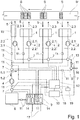
- first embodiment of a device according to the invention are as essential elements processing heads 1, drying devices 2, an exhaust pipe 3, a recirculating air line 6, a catalytic Oxidation unit 8, a sensor unit 10, a control unit 12 and a drying gas line 13 are present.
- the description of the first embodiment of the device according to the invention is based on the assumption that the device is in a normal operating state (continuous operation, no start-up or shut-down phase).
- processing heads 1 are each formed as a printing unit of a printing press. Each processing head 1 applies color of a hue to a material web M guided past the processing heads 1 in the direction of the arrow over predetermined processing periods.
- the substance mixture S applied by each of the processing heads 1 is symbolized as a sequence of differently shaped surfaces.
- the respective color is a substance mixture S which, in addition to color pigments, also contains at least one readily volatile organic solvent.
- the substance mixture S applied to the material web M is at least dried in the region of the respective processing head 1 by means of a drying device 2, wherein in each case a drying device 2 is assigned to a processing head 1.
- the drying device 2 has a drying gas supply line 2.1 for supplying air as a drying gas in the form of a drying gas stream 2.3 to the processing head 1 and for inflating the drying gas stream 2.3 on the material web M. If freshly applied substance mixture S is present on material web M, at least part of the solvent contained in substance mixture S is taken up and removed by the drying gas stream 2.3.
- an exhaust gas outlet 2.2 is provided on the drying device 2, through which the inflated drying gas flow 2.3 can be discharged again as an exhaust gas flow 5 out of the region of the processing head 1.
- the drying gas flow 2.3 in a region of the machining head 1 is inflated onto the material web M in order to dry an applied substance mixture S spatially close to the machining head 1.
- the exhaust gas flow 5 of a dryer 2 is greater than the drying gas stream 2.3 of the same dryer device 2.
- the exhaust gas discharges 2.2 open into an exhaust pipe 3.
- the individual exhaust gas streams 5 of the individual Dryers 2 as a common exhaust stream 5 combined and forwarded.
- a bridge dryer 15 is arranged, which completely spans the material web M.
- the bridge dryer 15 is otherwise constructed and connected as the dryer 2.
- Each drying gas supply 2.1 is in each case assigned a fan 4 for generating the drying gas stream 2.3 and controlled by the control unit 12.
- a fan 4 can be assigned to all or several drying gas supply lines 2.1.
- only one fan 4 may be present, through which the drying gas streams 2.3 are effected in all the drying devices 2. It is possible in further embodiments that fans 4 are exclusively or additionally associated with the exhaust gas outlets 2.2 and / or the exhaust pipe 3.
- a control element 7 is provided, through which the exhaust stream 5 into a first exhaust gas flow share 5.1 and a second exhaust gas flow share 5.2 is divided (each symbolized by arrows).
- the first exhaust gas stream portion 5.1 is passed into a recirculation line 6, which is connected to the drying gas line 13.
- the first exhaust gas stream portion 5.1 of the drying gas line 13 can be fed so that the first exhaust gas stream portion 5.1 the drying equipment 2 again as a drying gas stream 2.3 or as part of which can be fed.
- a fresh air supply 16 is arranged, which is connected via a control element 7 with the circulating air line 6 in connection.
- the first exhaust stream component 5.1 contains a certain proportion during ongoing printing operation of the device, i. a certain concentration, at least one solvent. This fraction is detectable by the sensor unit 10 and by sensors 11 which are signal-technically connected to the sensor unit (not all connections shown for reasons of clarity) and can be provided as the value of the concentration of the solvent. Sensors 11 are arranged in the first embodiment shown in the exhaust pipe 3, in the circulating air line 6 and in the drying gas line 13. Each exhaust outlet 2.2 and the exhaust pipe 3 is associated with a sensor 11, by each of which the concentration of the solvent in the exhaust stream 5 is detected (explosion protection sensors).
- a different number and / or a different arrangement of sensors 11 may be present.
- the second exhaust gas flow component 5.2 passes from the dividing acting control element 7 at the end of the exhaust pipe 3 to a fan 4, which is the fluid catalytic upstream of the catalytic oxidation unit 8. Between the upstream fan 4 and the catalytic oxidation unit 8, a designed as a heat sensor sensor 11 for determining the temperature of the second exhaust gas stream part 5.2 is present.
- the catalytic oxidation unit 8 is provided with a mixed oxide as a material of a catalyst having a space velocity of 8000 h -1 .
- the catalytic oxidation unit 8 takes place in the presence of the catalyst, a thermal reaction of the solvents contained in the second exhaust gas stream 5.2.
- the thermal reaction is exothermic, i. with release of heat energy. If the concentration of the solvent in the second exhaust gas stream portion 5.2 is high enough, the catalytic oxidation unit 8 is operated autothermally.
- the catalytic oxidation unit 8 is followed by a heat exchanger 9, through which the thermally reacted second exhaust gas stream portion 5.2 is passed as clean air.
- the heat exchanger 9 communicates with the circulating air line 6, so that by the action of the heat exchanger 9, the first exhaust gas flow component 5.1 can be heated in a controlled manner.
- sensors 11 for detecting the temperature of the first exhaust gas flow component 5.1 or the thermally converted second exhaust gas flow component 5.2 are present in the circulating air line 6 and after the catalytic oxidation unit.
- a control element 7 assigned to the heat exchanger 9 can be actuated by the control unit 12, by the action of which a quantity of heat transferred to the first exhaust gas flow component 5.1 is controllably adjustable.
- the second exhaust gas flow component 5.2 is discharged to the environment after flowing through the heat exchanger 9 via an exhaust gas discharge 17.
- filter 17 (not shown) may be associated with the further purification of the second exhaust gas stream part 5.2 in further embodiments of the device of the exhaust gas outlet.
- the heat exchanger 9 is connected to a supply line of the second exhaust gas stream part 5.2 to the catalytic oxidation unit 8, so that the temperature of the second exhaust gas stream part 5.2 can be controlled increased before the second exhaust gas stream portion 5.2 of the catalytic oxidation unit 8 is supplied.
- the required heat energy for heating the first exhaust gas flow component 5.1 and / or the second exhaust gas flow component 5.2 is obtained from the second exhaust gas flow component 5.2 leaving the catalytic oxidation unit 8 obtained and transmitted by the heat exchanger 9.
- the heat exchanger 9 has a heating element 14, which is controlled by the control unit 12.
- the heating element 14 consists of two independently controllable heating units (shown in simplified form), so that both the first exhaust gas flow component 5.1 and the second exhaust gas flow component 5.2 are independently heatable.
- the second exhaust gas stream component 5.2 is derived.
- the heated first exhaust gas stream component 5.1 is guided through the circulating air line 6 into the drying gas line 13. From there, the first exhaust gas flow component 5.1 returns to the drying devices 2.
- Fresh air supply 16 can be used to mix fresh air supply with the first exhaust gas flow component 5.1 if necessary.
- control unit 12 By the control unit 12, the drying devices 2, the controller elements 7, the heating elements 14 and the fan 4 can be controlled.
- the control unit 12 is signal-technically connected to the aforementioned elements (some of these compounds are shown by dashed lines).
- the sensor unit 10 receives the signals transmitted by the sensors 11 and uses these to detect the respective values of the temperatures and concentrations.
- the values are provided to the control unit 12.
- the values may be graphed in a further embodiment of the device.
- the temperature and / or concentration values may be displayed on a display of a plant controller.
- the values detected by the sensors 11 are also provided to a control unit 18.
- the control unit 18 is designed as a subunit of the control unit 12 and serves to regulate an O 2 content of the second exhaust gas flow component 5.2.
- at least one sensor 11 for detecting the O 2 content is designed and arranged between the upstream fan 4 and the catalytic oxidation unit 8, so that the O 2 content of the second exhaust gas flow component 5.2 can be measured by this sensor 11.
- the control unit 18 is data-technologically connected to a database 19 in which models are stored, by means of which a control of the O 2 content of the second exhaust gas stream part 5.2 by the control unit 18 takes place.
- a second embodiment of a device according to the invention is shown.
- the elements and their functioning with the in Fig. 1 shown device match.
- a fan 4 is present in the drying gas line 13 through which the drying gas streams 2.3 of all the drying devices 2 are effected.
- a heating element 14 for the controlled heating of the second exhaust gas stream part 5.2 is present between the dividing control element 7 at the end of the exhaust pipe 3 and the upstream of the catalytic oxidation unit 8 fan 4, a heating element 14 for the controlled heating of the second exhaust gas stream part 5.2 is present.
- the heating element 14 is actuated by the control device 12 if the temperature of the second exhaust gas flow component 5.2 is too low for efficient operation of the catalytic oxidation unit 8.
- a heating of the second exhaust gas stream portion 5.2 by means of the heat exchanger 9 is then optional.
- the heating of the second exhaust gas flow component 5.2 by means of the heating element 14 is optional.
- the heat exchanger 9 is only intended to heat if necessary only the second exhaust gas stream part 5.2.
- a heating element 14 upstream of the catalytic oxidation unit 8 is not present, but may be present in further embodiments of the device.
- the recirculation line 6 with the first exhaust gas stream portion 5.1 leads to the dry gas line 13.
- a further heat exchanger 9.1 is arranged, which is equipped with a heating element 14. This heating element 14 is connected to the control unit 12 in connection and can be controlled by this.
- the second exhaust gas stream portion 5.2 is passed as clean air after it has flowed through the heat exchanger 9. Whose heat energy can be transferred wholly or proportionately to the first exhaust gas stream share 5.1.
- a bypass of the further heat exchanger 9.1 is provided, so that the first exhaust gas stream portion 5.1 is then not passed through the other heat exchanger 9.1, when the temperature of the first exhaust gas stream portion 5.1 is above a threshold of 80 ° C here.
- other temperature values may be selected as the threshold value.
- a bypass (not shown) may also be provided on the heat exchanger 9.
- the material web M is guided past the processing heads 1.
- the respective processing heads 1 are activated at predetermined processing periods and a substance mixture S is applied to the material web M by them.
- Each processing head 1 is assigned a substance mixture S in the form of a printing ink.
- the control unit 12 controls the drying device 2 associated with the processing head 1 and puts it into operation. Since the machining heads 1 are basically of the same design, the following description refers, by way of example only, to a machining head 1.
- the fan 4 causes a drying gas flow 2.3 in the drying gas supply line 2.1 and blows it onto the material web M.
- the drying gas stream 2.3 passes over the substance mixture S applied to the material web M by the processing head 1, as a result of which proportionate volatile solvents escaping from the applied substance mixture S are taken up into the drying gas stream 2.3.
- a negative pressure is generated by way of the exhaust gas discharge line 2.2 in that the drying gas stream 2.3 containing the solvent is sucked off as the exhaust gas stream 5.
- the exhaust gas stream 5 passes through the exhaust gas outlet 2.2 in the exhaust pipe 3.
- the concentration of the solvent in the exhaust stream 5 is detected by a sensor 11 as a sensor signal and transmitted to the sensor unit 10. From the sensor signal, a value of the concentration of the solvent is detected and provided to the control unit 12.
- the dividing regulator element 7 is actuated at the end of the exhaust gas line 3 so that the largest part of the exhaust gas stream 5 is conducted into the recirculation air line 6 as first exhaust gas flow component 5.1 , Only the difference between the exhaust gas stream 5 and the drying gas stream 2.3 is fed to the catalytic oxidation unit 8 as the second exhaust gas stream component 5.2.
- the first exhaust gas stream portion 5.1 is fed to the heat exchanger 9 where it is heated and then passed into the drying gas line 13. From there, the first exhaust gas flow component 5.1 is supplied again as a drying gas stream 2.3 corresponding to a further processing period of the processing head 1.
- the drying gas flow 2.3 already contains solvent, but has not yet reached its absorption capacity. As described above, in turn applied substance mixture S is dried, wherein the concentration of the solvent in the exhaust gas stream 5 further increases.
- the dividing regulator element 7 is activated such that the second exhaust gas flow component 5.2 is proportionately increased and the first exhaust gas flow component 5.1 is correspondingly reduced proportionally.
- a drying device 2 is actuated by the control unit 12 whose associated processing head 1 does not undergo any processing period at this time. Additional ambient air, which contains no or only minimal amount of solvent, is sucked into the exhaust gas line 3 via this additionally controlled drying device 2 and the concentration of the solvent in the exhaust gas flow 5 is reduced.
- Such a reduction of the concentration can be triggered as a precaution, if the detected concentration of the solvent is already so high that further drying, for example by supplying a further exhaust stream 5 from a further dryer device 2, to exceed the desired working concentration or a maximum allowable concentration would lead.
- Such a future supply of a further exhaust gas stream 5 may be known since the control unit 12, the predetermined processing periods of the individual processing heads 1 are available and thus a predictive control of the concentration ratios in the device is possible.
- the admixing of ambient air to the exhaust gas stream 5 takes place in such quantities that the second exhaust gas stream component 5.2 has the desired working concentration.
- the temperature of the second exhaust gas flow component 5.2 is detected by means of a sensor 11 and compared with a desired temperature.
- the desired temperature is in a range over which the catalyst of the catalytic oxidation unit 8 operates particularly effectively. If the temperature of the second exhaust gas flow component 5.2 is too low, the control element 7, by which the second exhaust gas flow component 5.2 can be fed to the heat exchanger 9, is controlled by the control unit 12 and the second exhaust gas flow component 5.2 is fed to the heat exchanger 9. In this, the desired temperature of the second exhaust gas flow component 5.2 is set. If the desired temperature of the second exhaust gas flow component 5.2 can not be adjusted by means of the heat exchanger 9 alone, the heating element 14 of the heat exchanger 9 is additionally activated and the second exhaust gas flow component 5.2 is heated accordingly.
- the second exhaust gas flow component 5.2 is thermally converted and the heat energy thereby obtained is used to heat the first and second exhaust gas flow components 5.1 and 5.2 by means of the heat exchanger 9.
- a general model for controlling the O 2 content in the database 19 is stored before the device is put into operation, which is controlled by the control unit 18 is repeatedly retrievable.
- the device is subjected to different operating conditions during a trial operation. In this case, various parameters, such as the solvent concentration, the speed of the fan 4, the achieved working concentration, the O 2 content, temperatures, flow velocities and flow rates, recorded and stored in the form of data sets in the database 19.
- the general model is individually adapted to the specific device and individual models are stored in the database 19. Based on the datasets and individual models, simulations are also performed for scenarios that were not actually tested during trial operation. These simulations are extrapolations of the local / temporal evolution of acquired data series and / or the derivative (here also subsumed under the concept of extrapolation) of fictitious data series and fictitious data sets.
- Both the general model and the individual models are designed in such a way that unwanted overshoots and undershoots of limit values of predetermined parameters are canceled out by control commands of the control unit 18.
- the simulations are used to adapt the individual models such that predicted overshoots and undershoots of limit values do not occur at all.
- collected data series and data records are searched for distinctive data series or striking data records. If such distinctive data series or distinctive data records are found, an individual model is selected which is assigned to these distinctive data series or distinctive data records. If several individual models are associated with the identified distinctive data series or striking data records, the individual model is selected on the basis of the criterion of the greatest correspondence (similarity) of the data with the individual models available for selection.
- the response of the device is again detected and used as a record for adapting the general model or for adapting the individual model used for the control.
- the control of parameters such as the O 2 content is not based on the general model and only when an actual overrun or undercut a threshold, but it will be timely and taking into account the individual reaction (eg inertia) of concrete Device on the basis of a selected individual model control commands given by the control unit 18 to the corresponding controller elements 7.
Landscapes
- Health & Medical Sciences (AREA)
- General Health & Medical Sciences (AREA)
- Toxicology (AREA)
- Engineering & Computer Science (AREA)
- Mechanical Engineering (AREA)
- Drying Of Solid Materials (AREA)
- Exhaust Gas Treatment By Means Of Catalyst (AREA)
- Treatment Of Fiber Materials (AREA)
Description
Die Erfindung betrifft eine Vorrichtung zum Aufbringen von jeweils mindestens ein organisches Lösungsmittel enthaltenden Stoffgemischen auf eine Materialbahn. Die Erfindung betrifft ferner ein Verfahren zur Bereitstellung eines Anteils eines Abgasstromes für eine in der Vorrichtung integrierte katalytische Oxidationseinheit. Vorrichtung und Verfahren sind gattungsgemäß aus der
Werden lösungsmittelhaltige Stoffgemische, wie beispielsweise Farben, Lacke oder Kunststoffmischungen, auf Oberflächen von Materialien aufgebracht, kommt es anschließend zumeist zu einem Verdunsten der Lösungsmittel, die z. B. zur Lösung von Farb- oder Lackkomponenten oder als Weichmacher fungieren. Die Verdunstungsrate des Lösungsmittels hängt dabei von verschiedenen Bedingungen, wie der Art der oder des Lösungsmittel(-s), der Lösungsmitteltemperatur, den Umgebungstemperaturen, der Belüftungsintensität oder der Umgebungsdrücke, ab.Become solvent-containing mixtures, such as paints, coatings or plastic mixtures, applied to surfaces of materials, it is then usually to evaporation of the solvent, the z. B. to solve paint or paint components or act as a plasticizer. The evaporation rate of the solvent depends on various conditions, such as the type of solvent or solvent (s), the solvent temperature, the ambient temperatures, the ventilation intensity or the ambient pressures from.
Beim Bedrucken oder Beschichten (fortan zusammengefasst als: Aufbringen) von Materialien, insbesondere von Materialbahnen, z. B. von Rollen von Verpackungsmaterialien, Papier, Folien, Blechen, Kunststoffen, Verbundwerkstoffen wie mehrschichtigen Folien, Spanplatten, Leimholzplatten oder Bahnen von Glas oder Naturstoffen wie Holz, dient das mindestens eine Lösungsmittel unter anderem dazu, das Stoffgemisch hinreichend flüssig zu halten, um eine störungsfreie Verarbeitung zu ermöglichen und eine gute Haftung des Stoffgemisches auf der Oberfläche des Materials zu erzielen.When printing or coating (henceforth summarized as: application) of materials, especially webs, z. B. of rolls of packaging materials, paper, films, sheets, plastics, composite materials such as multilayer films, chipboard, glued wood panels or sheets of glass or natural materials such as wood, the at least one solvent serves, inter alia, to keep the mixture sufficiently liquid to a To allow trouble-free processing and to achieve good adhesion of the mixture on the surface of the material.
Werden lösungsmittelhaltige Stoffgemische auf Materialbahnen aufgebracht, beispielsweise aufgedruckt, muss eine Konzentration der Lösungsmittel in den aufgebrachten Stoffgemischen schnell soweit abgesenkt werden, dass ein Überdrucken bzw. ein Aufwickeln der Materialbahn ermöglicht ist, ohne dass es zu einem Verwischen des aufgebrachten Stoffgemisches kommt. Die Senkung der Lösungsmittelkonzentration erfolgt üblicherweise mittels Trocknung des aufgebrachten Stoffgemisches durch die Zufuhr von Luftströmen oder durch Bestrahlung, beispielsweise mit Infrarotstrahlung. Um eine schnelle Trocknung zu erlauben, werden in den Stoffgemischen leicht flüchtige Lösungsmittel (VOC = volatile organic compounds; inklusive VVOC = very volatile organic compounds; DIN EN ISO 16000-6; California specification section 01350; RiLi 1993/13/EG; insbesondere aber RiLi 2004/42/EG) verwendet. Die Trocknung kann neben einer Verringerung der in dem aufgebrachten Stoffgemisch enthaltenen Lösungsmittelkonzentration auch eine Zersetzung bzw. Umsetzung von Stoffen des Stoffgemischs beinhalten. Die Trocknungsparameter werden der gewünschten Druckgeschwindigkeit angepasst.Solvent-containing mixtures are applied to webs of material, for example, printed, a concentration of the solvent in the applied mixtures must be quickly lowered so far that overprinting or winding of the web is possible without causing blurring of the applied mixture. The reduction of the solvent concentration is usually carried out by drying the applied substance mixture by the supply of air streams or by irradiation, for example with infrared radiation. In order to allow rapid drying, highly volatile organic compounds (VOC = very volatile organic compounds; DIN EN ISO 16000-6; California specification section 01350; RiLi 1993/13 / EC; but especially RiLi 2004/42 / EC). The drying may include, in addition to a reduction in the solvent concentration contained in the applied mixture, a decomposition or conversion of substances of the mixture. The drying parameters are adjusted to the desired printing speed.
Die zur Trocknung genutzte Luft ist nach der Trocknung mit Lösungsmittel und / oder mit Zersetzungsprodukten beladen und wird als Abgasstrom von der Materialbahn abgeführt. Daraus ergeben sich zwei Erfordernisse. Zum Ersten muss verhindert werden, dass an irgendeinem Bereich der Vorrichtung die Lösungsmittelkonzentration in dem Abgasstrom Werte erreicht, bei denen eine unzulässig große Explosionsgefahr des Abgasstromes besteht. Technisch wird durch die Angabe einer unteren Explosionsgrenze (UEG) und einer oberen Explosionsgrenze (OEG) in Gramm Lösungsmittel je Kubikmeter ein unzulässiger Wertebereich der Lösungsmittelkonzentration angegeben. Zum Zweiten müssen die Lösungsmittel geeignet behandelt werden, damit der Abgasstrom unter Einhaltung von Umweltschutz- und Arbeitsschutzauflagen an die Umgebung abgegeben werden kann. Eine Reinigung erfolgt zumeist durch eine thermische Umsetzung der in dem Abgasstrom oder in einem Anteil des Abgasstromes enthaltenen Lösungsmittel. Eine thermische Umsetzung, üblicherweise eine (Nach-)Verbrennung, ist ein oxidativer Prozess, der vorzugsweise unter Anwesenheit eines geeigneten Katalysators durchgeführt wird. Wichtig hierbei ist das Verhältnis zwischen Sauerstoff und Schadstoff. Die oxidierbare Menge an Schadstoffen ist durch die zur Verfügung stehende Menge an Sauerstoff bestimmt. Bei Edelmetallkatalysatoren muss mindestens ein Überschuss an Sauerstoff von 2 % vorliegen. Werden metalloxidische Verbindungen eingesetzt, beträgt der Überschuss mindestens 12 %. Bei einer direkten Rückführung des Abgases aus einer katalytischen Oxidationseinheit bedeutet dies bei 12 g/m3 Ethanol als Schadstoff, dass bei gleichem Gesamtvolumenstrom maximal 80 % des Abgases rückgeführt und wiederverwendet werden können.The air used for drying is loaded after drying with solvent and / or decomposition products and is discharged as exhaust gas flow from the web. This results in two requirements. First, it must be prevented that at any area of the device, the solvent concentration in the exhaust gas flow reaches values at which there is an inadmissibly high risk of explosion of the exhaust gas flow. Technically, the indication of a lower explosion limit (LEL) and an upper explosion limit (LEL) in grams of solvent per cubic meter indicates an impermissible value range of the solvent concentration. Secondly, the solvents must be suitably treated so that the exhaust gas flow can be released to the environment in compliance with environmental and occupational safety regulations. Cleaning is usually carried out by a thermal reaction of the solvents contained in the exhaust gas stream or in a portion of the exhaust gas stream. A thermal reaction, usually a (post) combustion, is an oxidative process, which is preferably carried out in the presence of a suitable catalyst. Important here is the relationship between oxygen and pollutant. The oxidizable amount of pollutants is determined by the amount of oxygen available. For noble metal catalysts, there must be at least an excess of oxygen of 2%. If metal oxide compounds are used, the excess is at least 12%. With a direct recirculation of the exhaust gas from a catalytic oxidation unit, this means at 12 g / m 3 of ethanol as a pollutant, that at the same total volume flow maximum 80% of the exhaust gas can be recycled and reused.
Aus dem Stand der Technik, beispielsweise aus der
In der
Aus der
Sind in einer Vorrichtung mehrere Druckwerke vorhanden, mit denen das mindestens eine Stoffgemisch auf die Materialbahn aufgebracht wird, können diese Druckwerke jeweils Trocknungsgaszuleitungen und Abgasableitungen aufweisen, wie dies in der
Die Möglichkeit einer Erhöhung der Lösungsmittelkonzentration des Abgasstromes durch mehrfaches Zuführen des ersten Abgasstromanteils zur Trocknung ist beispielsweise auch aus der
Nachteilig an den aus dem Stand der Technik bekannten Lösungen ist, dass der zweite Abgasstromanteil im Bereich von Sekunden oder weniger Minuten entweder periodisch oder zufällig schwankende Lösungsmittelkonzentrationen aufweist. Damit schwanken auch die Bedingungen, unter denen ein in der katalytischen Oxidationseinheit vorhandener Katalysator betrieben ist. Für den effizienten Einsatz eines Katalysators sind jedoch konstante Betriebsbedingungen von Vorteil.A disadvantage of the solutions known from the prior art is that the second proportion of exhaust gas in the range of seconds or less minutes has either periodically or randomly varying solvent concentrations. This also varies the conditions under which one in the catalytic Oxidation unit existing catalyst is operated. For the efficient use of a catalyst, however, constant operating conditions are advantageous.
Der Erfindung liegt die Aufgabe zugrunde eine Möglichkeit vorzuschlagen, mittels der ein Abgasstrom, der mindestens ein Lösungsmittel enthält, über lange Zeiträume und unter Anwesenheit eines Katalysators effizient gereinigt werden kann. Die Aufgabe ist für eine Vorrichtung zum Aufbringen von Stoffgemischen auf eine Materialbahn zu lösen.The invention has for its object to propose a way by which an exhaust gas stream containing at least one solvent can be efficiently cleaned for long periods and in the presence of a catalyst. The object is to be solved for a device for applying mixtures of substances on a material web.
Die Aufgabe wird durch die Gegenstände der unabhängigen Ansprüche gelöst. Vorteilhafte Ausgestaltungen finden sich in den abhängigen Ansprüchen.The object is solved by the subject matters of the independent claims. Advantageous embodiments can be found in the dependent claims.
Die Aufgabe wird durch eine Vorrichtung zum Aufbringen von jeweils mindestens ein organisches Lösungsmittel enthaltenden Stoffgemischen auf eine Materialbahn gemäß Anspruch 1 gelöst.The object is achieved by a device for applying mixtures of substances containing at least one organic solvent to a material web according to
Die katalytische Oxidationseinheit ist eine mit einem Katalysator versehene thermische Oxidationseinheit.The catalytic oxidation unit is a catalyzed thermal oxidation unit.
Kern der Erfindung ist die gezielte Einstellung einer konstanten Konzentration des Lösungsmittels als Arbeitskonzentration (auch als konstante Arbeitskonzentration bezeichnet) des zweiten Abgasstromanteils, wodurch dieser Betriebsparameter der katalytischen Oxidationseinheit stabil gehalten ist.The core of the invention is the targeted adjustment of a constant concentration of the solvent as working concentration (also referred to as constant working concentration) of the second exhaust gas flow component, whereby this operating parameter of the catalytic oxidation unit is kept stable.
Unter einer konstanten Arbeitskonzentration ist eine konstante Konzentration des mindestens einen Lösungsmittels in dem zweiten Abgasstromanteil zu verstehen, die um nicht mehr als 10% eines Soll-Wertes schwankt. Dabei versteht sich, dass während der Phasen des Anlaufens und des Abschaltens der erfindungsgemäßen Vorrichtung größere Schwankungen auftreten können. Liegen mehrere Lösungsmittel in ihren jeweiligen Konzentrationen in dem zweiten Abgasstromanteil vor, wird unter der Arbeitskonzentration eine resultierende Konzentration aller vorliegenden Lösungsmittel verstanden.A constant working concentration is to be understood as meaning a constant concentration of the at least one solvent in the second offgas stream component which does not fluctuate by more than 10% of a desired value. It is understood that during the phases of startup and shutdown of the device according to the invention greater fluctuations may occur. If there are several solvents in their respective concentrations in the second exhaust gas stream fraction, the working concentration is understood as meaning a resulting concentration of all the solvents present.
Die Arbeitskonzentration ist ein gewünschter Bereich von Konzentrationswerten des mindestens einen Lösungsmittels in dem zweiten Abgasstromanteil, bei der die thermische Oxidationseinheit betrieben wird. Vorzugsweise arbeitet die thermische Oxidationseinheit bei Vorliegen der Arbeitskonzentration ganz oder über Teilbereiche der Arbeitskonzentration autotherm. Die Arbeitskonzentration kann frei ausgewählt werden. Die ausgewählte Arbeitskonzentration wird, im Rahmen technisch bedingter und dem Fachmann bekannter Schwankungen, konstant gehalten. Im Laufe der Verfahrensdurchführung kann eine neue Arbeitskonzentration ausgewählt werden. Für diese gilt das vorstehend Erläuterte entsprechend.The working concentration is a desired range of concentration values of the at least one solvent in the second exhaust gas stream portion at which the thermal oxidation unit is operated. In the presence of the working concentration, the thermal oxidation unit preferably works completely autothermally or over partial ranges of the working concentration. The working concentration can be freely selected. The selected working concentration is kept constant within the framework of technical fluctuations known to the person skilled in the art. In the course of the procedure, a new working concentration can be selected. For these, the above explained applies accordingly.
Unter einer katalytischen Oxidationseinheit wird eine Vorrichtung verstanden, in der unter Anwesenheit und unter Mitwirkung mindestens eines Katalysators der zweite Abgasstromanteil thermisch umgesetzt wird. Vorzugsweise ist die Arbeitskonzentration so gewählt, dass eine weitest gehende oder vollständige thermische Umsetzung des mindestens einen Lösungsmittels durch die katalytische Oxidationseinheit erfolgen kann. Besonders vorteilhaft ist, wenn die technische Ausführung der katalytischen Oxidationseinheit und die Betriebsparameter zu deren Betrieb, beispielsweise die Arbeitskonzentration, das Material und die Dimensionierung des Katalysators sowie eine Eingangstemperatur des zweiten Abgasstromanteils, so aufeinander abgestimmt sind, dass eine thermische Umsetzung exotherm verläuft. Vorzugsweise wird bei der thermischen Umsetzung soviel Energie, insbesondere Wärmeenergie, freigesetzt, dass die thermische Umsetzung exotherm verläuft und die katalytische Oxidationseinheit autotherm betrieben werden kann. Die katalytische Oxidationseinheit ist nach einer Anlaufphase der Vorrichtung vorteilhafterweise eine autotherme Einheit.A catalytic oxidation unit is understood to mean a device in which, in the presence and with the cooperation of at least one catalyst, the second exhaust gas flow component is thermally converted. Preferably, the working concentration is selected so that a far-reaching or complete thermal reaction of the at least one solvent can be carried out by the catalytic oxidation unit. It is particularly advantageous if the technical design of the catalytic oxidation unit and the operating parameters for their operation, for example, the working concentration, the material and the dimensioning of the catalyst and an inlet temperature of the second exhaust gas flow component, are coordinated so that a thermal conversion is exothermic. During the thermal conversion, it is preferable to release so much energy, in particular heat energy, that the thermal conversion takes place exothermically and the catalytic oxidation unit can be operated autothermally. The catalytic oxidation unit is advantageously an autothermal unit after a start-up phase of the device.
Als Material des Katalysators ist vorzugsweise ein Mischmetalloxid, Metalloxid oder Metall, insbesondere ein oder mehrere Edelmetalle gewählt. In einer vorteilhaften Ausführung der erfindungsgemäßen Vorrichtung ist das Katalysatormaterial ein Material auf Mischmetalloxidbasis, insbesondere ein Material der Klassen der Spinelle und Perowskite. Günstig ist, wenn als Material des Katalysators ein Material oder mehrere Materialien gewählt sind, durch deren Katalysatorvolumen Raumgeschwindigkeiten in einem Bereich von vorzugsweise 5000 bis 20000 h-1 erreicht werden. Vorteilhaft ist beispielsweise ein Katalysatorvolumen mit einer Raumgeschwindigkeit von etwa 8000 h-1 oder höher. Je höher die Raumgeschwindigkeit gewählt wird, desto kleiner kann die katalytische Oxidationseinheit ausgelegt werden. Bei geringen Raumgeschwindigkeiten ist die Verweildauer des zweiten Abgasstromanteils in Kontakt mit dem Katalysator länger als bei höheren Raumgeschwindigkeiten. Dadurch ist es gegenüber dem Stand der Technik möglich, die Temperatur, bei der die thermische Umsetzung durchgeführt wird, um etwa 20 bis 50 K zu senken. Katalysatoren aus Edelmetall zeigen diesen Effekt bei Temperaturen < 280 °C nicht. Die Raumgeschwindigkeit ist eine Größe, die während des Betriebs der erfindungsgemäßen Vorrichtung variieren kann und beispielweise von dem Verhältnis des Volumenstromes des zweiten Abgasstromanteils und des Volumens der katalytischen Oxidationseinheit sowie des Katalysatorvolumens abhängt.The material of the catalyst is preferably a mixed metal oxide, metal oxide or metal, in particular one or more noble metals. In an advantageous embodiment of the device according to the invention, the catalyst material is a material based on mixed metal oxide, in particular a material of the classes of spinels and perovskites. It is favorable if, as material of the catalyst, one or more materials are selected, through the catalyst volume of which space velocities in a range of preferably 5000 to 20,000 h -1 are achieved. For example, a catalyst volume with a space velocity of about 8000 h -1 or higher is advantageous. The higher the space velocity is chosen, the smaller the catalytic oxidation unit can be designed. At low space velocities, the residence time of the second proportion of exhaust gas in contact with the catalyst is longer than at higher space velocities. Thus, it is possible over the prior art to lower the temperature at which the thermal conversion is carried out by about 20 to 50 K. Noble metal catalysts do not show this effect at temperatures <280 ° C. The space velocity is a size which may vary during operation of the device according to the invention and, for example, depends on the ratio of the volume flow of the second exhaust gas stream proportion and the volume of the catalytic oxidation unit and the catalyst volume.
Das Stoffgemisch kann beispielsweise eine Farbe eines bestimmten Farbtons sein. Neben anderen Stoffen wie Trägern, Dispergatoren und organischen chemischen Verbindungen ist mindestens ein organisches Lösungsmittel Bestandteil des Stoffgemisches. Das Lösungsmittel ist vorzugsweise bereits bei Raumtemperaturen leicht flüchtig (hoher Partialdruck), d.h. es kann vorzugsweise bei Raumtemperatur durch Aufblasen eines geeigneten Trocknungsgases zu einem erheblichen Anteil aus dem Stoffgemisch entfernt werden. Durch Verwendung eines erwärmten Trocknungsgases ist das mindestens eine Lösungsmittel noch leichter zu entfernen, da die Flüchtigkeit des Lösungsmittels bei Wärmezufuhr zunimmt. Auch ist die Kapazität zur Aufnahme von Lösungsmitteln bei einem erwärmten Trocknungsgas erhöht.The mixture of substances may, for example, be a color of a specific hue. In addition to other substances such as carriers, dispersants and organic chemical compounds, at least one organic solvent is a constituent of the substance mixture. The solvent is preferably already volatile at room temperature (high partial pressure), i. it may preferably be removed at room temperature by blowing a suitable drying gas to a considerable extent from the mixture. By using a heated drying gas, the at least one solvent is even easier to remove because the volatility of the solvent increases with heat input. Also, the capacity for containing solvents is increased with a heated drying gas.
Als Trocknungsgas ist vorzugsweise Luft verwendet. Die Luft kann bereits einen Anteil mindestens eines Lösungsmittels enthalten, soll aber bezüglich jedes der enthaltenen Lösungsmittel nicht gesättigt sein. Die Luft wird zum einen an den Bearbeitungsköpfen angesaugt. Vorteilhaft ist eine zusätzliche Frischluftzuführung beispielsweise an einer Umluftleitung vorhanden. Die Frischluftzuführung ist vorzugsweise über ein Reglerelement mit der Umluftleitung verbunden.As the drying gas, air is preferably used. The air may already contain a proportion of at least one solvent, but should not be saturated with respect to each of the solvents contained. The air is sucked in on the processing heads. Advantageously, an additional fresh air supply, for example, to a recirculation line available. The fresh air supply is preferably connected via a regulator element with the recirculation line.
Die Umluftleitung dient einer Rückführung des ersten Abgasstromanteils zur Trocknungsgasleitung.The recirculation line serves to return the first proportion of exhaust gas flow to the drying gas line.
Um dem Trocknungsgasstrom eine zur Trocknung günstige Temperatur zu verleihen und um die Temperatur des Trocknungsgasstromes einstellen zu können, ist den einzelnen Trocknungsgaszuleitungen und / oder diesen, in einem Bereich einer gemeinsamen Trocknungsgasleitung, vorgeschaltet ein gemeinsamer Wärmetauscher angeordnet. Der oder die Wärmetauscher kann / können eine Heizeinheit aufweisen, mittels der die Temperatur des Trocknungsgasstromes einstellbar ist, insbesondere erhöht werden kann. Es ist möglich, dass eine steuerbare Umgehung einzelner Wärmetauscher oder von Gruppen von Wärmetauschern vorgesehen ist, die durch entsprechende Ansteuerung der Reglerelemente ganz, teilweise oder nicht aktiviert sind, sodass der gesamte, ein Teil oder kein Trocknungsgasstrom durch den oder die Wärmetauscher geführt ist.In order to give the Trocknungsgasstrom a temperature favorable for drying and to adjust the temperature of the drying gas stream, the individual Trocknungsgaszuleitungen and / or this, in a region of a common drying gas line, upstream of a common heat exchanger is arranged. The one or more heat exchangers can / have a heating unit, by means of which the temperature of the drying gas flow is adjustable, in particular can be increased. It is possible that a controllable bypass of individual heat exchangers or groups of heat exchangers is provided, which are fully, partially or not activated by appropriate control of the control elements, so that the entire, a part or no drying gas is passed through the heat exchanger or the.
Das mindestens eine Lösungsmittel ist ein organisches Lösungsmittel, insbesondere Aceton, Methylpropanol, Ethylpropanol oder Ethanol. Weitere Lösungsmittel sind beispielsweise Methanol, Propanol, Iso-Propanol, Ethylacetat oder n-Hexan, wobei grundsätzlich jedes geeignete organische Lösungsmittel allein oder in Mischung verwendet werden kann. Geeignet ist ein Lösungsmittel beispielsweise, wenn es keine oder tolerable nachteilige Wirkungen auf das Stoffgemisch und / oder auf die Materialbahn hat. Es können auch beliebige Gemische organischer Lösungsmittel verwendet sein. Es wird statt von mindestens einem Lösungsmittel oder von einem Lösungsmittelgemisch nachfolgend auch vereinfachend von einem oder von dem Lösungsmittel besprochen.The at least one solvent is an organic solvent, in particular acetone, methylpropanol, ethylpropanol or ethanol. Further solvents are, for example, methanol, propanol, isopropanol, ethyl acetate or n-hexane, it being possible in principle to use any suitable organic solvent, alone or in admixture. For example, a solvent is suitable if it has no or tolerable adverse effects on the composition and / or on the web. Any mixtures of organic solvents may also be used. Instead of at least one solvent or of a solvent mixture, it is also discussed below in a simplified manner of one or the solvent.
Ein weiterer wichtiger Aspekt der Erfindung liegt darin, dass ein Abfall einer Sauerstoffkonzentration des zweiten Abgasstromanteils vermieden oder zumindest nur in einem sehr geringen Umfang zugelassen wird. Die Sauerstoffkonzentration ist durch die anwesenden Sauerstoffatome bestimmt und bedingt nicht nur das Vorhandensein von molekularem Sauerstoff O2. Trotzdem wird die Sauerstoffkonzentration fortan auch vereinfachend als O2-Gehalt bezeichnet.Another important aspect of the invention is that a drop in an oxygen concentration of the second proportion of exhaust gas flow is avoided or at least allowed only to a very small extent. The oxygen concentration is determined by the oxygen atoms present and not only the presence of molecular oxygen O 2 . Nevertheless, the oxygen concentration is henceforth also referred to simply as O 2 content.
Der O2-Gehalt ist insbesondere für die Vorgänge in der katalytischen Oxidationseinheit von großer Bedeutung. Aus dem Stand der Technik (z. B.
In einer günstigen Ausführung der erfindungsgemäßen Vorrichtung ist eine Regelungseinheit zur Regelung einer Eingangstemperatur des zweiten Abgasstromanteils bei dessen Eintritt in die katalytische Oxidationseinheit vorhanden. Diese Regelungseinheit ist vorteilhaft so konfiguriert, dass die Eingangstemperatur bei einem Betrieb der erfindungsgemäßen Vorrichtung auf höchstens 240°C eingestellt ist, wodurch zum Betrieb der erfindungsgemäßen Vorrichtung weniger Energie benötigt wird.In a favorable embodiment of the device according to the invention, a control unit is provided for controlling an inlet temperature of the second exhaust gas flow component as it enters the catalytic oxidation unit. This control unit is advantageously configured so that the input temperature is set to at most 240 ° C during operation of the device according to the invention, whereby less energy is required to operate the device according to the invention.
Um einer Senkung des O2-Gehalts zu begegnen, ist die katalytische Oxidationseinheit vorzugsweise flammenlos geheizt, d. h. innerhalb der katalytischen Oxidationseinheit wird keine Form einer Verbrennung unter Ausbildung einer Flamme durchgeführt. Die erfindungsgemäße Vorrichtung weist daher vorzugsweise Heizelemente auf, durch die ein flammenloses Heizen ermöglicht ist.In order to counteract a lowering of the O 2 content, the catalytic oxidation unit is preferably heated flamelessly, ie within the catalytic oxidation unit, no form of combustion is carried out to form a flame. The device according to the invention therefore preferably has heating elements, by means of which flameless heating is enabled.
Es ist beispielsweise möglich, dass die katalytische Oxidationseinheit indirekt mittels einer Flamme geheizt wird, indem mit der Flamme ein Bereich der Außenwand der katalytischen Oxidationseinheit direkt geheizt ist oder indem mittels einer Flamme ein Heizmedium erwärmt wird, dessen Wärmeenergie mittels eines Wärmetauschers auf die katalytische Oxidationseinheit, insbesondere auf das Katalysatormaterial, übertragen ist.For example, it is possible that the catalytic oxidation unit is heated indirectly by means of a flame by directly heating with the flame a portion of the outer wall of the catalytic oxidation unit or by heating by means of a flame a heating medium whose heat energy is transferred to the catalytic oxidation unit by means of a heat exchanger. in particular to the catalyst material, is transferred.
In alternativen oder einander ergänzenden Ausführungen der erfindungsgemäßen Vorrichtung kann die Heizung auch mittels Mikrowellenstrahlung, Infrarotstrahlung, Ultraschallwellen, induktiv oder durch den Betrieb ohmscher Widerstände realisiert sein. Zur Heizung der katalytischen Oxidationseinheit und / oder zum Betrieb der erfindungsgemäßen Vorrichtung und / oder derer Komponenten kann Energie, insbesondere elektrische Energie, aus regenerativen Quellen, wie der Sonnenstrahlung oder der Wind-, Wasser- oder Gezeitenkraft, genutzt sein.In alternative or complementary embodiments of the device according to the invention, the heating can also by means of microwave radiation, infrared radiation, Ultrasonic waves, be realized inductively or by the operation of ohmic resistors. For heating the catalytic oxidation unit and / or for operating the device according to the invention and / or components thereof, energy, in particular electrical energy, from regenerative sources, such as solar radiation or wind, water or tidal power, can be used.
Eine solche flammenlose Heizung hat den Vorteil, dass der O2-Gehalt nicht durch den Heizvorgang gesenkt wird und ein gegenüber dem Stand der Technik hoher O2-Gehalt für die katalytische Oxidation zur Verfügung steht. Aufgrund des hohen O2-Gehalts ist eine größere Menge Lösungsmittel thermisch umsetzbar als in katalytischen Oxidationseinheiten gemäß dem Stand der Technik. Auch sind die Umsatzraten bzw. die Abbauraten wesentlich höher als im Stand der Technik, da die Wahrscheinlichkeit, dass ein Sauerstoffmolekül/-atom auf ein Schadstoffmolekül trifft, wesentlich höher ist.Such a flameless heater has the advantage that the O 2 content is not lowered by the heating process and that a high O 2 content for the catalytic oxidation is available compared to the prior art. Due to the high O 2 content, a larger amount of solvent is thermally convertible than in catalytic oxidation units according to the prior art. Also, the conversion rates and the degradation rates are much higher than in the prior art, since the probability that an oxygen molecule / atom encounters a pollutant molecule is much higher.
Um die vorstehend umrissenen Vorteile nutzbar werden zu lassen, weist die erfindungsgemäße Vorrichtung wenigstens einen Regelkreis zur Erfassung aktueller O2-Gehalte und zur Regelung von O2-Gehalten der erfindungsgemäßen Vorrichtung auf. Ein Regelkreis besteht dabei wenigstens aus einem Mittel zur Erfassung aktueller O2-Gehalte, einem Mittel zur Regulierung eines örtlichen O2-Gehaltes sowie einer Regelungseinheit zur Ansteuerung des Mittels zur Regulierung eines örtlichen O2-Gehaltes aufgrund der von dem Mittel zur Erfassung aktueller O2-Gehalte bereitgestellten Messwerte.In order to make use of the advantages outlined above, the device according to the invention has at least one control circuit for detecting current O 2 contents and for controlling O 2 contents of the device according to the invention. A control circuit consists at least of a means for detecting current O 2 contents, a means for regulating a local O 2 content and a control unit for controlling the means for regulating a local O 2 content on the basis of the means for detecting current O. 2 levels provided readings.
Mittel zur Erfassung aktueller O2-Gehalte sind vorzugsweise Sauerstoffsensoren. Der O2-Gehalt wird günstigerweise am Eingang der katalytischen Oxidationseinheit erfasst. Er kann in weiteren Ausführungen auch an weiteren Orten, beispielsweise in der Abgasleitung, der Trocknungsgaszuleitung und / oder an den Trocknereinrichtungen erfasst sein.Means for detecting current O 2 contents are preferably oxygen sensors. The O 2 content is conveniently detected at the entrance of the catalytic oxidation unit. In further embodiments, it can also be detected at further locations, for example in the exhaust gas line, the drying gas supply line and / or at the drying devices.
Ein Mittel zur Regulierung eines örtlichen O2-Gehalts ist beispielsweise ein ansteuerbares Reglerelement wie eine Klappe oder ein Ventil, bei dessen Betätigung dem zweiten Abgasstromanteil ein sauerstoffhaltiges Gas zumischbar ist. Das Mittel zur Regulierung eines örtlichen O2-Gehalts kann vor einem Eingang der katalytischen Oxidationseinheit in der Abgasleitung angeordnet sein. Das Mittel kann in weiteren Ausführungen auch in anderen Leitungen der erfindungsgemäßen Vorrichtung, beispielsweise in einer Abgasableitung, der Umluftleitung, der Trocknungsgaszuleitung oder einer anderen geeigneten Leitung, angeordnet sein. Es ist ferner möglich, dass in einer erfindungsgemäßen Vorrichtung mehrere Mittel zur Regulierung angeordnet sind, die zudem an denselben oder an verschiedenen Leitungen vorhanden sind.A means for regulating a local O 2 content is, for example, a controllable control element such as a flap or a valve, upon actuation of which an oxygen-containing gas can be mixed with the second exhaust gas flow component. The middle for regulating a local O 2 content may be arranged in front of an inlet of the catalytic oxidation unit in the exhaust pipe. The means may be arranged in other embodiments in other lines of the device according to the invention, for example in an exhaust gas discharge line, the recirculating air line, the drying gas supply line or another suitable line. It is also possible that in a device according to the invention a plurality of means are arranged for regulation, which are also present on the same or on different lines.
Die Regelungseinheit kann dieselbe sein, die zur Einstellung der Eingangstemperatur dient. Sie kann außerdem als Bestandteil einer Steuerungseinheit der erfindungsgemäßen Vorrichtung ausgeführt sein.The control unit may be the same one used to adjust the input temperature. It can also be designed as part of a control unit of the device according to the invention.
Die Regelungseinheit ist in einer sehr vorteilhaften Ausführung so konfiguriert, dass eine Regelung des O2-Gehalts anhand einer mathematischen Modellrechnung erfolgen kann. Eine solche Modellrechnung (fortan auch kurz: Modell) dient insbesondere dazu, hohe Werte der Arbeitskonzentration sowie geringe Werte des O2-Gehalts zu vermeiden. Durch zu hohe Werte der Arbeitskonzentration kann die Temperatur in der katalytischen Oxidationseinheit zu stark ansteigen und das Katalysatormaterial schädigen. Zu geringe O2-Gehalte führen zu einer nur unvollständigen thermischen Umsetzung des wenigstens einen Lösungsmittels.The control unit is configured in a very advantageous embodiment so that a control of the O 2 content can be done using a mathematical model calculation. Such a model calculation (henceforth also short: model) serves in particular to avoid high values of the working concentration and low values of the O 2 content. Too high values of the working concentration may cause the temperature in the catalytic oxidation unit to increase too much and damage the catalyst material. Too low O 2 contents lead to an incomplete thermal reaction of the at least one solvent.
Als Ausgangsdaten für die Erstellung eines Modells kann die individuelle Konfiguration der erfindungsgemäßen Vorrichtung verwendet sein. Dabei können vorrichtungsseitige individuelle Konstruktionsmerkmale wie die Länge und Führung von Leitungen, individuelle Parameter wie Ströme des Abgases, des Trocknungsgases, der Frischluft, der Abluft sowie der Leistungsfähigkeit von Komponenten der Vorrichtung wie Lüftern und / oder Heizelementen in das Modell eingehen. Zusätzlich können umgebungsbedingte Parameter wie Umgebungs- und Betriebstemperaturen, Luftfeuchte und / oder ein Belüftungszustand der Umgebung der Vorrichtung in dem Modell Berücksichtigung finden.As the starting data for the creation of a model, the individual configuration of the device according to the invention can be used. In this case, device-side individual design features such as the length and routing of lines, individual parameters such as flows of the exhaust gas, the drying gas, the fresh air, the exhaust air and the performance of components of the device such as fans and / or heating elements can enter the model. In addition, environmental parameters such as ambient and operating temperatures, humidity and / or aeration state of the device environment may be considered in the model.
Mittels eines an eine konkrete Vorrichtung individuell angepassten und verifizierten Modells sind eine Einstellung und Regelung einer konstanten Arbeitskonzentration sowie die Einstellung und Regelung des O2-Gehalts ermöglicht. In vereinfachten Ausführungen der Vorrichtung kann das Modell auf Annahmen zu ausgewählten vorrichtungsseitigen Konstruktionsmerkmalen und / oder zu umgebungsbedingten Parametern beruhen.By means of a model which is individually adapted and verified to a specific device, it is possible to set and regulate a constant working concentration and to set and regulate the O 2 content. In simplified embodiments of the device, the model may be based on assumptions about selected device-side design features and / or environmental parameters.
Zur Regelung des O2-Gehalts kann in einer Ausführung der Vorrichtung wenigstens eines der Reglerelemente durch die Regelungseinheit ansteuerbar sein. Durch eine gesteuerte Zuführung von Frischluft sind die Arbeitskonzentration und der O2-Gehalt regelbar.To control the O 2 content, in one embodiment of the device at least one of the controller elements can be controlled by the control unit. By a controlled supply of fresh air, the working concentration and the O 2 content can be regulated.
In einer besonders vorteilhaften Ausführung sind Messkurven der O2-Gehalte sowie Messwerte, beispielsweise der Arbeitskonzentration, vorrichtungsseitiger Konstruktionsmerkmale und / oder umgebungsseitiger Parameter als Betriebsdaten durch die Regelungseinheit abrufbar gespeichert. Während einer erfolgenden Regelung anhand des Modells sind die gespeicherten Betriebsdaten nutzbar, um zukünftige Entwicklungen der Werte der O2-Gehalte und / oder der Arbeitskonzentration vorausschauend zu prognostizieren. Dies hat den Vorteil, dass unerwünschte positive oder negative Spitzenwerte gänzlich oder weitestgehend vermieden werden können, indem rechtzeitig gegengeregelt werden kann.In a particularly advantageous embodiment, measured curves of the O 2 contents and measured values, for example the working concentration, device-side design features and / or environment-side parameters are stored as operating data by the control unit. During a control based on the model, the stored operating data can be used to predict future developments of the values of the O 2 contents and / or the working concentration in a forward-looking manner. This has the advantage that unwanted positive or negative peak values can be completely or largely avoided by being able to counteract in good time.
In einer Weiterbildung ist die Regelungseinheit so konfiguriert, dass aktuell erfasste Messwerte sowie die Wirkungen vorgenommener Regelungen in einer Datenbank abgespeichert und für zukünftige Regelungsvorgänge ausgewertet werden.In a further development, the control unit is configured such that currently recorded measured values and the effects of the adjustments made are stored in a database and evaluated for future control processes.
Die in der Datenbank abgespeicherten Daten können Datenreihen, d. h. örtlich und / oder zeitlich aufeinanderfolgende Messwerte eines Parameters, z. B. einer bestimmten Temperatur und des O2-Gehalts (an einem bestimmten Ort) sein. Die Daten können auch aus mehreren Datenreihen bestehende Datensätze sein. Im Weiteren können die Datensätze durch Hinzufügen, Ändern oder Entfernen von Datenreihen veränderbar sein.The data stored in the database can be data series, ie locally and / or temporally successive measured values of a parameter, for. B. a certain temperature and the O 2 content (at a certain location). The data can also be data records consisting of several data series. Furthermore, the data records can be changed by adding, changing or removing data series.
Anhand der Aufzeichnungen und Auswertung von Wirkungen vorgenommener Regelungsvorgänge können zukünftige Regelungsvorgänge unter geeigneter Anpassung des Modells effektiver gestaltet werden sowie das Modell zunehmend individuell an die konkrete Vorrichtung angepasst werden.On the basis of the recordings and evaluation of the effects of control processes, future control processes can be made more effective by suitably adapting the model, and the model can increasingly be adapted individually to the specific device.
Durch eine Ansteuerung wenigstens eines Reglerelements durch die Regelungseinheit ist dem Abgasstrom, dem Abluftstrom und / oder dem Trocknungsgasstrom ein Frischluftanteil zumischbar. Die Vermischung kann bereits mit dem Abgasstrom erfolgen, kurz nachdem dieser aus der katalytischen Oxidationseinheit austritt. Eine schnelle Vermischung des Abgasstroms mit der Frischluft und die dadurch bedingte Abkühlung des Abgasstroms bewirken vorteilhaft, dass keine wärmebedingten Schäden an strömungstechnisch nachgeordneten Bauelementen der Vorrichtung, dem Stoffgemisch oder der Materialbahn auftreten.By controlling at least one control element by the control unit, a fresh air portion can be mixed with the exhaust gas flow, the exhaust air flow and / or the drying gas flow. The mixing can already take place with the exhaust gas stream shortly after it leaves the catalytic oxidation unit. A rapid mixing of the exhaust gas flow with the fresh air and the consequent cooling of the exhaust gas flow advantageously cause no heat-related damage to fluidically downstream components of the device, the mixture or the material web occur.
Vorrichtungen zum Aufbringen von jeweils mindestens ein organisches Lösungsmittel enthaltenden Stoffgemischen auf eine Materialbahn sind allgemein Druckmaschinen, unabhängig von deren Arbeitsprinzip, sowie Lackiermaschinen oder Beschichtungsmaschinen.Devices for applying mixtures of substances containing at least one organic solvent to a material web are generally printing machines, regardless of their working principle, as well as painting machines or coating machines.
Ein Bearbeitungskopf im Sinne der Anmeldung ist eine Vorrichtung zum Auftragen des Stoffgemisches auf die Materialbahn. Ein Bearbeitungskopf ist beispielsweise ein Druckkopf bzw. Druckwerk einer Druckmaschine. Ein Bearbeitungskopf kann auch ein Sprühkopf, z. B. mit einer Sprühdüse, oder eine Vorrichtung zum Aufrollen des Stoffgemisches auf die Materialbahn sein.A processing head in the sense of the application is a device for applying the substance mixture to the material web. A processing head is, for example, a print head or printing unit of a printing press. A machining head can also be a spray head, z. B. with a spray nozzle, or a device for rolling up the substance mixture on the web.
Als Trocknereinrichtungen werden Vorrichtungen bezeichnet, mittels derer jeweils ein Trocknungsgas als ein Trocknungsgasstrom auf einen Bereich der Materialbahn aufblasbar ist. Üblicherweise ist eine Trocknereinrichtung einem Bearbeitungskopf zugeordnet. Durch die Trocknereinrichtungen wird üblicherweise der Trocknungsgasstrom nahe dem jeweiligen Bearbeitungskopf auf die Materialbahn geblasen. Es sind auch solche Trocknereinrichtungen umfasst, die unabhängig von einem Bearbeitungskopf vorhanden sind. Ein typisches Beispiel ist ein sogenannter Brückentrockner, mittels dem eine abschließende und üblicherweise nicht an einen Bearbeitungskopf gebundene Trocknung der Materialbahn erfolgt. Brückentrockner finden sich häufig vor Bereichen einer Produktionsanlage, an denen die Materialbahn nach dem Aufbringen des Stoffgemisches aufgerollt wird. Bestandteile einer Trocknereinrichtung sind Trocknungsgaszuleitung und Abgasableitung. Die Abgasableitungen münden in eine gemeinsame Abgasleitung. Außerdem kann eine Trocknereinrichtung mindestens einen Lüfter zur Erzeugung des Trocknergasstromes und / oder des Abgasstromes aufweisen. Es können in weiteren Ausführungen auch Lüfter zur gemeinsamen Erzeugung des Trocknergasstromes und / oder des Abgasstromes mehrerer Trocknereinrichtungen vorhanden sein.Dryer devices are devices by means of which in each case a drying gas can be inflated as a drying gas stream onto a region of the material web. Typically, a dryer is associated with a machining head. By means of the drying devices, the drying gas stream is usually blown onto the material web near the respective processing head. There are also such driers includes, regardless of a processing head are present. A typical example is a so-called bridge dryer, by means of which a final drying of the material web, which is usually not bound to a processing head, takes place. Bridge dryers are often found in front of areas of a production facility where the material web is rolled up after application of the substance mixture. Components of a dryer device are drying gas supply and exhaust gas discharge. The exhaust gas discharges open into a common exhaust pipe. In addition, a dryer device may have at least one fan for generating the dryer gas flow and / or the exhaust gas flow. In other embodiments, fans may also be present for jointly generating the dryer gas flow and / or the exhaust gas flow of several drying devices.
Trocknungsgasstrom und Abgasstrom werden als Volumeneinheit Trocknungsgas bzw. Abgas je Zeiteinheit, z. B. Kubikmeter je Stunde, verstanden.Drying gas flow and exhaust gas flow are as volume unit drying gas or exhaust gas per unit time, z. B. cubic meters per hour, understood.
Eine Sensoreinheit ist zum Empfang und zur Verarbeitung von Sensorsignalen geeignet. Die Sensorsignale werden von Sensoren erhalten, detektiert und verarbeitet. Im Ergebnis ist durch die Sensoreinheit anhand des Sensorsignals ein Wert, beispielsweise eine Konzentration des Lösungsmittels in dem Abgasstrom, bereitgestellt. Die Sensoreinheit steht vorzugsweise datentechnisch mit der Steuerungseinheit in Verbindung, so dass die bereitgestellten Werte der Steuerungseinheit zur Verfügung gestellt sind.A sensor unit is suitable for receiving and processing sensor signals. The sensor signals are received, detected and processed by sensors. As a result, a value, for example a concentration of the solvent in the exhaust gas flow, is provided by the sensor unit on the basis of the sensor signal. The sensor unit preferably communicates with the control unit in terms of data, so that the values provided are made available to the control unit.
Der Sensoreinheit ist mindestens ein Sensor zugeordnet, der in einer Abgasableitung oder in der Abgasleitung angeordnet ist. Der Sensor kann ein Gassensor oder eine Gasmesszelle sein.The sensor unit is associated with at least one sensor which is arranged in an exhaust gas outlet or in the exhaust pipe. The sensor may be a gas sensor or a gas measuring cell.
In vorteilhaften Ausführungen der erfindungsgemäßen Vorrichtung sind in jeder Abgasableitung und / oder der Abgasleitung Explosionsschutzsensoren vorhanden, durch die eine momentane Konzentration des Lösungsmittels erfasst wird. Erreichen diese Konzentrationen an mindestens einer Stelle der Vorrichtung Werte die außerhalb eines zulässigen Bereiches liegen (zwischen der UEG und der OEG), wird durch die Steuerungseinheit mindestens ein Reglerelement angesteuert und vorzugsweise der Anteil an Frischluft im Abgasstrom erhöht, sodass die Konzentration des Lösungsmittels wieder innerhalb der zulässigen Wertebereiche zu liegen kommt.In advantageous embodiments of the device according to the invention explosion protection sensors are present in each exhaust gas outlet and / or the exhaust pipe, by which a current concentration of the solvent is detected. If these concentrations reach at least one point of the device values which lie outside a permissible range (between the LEL and the LEL), at least one control element is activated by the control unit and preferably the proportion of fresh air in the exhaust stream increased, so that the concentration of the solvent comes back to within the allowable value ranges.
Mehrere Abgasableitungen können in mindestens einer gemeinsamen Abgasleitung zusammengeführt sein. Mindestens ein Sensor kann dann in der Abgasleitung angeordnet sein. Es ist ferner möglich, dass mehrere Sensoren vorhanden sind und die bereitgestellten Werte miteinander verglichen werden und als Grundlage für Steuerbefehle der Steuerungseinheit dienen.Several exhaust gas discharges can be combined in at least one common exhaust pipe. At least one sensor can then be arranged in the exhaust pipe. It is also possible that a plurality of sensors are present and the values provided are compared with each other and serve as a basis for control commands of the control unit.
Die Steuerungseinheit kann als ein zentraler Rechner oder ein oder mehrere dezentrale Rechner ausgebildet sein. Der oder die Rechner verfügen über ein Programm, das für die Steuerung der Reglerelemente geeignet ist.The control unit can be designed as a central computer or one or more decentralized computers. The computer or computers have a program that is suitable for controlling the controller elements.
Reglerelemente können beispielsweise gesteuert verstellbare Klappen, Ventile oder Schieber sein. Die Reglerelemente sind durch die Steuerungseinheit, vorzugsweise in Abhängigkeit von bereitgestellten Werten der Sensoreinheit, ansteuerbar.For example, regulator elements can be controllably adjustable flaps, valves or slides. The controller elements can be controlled by the control unit, preferably in dependence on provided values of the sensor unit.
In einer bevorzugten Ausführung der erfindungsgemäßen Vorrichtung ist der erste Abgasstromanteil über die Umluftleitung und über mindestens eine Trocknungsgaszuleitung erneut als Trocknungsgasstrom auf das aufgebrachte Stoffgemisch aufblasbar. Durch eine solche Ausgestaltung ist eine Aufkonzentrierung des Abgasstromes ermöglicht, indem noch nicht mit Lösungsmitteln gesättigtes Gas (Luft) als Trocknungsgas verwendet ist. Dabei richtet sich das Maß der zugelassenen Aufkonzentrierung nach den einzuhaltenden Vorgaben zur Gewährleistung eines Explosionsschutzes (z. B. zulässige Konzentration in Prozent der UEG) sowie nach der Aufnahmerate und der Aufnahmekapazität, somit nach dem Vermögen des Trocknungsgases zur Trocknung des aufgebrachten Stoffgemisches.In a preferred embodiment of the device according to the invention, the first portion of the exhaust gas stream is inflatable again via the recirculation line and via at least one drying gas feed line as a drying gas stream onto the applied substance mixture. By such a configuration, a concentration of the exhaust gas stream is made possible by not yet saturated with solvents gas (air) is used as a drying gas. The extent of the permitted concentration depends on the specifications to be complied with to ensure explosion protection (eg permissible concentration in percent of the LEL) as well as the absorption rate and the absorption capacity, thus the ability of the drying gas to dry the applied substance mixture.
Die Arbeitskonzentration liegt vorzugsweise unterhalb einer für den Betrieb der Vorrichtung zulässigen Konzentration.The working concentration is preferably below a permissible for the operation of the device concentration.
Es ist möglich, dass die Trocknung mit Konzentrationswerten oberhalb einer festgelegten OEG betrieben wird, während der zweite Abgasstromanteil auf Werte unterhalb der UEG eingestellt wird und die thermische Umsetzung des zweiten Abgasstromanteils ebenfalls unterhalb der UEG erfolgt.It is possible that the drying is operated with concentration values above a specified OEG, while the second exhaust gas flow component is set to values below the LEL and the thermal conversion of the second exhaust gas flow component also takes place below the LEL.
Der Steuerungseinheit sind mindestens Daten zum Startzeitpunkt und zur Dauer jeder der vorbestimmten Bearbeitungszeiträume zur Verfügung stellbar. Durch die Steuerungseinheit ist jede Trocknereinrichtung korrespondierend zu deren jeweiligen Bearbeitungszeiträumen ansteuerbar, sodass nur korrespondierend zu den Bearbeitungszeiträumen Trocknungsgas aufgeblasen und Abgas abgesaugt wird.At least data at the start time and duration of each of the predetermined processing periods are available to the control unit. By the control unit each dryer device corresponding to their respective processing periods can be controlled, so that only corresponding to the processing periods drying gas is blown and exhaust gas is sucked.
Unter vorbestimmten Bearbeitungszeiträumen sind Zeiträume zu verstehen, während der durch einen Bearbeitungskopf ein Stoffgemisch auf die Materialbahn aufgebracht wird. Dabei wird durch einen bestimmten Bearbeitungskopf üblicherweise nur ein bestimmtes Stoffgemisch, beispielsweise ein bestimmter Farbton oder ein farbloser Lack, auf die Materialbahn aufgebracht. Die Bearbeitungszeiträume sind beispielsweise dann vorbestimmt, wenn eine Materialbahn mit einem wiederkehrenden Muster zu bedrucken ist. Dabei sind die Bearbeitungsköpfe in einem festgelegten zeitlichen Regime angesteuert. Entsprechend dem festgelegten zeitlichen Regime werden durch die entsprechenden Bearbeitungsköpfe die jeweiligen Stoffgemische auf die Materialbahn aufgebracht, so dass im Ergebnis das Muster auf der Materialbahn bewirkt ist. Ausgehend von einem Bearbeitungsstand zu einem frei gewählten Zeitpunkt t0 ist daher für jeden Bearbeitungskopf der Beginn (Startzeitpunkt) und das Ende, somit auch die Dauer der aktuellen und zukünftigen Bearbeitungszeiträume vorbestimmt.By predetermined processing periods are meant periods of time during which a substance mixture is applied to the material web by a processing head. In this case, usually only a certain substance mixture, for example a specific color or a colorless lacquer, is applied to the material web by a specific processing head. The processing periods are predetermined, for example, when a material web is to be printed with a recurring pattern. The processing heads are controlled in a defined time regime. In accordance with the defined time regime, the respective substance mixtures are applied to the material web by the corresponding processing heads, so that, as a result, the pattern is effected on the material web. Starting from a processing status at a freely selected time t0, therefore, the beginning (starting time) and the end, and thus also the duration of the current and future processing periods, are predetermined for each processing head.
In diesem Sinne gelten auch Bearbeitungszeiträume als vorbestimmt, wenn diese aufgrund von aktuellen Messdaten dynamisch generiert werden.In this sense, processing periods are also considered to be predetermined if they are dynamically generated on the basis of current measurement data.
Eine zu den vorbestimmten Bearbeitungszeiträumen korrespondierende Ansteuerung der jeweiligen Trocknereinrichtung kann auch eine erforderliche Anlauf- und eine Nachlaufphase der Trocknereinrichtung berücksichtigen. Anlauf- und Nachlaufphasen können beispielsweise dadurch bedingt sein, dass ein Lüfter erst auf eine vorgegebene Betriebsdrehzahl zu fahren ist. Außerdem kann es möglich sein, dass während einer Anlaufphase noch kein ausreichender und stabiler Trocknungsgasstrom verfügbar ist.A corresponding to the predetermined processing periods control of the respective dryer device can also take into account a required start-up and a follow-up phase of the dryer device. Start-up and follow-up phases may be caused, for example, by the fact that a fan only to drive to a predetermined operating speed. In addition, it may be possible that sufficient and stable drying gas flow is not available during a start-up phase.
Es ist ferner möglich, dass durch die Steuerungseinheit zusätzlich mindestens eine Trocknereinrichtung außerhalb ihres vorbestimmten Bearbeitungszeitraums ansteuerbar ist. Dies ist beispielsweise dann von Vorteil, wenn eine Abgaskonzentration detektiert ist, die oberhalb der Arbeitskonzentration oder der zulässigen Konzentration liegt und daher eine Senkung der Abgaskonzentration erforderlich ist. Durch eine Ansteuerung einer Trocknereinrichtung außerhalb ihres vorbestimmten Bearbeitungszeitraums ist Frischluft aus der Umgebung der angesteuerten Trocknereinrichtung zur Verfügung gestellt und dem Abgasstrom zumischbar.It is also possible for at least one drying device to be controllable outside its predetermined processing period by the control unit. This is for example advantageous if an exhaust gas concentration is detected which is above the working concentration or the permissible concentration and therefore a reduction of the exhaust gas concentration is required. By controlling a drying device outside its predetermined processing period, fresh air from the environment of the controlled drying device is made available and can be mixed with the exhaust gas stream.
In einer vorteilhaften Ausgestaltung der Vorrichtung ist der katalytischen Oxidationseinheit mindestens ein Wärmetauscher zugeordnet, durch den eine bei der thermischen Umsetzung frei werdende Wärmeenergie gänzlich oder anteilig auf den Trocknungsgasstrom und / oder auf den zweiten Abgasstromanteil übertragbar ist. Durch den Einsatz eines Wärmetauschers kann vorteilhaft der Sauerstoffanteil in dem Trocknungsgasstrom und in dem Abgasstrom hoch gehalten werden, was für eine thermische Umsetzung unter ablaufenden Oxidationsreaktionen sehr vorteilhaft ist. Der Wärmetauscher ist vorzugsweise mit einem steuerbaren Heizelement ausgestattet. Wird über Sensoren erfasst, dass die Temperatur des zweiten Abgasstromanteils niedriger als eine zum effizienten Betrieb der katalytischen Oxidationseinheit gewünschte Temperatur ist, wird das Heizelement angesteuert und der zweite Abgasstromanteil entsprechend nachgeheizt. Dabei wird vorzugsweise der Volumenstrom des zweiten Abgasstromanteils, dessen Temperatur, das Material des Katalysators und das Katalysatorvolumen der katalytischen Oxidationseinheit bei der Ansteuerung des Heizelements berücksichtigt.In an advantageous embodiment of the device, the catalytic oxidation unit is assigned at least one heat exchanger, by which a thermal energy released during the thermal conversion can be transferred wholly or proportionately to the drying gas flow and / or to the second exhaust gas flow component. By using a heat exchanger can advantageously be kept high, the oxygen content in the drying gas flow and in the exhaust gas stream, which is very advantageous for a thermal reaction under running oxidation reactions. The heat exchanger is preferably equipped with a controllable heating element. If it is detected via sensors that the temperature of the second exhaust gas flow component is lower than a temperature desired for the efficient operation of the catalytic oxidation unit, the heating element is activated and the second exhaust gas flow component is reheated accordingly. In this case, preferably the volumetric flow of the second exhaust gas flow component, its temperature, the material of the catalyst and the catalyst volume of the catalytic oxidation unit are taken into account in the control of the heating element.
Der zweite Abgasstromanteil ist nach seinem Durchtritt durch die katalytische Oxidationseinheit erwärmt und wird als Reinluft dem Wärmetauscher zugeführt. Nach dem Durchströmen des Wärmetauschers wird der zweite Abgasstromanteil (auch als Reinluft bezeichnet) über eine Abgasabführung, beispielsweise über einen Schornstein oder eine geeignete Entlüftung, an die Umwelt abgegeben.The second exhaust gas stream component is heated after its passage through the catalytic oxidation unit and is fed as clean air to the heat exchanger. After flowing through the heat exchanger, the second exhaust gas flow component (also known as Clean air referred) via an exhaust discharge, for example, via a chimney or a suitable vent, released to the environment.
Der zweite Abgasstromanteil (Reinluft) kann nach dem Durchströmen des Wärmetauschers mindestens einem weiteren Wärmetauscher zugeführt sein. Nach Durchströmen dieses weiteren Wärmetauschers wird die Reinluft über die Abgasabführung an die Umwelt abgegeben.The second exhaust gas flow component (clean air) can be fed to at least one further heat exchanger after flowing through the heat exchanger. After flowing through this further heat exchanger, the clean air is released via the exhaust gas discharge to the environment.
Es ist in einer weiteren vorteilhaften Ausführung der erfindungsgemäßen Vorrichtung möglich, dass der zweite Abgasstromanteil vor dessen Eintritt in die katalytische Oxidationseinheit durch einen der vorgenannten Wärmetauscher geführt ist, während der erste Abgasstromanteil durch den weiteren Wärmetauscher geführt ist.It is possible in a further advantageous embodiment of the device according to the invention, that the second exhaust gas stream portion is guided before entering the catalytic oxidation unit through one of the aforementioned heat exchanger, while the first exhaust gas stream portion is passed through the further heat exchanger.
Es ist günstig, wenn die katalytische Oxidationseinheit ein Katalysatorvolumen aufweist, bei dem mit vergleichsweise niedrigen Raumgeschwindigkeiten von beispielsweise etwa 8000 h-1 gearbeitet werden kann. Sind die Raumgeschwindigkeiten niedrig, verbleibt der zweite Abgasstromanteil länger in Kontakt mit dem Katalysatormaterial und ein Betrieb der katalytischen Oxidationseinheit kann, vorzugsweise autotherm, bei niedrigeren Temperaturen betrieben werden als bei höheren Raumgeschwindigkeiten.It is favorable if the catalytic oxidation unit has a catalyst volume in which it is possible to work with comparatively low space velocities of, for example, about 8000 h -1 . If the space velocities are low, the second exhaust gas stream portion remains in contact with the catalyst material for a longer time, and operation of the catalytic oxidation unit can be operated at lower temperatures, preferably autothermally, than at higher space velocities.
Die Aufgabe wird ferner in einem Verfahren zur Bereitstellung einer konstanten Arbeitskonzentration mindestens eines organischen Lösungsmittels in einem Anteil eines Abgasstromes für eine integrierte katalytische Oxidationseinheit einer Vorrichtung zum Aufbringen von jeweils mindestens ein organisches Lösungsmittel enthaltenden Stoffgemischen auf eine Materialbahn gemäß Anspruch 8 gelöst.The object is further achieved in a method for providing a constant working concentration of at least one organic solvent in a portion of an exhaust gas flow for an integrated catalytic oxidation unit of a device for applying at least one organic solvent-containing mixtures to a material web according to
In einer bevorzugten Ausführung des erfindungsgemäßen Verfahrens wird die Arbeitskonzentration in einem Bereich > 6 g/m3 bei Ethanol als Lösungsmittel je Kubikmeter gewählt. Die Arbeitskonzentration kann in weiteren Ausführungen des erfindungsgemäßen Verfahrens bei Einsatz anderer Lösungsmittel anders als > 6 g/m3 gewählt sein. Vorzugsweise wird dann eine Konzentration als Arbeitskonzentration gewählt, bei der ein Energiegehalt etwa äquivalent einer Ethanolkonzentration von 6 g/m3 vorliegt.In a preferred embodiment of the method according to the invention, the working concentration is selected in a range> 6 g / m 3 in ethanol as solvent per cubic meter. The working concentration may be selected in other embodiments of the method according to the invention when using other solvents other than> 6 g / m 3 . Preferably, a concentration is then selected as the working concentration at which an energy content is approximately equivalent to an ethanol concentration of 6 g / m 3 .
Die einzelnen Abgasströme sind immer größer als die jeweiligen Trocknungsgasströme, da zum Absaugen des aufgeblasenen Trocknungsgasstromes ein Unterdruck an der Abgasableitung erforderlich ist. Es können gleichzeitig oder nacheinander mehrere Trocknungsgasströme aufgeblasen und Abgasströme abgesaugt werden.The individual exhaust gas streams are always larger than the respective drying gas streams, since a vacuum at the exhaust gas outlet is required to suck off the inflated drying gas stream. It can be inflated simultaneously or successively several drying gas streams and exhaust gas streams are sucked.
Werden mehrere Abgasströme abgesaugt, so werden diese vorzugsweise anschließend vereinigt und zusammen als ein Abgasstrom (gemeinsamer Abgasstrom) weitergeleitet. Es wird also mindestens die zwangsläufig entstehende Differenz zwischen Trocknungsgasstrom bzw. Trocknungsgasströmen und (gemeinsamem) Abgasstrom als zweiter Abgasstromanteil an die katalytische Oxidationseinheit weitergeleitet.If several exhaust gas streams are extracted, they are preferably subsequently combined and forwarded together as an exhaust gas stream (common exhaust gas stream). It is therefore at least the inevitable difference between drying gas flow or drying gas streams and (common) exhaust gas stream passed as a second component of the exhaust gas stream to the catalytic oxidation unit.
Das Modell kann als ein individuelles Modell für eine konkrete Vorrichtung erstellt werden. Beispielsweise kann eine konkrete Vorrichtung während eines Probebetriebs bei verschiedenen messtechnisch erfassten Betriebsbedingungen, wie Lösungsmittelkonzentrationen, Betriebstemperaturen, Umgebungstemperaturen, Medienströmen (Abgas, Trocknungsgas, Frischluft), Stoffgemischen und / oder Materialbahnen, betrieben werden. Dabei können verschiedene Szenarien der Regelung der Arbeitskonzentration und / oder der Temperaturen und / oder des 02-Gehalts unter kontrollierten Bedingungen erprobt und die individuelle Reaktion der konkreten Vorrichtung den jeweiligen Szenarien bzw. den jeweiligen Betriebsbedingungen zugeordnet in einer Datenbank abgelegt werden.The model can be created as an individual model for a specific device. For example, a specific device during a trial operation at different metrologically detected operating conditions, such as solvent concentrations, operating temperatures, ambient temperatures, media streams (exhaust gas, drying gas, fresh air), mixtures and / or material webs operated. In this case, various scenarios of the regulation of the working concentration and / or the temperatures and / or the
Unter einer Reaktion der Vorrichtung soll hier die Art und Weise verstanden werden, mit der eine konkrete Vorrichtung unter bekannten Betriebsbedingungen auf vorgenommene Regelungsvorgänge anspricht. Beispielsweise kann eine Trägheit ermittelt werden, mit der die Vorrichtung auf erfolgte Regelungsvorgänge reagiert. Eine Trägheit ist beispielsweise dadurch begründet, dass die Medien wie Abgas, Trocknungsgas und Frischluft jeweils als Ströme (Medienströme) durch die Vorrichtung bewegt sind. Je nach konkreter Gestaltung der Vorrichtung sowie eines individuellen, beispielsweise bauteilspezifischen und / oder fertigungsbedingten Strömungsverhaltens verstreicht eine bestimmte Zeitdauer, bis die veranlassten Regelungsvorgänge die gewünschten Wirkungen zeigen.A reaction of the device is to be understood here as the manner in which a specific device responds to control actions carried out under known operating conditions. For example, an inertia can be determined with which the device responds to the control processes that have taken place. An inertia is for example due to the fact that the media such as exhaust gas, drying gas and fresh air are each moved as streams (media streams) through the device. Depending on the specific design of the device and an individual, for example, component-specific and / or production-related flow behavior, a certain period of time elapses until the initiated control processes show the desired effects.
Anhand der Datenbank kann eine zukünftig erfolgende Regelung durch eine entsprechende Anpassung des Modells an aktuell vorliegende Betriebsbedingungen effektiver gestaltet werden, als dies mit Modellen möglich ist, die werkseitig unveränderlich vorgegeben sind.Based on the database, a future regulation can be made more effective by adapting the model to current operating conditions more effectively than is possible with models that are fixed in the factory.
Es ist ferner möglich, dass anhand der gespeicherten Daten der Datenbank erwartete Reaktionen der konkreten Vorrichtung in Szenarien simuliert, z. B. extrapoliert werden, die nicht explizit während eines Probebetriebs überprüft wurden. Außerdem ist es möglich, die Wahrscheinlichkeit eines Eintretens bestimmter Reaktionen der Vorrichtung zu prognostizieren und bereits vorausschauend Regelungsvorgänge festzulegen und einzuleiten.It is also possible that based on the stored data of the database simulated expected responses of the specific device in scenarios, eg. B. are extrapolated that were not explicitly checked during a trial operation. In addition, it is possible to predict the likelihood of certain device responses occurring and to anticipate and initiate regulatory actions.
Für eine solche vorausschauende Regelung ist es beispielsweise möglich, anhand bekannter Szenarien und der Daten der Datenbank markante Datenreihen bzw. markante Datensätze zu identifizieren, deren Auftreten ein Erreichen unerwünschter Werte, beispielsweise der Arbeitskonzentration, des O2-Gehalts und / oder von Temperaturen, sehr wahrscheinlich werden lässt. Durch eine vorausschauende Regelung im vorbeschriebenen Sinne können vorteilhaft auch kurzzeitige Überschreitungen vorbestimmter Grenzwerte vermieden werden. Zudem kann die Vorrichtung mit geringen Schwankungen relevanter Parameter, wie Arbeitskonzentration, O2-Gehalt und / oder Temperaturen, betrieben werden.For such a predictive control, it is possible, for example, using known scenarios and the data of the database to identify striking data sets or distinctive data sets, the occurrence of undesirable values, such as the working concentration, the O 2 content and / or temperatures, very much likely to become. By a forward-looking control in the sense described above, it is advantageously also possible to avoid short-term excesses of predetermined limit values. In addition, the device can be operated with small fluctuations of relevant parameters, such as working concentration, O 2 content and / or temperatures.
Markante Datenreihen bzw. markante Datensätze können beispielsweise Sequenzen zeitlich abfolgender Messwerte eines Betriebsparameters bzw. mehrerer Betriebsparameter sein.Striking data series or distinctive data records can be, for example, sequences of time-dependent measured values of an operating parameter or of a plurality of operating parameters.
Die Erfindung wird nachfolgend anhand von Ausführungsbeispielen und Prinzipskizzen näher erläutert. Es zeigen:
- Fig. 1
- ein erstes Ausführungsbeispiel einer erfindungsgemäßen Vorrichtung als Prinzipskizze einer Druckmaschine,
- Fig. 2
- ein zweites Ausführungsbeispiel einer erfindungsgemäßen Vorrichtung als Prinzipskizze und
- Fig. 3
- ein drittes Ausführungsbeispiel einer erfindungsgemäßen Vorrichtung als Prinzipskizze.
- Fig. 1
- A first embodiment of a device according to the invention as a schematic diagram of a printing press,
- Fig. 2
- A second embodiment of a device according to the invention as a schematic diagram and
- Fig. 3
- a third embodiment of a device according to the invention as a schematic diagram.
In einem in
Die Beschreibung des ersten Ausführungsbeispiels der erfindungsgemäßen Vorrichtung erfolgt unter der Annahme, dass sich die Vorrichtung in einem normalen Betriebszustand (Dauerbetrieb, keine An- oder Auslaufphase) befindet.The description of the first embodiment of the device according to the invention is based on the assumption that the device is in a normal operating state (continuous operation, no start-up or shut-down phase).
Der Übersichtlichkeit halber sind lediglich drei Bearbeitungsköpfe 1 gezeigt, die jeweils als ein Druckwerk einer Druckmaschine ausgebildet sind. Durch jeden Bearbeitungskopf 1 wird über vorbestimmte Bearbeitungszeiträume jeweils Farbe eines Farbtons auf eine an den Bearbeitungsköpfen 1 in Richtung des Pfeils vorbeigeführte Materialbahn M aufgebracht. Das durch jeden der Bearbeitungsköpfe 1 jeweils aufgebrachte Stoffgemisch S ist als eine Sequenz von unterschiedlich gestalteten Flächen symbolisiert. Die jeweilige Farbe ist ein Stoffgemisch S, das neben Farbpigmenten auch mindestens ein leicht flüchtiges organisches Lösungsmittel enthält.For clarity, only three
Das auf die Materialbahn M aufgebrachte Stoffgemisch S wird im Bereich des jeweiligen Bearbeitungskopfes 1 mittels Trocknereinrichtung 2 zumindest angetrocknet, wobei jeweils eine Trocknereinrichtung 2 einem Bearbeitungskopf 1 zugeordnet ist. Die Trocknereinrichtung 2 weist eine Trocknungsgaszuleitung 2.1 zur Zuleitung von Luft als Trocknungsgas in Form eines Trocknungsgasstromes 2.3 zu dem Bearbeitungskopf 1 und zum Aufblasen des Trocknungsgasstromes 2.3 auf die Materialbahn M auf. Befindet sich frisch aufgebrachtes Stoffgemisch S auf der Materialbahn M, wird durch den Trocknungsgasstrom 2.3 mindestens ein Anteil des in dem Stoffgemisch S enthaltenen Lösungsmittels aufgenommen und abgeführt. An der Trocknereinrichtung 2 ist ferner eine Abgasableitung 2.2 vorhanden, durch die der aufgeblasene Trocknungsgasstrom 2.3 als ein Abgasstrom 5 wieder aus dem Bereich des Bearbeitungskopfes 1 abführbar ist. Der Einfachheit halber wird angenommen, dass der Trocknungsgasstrom 2.3 in einem Bereich des Bearbeitungskopfes 1 auf die Materialbahn M aufgeblasen ist, um ein aufgebrachtes Stoffgemisch S räumlich nahe des Bearbeitungskopfes 1 zu trocknen. Um in dem Bereich des Bearbeitungskopfes 1 einen Unterdruck zu erzeugen und um dadurch möglichst den gesamten Trocknungsgasstrom 2.3 zusammen mit gegebenenfalls in diesem enthaltenen Lösungsmitteln abzuführen, ist der Abgasstrom 5 einer Trocknereinrichtung 2 größer als der Trocknungsgasstrom 2.3 derselben Trocknereinrichtung 2. Die Abgasableitungen 2.2 münden in eine Abgasleitung 3. In der Abgasleitung 3 sind die einzelnen Abgasströme 5 der einzelnen Trocknereinrichtungen 2 als ein gemeinsamer Abgasstrom 5 vereinigt und weitergeleitet. Nach den Bearbeitungsköpfen 1 ist ein Brückentrockner 15 angeordnet, der die Materialbahn M vollständig überspannt. Der Brückentrockner 15 ist ansonsten wie die Trocknereinrichtungen 2 aufgebaut und angeschlossen.The substance mixture S applied to the material web M is at least dried in the region of the
Jeder Trocknungsgaszuleitung 2.1 ist jeweils ein Lüfter 4 zur Erzeugung des Trocknungsgasstromes 2.3 zugeordnet und durch die Steuerungseinheit 12 ansteuerbar.Each drying gas supply 2.1 is in each case assigned a
In einer weiteren Ausgestaltung der erfindungsgemäßen Vorrichtung kann ein Lüfter 4 allen oder mehreren Trocknungsgaszuleitungen 2.1 zugeordnet sein. Durch ansteuerbare Steuerklappen von Reglerelementen 7 kann die Zuleitung und die Größe des Trocknungsgasstromes 2.3 bzw. der Trocknungsgasströme 2.3 geregelt werden.In a further embodiment of the device according to the invention, a
In weiteren Ausführungen der erfindungsgemäßen Vorrichtung kann auch nur ein Lüfter 4 vorhanden sein, durch den die Trocknungsgasströme 2.3 in allen Trocknereinrichtungen 2 bewirkt werden. Es ist in weiteren Ausführungen möglich, dass Lüfter 4 ausschließlich oder zusätzlich den Abgasableitungen 2.2 und / oder der Abgasleitung 3 zugeordnet sind.In further embodiments of the device according to the invention, only one
An einem Ende der Abgasleitung 3 ist ein Reglerelement 7 vorhanden, durch das der Abgasstrom 5 in einen ersten Abgasstromanteil 5.1 und in einen zweiten Abgasstromanteil 5.2 aufteilbar ist (jeweils durch Pfeile symbolisiert). Der erste Abgasstromanteil 5.1 ist in eine Umluftleitung 6 geleitet, die mit der Trocknungsgasleitung 13 verbunden ist. Durch die Umluftleitung 6 ist der erste Abgasstromanteil 5.1 der Trocknungsgasleitung 13 so zuführbar, dass der erste Abgasstromanteil 5.1 den Trocknereinrichtungen 2 wieder als Trocknungsgasstrom 2.3 oder als Teil dessen zugeleitet werden kann.At one end of the
An der Umluftleitung 6 ist eine Frischluftzuführung 16 angeordnet, die über ein Reglerelement 7 mit der Umluftleitung 6 in Verbindung steht.On the circulating
Der erste Abgasstromanteil 5.1 enthält bei laufendem Druckbetrieb der Vorrichtung einen gewissen Anteil, d.h. eine gewisse Konzentration, mindestens eines Lösungsmittels. Dieser Anteil ist durch die Sensoreinheit 10 und durch Sensoren 11, die mit der Sensoreinheit signaltechnisch verbunden sind (nicht alle Verbindungen aus Gründen der Übersichtlichkeit gezeigt), detektierbar und kann als Wert der Konzentration des Lösungsmittels bereitgestellt werden. Sensoren 11 sind in dem gezeigten ersten Ausführungsbeispiel in der Abgasleitung 3, in der Umluftleitung 6 und in der Trocknungsgasleitung 13 angeordnet. Jeder Abgasableitung 2.2 und der Abgasleitung 3 ist ein Sensor 11 zugeordnet, durch den jeweils die Konzentration des Lösungsmittels in dem Abgasstrom 5 erfasst wird (Explosionsschutzsensoren).The first exhaust stream component 5.1 contains a certain proportion during ongoing printing operation of the device, i. a certain concentration, at least one solvent. This fraction is detectable by the
In weiteren Ausführungen der Vorrichtung kann eine andere Anzahl und / oder eine andere Anordnung von Sensoren 11 vorhanden sein.In other embodiments of the device, a different number and / or a different arrangement of
Da der Abgasstrom 5, wie oben erläutert, immer größer als der Trocknungsgasstrom 2.3 ist, erfolgt auch immer eine Unterteilung in einen ersten und zweiten Abgasstromanteil 5.1 und 5.2, um die Differenz zwischen Abgasstrom 5 und Trocknungsgasstrom 2.3 bzw. zwischen gemeinsamem Abgasstrom 5 und Trocknungsgasstrom 2.3 als zweiten Abgasstromanteil 5.2 abzuleiten. Der zweite Abgasstromanteil 5.2 gelangt von dem unterteilend wirkenden Reglerelement 7 am Ende der Abgasleitung 3 zu einem Lüfter 4, welcher der katalytischen Oxidationseinheit 8 strömungstechnisch vorgeschaltet ist. Zwischen dem vorgeschalteten Lüfter 4 und der katalytischen Oxidationseinheit 8 ist ein als Wärmesensor ausgebildeter Sensor 11 zur Ermittlung der Temperatur des zweiten Abgasstromanteils 5.2 vorhanden.Since the
Die katalytische Oxidationseinheit 8 ist mit einem Mischoxid als Material eines Katalysators versehen, das eine Raumgeschwindigkeit von 8000 h-1 aufweist.The
In der katalytischen Oxidationseinheit 8 erfolgt in Anwesenheit des Katalysators eine thermische Umsetzung der in dem zweiten Abgasstromanteil 5.2 enthaltenen Lösungsmittel. Die thermische Umsetzung verläuft exotherm, d.h. unter Abgabe von Wärmeenergie. Ist die Konzentration des Lösungsmittels in dem zweiten Abgasstromanteil 5.2 hoch genug, ist die katalytische Oxidationseinheit 8 autotherm betrieben.In the
Der katalytischen Oxidationseinheit 8 ist ein Wärmetauscher 9 nachgeschaltet, durch den der thermisch umgesetzte zweite Abgasstromanteil 5.2 als Reinluft geleitet ist. Der Wärmetauscher 9 steht mit der Umluftleitung 6 in Verbindung, so dass durch Wirkung des Wärmetauschers 9 der erste Abgasstromanteil 5.1 gesteuert erwärmbar ist. Dazu sind in der Umluftleitung 6 und nach der katalytischen Oxidationseinheit 8 Sensoren 11 zur Erfassung der Temperatur des ersten Abgasstromanteils 5.1 bzw. des thermisch umgesetzten zweiten Abgasstromanteils 5.2 vorhanden. Entsprechend der erfassten Temperaturen ist durch die Steuerungseinheit 12 ein dem Wärmetauscher 9 zugeordnetes Reglerelement 7 ansteuerbar, durch dessen Wirkung eine auf den ersten Abgasstromanteil 5.1 übertragene Wärmemenge gesteuert einstellbar ist. Der zweite Abgasstromanteil 5.2 ist nach dem Durchströmen des Wärmetauschers 9 über eine Abgasabführung 17 an die Umwelt abgegeben. Dabei können in weiteren Ausführungen der Vorrichtung der Abgasabführung 17 noch Filter (nicht gezeigt) zur weiteren Abreinigung des zweiten Abgasstromanteils 5.2 zugeordnet sein.The
Außerdem ist der Wärmetauscher 9 mit einer Zuleitung des zweiten Abgasstromanteils 5.2 zur katalytischen Oxidationseinheit 8 verbunden, sodass die Temperatur des zweiten Abgasstromanteils 5.2 gesteuert erhöht werden kann, bevor der zweite Abgasstromanteil 5.2 der katalytischen Oxidationseinheit 8 zugeführt wird. Die erforderliche Wärmeenergie zur Erwärmung des ersten Abgasstromanteils 5.1 und / oder des zweiten Abgasstromanteils 5.2 wird von dem die katalytische Oxidationseinheit 8 verlassenden zweiten Abgasstromanteil 5.2 gewonnen und mittels des Wärmetauschers 9 übertragen. Der Wärmetauscher 9 weist ein Heizelement 14 auf, das durch die Steuerungseinheit 12 angesteuert ist. Das Heizelement 14 besteht aus zwei unabhängig voneinander ansteuerbaren Heizeinheiten (vereinfacht gezeigt), so dass sowohl der erste Abgasstromanteil 5.1 als auch der zweite Abgasstromanteil 5.2 unabhängig voneinander heizbar sind.In addition, the
Nach Verlassen des Wärmetauschers 9 wird der zweite Abgasstromanteil 5.2 abgeleitet. Der erwärmte erste Abgasstromanteil 5.1 wird durch die Umluftleitung 6 in die Trocknungsgasleitung 13 geführt. Von dort gelangt der erste Abgasstromanteil 5.1 wieder zu den Trocknereinrichtungen 2. Über die Frischluftzuführung 16 ist bei Bedarf dem ersten Abgasstromanteil 5.1 Frischluft zumischbar.After leaving the
Durch die Steuerungseinheit 12 sind die Trocknereinrichtungen 2, die Reglerelemente 7, die Heizelemente 14 und die Lüfter 4 ansteuerbar. Zu diesem Zweck ist die Steuerungseinheit 12 mit den vorgenannten Elementen signaltechnisch verbunden (einige dieser Verbindungen sind stellvertretend durch Strichlinien gezeigt).By the
Die Sensoreinheit 10 empfängt die von den Sensoren 11 übermittelten Signale und detektiert anhand dieser die jeweiligen Werte der Temperaturen und Konzentrationen. Die Werte werden der Steuerungseinheit 12 bereitgestellt. Außerdem können die Werte in einer weiteren Ausführung der Vorrichtung grafisch dargestellt werden. So können die Temperatur- und / oder Konzentrationswerte auf einer Anzeige einer Anlagensteuerung angezeigt sein.The
Die von den Sensoren 11 erfassten Werte werden außerdem einer Regelungseinheit 18 bereitgestellt. Die Regelungseinheit 18 ist als eine Untereinheit der Steuerungseinheit 12 ausgebildet und dient der Regelung eines O2-Gehaltes des zweiten Abgasstromanteils 5.2. Dazu ist wenigstens ein Sensor 11 zur Erfassung des O2-Gehaltes ausgelegt und zwischen dem vorgeschalteten Lüfter 4 und der katalytischen Oxidationseinheit 8 angeordnet, sodass durch diesen Sensor 11 der O2-Gehalt des zweiten Abgasstromanteils 5.2 messbar ist.The values detected by the
Die Regelungseinheit 18 ist datentechnisch mit einer Datenbank 19 verbunden, in der Modelle abgelegt sind, anhand derer eine Regelung des O2-Gehalts des zweiten Abgasstromanteils 5.2 durch die Regelungseinheit 18 erfolgt.The
In
In einer weiteren Ausführung ist die Erwärmung des zweiten Abgasstromanteils 5.2 mittels des Heizelements 14 optional.In a further embodiment, the heating of the second exhaust gas flow component 5.2 by means of the
Gemäß des in
Außerdem ist eine Umgehung des weiteren Wärmetauschers 9.1 vorgesehen, so dass der erste Abgasstromanteil 5.1 dann nicht durch den weiteren Wärmetauscher 9.1 geleitet ist, wenn die Temperatur des ersten Abgasstromanteils 5.1 über einem Schwellwert von hier 80°C liegt. In weiteren Ausführungen können andere Temperaturwerte als Schwellwert gewählt sein.In addition, a bypass of the further heat exchanger 9.1 is provided, so that the first exhaust gas stream portion 5.1 is then not passed through the other heat exchanger 9.1, when the temperature of the first exhaust gas stream portion 5.1 is above a threshold of 80 ° C here. In other embodiments, other temperature values may be selected as the threshold value.
In weiteren Ausgestaltungen der erfindungsgemäßen Vorrichtung kann auch an dem Wärmetauscher 9 eine Umgehung (nicht gezeigt) vorhanden sein.In further embodiments of the device according to the invention, a bypass (not shown) may also be provided on the
Beim Betrieb einer erfindungsgemäßen Vorrichtung nach
Liegt der bereitgestellte Wert unter einer erwünschten Arbeitskonzentration, bei der die katalytische Oxidationseinheit 8 betrieben werden soll, so wird das teilende Reglerelement 7 am Ende der Abgasleitung 3 so angesteuert, dass der größte Teil des Abgasstromes 5 als erster Abgasstromanteil 5.1 in die Umluftleitung 6 geleitet wird. Lediglich die Differenz zwischen Abgasstrom 5 und Trocknungsgasstrom 2.3 wird als zweiter Abgasstromanteil 5.2 der katalytischen Oxidationseinheit 8 zugeführt.If the value provided is below a desired working concentration at which the
Der erste Abgasstromanteil 5.1 wird dem Wärmetauscher 9 zugeführt, dort erwärmt und anschließend in die Trocknungsgasleitung 13 geleitet. Von dort wird der erste Abgasstromanteil 5.1 korrespondierend zu einem weiteren Bearbeitungszeitraum des Bearbeitungskopfs 1 wieder als Trocknungsgasstrom 2.3 zugeführt.The first exhaust gas stream portion 5.1 is fed to the
Dabei enthält der Trocknungsgasstrom 2.3 bereits Lösungsmittel, hat aber seine Aufnahmekapazität noch nicht erreicht. Wie oben beschrieben, wird wiederum aufgebrachtes Stoffgemisch S getrocknet, wobei sich die Konzentration des Lösungsmittels in dem Abgasstrom 5 weiter erhöht.The drying gas flow 2.3 already contains solvent, but has not yet reached its absorption capacity. As described above, in turn applied substance mixture S is dried, wherein the concentration of the solvent in the
Ist die gewünschte Arbeitskonzentration erreicht, wird das teilend wirkende Reglerelement 7 so angesteuert, dass der zweite Abgasstromanteil 5.2 anteilig vergrößert und der erste Abgasstromanteil 5.1 entsprechend anteilig verringert wird.Once the desired working concentration has been reached, the dividing
Wird festgestellt, dass die Konzentration des Lösungsmittels die Arbeitskonzentration bereits überstiegen hat oder bei einer weiteren Trocknung zu übersteigen droht, wird durch die Steuerungseinheit 12 eine Trocknereinrichtung 2 angesteuert, dessen zugeordneter Bearbeitungskopf 1 zu diesem Zeitpunkt keinen Bearbeitungszeitraum durchläuft. Über diese zusätzlich angesteuerte Trocknereinrichtung 2 wird zusätzliche Umgebungsluft, die keine oder nur geringste Menge an Lösungsmittel enthält, in die Abgasleitung 3 gesaugt und die Konzentration des Lösungsmittels im Abgasstrom 5 verringert.If it is determined that the concentration of the solvent has already exceeded the working concentration or threatens to exceed it during further drying, a
Eine solche Verringerung der Konzentration kann vorsorglich ausgelöst werden, wenn die detektierte Konzentration des Lösungsmittels bereits so hoch ist, dass eine weitere Trocknung, beispielsweise durch Zuleiten eines weiteren Abgasstromes 5 von einer weiteren Trocknereinrichtung 2, zu einer Überschreitung der gewünschten Arbeitskonzentration oder einer höchsten zulässigen Konzentration führen würde. Eine solche zukünftige Zuleitung eines weiteren Abgasstromes 5 kann bekannt sein, da der Steuerungseinheit 12 die vorbestimmten Bearbeitungszeiträume der einzelnen Bearbeitungsköpfe 1 zur Verfügung stehen und somit vorausschauend eine Regelung der Konzentrationsverhältnisse in der Vorrichtung ermöglicht ist. Die Zumischung von Umgebungsluft zum Abgasstrom 5 erfolgt in solchen Mengen, dass der zweite Abgasstromanteil 5.2 die gewünschte Arbeitskonzentration aufweist.Such a reduction of the concentration can be triggered as a precaution, if the detected concentration of the solvent is already so high that further drying, for example by supplying a
Die Temperatur des zweiten Abgasstromanteils 5.2 wird mittels eines Sensors 11 erfasst und mit einer gewünschten Temperatur verglichen. Die gewünschte Temperatur liegt in einem Bereich, über den der Katalysator der katalytischen Oxidationseinheit 8 besonders effektiv arbeitet. Liegt die Temperatur des zweiten Abgasstromanteils 5.2 zu niedrig, wird das Reglerelement 7, durch das der zweite Abgasstromanteil 5.2 dem Wärmetauscher 9 zugeleitet werden kann, durch die Steuerungseinheit 12 angesteuert und der zweite Abgasstromanteil 5.2 dem Wärmetauscher 9 zugeführt. In diesem wird die gewünschte Temperatur des zweiten Abgasstromanteils 5.2 eingestellt. Sollte die gewünschte Temperatur des zweiten Abgasstromanteils 5.2 mittels des Wärmetauschers 9 allein nicht eingestellt werden können, wird zusätzlich das Heizelement 14 des Wärmetauschers 9 angesteuert und der zweite Abgasstromanteil 5.2 entsprechend geheizt.The temperature of the second exhaust gas flow component 5.2 is detected by means of a
In der katalytischen Oxidationseinheit 8 wird der zweite Abgasstromanteil 5.2 thermisch umgesetzt und die dabei gewonnene Wärmeenergie zum Erwärmen der ersten und zweiten Abgasstromanteile 5.1 und 5.2 mittels des Wärmetauschers 9 genutzt.In the
Zur Regelung des O2-Gehalts des zweiten Abgasstromanteils 5.2 wird vor der Inbetriebnahme der Vorrichtung ein allgemeines Modell zur Regelung des O2-Gehalts in der Datenbank 19 hinterlegt, welches durch die Regelungseinheit 18 wiederholt abrufbar ist. Die Vorrichtung wird während eines Probebetriebs unterschiedlichen Betriebsbedingungen ausgesetzt. Dabei werden verschiedene Parameter, wie die Lösungsmittelkonzentration, die Drehzahl des Lüfters 4, die erreichte Arbeitskonzentration, der O2-Gehalt, Temperaturen, Strömungsgeschwindigkeiten und Volumenströme, erfasst und in Form von Datensätzen in der Datenbank 19 abgelegt.For controlling the O 2 content of the second exhaust gas stream part 5.2, a general model for controlling the O 2 content in the
Anhand der so ermittelten Datensätze wird das allgemeine Modell jeweils individuell an die konkrete Vorrichtung angepasst und es werden individuelle Modelle in der Datenbank 19 abgespeichert. Anhand der Datensätze und der individuellen Modelle werden auch Simulationen für Szenarien durchgeführt, die während des Probebetriebs nicht tatsächlich geprüft wurden. Diese Simulationen sind Extrapolationen der örtlichen / zeitlichen Entwicklung von erfassten Datenreihen und / oder die Ableitung (hier auch unter dem Begriff der Extrapolation subsummierbar) von fiktiven Datenreihen sowie fiktiven Datensätzen.On the basis of the data sets thus determined, the general model is individually adapted to the specific device and individual models are stored in the
Sowohl das allgemeine Modell als auch die individuellen Modelle sind so gestaltet, dass unerwünschte Über- und Unterschreitungen von Grenzwerten vorbestimmter Parameter durch Regelbefehle der Regelungseinheit 18 aufgehoben werden.Both the general model and the individual models are designed in such a way that unwanted overshoots and undershoots of limit values of predetermined parameters are canceled out by control commands of the
In weiteren Ausgestaltungen des Verfahrens werden die Simulationen verwendet, um die individuellen Modelle so anzupassen, dass prognostizierte Über- und Unterschreitungen von Grenzwerten gar nicht erst auftreten. Dazu werden erfasste Datenreihen und Datensätze nach markanten Datenreihen bzw. nach markanten Datensätzen durchsucht. Werden solche markanten Datenreihen bzw. nach markanten Datensätzen gefunden, wird ein individuelles Modell ausgewählt, das diesen markanten Datenreihen bzw. markanten Datensätzen zugeordnet ist. Sind mehrere individuelle Modelle den aufgefundenen markanten Datenreihen bzw. markanten Datensätzen zugeordnet, wird das individuelle Modell anhand des Kriteriums der größten Übereinstimmung (Ähnlichkeit) der Daten mit den zur Auswahl stehenden individuellen Modellen ausgewählt.In further embodiments of the method, the simulations are used to adapt the individual models such that predicted overshoots and undershoots of limit values do not occur at all. For this purpose, collected data series and data records are searched for distinctive data series or striking data records. If such distinctive data series or distinctive data records are found, an individual model is selected which is assigned to these distinctive data series or distinctive data records. If several individual models are associated with the identified distinctive data series or striking data records, the individual model is selected on the basis of the criterion of the greatest correspondence (similarity) of the data with the individual models available for selection.
Während der so erfolgenden Regelung wird die Reaktion der Vorrichtung wiederum erfasst und als Datensatz zur Anpassung des allgemeinen Modells bzw. zur Anpassung des für die Regelung verwendeten individuellen Modells benutzt.During the control thus effected, the response of the device is again detected and used as a record for adapting the general model or for adapting the individual model used for the control.
Im Ergebnis erfolgt die Regelung von Parametern wie dem O2-Gehalt nicht anhand des allgemeinen Modells und erst bei einer tatsächlichen Über- oder Unterschreitung eines Grenzwertes, sondern es werden rechtzeitig und unter Beachtung der individuellen Reaktion (z. B. der Trägheit) der konkreten Vorrichtung anhand eines ausgewählten individuellen Modells Regelungsbefehle durch die Regelungseinheit 18 an die entsprechenden Reglerelemente 7 gegeben.As a result, the control of parameters such as the O 2 content is not based on the general model and only when an actual overrun or undercut a threshold, but it will be timely and taking into account the individual reaction (eg inertia) of concrete Device on the basis of a selected individual model control commands given by the
In praktischen Auslegungen der erfindungsgemäßen Vorrichtung und des erfindungsgemäßen Verfahrens auf Basis von Ethanol als Lösungsmittel wurde gefunden, dass pro Gramm Ethanol in einem Kubikmeter Luft ein Temperatur-Offset von 20 K zu erwarten ist. Die UEG von Ethanol liegt bei 60 g/Nm3, also entsprechen 50 % der UEG 30 g/Nm3 oder einem Offset von 600 K. In den praktischen Auslegungen wurde die Konzentration des Lösungsmittels auf weniger als die Hälfte der UEG angehoben (12 g bzw. 20% UEG). Die dabei verfügbar werdende Oxidationsenergie ist ausreichend für die Nutzung für die Katalyse und für die Trocknung. Das System ist so gestaltet, dass es bei 0,5 g/Nm3 autotherm betrieben ist.In practical interpretations of the device according to the invention and the method based on ethanol as solvent it has been found that a temperature offset of 20 K is to be expected per gram of ethanol in one cubic meter of air. The LEL of ethanol is 60 g / Nm 3 , so 50% of the LEL corresponds to 30 g / Nm 3 or to an offset of 600 K. In the practical interpretations, the concentration of the solvent was raised to less than half of the LEL (12 g or 20% LEL). The available oxidation energy is sufficient for use in catalysis and drying. The system is designed to be autothermic at 0.5 g / Nm 3 .
- 11
- Bearbeitungskopfprocessing head
- 22
- Trocknereinrichtungdrying device
- 2.12.1
- TrocknungsgaszuleitungDrying gas supply
- 2.22.2
- AbgasableitungFlue gas discharge
- 2.32.3
- TrocknungsgasstromDrying gas flow
- 33
- Abgasleitungexhaust pipe
- 44
- LüfterFan
- 55
- Abgasstromexhaust gas flow
- 5.15.1
- erster Abgasstromanteilfirst proportion of exhaust gas
- 5.25.2
- zweiter Abgasstromanteilsecond exhaust gas stream share
- 66
- Umluftleitungforced air duct
- 77
- Reglerelementregulator element
- 88th
- katalytische Oxidationseinheitcatalytic oxidation unit
- 99
- Wärmetauscherheat exchangers
- 9.19.1
- weiterer Wärmetauscheranother heat exchanger
- 1010
- Sensoreinheitsensor unit
- 1111
- Sensorsensor
- 1212
- Steuerungseinheitcontrol unit
- 1313
- TrocknungsgasleitungDrying gas line
- 1414
- Heizelementheating element
- 1515
- Brückentrocknerbridge dryer
- 1616
- FrischluftzuführungFresh air supply
- 1717
- Abgasabführungflue gas discharge
- 1818
- Regelungseinheitcontrol unit
- 1919
- DatenbankDatabase
- MM
- Materialbahnweb
- SS
- aufgebrachtes Stoffgemischapplied substance mixture
Claims (9)
- Device for applying substance mixtures in each case containing at least one organic solvent to a material web (M), having- a number of processing heads (1) for applying in each case one substance mixture over the durations of respectively predetermined processing periods to the material web (M),- a number of drying devices (2) for drying the applied substance mixture (S) by blowing a drying gas flow (2.3) onto the applied substance mixture (S) and sucking off the drying gas flow (2.3) loaded with portions of the solvent as an exhaust gas flow (5), wherein a drying device (2) is associated with each processing head (1),- a gas pipeline system having in each case a drying gas inlet (2.1) and an exhaust gas outlet (2.2) per drying device (2) and with an exhaust gas pipe (3) connecting the drying devices (2) and having controllable regulating elements (7) to regulate volume flows in the drying gas inlets (2.1), in the exhaust gas outlets (2.2) and in the exhaust gas pipe (3) and for controlled division of the exhaust gas flow (5) into a first exhaust gas flow portion (5.1) and into a second exhaust gas flow portion (5.2),- a sensor unit (10) for detecting and providing values of a concentration of the at least one solvent in the exhaust gas flow (5) as solvent concentration and- an integrated catalytic oxidation unit (8) for the thermal conversion of the solvent of the second exhaust gas flow portion (5.2),- a control unit (12), by which the regulating elements (7) are individually controllable and which is configured such that control of the regulating elements (7) takes place to set a constant concentration of the at least one solvent as working concentration based on a comparison of the values of the solvent concentration with a range of values of a desired working concentration of the second exhaust gas flow portion (5.2),characterized in that
a regulating unit (18) for regulating an oxygen concentration referred to as O2 content in the second exhaust gas flow portion (5.2) is present and the regulating unit (18) is in data communication with a database (19), wherein the database (19) is configured such that at least one general model for regulating the O2 content is stored in the database (19) in a manner so as to be repeatedly retrievable, by which model a drop in the O2 content of the second exhaust gas flow portion (5.2) is avoided or at least allowed only to a very small extent. - Device according to claim 1, characterized in that the regulating unit (18) is part of a control circuit also including at least one means for detecting the current O2 content.
- Device according to claim 2, characterized in that the means for detecting the current O2 content is an oxygen sensor which is arranged at an entry of the catalytic oxidation unit (8).
- Device according to one of the preceding claims, characterized in that, by means of the control unit (12), at least one drying device (2) is additionally controllable outside of its predetermined processing period, when an exhaust gas concentration is detected which is above the working concentration or the permissible concentration, and, by control of the drying device (2), fresh air is provided from the environment of the controlled drying device (2) outside of its predetermined processing period and can be added to the exhaust gas flow (5).
- Device according to one of the preceding claims, characterized in that the catalytic oxidation unit (8) contains a catalyst material from the class of perovskites for the thermal conversion of the solvent of the second exhaust gas flow portion (5.2).
- Device according to one of the preceding claims, characterized in that the catalytic oxidation unit (8) is an autothermally operated unit after an initial phase.
- Device according to one of the preceding claims, characterized in that the catalytic oxidation unit (8) is associated with a heat exchanger (9) through which a heat energy which is released during the thermal conversion is proportionally transferable to the first exhaust gas flow portion (5.1) and to the second exhaust gas flow portion (5.2).
- Method for providing a constant working concentration of at least one organic solvent in a portion of an exhaust gas flow (5) for an integrated catalytic oxidation unit (8) of a device for applying substance mixtures in each case containing at least one organic solvent to a material web (M) with the steps:- blowing a drying gas flow (2.3) onto a substance mixture (S) applied to the material web (M),- sucking off the drying gas flow (2.3) loaded with portions of the solvent as an exhaust gas flow (5),- detecting a concentration of the at least one solvent in the exhaust gas flow (5) as solvent concentration,- comparing values of the solvent concentration as actual values with the value of a desired working concentration as a target value,- setting a constant solvent concentration as a working concentration by regulating a portion of the exhaust gas flow (5) in the drying gas flow (2.3),- dividing the exhaust gas flow (5) into a first exhaust gas flow portion (5.1) and a second exhaust gas flow portion (5.2) and feeding the second exhaust gas flow portion (5.2) to a catalytic oxidation unit (8) for the thermal conversion of the solvent contained in the second exhaust gas flow portion (5.2) and- regulating an oxygen concentration referred to as O2 content of the second exhaust gas flow portion (5.2) based on a model so that a drop in the O2 content of the second exhaust gas flow portion (5.2) is avoided or at least allowed only to a very small extent.
- Method according to claim 8, characterized in that regulation of the oxygen concentration takes place through controlled feeding of fresh air.
Applications Claiming Priority (1)
| Application Number | Priority Date | Filing Date | Title |
|---|---|---|---|
| DE102013108054.5A DE102013108054A1 (en) | 2013-07-26 | 2013-07-26 | Device for applying mixtures of substances to a material web and method for cleaning exhaust gases of the device |
Publications (3)
| Publication Number | Publication Date |
|---|---|
| EP2829403A2 EP2829403A2 (en) | 2015-01-28 |
| EP2829403A3 EP2829403A3 (en) | 2015-09-23 |
| EP2829403B1 true EP2829403B1 (en) | 2019-10-23 |
Family
ID=51224762
Family Applications (1)
| Application Number | Title | Priority Date | Filing Date |
|---|---|---|---|
| EP14178154.2A Active EP2829403B1 (en) | 2013-07-26 | 2014-07-23 | Device for applying substance mixtures having a constant concentration onto a material web and method of cleaning waste gases from the device |
Country Status (2)
| Country | Link |
|---|---|
| EP (1) | EP2829403B1 (en) |
| DE (1) | DE102013108054A1 (en) |
Families Citing this family (4)
| Publication number | Priority date | Publication date | Assignee | Title |
|---|---|---|---|---|
| EP3967495A1 (en) * | 2020-09-10 | 2022-03-16 | Hubergroup Deutschland GmbH | Control system and method for printing machines for setting and monitoring drying, migration and/or cross-linking relevant parameters |
| AR130319A1 (en) * | 2022-09-28 | 2024-11-27 | Uteco Converting Spa | PRINTING SYSTEM |
| DE102023114321B3 (en) * | 2023-05-31 | 2024-06-20 | Gunther Ackermann | Recirculation process system |
| DE102024107273A1 (en) * | 2024-03-14 | 2025-09-04 | Canon Production Printing Holding B.V. | Pressure device with central exhaust gas cleaning |
Family Cites Families (12)
| Publication number | Priority date | Publication date | Assignee | Title |
|---|---|---|---|---|
| GB2022801A (en) * | 1978-06-01 | 1979-12-19 | Bebst Sa | An Energy Recovery System for Use on a Printing Press or the Like |
| DE2948603C2 (en) | 1979-12-03 | 1986-05-22 | Pohl, Hans Christoph, Dr.-Ing., 5810 Witten | Process for removing flammable solvents from a drying plant |
| DE3120738A1 (en) | 1981-05-25 | 1982-12-09 | Windmöller & Hölscher, 4540 Lengerich | METHOD AND DEVICE FOR DRYING PRINTED OR COATED FILMS. |
| JPS58175662A (en) * | 1982-04-09 | 1983-10-14 | Toshiba Mach Co Ltd | Drying furnace with deodorizer for printing press |
| DE19505971C5 (en) * | 1995-02-21 | 2013-03-14 | Windmöller & Hölscher Kg | Apparatus for drying printed or coated webs |
| DE19755812B4 (en) | 1997-12-16 | 2009-01-02 | Giko Verpackungen Gmbh | Method and device for regulating the air charge |
| DE10357559A1 (en) | 2003-10-24 | 2005-06-16 | Reinluft-Relox Gmbh | Catalytic post-combustion device for drying printed materials, especially material strips, comprises a plate-type heat exchanger for heating a solvent-containing medium before cleaning through a catalyst |
| DE102004040131B4 (en) * | 2004-08-18 | 2008-02-21 | Relox Gmbh | Method and device for drying web material with integrated catalytic combustion of pollutants |
| DE102010026604A1 (en) * | 2010-07-09 | 2012-01-12 | Heidelberger Druckmaschinen Ag | Sheet processing machine with one or more dryers |
| JP5691327B2 (en) * | 2010-09-14 | 2015-04-01 | セイコーエプソン株式会社 | Recording apparatus and recording apparatus control method |
| DE102010062145B4 (en) * | 2010-11-29 | 2015-10-29 | Koenig & Bauer Ag | Printing machine with at least one dryer system having a hot air dryer and method for operating a printing press with at least one hot air dryer |
| GB201220912D0 (en) | 2012-11-21 | 2013-01-02 | Johnson Matthey Plc | Oxidation catalyst for treating the exhaust gas of a compression ignition engine |
-
2013
- 2013-07-26 DE DE102013108054.5A patent/DE102013108054A1/en not_active Ceased
-
2014
- 2014-07-23 EP EP14178154.2A patent/EP2829403B1/en active Active
Non-Patent Citations (1)
| Title |
|---|
| None * |
Also Published As
| Publication number | Publication date |
|---|---|
| EP2829403A3 (en) | 2015-09-23 |
| EP2829403A2 (en) | 2015-01-28 |
| DE102013108054A1 (en) | 2015-01-29 |
Similar Documents
| Publication | Publication Date | Title |
|---|---|---|
| EP3332201B1 (en) | Plant for treating workpieces and operation of a plant | |
| DE69920684T2 (en) | COMMERCIAL DRYER WITH FULLY INTEGRATED REGENERATIVE HEATING SOURCE | |
| EP3356753B1 (en) | Apparatus for tempering of objects, more specifically for drying of coated vehicle bodies | |
| EP2783177B1 (en) | Device for controlling the temperature of objects | |
| EP2829403A2 (en) | Device for applying substance mixtures having a constant concentration onto a material web and method of cleaning waste gases from the device | |
| DE2819814A1 (en) | PROCESS AND EQUIPMENT FOR THE REMOVAL OF SOLVENTS FROM THE EXHAUST GASES, IN PARTICULAR FROM A PRESSURE OR PACKAGING PRESS WORKING WITH GRAVITY CYLINDERS | |
| DE102011075109A1 (en) | Thermo-air drying device with waste heat recovery | |
| EP0065783A1 (en) | Device for drying printed webs in a printing machine | |
| EP2924380B1 (en) | Auxiliary burner | |
| EP1142711A1 (en) | Dryer controlling device in a printing machine | |
| DE10349090A1 (en) | Plant and method for drying objects | |
| DE3118830C2 (en) | "Plant for enamelled wire production using the inline process" | |
| DE10039495A1 (en) | System for treating objects, e.g. floor covering, has regulator to control current generator using amount of heat utilized by heater as a guide | |
| EP3535526B1 (en) | Waste air treatment method and waste air treatment device | |
| EP0489962A1 (en) | Method and device for impregnating and/or coating of objects | |
| DE102010009520B4 (en) | Offset printing machine and method for operating an offset printing machine | |
| DE8711112U1 (en) | Catalytic afterburner | |
| DE10357559A1 (en) | Catalytic post-combustion device for drying printed materials, especially material strips, comprises a plate-type heat exchanger for heating a solvent-containing medium before cleaning through a catalyst | |
| DE102014111465A1 (en) | Sensorless function monitoring of drying through plausibility monitoring of power consumption | |
| DE102012100876B4 (en) | Method for operating a circulating air circulation system | |
| EP2361358B1 (en) | Method and device for thermally afterburning exhaust air loaded with oxidizable substances | |
| DE60317789T2 (en) | DEVICE AND METHOD FOR THE THERMAL CLEANING AND SEPARATION OF METAL PARTS | |
| EP2354740A2 (en) | Method and device for thermal treatment of webs of material | |
| DE4207071A1 (en) | CONTROL SYSTEM FOR ROLLER ROTATION PRINTING MACHINES | |
| DE19914551C2 (en) | Device for the controlled emission reduction of continuous dryers in printing or coating systems |
Legal Events
| Date | Code | Title | Description |
|---|---|---|---|
| 17P | Request for examination filed |
Effective date: 20140723 |
|
| AK | Designated contracting states |
Kind code of ref document: A2 Designated state(s): AL AT BE BG CH CY CZ DE DK EE ES FI FR GB GR HR HU IE IS IT LI LT LU LV MC MK MT NL NO PL PT RO RS SE SI SK SM TR |
|
| AX | Request for extension of the european patent |
Extension state: BA ME |
|
| PUAI | Public reference made under article 153(3) epc to a published international application that has entered the european phase |
Free format text: ORIGINAL CODE: 0009012 |
|
| PUAL | Search report despatched |
Free format text: ORIGINAL CODE: 0009013 |
|
| AK | Designated contracting states |
Kind code of ref document: A3 Designated state(s): AL AT BE BG CH CY CZ DE DK EE ES FI FR GB GR HR HU IE IS IT LI LT LU LV MC MK MT NL NO PL PT RO RS SE SI SK SM TR |
|
| AX | Request for extension of the european patent |
Extension state: BA ME |
|
| RIC1 | Information provided on ipc code assigned before grant |
Ipc: B41J 11/00 20060101ALI20150820BHEP Ipc: B05C 9/00 20060101ALI20150820BHEP Ipc: B41F 5/24 20060101ALI20150820BHEP Ipc: B41J 29/00 20060101ALI20150820BHEP Ipc: B41F 23/04 20060101ALI20150820BHEP Ipc: B41F 31/02 20060101AFI20150820BHEP Ipc: B41J 2/17 20060101ALI20150820BHEP |
|
| R17P | Request for examination filed (corrected) |
Effective date: 20160202 |
|
| RBV | Designated contracting states (corrected) |
Designated state(s): AL AT BE BG CH CY CZ DE DK EE ES FI FR GB GR HR HU IE IS IT LI LT LU LV MC MK MT NL NO PL PT RO RS SE SI SK SM TR |
|
| RAP1 | Party data changed (applicant data changed or rights of an application transferred) |
Owner name: JENOPTIK AUTOMATISIERUNGSTECHNIK GMBH |
|
| STAA | Information on the status of an ep patent application or granted ep patent |
Free format text: STATUS: EXAMINATION IS IN PROGRESS |
|
| 17Q | First examination report despatched |
Effective date: 20180813 |
|
| GRAP | Despatch of communication of intention to grant a patent |
Free format text: ORIGINAL CODE: EPIDOSNIGR1 |
|
| STAA | Information on the status of an ep patent application or granted ep patent |
Free format text: STATUS: GRANT OF PATENT IS INTENDED |
|
| INTG | Intention to grant announced |
Effective date: 20190516 |
|
| GRAS | Grant fee paid |
Free format text: ORIGINAL CODE: EPIDOSNIGR3 |
|
| GRAA | (expected) grant |
Free format text: ORIGINAL CODE: 0009210 |
|
| STAA | Information on the status of an ep patent application or granted ep patent |
Free format text: STATUS: THE PATENT HAS BEEN GRANTED |
|
| AK | Designated contracting states |
Kind code of ref document: B1 Designated state(s): AL AT BE BG CH CY CZ DE DK EE ES FI FR GB GR HR HU IE IS IT LI LT LU LV MC MK MT NL NO PL PT RO RS SE SI SK SM TR |
|
| REG | Reference to a national code |
Ref country code: GB Ref legal event code: FG4D Free format text: NOT ENGLISH |
|
| REG | Reference to a national code |
Ref country code: CH Ref legal event code: EP |
|
| REG | Reference to a national code |
Ref country code: IE Ref legal event code: FG4D Free format text: LANGUAGE OF EP DOCUMENT: GERMAN |
|
| REG | Reference to a national code |
Ref country code: DE Ref legal event code: R096 Ref document number: 502014012896 Country of ref document: DE |
|
| REG | Reference to a national code |
Ref country code: AT Ref legal event code: REF Ref document number: 1193211 Country of ref document: AT Kind code of ref document: T Effective date: 20191115 |
|
| REG | Reference to a national code |
Ref country code: NL Ref legal event code: MP Effective date: 20191023 |
|
| REG | Reference to a national code |
Ref country code: LT Ref legal event code: MG4D |
|
| PG25 | Lapsed in a contracting state [announced via postgrant information from national office to epo] |
Ref country code: LT Free format text: LAPSE BECAUSE OF FAILURE TO SUBMIT A TRANSLATION OF THE DESCRIPTION OR TO PAY THE FEE WITHIN THE PRESCRIBED TIME-LIMIT Effective date: 20191023 Ref country code: GR Free format text: LAPSE BECAUSE OF FAILURE TO SUBMIT A TRANSLATION OF THE DESCRIPTION OR TO PAY THE FEE WITHIN THE PRESCRIBED TIME-LIMIT Effective date: 20200124 Ref country code: PL Free format text: LAPSE BECAUSE OF FAILURE TO SUBMIT A TRANSLATION OF THE DESCRIPTION OR TO PAY THE FEE WITHIN THE PRESCRIBED TIME-LIMIT Effective date: 20191023 Ref country code: NL Free format text: LAPSE BECAUSE OF FAILURE TO SUBMIT A TRANSLATION OF THE DESCRIPTION OR TO PAY THE FEE WITHIN THE PRESCRIBED TIME-LIMIT Effective date: 20191023 Ref country code: BG Free format text: LAPSE BECAUSE OF FAILURE TO SUBMIT A TRANSLATION OF THE DESCRIPTION OR TO PAY THE FEE WITHIN THE PRESCRIBED TIME-LIMIT Effective date: 20200123 Ref country code: PT Free format text: LAPSE BECAUSE OF FAILURE TO SUBMIT A TRANSLATION OF THE DESCRIPTION OR TO PAY THE FEE WITHIN THE PRESCRIBED TIME-LIMIT Effective date: 20200224 Ref country code: ES Free format text: LAPSE BECAUSE OF FAILURE TO SUBMIT A TRANSLATION OF THE DESCRIPTION OR TO PAY THE FEE WITHIN THE PRESCRIBED TIME-LIMIT Effective date: 20191023 Ref country code: FI Free format text: LAPSE BECAUSE OF FAILURE TO SUBMIT A TRANSLATION OF THE DESCRIPTION OR TO PAY THE FEE WITHIN THE PRESCRIBED TIME-LIMIT Effective date: 20191023 Ref country code: SE Free format text: LAPSE BECAUSE OF FAILURE TO SUBMIT A TRANSLATION OF THE DESCRIPTION OR TO PAY THE FEE WITHIN THE PRESCRIBED TIME-LIMIT Effective date: 20191023 Ref country code: LV Free format text: LAPSE BECAUSE OF FAILURE TO SUBMIT A TRANSLATION OF THE DESCRIPTION OR TO PAY THE FEE WITHIN THE PRESCRIBED TIME-LIMIT Effective date: 20191023 Ref country code: NO Free format text: LAPSE BECAUSE OF FAILURE TO SUBMIT A TRANSLATION OF THE DESCRIPTION OR TO PAY THE FEE WITHIN THE PRESCRIBED TIME-LIMIT Effective date: 20200123 |
|
| PG25 | Lapsed in a contracting state [announced via postgrant information from national office to epo] |
Ref country code: HR Free format text: LAPSE BECAUSE OF FAILURE TO SUBMIT A TRANSLATION OF THE DESCRIPTION OR TO PAY THE FEE WITHIN THE PRESCRIBED TIME-LIMIT Effective date: 20191023 Ref country code: RS Free format text: LAPSE BECAUSE OF FAILURE TO SUBMIT A TRANSLATION OF THE DESCRIPTION OR TO PAY THE FEE WITHIN THE PRESCRIBED TIME-LIMIT Effective date: 20191023 Ref country code: IS Free format text: LAPSE BECAUSE OF FAILURE TO SUBMIT A TRANSLATION OF THE DESCRIPTION OR TO PAY THE FEE WITHIN THE PRESCRIBED TIME-LIMIT Effective date: 20200224 |
|
| PG25 | Lapsed in a contracting state [announced via postgrant information from national office to epo] |
Ref country code: AL Free format text: LAPSE BECAUSE OF FAILURE TO SUBMIT A TRANSLATION OF THE DESCRIPTION OR TO PAY THE FEE WITHIN THE PRESCRIBED TIME-LIMIT Effective date: 20191023 |
|
| REG | Reference to a national code |
Ref country code: DE Ref legal event code: R097 Ref document number: 502014012896 Country of ref document: DE |
|
| PG2D | Information on lapse in contracting state deleted |
Ref country code: IS |
|
| PG25 | Lapsed in a contracting state [announced via postgrant information from national office to epo] |
Ref country code: CZ Free format text: LAPSE BECAUSE OF FAILURE TO SUBMIT A TRANSLATION OF THE DESCRIPTION OR TO PAY THE FEE WITHIN THE PRESCRIBED TIME-LIMIT Effective date: 20191023 Ref country code: EE Free format text: LAPSE BECAUSE OF FAILURE TO SUBMIT A TRANSLATION OF THE DESCRIPTION OR TO PAY THE FEE WITHIN THE PRESCRIBED TIME-LIMIT Effective date: 20191023 Ref country code: RO Free format text: LAPSE BECAUSE OF FAILURE TO SUBMIT A TRANSLATION OF THE DESCRIPTION OR TO PAY THE FEE WITHIN THE PRESCRIBED TIME-LIMIT Effective date: 20191023 Ref country code: DK Free format text: LAPSE BECAUSE OF FAILURE TO SUBMIT A TRANSLATION OF THE DESCRIPTION OR TO PAY THE FEE WITHIN THE PRESCRIBED TIME-LIMIT Effective date: 20191023 Ref country code: IS Free format text: LAPSE BECAUSE OF FAILURE TO SUBMIT A TRANSLATION OF THE DESCRIPTION OR TO PAY THE FEE WITHIN THE PRESCRIBED TIME-LIMIT Effective date: 20200223 |
|
| PLBE | No opposition filed within time limit |
Free format text: ORIGINAL CODE: 0009261 |
|
| STAA | Information on the status of an ep patent application or granted ep patent |
Free format text: STATUS: NO OPPOSITION FILED WITHIN TIME LIMIT |
|
| PG25 | Lapsed in a contracting state [announced via postgrant information from national office to epo] |
Ref country code: SK Free format text: LAPSE BECAUSE OF FAILURE TO SUBMIT A TRANSLATION OF THE DESCRIPTION OR TO PAY THE FEE WITHIN THE PRESCRIBED TIME-LIMIT Effective date: 20191023 Ref country code: IT Free format text: LAPSE BECAUSE OF FAILURE TO SUBMIT A TRANSLATION OF THE DESCRIPTION OR TO PAY THE FEE WITHIN THE PRESCRIBED TIME-LIMIT Effective date: 20191023 Ref country code: SM Free format text: LAPSE BECAUSE OF FAILURE TO SUBMIT A TRANSLATION OF THE DESCRIPTION OR TO PAY THE FEE WITHIN THE PRESCRIBED TIME-LIMIT Effective date: 20191023 |
|
| 26N | No opposition filed |
Effective date: 20200724 |
|
| REG | Reference to a national code |
Ref country code: DE Ref legal event code: R082 Ref document number: 502014012896 Country of ref document: DE Representative=s name: GLEIM PETRI OEHMKE PATENT- UND RECHTSANWALTSPA, DE |
|
| PG25 | Lapsed in a contracting state [announced via postgrant information from national office to epo] |
Ref country code: SI Free format text: LAPSE BECAUSE OF FAILURE TO SUBMIT A TRANSLATION OF THE DESCRIPTION OR TO PAY THE FEE WITHIN THE PRESCRIBED TIME-LIMIT Effective date: 20191023 |
|
| PG25 | Lapsed in a contracting state [announced via postgrant information from national office to epo] |
Ref country code: MC Free format text: LAPSE BECAUSE OF FAILURE TO SUBMIT A TRANSLATION OF THE DESCRIPTION OR TO PAY THE FEE WITHIN THE PRESCRIBED TIME-LIMIT Effective date: 20191023 |
|
| REG | Reference to a national code |
Ref country code: CH Ref legal event code: PL |
|
| GBPC | Gb: european patent ceased through non-payment of renewal fee |
Effective date: 20200723 |
|
| REG | Reference to a national code |
Ref country code: BE Ref legal event code: MM Effective date: 20200731 |
|
| PG25 | Lapsed in a contracting state [announced via postgrant information from national office to epo] |
Ref country code: GB Free format text: LAPSE BECAUSE OF NON-PAYMENT OF DUE FEES Effective date: 20200723 Ref country code: LI Free format text: LAPSE BECAUSE OF NON-PAYMENT OF DUE FEES Effective date: 20200731 Ref country code: CH Free format text: LAPSE BECAUSE OF NON-PAYMENT OF DUE FEES Effective date: 20200731 Ref country code: LU Free format text: LAPSE BECAUSE OF NON-PAYMENT OF DUE FEES Effective date: 20200723 Ref country code: FR Free format text: LAPSE BECAUSE OF NON-PAYMENT OF DUE FEES Effective date: 20200731 |
|
| PG25 | Lapsed in a contracting state [announced via postgrant information from national office to epo] |
Ref country code: BE Free format text: LAPSE BECAUSE OF NON-PAYMENT OF DUE FEES Effective date: 20200731 |
|
| PG25 | Lapsed in a contracting state [announced via postgrant information from national office to epo] |
Ref country code: IE Free format text: LAPSE BECAUSE OF NON-PAYMENT OF DUE FEES Effective date: 20200723 |
|
| REG | Reference to a national code |
Ref country code: AT Ref legal event code: MM01 Ref document number: 1193211 Country of ref document: AT Kind code of ref document: T Effective date: 20200723 |
|
| PG25 | Lapsed in a contracting state [announced via postgrant information from national office to epo] |
Ref country code: AT Free format text: LAPSE BECAUSE OF NON-PAYMENT OF DUE FEES Effective date: 20200723 |
|
| PGFP | Annual fee paid to national office [announced via postgrant information from national office to epo] |
Ref country code: DE Payment date: 20210721 Year of fee payment: 8 |
|
| PG25 | Lapsed in a contracting state [announced via postgrant information from national office to epo] |
Ref country code: TR Free format text: LAPSE BECAUSE OF FAILURE TO SUBMIT A TRANSLATION OF THE DESCRIPTION OR TO PAY THE FEE WITHIN THE PRESCRIBED TIME-LIMIT Effective date: 20191023 Ref country code: MT Free format text: LAPSE BECAUSE OF FAILURE TO SUBMIT A TRANSLATION OF THE DESCRIPTION OR TO PAY THE FEE WITHIN THE PRESCRIBED TIME-LIMIT Effective date: 20191023 Ref country code: CY Free format text: LAPSE BECAUSE OF FAILURE TO SUBMIT A TRANSLATION OF THE DESCRIPTION OR TO PAY THE FEE WITHIN THE PRESCRIBED TIME-LIMIT Effective date: 20191023 |
|
| PG25 | Lapsed in a contracting state [announced via postgrant information from national office to epo] |
Ref country code: MK Free format text: LAPSE BECAUSE OF FAILURE TO SUBMIT A TRANSLATION OF THE DESCRIPTION OR TO PAY THE FEE WITHIN THE PRESCRIBED TIME-LIMIT Effective date: 20191023 |
|
| REG | Reference to a national code |
Ref country code: DE Ref legal event code: R119 Ref document number: 502014012896 Country of ref document: DE |
|
| PG25 | Lapsed in a contracting state [announced via postgrant information from national office to epo] |
Ref country code: DE Free format text: LAPSE BECAUSE OF NON-PAYMENT OF DUE FEES Effective date: 20230201 |