EP2828554B1 - Drehmomentwandlereinheit für ein fahrzeug - Google Patents
Drehmomentwandlereinheit für ein fahrzeug Download PDFInfo
- Publication number
- EP2828554B1 EP2828554B1 EP13713809.5A EP13713809A EP2828554B1 EP 2828554 B1 EP2828554 B1 EP 2828554B1 EP 13713809 A EP13713809 A EP 13713809A EP 2828554 B1 EP2828554 B1 EP 2828554B1
- Authority
- EP
- European Patent Office
- Prior art keywords
- torque converter
- converter assembly
- spiral spring
- hub
- assembly according
- Prior art date
- Legal status (The legal status is an assumption and is not a legal conclusion. Google has not performed a legal analysis and makes no representation as to the accuracy of the status listed.)
- Active
Links
- 238000002485 combustion reaction Methods 0.000 claims description 5
- 230000008878 coupling Effects 0.000 description 7
- 238000010168 coupling process Methods 0.000 description 7
- 238000005859 coupling reaction Methods 0.000 description 7
- 230000002093 peripheral effect Effects 0.000 description 4
- 238000006073 displacement reaction Methods 0.000 description 3
- 239000012530 fluid Substances 0.000 description 3
- 239000002184 metal Substances 0.000 description 3
- 230000008901 benefit Effects 0.000 description 2
- 230000007423 decrease Effects 0.000 description 2
- 238000004519 manufacturing process Methods 0.000 description 2
- 230000001133 acceleration Effects 0.000 description 1
- 230000000712 assembly Effects 0.000 description 1
- 238000000429 assembly Methods 0.000 description 1
- 230000005540 biological transmission Effects 0.000 description 1
- 230000006835 compression Effects 0.000 description 1
- 238000007906 compression Methods 0.000 description 1
- 230000001627 detrimental effect Effects 0.000 description 1
- 230000005489 elastic deformation Effects 0.000 description 1
- 239000000446 fuel Substances 0.000 description 1
- 230000003993 interaction Effects 0.000 description 1
- 238000002955 isolation Methods 0.000 description 1
- 230000013011 mating Effects 0.000 description 1
- 238000012986 modification Methods 0.000 description 1
- 230000004048 modification Effects 0.000 description 1
- 230000010355 oscillation Effects 0.000 description 1
- 238000004804 winding Methods 0.000 description 1
Images





Classifications
-
- F—MECHANICAL ENGINEERING; LIGHTING; HEATING; WEAPONS; BLASTING
- F16—ENGINEERING ELEMENTS AND UNITS; GENERAL MEASURES FOR PRODUCING AND MAINTAINING EFFECTIVE FUNCTIONING OF MACHINES OR INSTALLATIONS; THERMAL INSULATION IN GENERAL
- F16H—GEARING
- F16H45/00—Combinations of fluid gearings for conveying rotary motion with couplings or clutches
- F16H45/02—Combinations of fluid gearings for conveying rotary motion with couplings or clutches with mechanical clutches for bridging a fluid gearing of the hydrokinetic type
-
- F—MECHANICAL ENGINEERING; LIGHTING; HEATING; WEAPONS; BLASTING
- F16—ENGINEERING ELEMENTS AND UNITS; GENERAL MEASURES FOR PRODUCING AND MAINTAINING EFFECTIVE FUNCTIONING OF MACHINES OR INSTALLATIONS; THERMAL INSULATION IN GENERAL
- F16F—SPRINGS; SHOCK-ABSORBERS; MEANS FOR DAMPING VIBRATION
- F16F15/00—Suppression of vibrations in systems; Means or arrangements for avoiding or reducing out-of-balance forces, e.g. due to motion
- F16F15/10—Suppression of vibrations in rotating systems by making use of members moving with the system
- F16F15/12—Suppression of vibrations in rotating systems by making use of members moving with the system using elastic members or friction-damping members, e.g. between a rotating shaft and a gyratory mass mounted thereon
- F16F15/121—Suppression of vibrations in rotating systems by making use of members moving with the system using elastic members or friction-damping members, e.g. between a rotating shaft and a gyratory mass mounted thereon using springs as elastic members, e.g. metallic springs
- F16F15/1213—Spiral springs, e.g. lying in one plane, around axis of rotation
-
- F—MECHANICAL ENGINEERING; LIGHTING; HEATING; WEAPONS; BLASTING
- F16—ENGINEERING ELEMENTS AND UNITS; GENERAL MEASURES FOR PRODUCING AND MAINTAINING EFFECTIVE FUNCTIONING OF MACHINES OR INSTALLATIONS; THERMAL INSULATION IN GENERAL
- F16H—GEARING
- F16H45/00—Combinations of fluid gearings for conveying rotary motion with couplings or clutches
-
- F—MECHANICAL ENGINEERING; LIGHTING; HEATING; WEAPONS; BLASTING
- F16—ENGINEERING ELEMENTS AND UNITS; GENERAL MEASURES FOR PRODUCING AND MAINTAINING EFFECTIVE FUNCTIONING OF MACHINES OR INSTALLATIONS; THERMAL INSULATION IN GENERAL
- F16H—GEARING
- F16H45/00—Combinations of fluid gearings for conveying rotary motion with couplings or clutches
- F16H2045/002—Combinations of fluid gearings for conveying rotary motion with couplings or clutches comprising a clutch between prime mover and fluid gearing
-
- F—MECHANICAL ENGINEERING; LIGHTING; HEATING; WEAPONS; BLASTING
- F16—ENGINEERING ELEMENTS AND UNITS; GENERAL MEASURES FOR PRODUCING AND MAINTAINING EFFECTIVE FUNCTIONING OF MACHINES OR INSTALLATIONS; THERMAL INSULATION IN GENERAL
- F16H—GEARING
- F16H45/00—Combinations of fluid gearings for conveying rotary motion with couplings or clutches
- F16H45/02—Combinations of fluid gearings for conveying rotary motion with couplings or clutches with mechanical clutches for bridging a fluid gearing of the hydrokinetic type
- F16H2045/0221—Combinations of fluid gearings for conveying rotary motion with couplings or clutches with mechanical clutches for bridging a fluid gearing of the hydrokinetic type with damping means
- F16H2045/0247—Combinations of fluid gearings for conveying rotary motion with couplings or clutches with mechanical clutches for bridging a fluid gearing of the hydrokinetic type with damping means having a turbine with hydrodynamic damping means
Definitions
- the invention relates to driveline torque converter assembly, in particular providing a torsion isolator operable over the entire operational range of a driveline. More specifically, the invention relates to such assembly for vehicle drivelines.
- the speed of an internal combustion engine output or crankshaft varies even during so-called steady-state operation of the engine, i.e. the shaft continuously accelerates and decelerates about the average speed of the shaft.
- the accelerations and decelerations are, of course for the most part, a result of power pulses from the engine cylinders.
- the pulses may be of uniform frequency and amplitude when cylinder charge density, air/fuel ratio, and ignition are uniform. However, such uniformity does not always occur, thereby producing pulses which vary substantially in frequency and amplitude.
- the pulses which are herein referred to as torsionals or torque fluctuations, are transmitted through vehicle drivelines and to passengers in vehicles.
- torsionals which manifest themselves as vibrations, are detrimental to drivelines and derogate passenger-ride quality. Further, when an engine is abruptly accelerated and/or decelerated by accelerator pedal movement or other factors, torque pulses ring through the driveline and also derogate ride quality.
- a driveline may comprise a torque converter connected to the gearbox and lock-up clutch to selectively disconnect a turbine of the torque converter to the crankshaft.
- the lock-up clutch When the lock-up clutch is open, the impeller of the torque converter drives a turbine of the torque converter to generate an input torque for the gearbox that is higher than the torque from the internal combustion engine crankshaft.
- the drivetrain is assembled from the combination of sub-units or assemblies that are manufactured aside of the assembly line and delivered to the drivetrain manufacturer that assembles together the sub-units.
- DE10017801 A1 discloses a hydrodynamic clutch comprising a spiral oscillation damper and two disc-shaped damper units.
- the scope of the present invention is to provide an improved torque converter assembly having an efficient torsional isolation function.
- numeral 1 refers to a torque converter assembly to connect the crankshaft 2 of internal combustion engine E with the input shaft of a gearbox, preferably a continuously variable transmission comprising a planetary gear of a rear wheel drive vehicle.
- Torque converter assembly comprises a portion of a lock-up clutch 3, a portion of a torque converter 4 having an impeller 5 and a turbine 6, and an isolator or decoupler 7.
- Lock-up clutch 3 is provided to selectively connect turbine 6 and crankshaft 2 and the impeller 5 is rigidly connected to the crankshaft.
- Isolator 7 is provided to resiliently transfer torque load from turbine 6 to input shaft 8 of gearbox G.
- a drivetrain of a vehicle comprises at least lock-up clutch 3, torque converter 4, isolator, gearbox G and a differential (not shown).
- isolator 7 comprises at least one or more spiral springs 9 arranged in parallel between turbine 6 and input shaft 8 and stops 10, 11 to prevent overload on spiral springs 9 when transferred torque exceeds a predefined level.
- lock-up clutch 3 is such that, in a closed position, turbine 6 and crankshaft 2 are rigidly connected and that, in an open position, turbine 6 is driven by fluid provided by impeller 5 to drive input shaft 8 with a torque that is different, and in particular higher, than the torque of crankshaft 2.
- stops 10, 11 are provided to avoid that an excessive torque be applied to isolator 7 in particular when lock-up clutch 3 is open.
- impeller 5 and turbine 6 are an inertia mass rigidly connected to crankshaft 2 and isolator 7 decouples torque fluctuations of inertia masses from input shaft 8.
- isolator 7 comprises a spiral spring 9 having a number of volutes or convolutions defined by an angle comprised between 250° and 600° and a maximum height / width ratio of the cross section comprised between 0.4 and 0.8.
- a spiral spring comprises spires or portions of spires having a variable curvature and, therefore, a variable radius. Such variation may be either continuous or discontinuous.
- at least a portion of each spiral spring 9 may be shaped as an Archimedes' spiral.
- the spires provide a radial gap to avoid direct contact.
- each spiral spring 9 has a maximum width comprised between 10mm and 30mm and a maximum height comprised between 4mm and 12mm.
- each spiral spring is made of a flat metal wire spring.
- a number of spiral springs having a flat faced cross section are connected in parallel and have overall maximum values of the cross section comprised within the above ranges.
- the cross section of the spiral springs is either the same or each spring may have its own cross section.
- each spiral spring 9 be comprised between 1mm and 3mm.
- the cross section of each spiral spring is substantially rectangular.
- the above features serve alone and, better, in combination to obtain the desired range of stiffness or spring rate to decouple the torsional vibrations coming from the crankshaft 2 and, at the same time, achieve the desired fatigue life.
- the above geometrical ranges help alone or better in combination to obtain a spring having volutes, i.e. V1 and V2, not contacting each other during functioning.
- the spring is ready-to-manufacture and has therefore a positive impact on manufacturing costs of the assembly.
- Torque converter assembly 1 comprises, in particular, a hub 15 having a splined hole 16 for connection with input shaft 8, a turbine module 17 functionally correspondent to turbine 6 radially supported on hub 15 via a radial supporting member 18, in particular a bearing, a lock-up clutch module 19 rigidly connected to turbine module 17 and isolator 7 to resiliently connect lock-up clutch module 19 and turbine module 17 with hub 15.
- Isolator 7 comprises an end portion 20 rigidly connected directly or indirectly to hub 15 and a radially peripheral end portion 21 rigidly connected directly or indirectly to modules 17 and 19.
- isolator 7 comprises a pair of axis-symmetrical spiral springs 9 connected in parallel and wound in the same winding direction.
- end portions 20, 21 are rigidly connected to hub 15 or modules 17, 19 respectively with a shape coupling or a friction coupling.
- the turbine module 17 comprises a ring 22 supported by bearing 18, turbine 6 and a shaped wall 23.
- ring 22 is radially housed in a recess R of hub 15 for the benefit of the axial dimension of assembly 1 that is particularly compact.
- lock-up clutch module 19 comprises a ring 24 selectively coupled to a further ring (not shown) to define lock-up clutch 3 and a shaped wall 25 rigidly connected to radially peripheral end portion 21.
- ring 24 supports friction discs (not shown) for a selective coupling with a corresponding ring (not shown) fixed to crankshaft 2.
- Lock-up clutch 3 is therefore a disk clutch having an actuator to switch from the closed to the open position and vice-versa.
- shaped wall 23 and shaped wall 25 define with hub 15 an open annular chamber 26 housing spiral springs of isolator 7 and providing passages for hydraulic fluid so that, after assembly of the drivetrain, torque converter assembly 1 is housed within a sealed volume filled with hydraulic fluid.
- Shaped walls 23, 25 may be manufactured as respective single bodies or as a combination of separate components or a combination of the two.
- shaped wall 23 is a single body comprising a lateral wall 27 disposed between isolator 7 and turbine 6 and a cylindrical head wall 28 surrounding peripheral end portion 21.
- shaped wall 25 comprises an annular wall 29 fixed to peripheral end portion 21, a flange 30 of ring 24 surrounded by annular wall 29 and converging towards hub 15, and a shaped ring 31 surrounded by flange 30.
- end portions 20, 21 are rigidly connected by a shape coupling or a friction coupling or a combination of the two.
- a shape coupling a male portion is centered to avoid substantial play and rigidly coupled to a mating female portion.
- a relevant compression is applied to the end portion of the spring so as to generate high friction and rigidly constrain the end portion of the spring.
- shaped plate ring 31 comprises, as shown in figure 3 , projections 32 that selectively abut on respective stops 33 of hub 15. Projections 32 and stops 33 abut to define the maximum load on isolator 7 for both directions of rotation and are therefore functionally equivalent to stops 10, 11.
- stops 33 are defined by respective recesses of hub 15. In use, when torque exceeds a predefined level given by projections 32 abutting on stops 33, torque is directly transferred from lock-up clutch module 19 to turbine module 17 and the isolator 7 is loaded at a maximum torque value.
- projections 32 and stops 33 abut to define the maximum load on isolator 7 for both directions of rotation and are therefore functionally equivalent to stops 10, 11.
- stops 33 are defined by respective recesses of hub 15.
- hub 15 comprises a first body 34 defining hole 16 and an annular body 35 holding spiral springs of isolator 7 and shape coupled, e.g. splined, to body 34.
- annular body 35 and spiral springs of isolator 7 are coupled in a shape and force transmitting manner.
- the present invention provides the following advantages.
- input shaft 8 may be relatively long so as to provide a torsional spring rate that is combined with the one of isolator 7.
- Isolator 7 decouples input shaft 8 from inertia mass comprising turbine module 17 and lock-up clutch module 19. This helps to avoid heavy torsional vibrations associated with a resonance occurring in case a gyratory inertia mass, i.e. lock-up clutch module 19 and turbine module 17 were rigidly connected to a torsionally resilient element such as input shaft 8.
- spiral spring isolator 7 filters torsional fluctuations of crankshaft 2 and decreases the level of such fluctuations transmitted to input shaft 8.
- spiral spring isolator 7 can be designed to fully transfer the torque of internal combustion engine E to input shaft 8. Therefore, the particular position of isolator 7 within a driveline having a torque converter and a lock-up clutch helps to improve the overall dynamic performances of the driveline itself.
- lock-up clutch module 19 shall be intended as a portion of lock-up clutch, i.e. an axially fixed portion as the other components of the lock-up clutch are either attached to another sub-unit or mounted on the assembly line.
- turbine module 17 is a functional portion of the torque converter which shall be activated by impeller 5 that is not described in further detail in the present application because such component is assembled as a separate sub-unit of the drivetrain comprising e.g. the other lock-up module.
- Turbine 6 may be provided with or without (as shown in figure 2 ) vanes or fins.
- the torque converter assembly shall be intended as an assembled sub-unit of the drivetrain and provided in the conditions to be assembled on an assembly line of the drivetrain.
- Such sub-unit can be outsourced and therefore be provided by a supplier of the manufacturer of the drivetrain.
- Angular stops 10, 11, 32, 33 can be resilient to provide a limited angular displacement between modules 17, 19 and hub 15 after abutment. In such case, the value of torque acting on isolator 7 increases as well when stops 10, 11, 32, 33 are abutting. When stops are rigid or hard, the torque is transferred in a rigid way and the torque acting on isolator 7 is constant and maximum when stops 10, 11, 32, 33 are abutting.
- Hub 15 may also be formed by a single body defining also stops 33 and/or holding end portion 20.
- the turbine module 17 refers to any arrangement or structure intended for the rigid connection of the lock-up clutch module 19 to the turbine blades of a turbine in a torque converter.
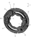
- hub 15 comprises a main body 40 connectable to input shaft 8 and an annular element 41 having an axis A and rigidly coupled at least to rotation to main body 40 e.g. by a splined connection ( figure 6 ).
- Annular element 41 defines at least one abutment 42, preferably two axis-symmetrical abutments extending axially towards turbine module 17.
- Such abutment is functionally equivalent to stop 10.
- turbine module 17 comprises a further annular element 43 rigidly connected to lateral wall 27 e.g. by bolts and rotatable with respect to hub 15.
- Annular element 43 of turbine module 17 defines an abutting surface 44, preferably two axis-symmetrical abutting surfaces, functionally equivalent to stop 11.
- Abutments 42 and abutting surfaces 44 extend along the axial direction so as to be circumferentially surrounded by isolator spiral spring 7. This improves compactness along the axial direction.
- Abutments 42 and abutting surfaces 44 define the maximum relative angular displacement between hub 15 and the combination of lock-up clutch module 19 and turbine module 17 in a first direction of rotation.
- annular elements 41 and 43 define respective further abutments 45 and abutting surfaces 46 to define the maximum relative angular displacement between hub 15 and the combination of lock-up clutch module 19 and turbine module 17 in a second direction of rotation.
- Annular element 41 further comprises at least a connecting portion 47, preferably two axis-symmetrical connecting portions, having a slot 48 to house in a force transmitting manner end portion 20 of isolator spiral spring 7.
- Slot 28 further defines a seat S to house an axial pin (an equivalent axial pin P is shown in figure 5 ) for securing end portion 20 to annular element 41.
- Axial dimension D1 of connection portion 47 is higher than axial dimension D2 of a portion 49 of annular element 41 facing abutting surfaces 44, 46 of annular element 43.
- each axis-symmetrical portion 49 defines a relative cut out 50, e.g. a through slot, angularly spaced from abutments 42, 45. Cut out 50 decreases the cross section loaded by impact forces generated by the interaction of abutments 42, 45 and abutting surfaces 44, 46.
- the increased compliance of portions 49 due to cut outs 50 helps to transform impact energy into elastic deformation and to avoid excessive load concentration within abutments 42, 45 so as to increase working life of the torque converter.
Landscapes
- Engineering & Computer Science (AREA)
- General Engineering & Computer Science (AREA)
- Mechanical Engineering (AREA)
- Physics & Mathematics (AREA)
- Acoustics & Sound (AREA)
- Aviation & Aerospace Engineering (AREA)
- Mechanical Operated Clutches (AREA)
- Electric Propulsion And Braking For Vehicles (AREA)
- Insulated Metal Substrates For Printed Circuits (AREA)
- Audible-Bandwidth Dynamoelectric Transducers Other Than Pickups (AREA)
Claims (15)
- Drehmomentwandleranordnung, umfassend eine Nabe (15) zur Verbindung mit einer Eingangswelle (8) eines Getriebes (G), einem Lock-up-Kupplungsmodul (19) zur selektiven Verbindung mit einer Kurbelwelle (2) eines internen Verbrennungsmotors (E), einem Turbinenmodul (17) eines Drehmomentwandlers (4), das starr mit dem Lock-up-Kupplungsmodul (19) verbunden und in Bezug auf die Nabe (15) drehbar ist, und ein Spiralfeder-Trennelement (7), um die Nabe (15) elastisch mit dem Lock-up-Kupplungsmodul (19) und dem Turbinenmodul (17) zu verbinden, wobei die Drehmomentwandleranordnung ein radiales Stützelement (18, 22) für das Turbinenmodul (17) auf der Nabe (15) umfasst,
wobei das radiale Stützelement (18, 22) radial in einer ringförmigen Aussparung (R) der Nabe (15) untergebracht ist,
dadurch gekennzeichnet, dass sie eine geformte Wand (23) umfasst, die das radiale Stützelement (18, 22) starr mit einem äußeren radialen Endabschnitt (21) des Schraubenfeder-Trennelements (7) verbindet. - Drehmomentwandleranordnung nach Anspruch 1, dadurch gekennzeichnet, dass sie einen ersten und einen zweiten Winkelanschlag (10, 11; 32, 33) zwischen der Nabe (15) und dem Lock-up-Kupplungsmodule (19) oder dem Turbinenmodul (17) umfasst, um Drehmoment zwischen dem Turbinenmodul (17) und der Nabe (15) oberhalb eines vordefinierten Drehmomentniveaus zu übertragen.
- Drehmomentwandler nach Anspruch 2, dadurch gekennzeichnet, dass der erste und der zweite Winkelanschlag (10, 11; 32, 33) so angeordnet sind, dass Drehmoment direkt von dem Lock-up-Kupplungsmodul (17) auf das Turbinenmodul (19) übertragen wird und das Spiralfeder-Trennelement (7) mit einem maximalen Drehmomentwert belastet wird, der definiert ist, wenn der erste und zweite Winkelanschlag (10, 11; 32, 33) aneinanderstoßen.
- Drehmomentwandler nach einem der Ansprüche 2 oder 3, dadurch gekennzeichnet, dass der erste und der zweite Anschlag (10, 11; 32, 33) entweder elastisch oder starr sind.
- Drehmomentwandler nach einem der Ansprüche 2 bis 4, dadurch gekennzeichnet, dass der erste und der zweite Anschlag (10, 11; 32, 33) von dem Feder-Trennelement (7) umgeben sind.
- Drehmomentwandleranordnung nach einem der Ansprüche 3 bis 5, dadurch gekennzeichnet, dass die Nabe (15) einen ersten Körper (34; 40) und einen ringförmigen Körper (35; 41) umfasst, der an einem Endabschnitt (20) des Schraubenfeder-Trennelements (7) befestigt ist und eine Achse (A) aufweist.
- Drehmomentwandleranordnung nach Anspruch 6, dadurch gekennzeichnet, dass der erste oder der zweite Anschlag (42) axial vom ringförmigen Körper (41) zum Turbinenmodul (17) ragt.
- Drehmomentwandleranordnung nach einem der Ansprüche 6 oder 7, dadurch gekennzeichnet, dass der ringförmige Körper (41) einen ersten Bereich (47) mit einer ersten axialen Abmessung und einen zweiten Bereich (49) mit einer zweiten axialen Abmessung umfasst, die geringer als die erste Abmessung ist, wobei der erste oder der zweite Anschlag (42) durch ein Widerlager zwischen dem ersten und dem zweiten Bereich definiert ist und der erste Bereich (47) kraftübertragend mit dem Schraubenfeder-Trennelement (7) verbunden ist.
- Drehmomentwandleranordnung nach Anspruch 8, dadurch gekennzeichnet, dass der zweite Bereich (49) einen Ausschnitt (50) definiert, wobei der Ausschnitt (50) winklig von dem Widerlager (42) verschoben ist.
- Drehmomentwandleranordnung nach einem der Ansprüche 6 bis 9, dadurch gekennzeichnet, dass sie eine Verzahnung zur Verbindung mit der Eingangswelle (8) aufweist.
- Drehmomentwandleranordnung nach Anspruch 6, dadurch gekennzeichnet, dass sie einen Ring (31) mit mindestens einem Vorsprung (32) umfasst, der den ersten oder den zweiten Winkelanschlag definiert.
- Drehmomentwandleranordnung nach Anspruch 11, dadurch gekennzeichnet, dass sich der Ring (31) auf der gleichen Seite des Lock-up-Kupplungsmoduls (17) in Bezug auf das Schraubenfeder-Trennelement (7) befindet.
- Drehmomentwandleranordnung nach einem der vorhergehenden Ansprüche, wobei das Spiralfeder-Trennelement (7) Spiralen aufweist, die einen Winkel zwischen 270° und 600° definieren.
- Drehmomentwandleranordnung nach einem der vorhergehenden Ansprüche, wobei das Spiralfeder-Trennelement (7) eine Spiralfeder mit einem Querschnittsgesamthöhen-/Breitenverhältnis zwischen 0,4 und 0,8 umfasst.
- Drehmomentwandleranordnung nach einem der vorhergehenden Ansprüche, wobei das Spiralfeder-Trennelement (7) eine Spiralfeder mit ebenen Flächen und Hohlkehlradius zwischen den ebenen Flächen zwischen 1 mm und 3 mm umfasst.
Applications Claiming Priority (2)
| Application Number | Priority Date | Filing Date | Title |
|---|---|---|---|
| IT000256A ITTO20120256A1 (it) | 2012-03-21 | 2012-03-21 | Gruppo convertitore di coppia per un veicolo |
| PCT/EP2013/056000 WO2013139944A1 (en) | 2012-03-21 | 2013-03-21 | Torque converter assembly for a vehicle |
Publications (2)
| Publication Number | Publication Date |
|---|---|
| EP2828554A1 EP2828554A1 (de) | 2015-01-28 |
| EP2828554B1 true EP2828554B1 (de) | 2019-12-18 |
Family
ID=46548725
Family Applications (1)
| Application Number | Title | Priority Date | Filing Date |
|---|---|---|---|
| EP13713809.5A Active EP2828554B1 (de) | 2012-03-21 | 2013-03-21 | Drehmomentwandlereinheit für ein fahrzeug |
Country Status (5)
| Country | Link |
|---|---|
| US (1) | US9447857B2 (de) |
| EP (1) | EP2828554B1 (de) |
| CN (1) | CN104583649B (de) |
| IT (1) | ITTO20120256A1 (de) |
| WO (1) | WO2013139944A1 (de) |
Families Citing this family (1)
| Publication number | Priority date | Publication date | Assignee | Title |
|---|---|---|---|---|
| FR3037626B1 (fr) * | 2015-06-18 | 2018-08-10 | Valeo Embrayages | Dispositif de filtration des vibrations |
Family Cites Families (10)
| Publication number | Priority date | Publication date | Assignee | Title |
|---|---|---|---|---|
| US4105102A (en) * | 1977-02-15 | 1978-08-08 | General Motors Corporation | Clutch and damper assembly |
| US4557357A (en) * | 1984-05-29 | 1985-12-10 | Eaton Corporation | Torsion damping mechanism with a viscous coupling |
| US5234376A (en) * | 1992-04-23 | 1993-08-10 | Eaton Corporation | Spiral spring of a torsional damper |
| DE10017801B4 (de) * | 2000-04-10 | 2012-11-08 | Zf Sachs Ag | Torsionsschwingungsdämpfer |
| DE10017743A1 (de) * | 2000-04-10 | 2001-10-11 | Mannesmann Sachs Ag | Freilaufanordnung, insbesondere für ein Leitrad eines hydrodynamischen Drehmomentwandlers |
| DE10152008B4 (de) * | 2001-10-22 | 2011-12-08 | Zf Sachs Ag | Hydraulische Kupplung mit einem Turbinentorsionsschwingungsdämpfer |
| DE10212281B4 (de) * | 2002-03-20 | 2011-12-22 | Zf Sachs Ag | Hydrodynamische Kopplungseinrichtung |
| JP4232905B2 (ja) * | 2005-04-13 | 2009-03-04 | ジヤトコ株式会社 | ロックアップダンパー装置 |
| DE112010004331B4 (de) * | 2009-11-09 | 2022-08-18 | Schaeffler Technologies AG & Co. KG | Hydrodynamischer Drehmomentwandler mit einem Drehschwingungsdämpfer |
| US8844691B2 (en) * | 2010-08-22 | 2014-09-30 | Schaeffler Technologies Gmbh & Co. Kg | Three-pass torque converters |
-
2012
- 2012-03-21 IT IT000256A patent/ITTO20120256A1/it unknown
-
2013
- 2013-03-21 EP EP13713809.5A patent/EP2828554B1/de active Active
- 2013-03-21 US US14/386,623 patent/US9447857B2/en not_active Expired - Fee Related
- 2013-03-21 CN CN201380024341.6A patent/CN104583649B/zh active Active
- 2013-03-21 WO PCT/EP2013/056000 patent/WO2013139944A1/en not_active Ceased
Non-Patent Citations (1)
| Title |
|---|
| None * |
Also Published As
| Publication number | Publication date |
|---|---|
| CN104583649A (zh) | 2015-04-29 |
| ITTO20120256A1 (it) | 2013-09-22 |
| US20150083538A1 (en) | 2015-03-26 |
| WO2013139944A1 (en) | 2013-09-26 |
| EP2828554A1 (de) | 2015-01-28 |
| CN104583649B (zh) | 2017-11-28 |
| US9447857B2 (en) | 2016-09-20 |
Similar Documents
| Publication | Publication Date | Title |
|---|---|---|
| KR101358998B1 (ko) | 차량용 토크 컨버터 | |
| US9909644B2 (en) | Tuned mass damper | |
| US8135525B2 (en) | Torque converter with turbine mass absorber | |
| US4795012A (en) | Spiral spring disc torsional coupling | |
| CN101398054B (zh) | 用于车辆传动装置的弹簧-质量阻尼器系统 | |
| US8439762B2 (en) | Torsional damper | |
| US11149817B2 (en) | Damper device | |
| JP2014152814A (ja) | トルクコンバータのロックアップ装置 | |
| JP2015520342A (ja) | 摩擦クラッチ組立体 | |
| JP3825219B2 (ja) | 流体式トルク伝達装置 | |
| EP0826899A2 (de) | Gleitlagerstütz in einem Zweimassenmechanismus für Kraftdurchleitung | |
| GB1594788A (en) | Torsional vibration damper | |
| KR100529868B1 (ko) | 토크 컨버터 | |
| CN212338025U (zh) | 用于驱动系的扭矩限制器、混合动力驱动系及混合动力车辆 | |
| US11454297B2 (en) | Torsional vibration damper | |
| US9447857B2 (en) | Torque converter assembly for a vehicle | |
| CN212536472U (zh) | 一种用于自动变速箱的液力冷却离合器 | |
| US20180202514A1 (en) | Torsional vibration damper for hydrodynamic torque converter, and torque converter including the same | |
| JPH07269650A (ja) | ねじれ遮断器アセンブリ | |
| JP7215983B2 (ja) | 動力伝達装置 | |
| KR102297696B1 (ko) | 차량용 토크 컨버터 | |
| CN112709797B (zh) | 具有扭转减振器的液力变矩器和包括其的机动车辆 | |
| KR101866937B1 (ko) | 차량용 토크 컨버터 | |
| KR101272881B1 (ko) | 차량용 토크 컨버터 | |
| EP2828548B1 (de) | Spiralfeder-zweimassenschwungrad mit paralleler konfiguration |
Legal Events
| Date | Code | Title | Description |
|---|---|---|---|
| PUAI | Public reference made under article 153(3) epc to a published international application that has entered the european phase |
Free format text: ORIGINAL CODE: 0009012 |
|
| 17P | Request for examination filed |
Effective date: 20140923 |
|
| AK | Designated contracting states |
Kind code of ref document: A1 Designated state(s): AL AT BE BG CH CY CZ DE DK EE ES FI FR GB GR HR HU IE IS IT LI LT LU LV MC MK MT NL NO PL PT RO RS SE SI SK SM TR |
|
| AX | Request for extension of the european patent |
Extension state: BA ME |
|
| DAX | Request for extension of the european patent (deleted) | ||
| GRAP | Despatch of communication of intention to grant a patent |
Free format text: ORIGINAL CODE: EPIDOSNIGR1 |
|
| STAA | Information on the status of an ep patent application or granted ep patent |
Free format text: STATUS: GRANT OF PATENT IS INTENDED |
|
| INTG | Intention to grant announced |
Effective date: 20190709 |
|
| GRAS | Grant fee paid |
Free format text: ORIGINAL CODE: EPIDOSNIGR3 |
|
| GRAA | (expected) grant |
Free format text: ORIGINAL CODE: 0009210 |
|
| STAA | Information on the status of an ep patent application or granted ep patent |
Free format text: STATUS: THE PATENT HAS BEEN GRANTED |
|
| AK | Designated contracting states |
Kind code of ref document: B1 Designated state(s): AL AT BE BG CH CY CZ DE DK EE ES FI FR GB GR HR HU IE IS IT LI LT LU LV MC MK MT NL NO PL PT RO RS SE SI SK SM TR |
|
| REG | Reference to a national code |
Ref country code: CH Ref legal event code: EP |
|
| REG | Reference to a national code |
Ref country code: DE Ref legal event code: R096 Ref document number: 602013064072 Country of ref document: DE |
|
| REG | Reference to a national code |
Ref country code: IE Ref legal event code: FG4D |
|
| REG | Reference to a national code |
Ref country code: AT Ref legal event code: REF Ref document number: 1214961 Country of ref document: AT Kind code of ref document: T Effective date: 20200115 |
|
| REG | Reference to a national code |
Ref country code: NL Ref legal event code: MP Effective date: 20191218 |
|
| PG25 | Lapsed in a contracting state [announced via postgrant information from national office to epo] |
Ref country code: LT Free format text: LAPSE BECAUSE OF FAILURE TO SUBMIT A TRANSLATION OF THE DESCRIPTION OR TO PAY THE FEE WITHIN THE PRESCRIBED TIME-LIMIT Effective date: 20191218 Ref country code: SE Free format text: LAPSE BECAUSE OF FAILURE TO SUBMIT A TRANSLATION OF THE DESCRIPTION OR TO PAY THE FEE WITHIN THE PRESCRIBED TIME-LIMIT Effective date: 20191218 Ref country code: LV Free format text: LAPSE BECAUSE OF FAILURE TO SUBMIT A TRANSLATION OF THE DESCRIPTION OR TO PAY THE FEE WITHIN THE PRESCRIBED TIME-LIMIT Effective date: 20191218 Ref country code: GR Free format text: LAPSE BECAUSE OF FAILURE TO SUBMIT A TRANSLATION OF THE DESCRIPTION OR TO PAY THE FEE WITHIN THE PRESCRIBED TIME-LIMIT Effective date: 20200319 Ref country code: NO Free format text: LAPSE BECAUSE OF FAILURE TO SUBMIT A TRANSLATION OF THE DESCRIPTION OR TO PAY THE FEE WITHIN THE PRESCRIBED TIME-LIMIT Effective date: 20200318 Ref country code: BG Free format text: LAPSE BECAUSE OF FAILURE TO SUBMIT A TRANSLATION OF THE DESCRIPTION OR TO PAY THE FEE WITHIN THE PRESCRIBED TIME-LIMIT Effective date: 20200318 Ref country code: FI Free format text: LAPSE BECAUSE OF FAILURE TO SUBMIT A TRANSLATION OF THE DESCRIPTION OR TO PAY THE FEE WITHIN THE PRESCRIBED TIME-LIMIT Effective date: 20191218 |
|
| REG | Reference to a national code |
Ref country code: LT Ref legal event code: MG4D |
|
| PG25 | Lapsed in a contracting state [announced via postgrant information from national office to epo] |
Ref country code: RS Free format text: LAPSE BECAUSE OF FAILURE TO SUBMIT A TRANSLATION OF THE DESCRIPTION OR TO PAY THE FEE WITHIN THE PRESCRIBED TIME-LIMIT Effective date: 20191218 Ref country code: HR Free format text: LAPSE BECAUSE OF FAILURE TO SUBMIT A TRANSLATION OF THE DESCRIPTION OR TO PAY THE FEE WITHIN THE PRESCRIBED TIME-LIMIT Effective date: 20191218 |
|
| PG25 | Lapsed in a contracting state [announced via postgrant information from national office to epo] |
Ref country code: AL Free format text: LAPSE BECAUSE OF FAILURE TO SUBMIT A TRANSLATION OF THE DESCRIPTION OR TO PAY THE FEE WITHIN THE PRESCRIBED TIME-LIMIT Effective date: 20191218 |
|
| PG25 | Lapsed in a contracting state [announced via postgrant information from national office to epo] |
Ref country code: CZ Free format text: LAPSE BECAUSE OF FAILURE TO SUBMIT A TRANSLATION OF THE DESCRIPTION OR TO PAY THE FEE WITHIN THE PRESCRIBED TIME-LIMIT Effective date: 20191218 Ref country code: RO Free format text: LAPSE BECAUSE OF FAILURE TO SUBMIT A TRANSLATION OF THE DESCRIPTION OR TO PAY THE FEE WITHIN THE PRESCRIBED TIME-LIMIT Effective date: 20191218 Ref country code: PT Free format text: LAPSE BECAUSE OF FAILURE TO SUBMIT A TRANSLATION OF THE DESCRIPTION OR TO PAY THE FEE WITHIN THE PRESCRIBED TIME-LIMIT Effective date: 20200513 Ref country code: EE Free format text: LAPSE BECAUSE OF FAILURE TO SUBMIT A TRANSLATION OF THE DESCRIPTION OR TO PAY THE FEE WITHIN THE PRESCRIBED TIME-LIMIT Effective date: 20191218 Ref country code: NL Free format text: LAPSE BECAUSE OF FAILURE TO SUBMIT A TRANSLATION OF THE DESCRIPTION OR TO PAY THE FEE WITHIN THE PRESCRIBED TIME-LIMIT Effective date: 20191218 |
|
| PG25 | Lapsed in a contracting state [announced via postgrant information from national office to epo] |
Ref country code: IS Free format text: LAPSE BECAUSE OF FAILURE TO SUBMIT A TRANSLATION OF THE DESCRIPTION OR TO PAY THE FEE WITHIN THE PRESCRIBED TIME-LIMIT Effective date: 20200418 Ref country code: SK Free format text: LAPSE BECAUSE OF FAILURE TO SUBMIT A TRANSLATION OF THE DESCRIPTION OR TO PAY THE FEE WITHIN THE PRESCRIBED TIME-LIMIT Effective date: 20191218 Ref country code: SM Free format text: LAPSE BECAUSE OF FAILURE TO SUBMIT A TRANSLATION OF THE DESCRIPTION OR TO PAY THE FEE WITHIN THE PRESCRIBED TIME-LIMIT Effective date: 20191218 |
|
| REG | Reference to a national code |
Ref country code: DE Ref legal event code: R097 Ref document number: 602013064072 Country of ref document: DE |
|
| REG | Reference to a national code |
Ref country code: AT Ref legal event code: MK05 Ref document number: 1214961 Country of ref document: AT Kind code of ref document: T Effective date: 20191218 |
|
| PLBE | No opposition filed within time limit |
Free format text: ORIGINAL CODE: 0009261 |
|
| STAA | Information on the status of an ep patent application or granted ep patent |
Free format text: STATUS: NO OPPOSITION FILED WITHIN TIME LIMIT |
|
| PG25 | Lapsed in a contracting state [announced via postgrant information from national office to epo] |
Ref country code: ES Free format text: LAPSE BECAUSE OF FAILURE TO SUBMIT A TRANSLATION OF THE DESCRIPTION OR TO PAY THE FEE WITHIN THE PRESCRIBED TIME-LIMIT Effective date: 20191218 Ref country code: MC Free format text: LAPSE BECAUSE OF FAILURE TO SUBMIT A TRANSLATION OF THE DESCRIPTION OR TO PAY THE FEE WITHIN THE PRESCRIBED TIME-LIMIT Effective date: 20191218 Ref country code: DK Free format text: LAPSE BECAUSE OF FAILURE TO SUBMIT A TRANSLATION OF THE DESCRIPTION OR TO PAY THE FEE WITHIN THE PRESCRIBED TIME-LIMIT Effective date: 20191218 |
|
| REG | Reference to a national code |
Ref country code: CH Ref legal event code: PL |
|
| 26N | No opposition filed |
Effective date: 20200921 |
|
| PG25 | Lapsed in a contracting state [announced via postgrant information from national office to epo] |
Ref country code: SI Free format text: LAPSE BECAUSE OF FAILURE TO SUBMIT A TRANSLATION OF THE DESCRIPTION OR TO PAY THE FEE WITHIN THE PRESCRIBED TIME-LIMIT Effective date: 20191218 Ref country code: AT Free format text: LAPSE BECAUSE OF FAILURE TO SUBMIT A TRANSLATION OF THE DESCRIPTION OR TO PAY THE FEE WITHIN THE PRESCRIBED TIME-LIMIT Effective date: 20191218 |
|
| REG | Reference to a national code |
Ref country code: BE Ref legal event code: MM Effective date: 20200331 |
|
| PG25 | Lapsed in a contracting state [announced via postgrant information from national office to epo] |
Ref country code: LU Free format text: LAPSE BECAUSE OF NON-PAYMENT OF DUE FEES Effective date: 20200321 |
|
| PG25 | Lapsed in a contracting state [announced via postgrant information from national office to epo] |
Ref country code: CH Free format text: LAPSE BECAUSE OF NON-PAYMENT OF DUE FEES Effective date: 20200331 Ref country code: FR Free format text: LAPSE BECAUSE OF NON-PAYMENT OF DUE FEES Effective date: 20200331 Ref country code: LI Free format text: LAPSE BECAUSE OF NON-PAYMENT OF DUE FEES Effective date: 20200331 Ref country code: IT Free format text: LAPSE BECAUSE OF FAILURE TO SUBMIT A TRANSLATION OF THE DESCRIPTION OR TO PAY THE FEE WITHIN THE PRESCRIBED TIME-LIMIT Effective date: 20191218 Ref country code: IE Free format text: LAPSE BECAUSE OF NON-PAYMENT OF DUE FEES Effective date: 20200321 |
|
| PG25 | Lapsed in a contracting state [announced via postgrant information from national office to epo] |
Ref country code: PL Free format text: LAPSE BECAUSE OF FAILURE TO SUBMIT A TRANSLATION OF THE DESCRIPTION OR TO PAY THE FEE WITHIN THE PRESCRIBED TIME-LIMIT Effective date: 20191218 Ref country code: BE Free format text: LAPSE BECAUSE OF NON-PAYMENT OF DUE FEES Effective date: 20200331 |
|
| GBPC | Gb: european patent ceased through non-payment of renewal fee |
Effective date: 20200321 |
|
| PG25 | Lapsed in a contracting state [announced via postgrant information from national office to epo] |
Ref country code: GB Free format text: LAPSE BECAUSE OF NON-PAYMENT OF DUE FEES Effective date: 20200321 |
|
| PG25 | Lapsed in a contracting state [announced via postgrant information from national office to epo] |
Ref country code: TR Free format text: LAPSE BECAUSE OF FAILURE TO SUBMIT A TRANSLATION OF THE DESCRIPTION OR TO PAY THE FEE WITHIN THE PRESCRIBED TIME-LIMIT Effective date: 20191218 Ref country code: MT Free format text: LAPSE BECAUSE OF FAILURE TO SUBMIT A TRANSLATION OF THE DESCRIPTION OR TO PAY THE FEE WITHIN THE PRESCRIBED TIME-LIMIT Effective date: 20191218 Ref country code: CY Free format text: LAPSE BECAUSE OF FAILURE TO SUBMIT A TRANSLATION OF THE DESCRIPTION OR TO PAY THE FEE WITHIN THE PRESCRIBED TIME-LIMIT Effective date: 20191218 |
|
| PG25 | Lapsed in a contracting state [announced via postgrant information from national office to epo] |
Ref country code: MK Free format text: LAPSE BECAUSE OF FAILURE TO SUBMIT A TRANSLATION OF THE DESCRIPTION OR TO PAY THE FEE WITHIN THE PRESCRIBED TIME-LIMIT Effective date: 20191218 |
|
| P01 | Opt-out of the competence of the unified patent court (upc) registered |
Effective date: 20230505 |
|
| REG | Reference to a national code |
Ref country code: DE Ref legal event code: R081 Ref document number: 602013064072 Country of ref document: DE Owner name: PROPULSION SOLUTIONS S.R.L., IVREA, IT Free format text: FORMER OWNER: DAYCO EUROPE S.R.L., CHIETI, IT Ref country code: DE Ref legal event code: R081 Ref document number: 602013064072 Country of ref document: DE Owner name: MUVIQ S.R.L., IVREA, IT Free format text: FORMER OWNER: DAYCO EUROPE S.R.L., CHIETI, IT |
|
| PGFP | Annual fee paid to national office [announced via postgrant information from national office to epo] |
Ref country code: DE Payment date: 20250327 Year of fee payment: 13 |
|
| REG | Reference to a national code |
Ref country code: DE Ref legal event code: R081 Ref document number: 602013064072 Country of ref document: DE Owner name: MUVIQ S.R.L., IVREA, IT Free format text: FORMER OWNER: PROPULSION SOLUTIONS S.R.L., IVREA, TO, IT |