EP2828502B1 - Apparatus and method for oxy-combustion of fuels in internal combustion engines - Google Patents
Apparatus and method for oxy-combustion of fuels in internal combustion engines Download PDFInfo
- Publication number
- EP2828502B1 EP2828502B1 EP13714803.7A EP13714803A EP2828502B1 EP 2828502 B1 EP2828502 B1 EP 2828502B1 EP 13714803 A EP13714803 A EP 13714803A EP 2828502 B1 EP2828502 B1 EP 2828502B1
- Authority
- EP
- European Patent Office
- Prior art keywords
- oxygen
- air
- ice
- engine
- membrane
- Prior art date
- Legal status (The legal status is an assumption and is not a legal conclusion. Google has not performed a legal analysis and makes no representation as to the accuracy of the status listed.)
- Not-in-force
Links
Images


Classifications
-
- F—MECHANICAL ENGINEERING; LIGHTING; HEATING; WEAPONS; BLASTING
- F02—COMBUSTION ENGINES; HOT-GAS OR COMBUSTION-PRODUCT ENGINE PLANTS
- F02M—SUPPLYING COMBUSTION ENGINES IN GENERAL WITH COMBUSTIBLE MIXTURES OR CONSTITUENTS THEREOF
- F02M25/00—Engine-pertinent apparatus for adding non-fuel substances or small quantities of secondary fuel to combustion-air, main fuel or fuel-air mixture
- F02M25/10—Engine-pertinent apparatus for adding non-fuel substances or small quantities of secondary fuel to combustion-air, main fuel or fuel-air mixture adding acetylene, non-waterborne hydrogen, non-airborne oxygen, or ozone
- F02M25/12—Engine-pertinent apparatus for adding non-fuel substances or small quantities of secondary fuel to combustion-air, main fuel or fuel-air mixture adding acetylene, non-waterborne hydrogen, non-airborne oxygen, or ozone the apparatus having means for generating such gases
-
- B—PERFORMING OPERATIONS; TRANSPORTING
- B01—PHYSICAL OR CHEMICAL PROCESSES OR APPARATUS IN GENERAL
- B01D—SEPARATION
- B01D53/00—Separation of gases or vapours; Recovering vapours of volatile solvents from gases; Chemical or biological purification of waste gases, e.g. engine exhaust gases, smoke, fumes, flue gases, aerosols
- B01D53/02—Separation of gases or vapours; Recovering vapours of volatile solvents from gases; Chemical or biological purification of waste gases, e.g. engine exhaust gases, smoke, fumes, flue gases, aerosols by adsorption, e.g. preparative gas chromatography
- B01D53/04—Separation of gases or vapours; Recovering vapours of volatile solvents from gases; Chemical or biological purification of waste gases, e.g. engine exhaust gases, smoke, fumes, flue gases, aerosols by adsorption, e.g. preparative gas chromatography with stationary adsorbents
- B01D53/0462—Temperature swing adsorption
-
- B—PERFORMING OPERATIONS; TRANSPORTING
- B01—PHYSICAL OR CHEMICAL PROCESSES OR APPARATUS IN GENERAL
- B01D—SEPARATION
- B01D53/00—Separation of gases or vapours; Recovering vapours of volatile solvents from gases; Chemical or biological purification of waste gases, e.g. engine exhaust gases, smoke, fumes, flue gases, aerosols
- B01D53/02—Separation of gases or vapours; Recovering vapours of volatile solvents from gases; Chemical or biological purification of waste gases, e.g. engine exhaust gases, smoke, fumes, flue gases, aerosols by adsorption, e.g. preparative gas chromatography
- B01D53/04—Separation of gases or vapours; Recovering vapours of volatile solvents from gases; Chemical or biological purification of waste gases, e.g. engine exhaust gases, smoke, fumes, flue gases, aerosols by adsorption, e.g. preparative gas chromatography with stationary adsorbents
- B01D53/047—Pressure swing adsorption
- B01D53/0476—Vacuum pressure swing adsorption
-
- B—PERFORMING OPERATIONS; TRANSPORTING
- B01—PHYSICAL OR CHEMICAL PROCESSES OR APPARATUS IN GENERAL
- B01D—SEPARATION
- B01D53/00—Separation of gases or vapours; Recovering vapours of volatile solvents from gases; Chemical or biological purification of waste gases, e.g. engine exhaust gases, smoke, fumes, flue gases, aerosols
- B01D53/22—Separation of gases or vapours; Recovering vapours of volatile solvents from gases; Chemical or biological purification of waste gases, e.g. engine exhaust gases, smoke, fumes, flue gases, aerosols by diffusion
-
- C—CHEMISTRY; METALLURGY
- C01—INORGANIC CHEMISTRY
- C01B—NON-METALLIC ELEMENTS; COMPOUNDS THEREOF; METALLOIDS OR COMPOUNDS THEREOF NOT COVERED BY SUBCLASS C01C
- C01B13/00—Oxygen; Ozone; Oxides or hydroxides in general
- C01B13/02—Preparation of oxygen
- C01B13/0229—Purification or separation processes
- C01B13/0248—Physical processing only
- C01B13/0251—Physical processing only by making use of membranes
- C01B13/0255—Physical processing only by making use of membranes characterised by the type of membrane
-
- C—CHEMISTRY; METALLURGY
- C01—INORGANIC CHEMISTRY
- C01B—NON-METALLIC ELEMENTS; COMPOUNDS THEREOF; METALLOIDS OR COMPOUNDS THEREOF NOT COVERED BY SUBCLASS C01C
- C01B13/00—Oxygen; Ozone; Oxides or hydroxides in general
- C01B13/02—Preparation of oxygen
- C01B13/0229—Purification or separation processes
- C01B13/0248—Physical processing only
- C01B13/0259—Physical processing only by adsorption on solids
-
- F—MECHANICAL ENGINEERING; LIGHTING; HEATING; WEAPONS; BLASTING
- F02—COMBUSTION ENGINES; HOT-GAS OR COMBUSTION-PRODUCT ENGINE PLANTS
- F02B—INTERNAL-COMBUSTION PISTON ENGINES; COMBUSTION ENGINES IN GENERAL
- F02B47/00—Methods of operating engines involving adding non-fuel substances or anti-knock agents to combustion air, fuel, or fuel-air mixtures of engines
- F02B47/04—Methods of operating engines involving adding non-fuel substances or anti-knock agents to combustion air, fuel, or fuel-air mixtures of engines the substances being other than water or steam only
- F02B47/08—Methods of operating engines involving adding non-fuel substances or anti-knock agents to combustion air, fuel, or fuel-air mixtures of engines the substances being other than water or steam only the substances including exhaust gas
- F02B47/10—Circulation of exhaust gas in closed or semi-closed circuits, e.g. with simultaneous addition of oxygen
-
- F—MECHANICAL ENGINEERING; LIGHTING; HEATING; WEAPONS; BLASTING
- F02—COMBUSTION ENGINES; HOT-GAS OR COMBUSTION-PRODUCT ENGINE PLANTS
- F02B—INTERNAL-COMBUSTION PISTON ENGINES; COMBUSTION ENGINES IN GENERAL
- F02B77/00—Component parts, details or accessories, not otherwise provided for
-
- F—MECHANICAL ENGINEERING; LIGHTING; HEATING; WEAPONS; BLASTING
- F02—COMBUSTION ENGINES; HOT-GAS OR COMBUSTION-PRODUCT ENGINE PLANTS
- F02B—INTERNAL-COMBUSTION PISTON ENGINES; COMBUSTION ENGINES IN GENERAL
- F02B77/00—Component parts, details or accessories, not otherwise provided for
- F02B77/02—Surface coverings of combustion-gas-swept parts
-
- F—MECHANICAL ENGINEERING; LIGHTING; HEATING; WEAPONS; BLASTING
- F02—COMBUSTION ENGINES; HOT-GAS OR COMBUSTION-PRODUCT ENGINE PLANTS
- F02M—SUPPLYING COMBUSTION ENGINES IN GENERAL WITH COMBUSTIBLE MIXTURES OR CONSTITUENTS THEREOF
- F02M26/00—Engine-pertinent apparatus for adding exhaust gases to combustion-air, main fuel or fuel-air mixture, e.g. by exhaust gas recirculation [EGR] systems
- F02M26/02—EGR systems specially adapted for supercharged engines
- F02M26/04—EGR systems specially adapted for supercharged engines with a single turbocharger
-
- F—MECHANICAL ENGINEERING; LIGHTING; HEATING; WEAPONS; BLASTING
- F02—COMBUSTION ENGINES; HOT-GAS OR COMBUSTION-PRODUCT ENGINE PLANTS
- F02M—SUPPLYING COMBUSTION ENGINES IN GENERAL WITH COMBUSTIBLE MIXTURES OR CONSTITUENTS THEREOF
- F02M26/00—Engine-pertinent apparatus for adding exhaust gases to combustion-air, main fuel or fuel-air mixture, e.g. by exhaust gas recirculation [EGR] systems
- F02M26/13—Arrangement or layout of EGR passages, e.g. in relation to specific engine parts or for incorporation of accessories
- F02M26/35—Arrangement or layout of EGR passages, e.g. in relation to specific engine parts or for incorporation of accessories with means for cleaning or treating the recirculated gases, e.g. catalysts, condensate traps, particle filters or heaters
-
- F—MECHANICAL ENGINEERING; LIGHTING; HEATING; WEAPONS; BLASTING
- F02—COMBUSTION ENGINES; HOT-GAS OR COMBUSTION-PRODUCT ENGINE PLANTS
- F02M—SUPPLYING COMBUSTION ENGINES IN GENERAL WITH COMBUSTIBLE MIXTURES OR CONSTITUENTS THEREOF
- F02M26/00—Engine-pertinent apparatus for adding exhaust gases to combustion-air, main fuel or fuel-air mixture, e.g. by exhaust gas recirculation [EGR] systems
- F02M26/13—Arrangement or layout of EGR passages, e.g. in relation to specific engine parts or for incorporation of accessories
- F02M26/37—Arrangement or layout of EGR passages, e.g. in relation to specific engine parts or for incorporation of accessories with temporary storage of recirculated exhaust gas
-
- F—MECHANICAL ENGINEERING; LIGHTING; HEATING; WEAPONS; BLASTING
- F02—COMBUSTION ENGINES; HOT-GAS OR COMBUSTION-PRODUCT ENGINE PLANTS
- F02M—SUPPLYING COMBUSTION ENGINES IN GENERAL WITH COMBUSTIBLE MIXTURES OR CONSTITUENTS THEREOF
- F02M35/00—Combustion-air cleaners, air intakes, intake silencers, or induction systems specially adapted for, or arranged on, internal-combustion engines
- F02M35/10—Air intakes; Induction systems
- F02M35/10242—Devices or means connected to or integrated into air intakes; Air intakes combined with other engine or vehicle parts
-
- F—MECHANICAL ENGINEERING; LIGHTING; HEATING; WEAPONS; BLASTING
- F02—COMBUSTION ENGINES; HOT-GAS OR COMBUSTION-PRODUCT ENGINE PLANTS
- F02M—SUPPLYING COMBUSTION ENGINES IN GENERAL WITH COMBUSTIBLE MIXTURES OR CONSTITUENTS THEREOF
- F02M35/00—Combustion-air cleaners, air intakes, intake silencers, or induction systems specially adapted for, or arranged on, internal-combustion engines
- F02M35/10—Air intakes; Induction systems
- F02M35/10373—Sensors for intake systems
-
- B—PERFORMING OPERATIONS; TRANSPORTING
- B01—PHYSICAL OR CHEMICAL PROCESSES OR APPARATUS IN GENERAL
- B01D—SEPARATION
- B01D2253/00—Adsorbents used in seperation treatment of gases and vapours
- B01D2253/10—Inorganic adsorbents
- B01D2253/112—Metals or metal compounds not provided for in B01D2253/104 or B01D2253/106
- B01D2253/1124—Metal oxides
-
- B—PERFORMING OPERATIONS; TRANSPORTING
- B01—PHYSICAL OR CHEMICAL PROCESSES OR APPARATUS IN GENERAL
- B01D—SEPARATION
- B01D2256/00—Main component in the product gas stream after treatment
- B01D2256/10—Nitrogen
-
- B—PERFORMING OPERATIONS; TRANSPORTING
- B01—PHYSICAL OR CHEMICAL PROCESSES OR APPARATUS IN GENERAL
- B01D—SEPARATION
- B01D2256/00—Main component in the product gas stream after treatment
- B01D2256/12—Oxygen
-
- B—PERFORMING OPERATIONS; TRANSPORTING
- B01—PHYSICAL OR CHEMICAL PROCESSES OR APPARATUS IN GENERAL
- B01D—SEPARATION
- B01D2257/00—Components to be removed
- B01D2257/10—Single element gases other than halogens
- B01D2257/102—Nitrogen
-
- B—PERFORMING OPERATIONS; TRANSPORTING
- B01—PHYSICAL OR CHEMICAL PROCESSES OR APPARATUS IN GENERAL
- B01D—SEPARATION
- B01D2257/00—Components to be removed
- B01D2257/10—Single element gases other than halogens
- B01D2257/104—Oxygen
-
- B—PERFORMING OPERATIONS; TRANSPORTING
- B01—PHYSICAL OR CHEMICAL PROCESSES OR APPARATUS IN GENERAL
- B01D—SEPARATION
- B01D2257/00—Components to be removed
- B01D2257/80—Water
-
- B—PERFORMING OPERATIONS; TRANSPORTING
- B01—PHYSICAL OR CHEMICAL PROCESSES OR APPARATUS IN GENERAL
- B01D—SEPARATION
- B01D2259/00—Type of treatment
- B01D2259/40—Further details for adsorption processes and devices
- B01D2259/402—Further details for adsorption processes and devices using two beds
-
- B—PERFORMING OPERATIONS; TRANSPORTING
- B01—PHYSICAL OR CHEMICAL PROCESSES OR APPARATUS IN GENERAL
- B01D—SEPARATION
- B01D2259/00—Type of treatment
- B01D2259/45—Gas separation or purification devices adapted for specific applications
-
- B—PERFORMING OPERATIONS; TRANSPORTING
- B01—PHYSICAL OR CHEMICAL PROCESSES OR APPARATUS IN GENERAL
- B01D—SEPARATION
- B01D53/00—Separation of gases or vapours; Recovering vapours of volatile solvents from gases; Chemical or biological purification of waste gases, e.g. engine exhaust gases, smoke, fumes, flue gases, aerosols
- B01D53/02—Separation of gases or vapours; Recovering vapours of volatile solvents from gases; Chemical or biological purification of waste gases, e.g. engine exhaust gases, smoke, fumes, flue gases, aerosols by adsorption, e.g. preparative gas chromatography
- B01D53/04—Separation of gases or vapours; Recovering vapours of volatile solvents from gases; Chemical or biological purification of waste gases, e.g. engine exhaust gases, smoke, fumes, flue gases, aerosols by adsorption, e.g. preparative gas chromatography with stationary adsorbents
- B01D53/047—Pressure swing adsorption
-
- C—CHEMISTRY; METALLURGY
- C01—INORGANIC CHEMISTRY
- C01B—NON-METALLIC ELEMENTS; COMPOUNDS THEREOF; METALLOIDS OR COMPOUNDS THEREOF NOT COVERED BY SUBCLASS C01C
- C01B2210/00—Purification or separation of specific gases
- C01B2210/0043—Impurity removed
- C01B2210/0046—Nitrogen
-
- C—CHEMISTRY; METALLURGY
- C01—INORGANIC CHEMISTRY
- C01B—NON-METALLIC ELEMENTS; COMPOUNDS THEREOF; METALLOIDS OR COMPOUNDS THEREOF NOT COVERED BY SUBCLASS C01C
- C01B2210/00—Purification or separation of specific gases
- C01B2210/0043—Impurity removed
- C01B2210/0051—Carbon dioxide
-
- C—CHEMISTRY; METALLURGY
- C01—INORGANIC CHEMISTRY
- C01B—NON-METALLIC ELEMENTS; COMPOUNDS THEREOF; METALLOIDS OR COMPOUNDS THEREOF NOT COVERED BY SUBCLASS C01C
- C01B2210/00—Purification or separation of specific gases
- C01B2210/0043—Impurity removed
- C01B2210/0075—Nitrogen oxides
-
- F—MECHANICAL ENGINEERING; LIGHTING; HEATING; WEAPONS; BLASTING
- F02—COMBUSTION ENGINES; HOT-GAS OR COMBUSTION-PRODUCT ENGINE PLANTS
- F02B—INTERNAL-COMBUSTION PISTON ENGINES; COMBUSTION ENGINES IN GENERAL
- F02B37/00—Engines characterised by provision of pumps driven at least for part of the time by exhaust
-
- Y—GENERAL TAGGING OF NEW TECHNOLOGICAL DEVELOPMENTS; GENERAL TAGGING OF CROSS-SECTIONAL TECHNOLOGIES SPANNING OVER SEVERAL SECTIONS OF THE IPC; TECHNICAL SUBJECTS COVERED BY FORMER USPC CROSS-REFERENCE ART COLLECTIONS [XRACs] AND DIGESTS
- Y02—TECHNOLOGIES OR APPLICATIONS FOR MITIGATION OR ADAPTATION AGAINST CLIMATE CHANGE
- Y02C—CAPTURE, STORAGE, SEQUESTRATION OR DISPOSAL OF GREENHOUSE GASES [GHG]
- Y02C20/00—Capture or disposal of greenhouse gases
- Y02C20/40—Capture or disposal of greenhouse gases of CO2
-
- Y—GENERAL TAGGING OF NEW TECHNOLOGICAL DEVELOPMENTS; GENERAL TAGGING OF CROSS-SECTIONAL TECHNOLOGIES SPANNING OVER SEVERAL SECTIONS OF THE IPC; TECHNICAL SUBJECTS COVERED BY FORMER USPC CROSS-REFERENCE ART COLLECTIONS [XRACs] AND DIGESTS
- Y02—TECHNOLOGIES OR APPLICATIONS FOR MITIGATION OR ADAPTATION AGAINST CLIMATE CHANGE
- Y02P—CLIMATE CHANGE MITIGATION TECHNOLOGIES IN THE PRODUCTION OR PROCESSING OF GOODS
- Y02P20/00—Technologies relating to chemical industry
- Y02P20/10—Process efficiency
- Y02P20/129—Energy recovery, e.g. by cogeneration, H2recovery or pressure recovery turbines
-
- Y—GENERAL TAGGING OF NEW TECHNOLOGICAL DEVELOPMENTS; GENERAL TAGGING OF CROSS-SECTIONAL TECHNOLOGIES SPANNING OVER SEVERAL SECTIONS OF THE IPC; TECHNICAL SUBJECTS COVERED BY FORMER USPC CROSS-REFERENCE ART COLLECTIONS [XRACs] AND DIGESTS
- Y02—TECHNOLOGIES OR APPLICATIONS FOR MITIGATION OR ADAPTATION AGAINST CLIMATE CHANGE
- Y02P—CLIMATE CHANGE MITIGATION TECHNOLOGIES IN THE PRODUCTION OR PROCESSING OF GOODS
- Y02P20/00—Technologies relating to chemical industry
- Y02P20/151—Reduction of greenhouse gas [GHG] emissions, e.g. CO2
-
- Y—GENERAL TAGGING OF NEW TECHNOLOGICAL DEVELOPMENTS; GENERAL TAGGING OF CROSS-SECTIONAL TECHNOLOGIES SPANNING OVER SEVERAL SECTIONS OF THE IPC; TECHNICAL SUBJECTS COVERED BY FORMER USPC CROSS-REFERENCE ART COLLECTIONS [XRACs] AND DIGESTS
- Y02—TECHNOLOGIES OR APPLICATIONS FOR MITIGATION OR ADAPTATION AGAINST CLIMATE CHANGE
- Y02P—CLIMATE CHANGE MITIGATION TECHNOLOGIES IN THE PRODUCTION OR PROCESSING OF GOODS
- Y02P30/00—Technologies relating to oil refining and petrochemical industry
-
- Y—GENERAL TAGGING OF NEW TECHNOLOGICAL DEVELOPMENTS; GENERAL TAGGING OF CROSS-SECTIONAL TECHNOLOGIES SPANNING OVER SEVERAL SECTIONS OF THE IPC; TECHNICAL SUBJECTS COVERED BY FORMER USPC CROSS-REFERENCE ART COLLECTIONS [XRACs] AND DIGESTS
- Y02—TECHNOLOGIES OR APPLICATIONS FOR MITIGATION OR ADAPTATION AGAINST CLIMATE CHANGE
- Y02T—CLIMATE CHANGE MITIGATION TECHNOLOGIES RELATED TO TRANSPORTATION
- Y02T10/00—Road transport of goods or passengers
- Y02T10/10—Internal combustion engine [ICE] based vehicles
- Y02T10/12—Improving ICE efficiencies
Definitions
- This invention relates to the elimination or reduction of nitrogen following the intake of atmospheric air in an internal combustion engine.
- an air separation plant use a membrane-based air separation system to separate the air into its component parts by passing an air feedstream under pressure over a membrane.
- the pressure gradient across the membrane causes the most permeable components to pass through the membrane more rapidly than other components, thereby producing a product stream that is enriched in the permeate component, while the original feedstream is depleted in that component.
- Many membranes can operate at ambient temperatures. Several types of membranes and their characteristics are described. Cellulose acetate membranes are said to exhibit good separation factors for oxygen and nitrogen, but have relatively low flux rates. Film composite membranes placed over a microporous polysulfone substrate exhibit lower separation factors than cellulose acetate, but have higher flux rates at the same pressure differential. Providing multiple membranes in series can increase the oxygen concentration in the product stream.
- Electroceramic membranes which are ionic solid solutions that permit movement of ions, require relatively higher temperatures of about 800°F to mobilize the oxide ion when separating oxygen from the air feedstream.
- the combustion exhaust gas referred to as the "working fluid” is routed to a heat exchanger which in turn heats the electroceramic membrane to the desired operating temperature of 800°F.
- the patent identifies yttria stabilized zirconia as a possible material for the electroceramic membrane.
- the '264 patent also contemplates that a membrane could be used to pass nitrogen and thereby reduce the nitrogen content of the remaining air feedstream.
- the nitrogen enriched stream will be on the outlet side of the membrane and the oxygen-enriched stream will be the retentate. Since the rate of diffusion through the membrane is determined by ion mobility, which in turn is a characteristic of a particular material and is dependent on the size, charge and geometry of the cations in the lattice, the geometry and location of the electroceramic membrane(s) will be determined by its mode of operation.
- USP 5,051,113 discloses an air intake system for mobile engines that utilizes a selectively permeable membrane to effect oxygen enrichment of the air entering the engine intake in order to improve engine efficiency.
- the disclosure of USP 5,051,113 is incorporated herein by reference.
- the system utilizes a perfluorodioxole membrane that has an oxygen/nitrogen selectivity of at least 1.4:1 and provides from about a 10% to a maximum of 66% increase in O 2 under optimum conditions, and otherwise from about 10% to 30% increase of O 2 in the intake gas.
- the '113 patent's oxygen enrichment process does not eliminate the majority of the NO x pollutants.
- a major problem associated with use of the oxy-combustion process in motor vehicles powered by internal combustion engines is how to minimize the additional weight and space required by the air separation components that are disclosed as necessary for the practice of the process by the prior art, e.g., the '264 patent.
- size and weight of the additional apparatus required for the step of cycling of exhaust gases through a heat exchanger in order to achieve the 800°F operating temperature for the electroceramic membrane will be seen by the automotive designer concerned with miles per gallon ratings and vehicle weight to be a significant disadvantage of that process.
- one problem to be solved is how to achieve the known advantages of oxy-combustion in an ICE used to power a motor vehicle, while minimizing adverse effects on the overall efficient operation of the motor vehicle that are associated with the increase in weight of additional components and the power requirements associated with the air separation step.
- GB 2,349,175 A describes combustion of pyrolysis oil and oxygen-enriched air in compression-ignition engines.
- FR 2,952,406 A3 describes a drive train for a motor vehicle.
- US 5,636,619 A discloses an internal combustion engine with an air intake system comprising a first air flow means and a second air flow means, the second air flow means comprising an oxygen enrichment membrane.
- the present invention provides a method and apparatus for the oxy-combustion of fuel in an ICE used to power a vehicle which method uses free energy available onboard the vehicle in the form of waste heat to separate oxygen from air, eliminate or significantly reduce the volume of nitrogen entering the combustion chamber, and thereby provide a corresponding reduction in NO x pollutants released into the atmosphere.
- the invention is integrated with a method and apparatus to capture CO 2 from the engine exhaust stream, which is now low in nitrogen and contains a very low level of NO x gases, and to increase the density of the CO 2 for temporary storage until it is discharged at a recovery station, e.g., during vehicle refueling.
- Oxygen is separated from air and combusted with fuel to produce pure or almost pure exhaust products of CO 2 and water (H 2 O).
- the H 2 O can readily be condensed and separated before the CO 2 is densified and temporarily stored onboard the vehicle.
- the approach of combusting oxygen with fuel is referred to as oxy-combustion and various technologies are available for the separation of O 2 from atmospheric air.
- ITMs ion transport membranes
- Ceramatec, Inc. of Salt Lake City, Utah, USA The ITMs are used to separate high-purity oxygen from atmospheric air. Air Products and Chemicals, Inc. of Allentown, Pennsylvania, USA is also engaged in the commercialization of the ITM oxygen separation process.
- the ceramic oxygen generator is a portable oxygen generator that uses a solid ceramic electrolyte positioned between two porous electrodes to produce oxygen.
- the ceramic membrane is heated to approximately 700°C.
- the cells are also able to produce oxygen at above their rated design capacity by increasing the operating temperature and the electrical potential applied.
- the electrolyte assembly for use in a solid electrochemical membrane oxygen separation cell having improved performance characteristic is described in USP 5,021,137 , assigned to Ceramatec, Inc., the disclosure of which is incorporated herein by reference.
- the electrolyte includes cerium oxide, or ceria, doped with calcium oxide, strontium oxide or yttrium oxide, with a pair of electrodes of sintered lanthanum strontium cobalite covered with a thin layer of silver.
- This system is based on the infinite selectivity of oxygen ion migration through a dense solid ceramic electrolyte membrane under the influence of an externally applied electrical potential.
- the solid electrolyte is formed from cerium oxide with dopants added to enhance both ion transport and membrane processability.
- the oxidation and reduction reactions are promoted by the use of porous perovskite electrodes, which together with the planar ceramic electrolytic membrane elements form an electrochemical cell; a plurality of cells are combined to form a stack.
- Stacks comprising multiple cells in a planar configuration provide excellent electrochemical performance and stability, mechanical integrity and the capacity to produce high-purity oxygen over thousands of hours of use.
- the oxygen generator system based on ion transport membranes includes an integrated thermal management system, air mover, power supply and associated control systems.
- thermal management includes insulating the stack(s) from the local environment to maintain the required operating temperature of the cell in order to minimize the electrical power used for heating.
- a high efficiency heat recovery device is utilized to recover the energy value from the heat of the depleted exhaust air and from the oxygen. By recovering the heat energy, the electrical power consumption can be minimized.
- the solid electrolyte ceramic membrane can be supported by a nickel superalloy matrix to make the oxygen generator cells much less prone to cracking due to the forces of expansion and contraction associated with the heating and cooling of the stacks during start-up and shutdown of the ICE.
- An air separation process that can be utilized in the practice of the invention is based upon an oxygen capture and storage process which utilizes a solid adsorbent that removes and retains O 2 from atmospheric air passing over a fixed or fluidized bed operating at an initial temperature.
- a sweep gas is passed over the bed to release the adsorbed oxygen.
- Two or more adsorbent beds can be operated in parallel, with one or more beds adsorbing oxygen and the remaining bed or beds being subjected to recovery of essentially pure oxygen mixed with the sweep gas.
- One such system is available from the Linde Group and is referred to as the Ceramic Autothermal Recovery (CAR) oxygen generation process.
- CAR Ceramic Autothermal Recovery
- the sweep gas can be a portion of the hot exhaust gases from the ICE which are principally CO 2 and water vapor.
- the sweep gas can be diverted from the exhaust stream and enter the cylinder with the fuel.
- a portion of the exhaust gas stream, including water vapor, can be recycled with the fuel mixture to control the temperature of the engine in accordance with exhaust gas recycling (EGR) methods and apparatus that are well known in the art.
- EGR exhaust gas recycling
- a nitrogen generator sold by the Parker Bolston division of Parker Hannifin Corporation utilizes membranes which separate compressed air into a stream containing 95-99% pure nitrogen as the retentate.
- the semi-permeable membranes consist of bundles of individual hollow fibers, each of which has a circular cross-section and uniform bore through its center. Because of their small size, a great many of the fibers can be packed into a small space. The effect is an extremely large membrane surface area that can produce a relatively high volume product stream. Compressed air introduced into one end of the module enters the membrane passing through the fiber bores.
- One or more of the membrane modules can be installed in the air intake by the manifold of the ICE and fed by compressed air from a supercharger powered by the engine or a turbo-supercharger driven by the exhaust gas stream. The nitrogen separated from the atmospheric air can be discharged through an orifice in the manifold to the atmosphere.
- one or more modules can be employed to introduce oxygen directly to the cylinder intake port for mixing with the fuel, with the separated nitrogen being discharged into the atmosphere.
- An oxygen-enriched air stream can also be recovered from pressure swing adsorption (PSA) nitrogen generators that are commercially available from Balston.
- PSA nitrogen generator utilizes a combination of filtration and pressure swing adsorption.
- a pre-filtered stream of compressed air is passed through a bed of carbon molecular sieves (CMS) which have a greater affinity for oxygen, carbon dioxide and water vapor, and allow the nitrogen to pass through the bed.
- CMS carbon molecular sieves
- the adsorbed oxygen and other gases are released at a lower pressure.
- the oxygen and other gases are captured and released, respectively, leaving the CMS unchanged.
- the nitrogen passing through the bed is released into the atmosphere.
- Compressed atmospheric air is preferably provided by a turbo-supercharger; more highly pressurized atmospheric air can be provided by an auxiliary air compressor, e.g., a supercharger, piston pump, lobed blower or rotary vane pump driven by the fan belt of the ICE.
- auxiliary air compressor e.g., a supercharger, piston pump, lobed blower or rotary vane pump driven by the fan belt of the ICE.
- VSA vacuum swing adsorption
- VPSA vacuum-pressure swing adsorption
- Alumina in combination with zeolite silicate that trap nitrogen are capable of producing oxygen at purities from 90-95% can also be utilized in the method of the invention.
- Commercial systems utilizing lithium-based adsorbents having greater selectivity and higher mass transfer rates can also be applied for use in the present invention.
- Radial beds can be employed in addition to the conventional longitudinal pass through beds. The relatively low energy requirements and compact size of these systems represent an advantage for use of onboard ICE-powered vehicles over other well known methods and apparatus for separating oxygen from the air.
- Another PSA process for the separation of oxygen from ambient air utilizes a bed of granular aluminosilicate, or zeolite, that is placed in one, but preferably at least two canisters through which a pressurized stream of air is passed.
- the nitrogen is adsorbed into the structure of the zeolite particles and the oxygen and other atmospheric gases pass through the bed and are discharged from the canister and recovered for use in the oxy-combustion process.
- the zeolite in the separation container has reached a predetermined level of adsorbed nitrogen, the pressure is reduced and the nitrogen is released from the zeolite and back-washed with the pure oxygen.
- the pressurized air stream is introduced into at least one other canister of zeolite.
- pressurized oxygen from a single container can be stored in a pressure vessel having sufficient capacity to meet the requirements of the ICE, at least under most operational conditions.
- the air can be passed through a guard bed of silica gel to remove the moisture so that water is not formed when the air is pressurized to the dew point.
- a vacuum is applied to release the nitrogen from the zeolite, thereby enabling the initial increased pressure applied to the ambient air to be kept below the due point of the moisture in the ambient air.
- the same effective differential pressure is applied to the zeolite during the nitrogen adsorption and desorption cycle.
- oxygen can be obtained for use in the oxy-combustion of the fuel by a conventional cryogenic air separation process practiced on board the vehicle.
- Oxygen liquefaction is well known and the on-board storage of the liquid oxygen provides the advantage of requiring a relatively small space.
- a further advantage of the on-board liquefaction process is that it can be operated continuously at the maximum system rating to produce liquefied oxygen for storage in the on-board cryogenic tank, regardless of the transitory fuel and oxygen demand of the ICE.
- the oxygen can then be dispensed to the engine intake or other location for mixing with the fuel and any exhaust gas that is being recycled to the ICE for temperature control.
- the engine management system increases the amount of atmospheric air to the ICE intake to assure satisfactory engine performance.
- the air intake manifold of an ICE is provided with at least one, but preferably a plurality of air separation membranes in series to produce the required flow of pure oxygen, while discharging the nitrogen to the atmosphere.
- a larger air intake manifold can be provided and/or a turbo-supercharger, blower or other means installed upstream of the membrane(s) to increase the pressure and flow rate of the intake air in excess of that which is created by the intake stroke in the operation of the two-stroke or four-stroke ICE.
- Each membrane can be placed transverse to the direction of the intake air flow in order to maintain a high pressure zone on the retentate side of the membrane, while a low pressure zone is created by the down stroke of the ICE when the intake valve is open.
- the sidewalls of the intake manifold can be provided with one or more air separation membranes oriented parallel to the path of the intake air's movement and in communication with atmospheric air which passes oxygen from the atmospheric air surrounding the engine into the low pressure zone that exists inside the manifold channels. In this configuration, the nitrogen retentate remains part of the surrounding atmosphere, thereby simplifying the apparatus required for the oxygen separation step.
- the air intake manifold is provided with an atmospheric air auxiliary inlet valve which can be directed to open and admit atmospheric air in the event that the engine requirements for oxygen cannot be met by the volume of oxygen passing through the membranes.
- conventional sensors provide data to the vehicle's onboard computing and control system, or engine management system (EMS) for analysis in real time.
- EMS engine management system
- the computer's processor controller directs the operation of the auxiliary intake valve to admit sufficient supplemental air to support the combustion of the fuel required to meet the load, acceleration and/or other conditions imposed upon the ICE.
- EMS engine management system
- the air intake valve and/or associated valve stem incorporates an oxygen separating membrane.
- the low pressure inside of the cylinder creates a substantial pressure drop across the membrane favoring the passage of oxygen.
- a housing or other cover mounted on the valve stem covers the surface of the membrane to block or otherwise prevent the reverse flow of the fuel and oxygen/air mixture in accordance with the customary mode of operation of the air intake valve.
- the membrane cover also prevents passage of the combustion gases following ignition of the fuel/oxygen mixture in the cylinder during the power stroke and the following exhaust stroke as the hot exhaust gases are expelled from the cylinder into the exhaust manifold.
- the surface area of the valve/membrane combination can be made larger than that which would be used in the conventional ICE in which the air is admitted to the cylinder without significant restriction.
- a turbocharger or other source of compressed air can be utilized to enhance the volumetric flow rate of the oxygen permeate entering the cylinder through the membrane:
- one or more air separation membranes are positioned in the wall of one or more of the plurality of cylinders in the ICE.
- the membranes provide fluid communication for oxygen molecules separated from atmospheric air passing through air channels on the exterior or retentate side of the membranes through which pressurized air is passed.
- the cylinders that are subject to intermittent service can be operated conventionally using atmospheric air to meet the high service or high performance demands.
- the remaining cylinders which are in continuous service are fitted with cylinder wall membranes that operate to eliminate or substantially reduce the volume of nitrogen passing through the cylinder and which form undesired NO x compounds in the exhaust gases.
- a high performance engine operated using this configuration will produce far less NO x than a comparable engine in which 100% of the combustion gases is atmospheric air.
- the air intake valve and associated operating mechanisms can be entirely eliminated.
- This configuration can be adopted where the engine has relatively low performance characteristics, i.e., its acceleration capability and total horsepower are relatively low compared to other high performance engines.
- the impact of the power stroke can be reduced by positioning the membranes in a lower portion of the cylinder so that they are below the piston rings when the oxy-fuel or oxygen-enriched fuel mixture is ignited.
- the membrane can be isolated from the high pressure stages in the cylinder and covered during the down stroke by a sliding or shutter valve, the outer surface of which valve is contiguous with the adjacent interior surface of the cylinder wall. The closing of the isolating valve can be coordinated with the movement of the piston and exhaust valve for that cylinder.
- the cylinder wall can be perforated and the air separation membranes positioned in the engine block behind the surface of the cylinder wall and in alignment with the perforations.
- An internal sliding or shutter valve can be employed to cover and isolate the membrane and to open during the air intake stroke.
- the intake manifold and/or the engine block is provided with channels for passage of the atmospheric air to the membrane and for discharge of the retentate nitrogen into the atmosphere.
- the same or additional channels can be used in the event that auxiliary air intake valves are provided to admit supplemental atmospheric air under conditions of heavy load, acceleration and the like.
- auxiliary air intake valves are provided to admit supplemental atmospheric air under conditions of heavy load, acceleration and the like.
- the positioning of the air separation membranes in the manifold and engine block which form the walls of the cylinders also serves to bring the membranes up to an operating temperature that corresponds to that of the metal engine elements in which they are positioned, avoiding the need for separate heat exchangers and associated conduits described by the prior art.
- the elimination or reduction in the volume of nitrogen drawn into the cylinder will result in an increase in the oxy-combustion gas temperature.
- a portion of the exhaust stream can be recycled and mixed with the oxygen-enriched fuel mixture, or separately reintroduced into the cylinder prior to combustion in place of the nitrogen that has been removed.
- On-board computer processor-controlled methods for controlling exhaust gas recirculation, or ERG have been well known in the automotive industry for many years.
- the engine operating temperature can also be reduced by the addition of water or water vapor to the fuel mixture.
- other pollutants such as SO x compounds can also be eliminated or reduced by the use of clean burning fuels that produce substantially only CO 2 and water vapor.
- USP 4,781,907 discloses a process for the separation of nitrogen from combustion gases by utilizing selective gas-permeable polymer membranes.
- the process produces nitrogen gas with a purity in excess of 97% by volume.
- the membranes can be made from a cellulose ester; from silage, Sloane or silicone polymers; polyphenylene oxides; polyamides; polyimides; polysulfones; polycarbonates; polyacrylonitriles; polytetrafluoroethylenes; polyesters polyolefins; polyvinyl alcohols; poly (4-vinyl pyridine), and polyurethanes, as well as combinations of these materials.
- the exhaust gas stream will contain, in addition to CO 2 and H 2 O, nitrogen and some ppm level of NO x .
- the H 2 O can be separated by reducing the temperature of the exhaust gas stream to form a condensate which is easily removed by known methods.
- the water can be discharged, or returned to the ICE for temperature control and improved fuel efficiency.
- the CO 2 can be separated from the nitrogen using processes including adsorption, absorption, membrane separation, electrochemical separators, liquification by compression/cooling, and combinations of these processes.
- the method and apparatus of the invention for the oxy-combustion of fuel in an ICE is applicable to a wide range of mobile sources such as passenger vehicles, trucks, buses, heavy-duty construction and other specialized vehicles, trains, ships and others that are powered by the combustion of fossil-based fuels.
- This invention can be incorporated in the design and manufacture of internal combustion engines for new mobile sources and/or for retrofitting into existing mobile sources.
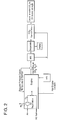
- this invention relates to the integration of the various components for efficient oxy-combustion in the ICE of a mobile source as has been described above, followed by CO 2 capture from the exhaust and temporary onboard storage using waste heat from the engine, mobile source, the engine's exhaust stream and the liquid coolant system. It includes the steps of:(a) O 2 separation using one or more component(s) or unit(s), (b) converting some of the waste heat into power (work energy), and (c) using this power to increase the density of captured CO 2 for temporary on-board storage and to power the O 2 separation unit. All or part of the energy requirements for these steps come from the engine waste heat (see example 1).
- the waste heat produced by a typical engine consists mainly of hot exhaust gases ( ⁇ 600-650 °C) and hot coolant ( ⁇ 100-120 °C) as shown in Figure 1 .
- This heat energy totals about 60% of the energy that typical hydrocarbon (HC) fuels provide.
- Energy is needed to separate oxygen from and compress/liquefy or freeze all or part of the produced CO 2 for efficient onboard storage. This energy has to be a mix of work and heat energies.
- the work component of the energy is generated using part of the waste heat to produce this work.
- Some waste heat could be used to power an on-board O 2 separation unit. Part of the exhaust gases can be recycled to control the temperature of the engine.
- part of the engine power, or the electricity stored in onboard batteries could be used.
- part of the energy required for capture and densification will come from the waste heat.
- the CO 2 densification component can be a single or multiple stage compression with the required active/passive cooling system to ensure pressurization, liquification or solidification of CO 2 before storage temporarily onboard.
- the CO 2 storage could be in the form of single or multiple tanks onboard the mobile sources.
- the fuel tank could also be used to store the captured CO 2 by having a moving partition between the fuel side and the CO 2 side. All components could be integrated with the mobile source control system or a separate control system to optimize performance.
- the engine block 20 includes an intake manifold 22 the flow of air being controlled by intake valve 24 and an exhaust manifold 26 closed by exhaust valve 28.
- Cylinder 30 contains piston 32 which is fitted with one or more piston rings 34.
- the intake down stroke commences with the closing of the exhaust valve 28 and the opening of the intake valve 24 that is coordinated with the down stroke of piston 32 which draws the mixture of air and fuel into the open portion of cylinder 30 from the intake manifold 22.
- both valves 24 and 28 are closed and the fuel/air mixture is compressed as the piston 32 moves to the top of the cylinder, the spark plug or other ignition device 36 ignites the fuel/air mixture and a controlled combustion occurs which drives the piston to the bottom of the cylinder 30 in the power down stroke, causing the crankshaft 38 to turn and provide the propelling force to the vehicle through a transmission and drive train (not shown).
- exhaust valve 28 is opened and the hot exhaust gases exit through exhaust manifold 26, and the cycle is repeated with the closing of the exhaust valve 28 and opening of the intake valve 24.
- an air separation membrane 50 is positioned in the intake air manifold 22 to pass oxygen into the cylinder during the air intake down stroke. Nitrogen present in the intake air stream is maintained on the upstream side of the membrane 50 as the retentate gas and is discharged from the manifold into the atmosphere. Since no nitrogen is exposed to the high temperature and pressure oxidation conditions during combustion, no NO x compounds are produced and emitted with the exhaust gas.
- the air intake manifold includes an orifice downstream of the membrane that is sized and configured to maintain a back pressure, while at the same time permitting the nitrogen-enriched retentate stream to be released into the atmosphere. This arrangement is illustrated schematically in Fig.
- a plurality of fuel injection ports or nozzles can be utilized to more evenly distribute the fuel in the air intake manifold 22 and assure a more uniform mixture in response to changes in load, sudden acceleration or deceleration, and other changes in the operating conditions of the ICE.
- V-blocks which can contain from four, six, eight or even ten cylinders.
- the configuration of the air intake manifold corresponding to element 22 in the figures is more complex than the essentially straight air intake manifold used with an I-block engine, the general principles of operation of the air separation membranes described above apply.
- the air intake manifold of each cylinder can be provided with a retentate orifice downstream of the membrane 50 (not shown).
- the fuel is added to the oxygen downstream of the membrane 50 and an opportunity must be provided for adequate mixing of the fuel/oxygen-enriched air mixture must be provided.
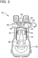
- an air separation membrane 150 is incorporated into the inlet valve 124.
- Fuel is introduced directly into the cylinder 130 via direct fuel injection system 160, which is also known as gasoline direct injection or GDI.
- direct fuel injection system 160 which is also known as gasoline direct injection or GDI.
- the fuel is highly pressurized and is introduced directly into the cylinder during the down stroke and it is mixed with the oxygen or air-enriched oxygen that has passed through the air separation membrane 150.
- the direct fuel injection, or GDI system enables a stratified fuel charge combustion, or ultra-lean burn, to improve fuel efficiency and reduce emission levels under low ICE loads.
- the valve assembly 124 containing the membrane 150 remains closed during the intake down stroke.
- a fuel-tight cover 152 mounted on valve stem 125 is lowered to prevent loss of the fuel and air mixture and the pressure of the down stroke through the membrane.
- this arrangement will require some modification of the valve stem and the associated operating mechanism.
- a further advantage of the adaptation of the invention to this embodiment is that fewer modifications are required to the structure and mode of operation of a direct fuel injection system.
- valve assembly 124 containing the air separation membrane 150 remains closed for all or a portion of the intake down stroke and is open for a portion in order to admit a volume of atmospheric air that is required to support combustion.
- the cylinder head is provided with at least one additional air intake manifold port and intake valve that admits atmospheric oxygen directly and a second port that admits oxygen that has passed through the air separation membrane 150 as described above in connection with Fig. 5 or through a membrane 50 as previously described in connection with Fig. 3
- air separation membranes 250 that pass oxygen are integrated into the wall of all or a selected number of the cylinders 230 in a modified ICE 210.
- air separation membranes 250 are positioned in the cylinder walls 230 and are supplied with atmospheric air passing through manifolds, or atmospheric air delivery channels 222.
- the air delivery channels can surround the periphery of the cylinder in order to increase the surface area of membranes serving each cylinder.
- a sufficient number of membranes 250 are provided to meet the oxygen requirements for complete combustion of the fuel in the cylinder under the range of operating specifications of the ICE.
- the intake valve assembly and air intake manifold inlet to the cylinder are eliminated, thus simplifying the construction of the engine.
- the retentate nitrogen and any other atmospheric gases are released to the atmosphere via one or more orifices which allow for the flow of fresh atmospheric air to the membranes.
- a membrane cover can be provided to isolate the oxygen-passing membranes from the compressed gases in the cylinder.
- the engine block and cylinder walls are modified to provide for the installation of the membranes 250 and to provide communicating internal manifolds or air channels 222 for the introduction of pressurized atmospheric air.
- a membrane material is utilized that restricts or impedes the flow of nitrogen, NO x and CO 2 .
- the current is interrupted to discontinue the ion transport through the electrolyte.
- an additional valve is provided in the cylinder head to admit atmospheric air in order to meet oxygen requirements associated with rapid acceleration, increased loads and the like.
- atmospheric air is admitted to the cylinder to support the complete combustion of the fuel, some NO x compounds will be produced and emitted in the exhaust gases.
- the same valve, or an additional valve in the cylinder head can be utilized to recirculate hot exhaust gases in order to control the combustion temperature and therefore the heat transferred to the engine block and its associated components.
- the O 2 separation unit or membrane can be adapted for use in different types of internal combustion engines and propulsion systems.
- the invention can be used with 4-stroke, 2-stroke, 6-stroke, Wankle, Atkinson, Stirling, gnome, gas turbine, jet, wave disc, and other types driven by the combustion of any type of hydrocarbon fuel.
Landscapes
- Engineering & Computer Science (AREA)
- Chemical & Material Sciences (AREA)
- Combustion & Propulsion (AREA)
- Mechanical Engineering (AREA)
- General Engineering & Computer Science (AREA)
- Analytical Chemistry (AREA)
- Organic Chemistry (AREA)
- Chemical Kinetics & Catalysis (AREA)
- Oil, Petroleum & Natural Gas (AREA)
- General Chemical & Material Sciences (AREA)
- Inorganic Chemistry (AREA)
- Separation Using Semi-Permeable Membranes (AREA)
- Exhaust-Gas Circulating Devices (AREA)
Applications Claiming Priority (2)
| Application Number | Priority Date | Filing Date | Title |
|---|---|---|---|
| US201261614062P | 2012-03-22 | 2012-03-22 | |
| PCT/US2013/032913 WO2013142469A1 (en) | 2012-03-22 | 2013-03-19 | Apparatus and method for oxy-combustion of fuels in internal combustion engines |
Publications (2)
| Publication Number | Publication Date |
|---|---|
| EP2828502A1 EP2828502A1 (en) | 2015-01-28 |
| EP2828502B1 true EP2828502B1 (en) | 2017-08-16 |
Family
ID=48050309
Family Applications (1)
| Application Number | Title | Priority Date | Filing Date |
|---|---|---|---|
| EP13714803.7A Not-in-force EP2828502B1 (en) | 2012-03-22 | 2013-03-19 | Apparatus and method for oxy-combustion of fuels in internal combustion engines |
Country Status (8)
| Country | Link |
|---|---|
| US (2) | US9488100B2 (enExample) |
| EP (1) | EP2828502B1 (enExample) |
| JP (1) | JP6325516B2 (enExample) |
| KR (3) | KR102087881B1 (enExample) |
| CN (1) | CN104411946B (enExample) |
| CA (1) | CA2866409A1 (enExample) |
| SG (1) | SG11201405432SA (enExample) |
| WO (1) | WO2013142469A1 (enExample) |
Cited By (1)
| Publication number | Priority date | Publication date | Assignee | Title |
|---|---|---|---|---|
| IT202100000794A1 (it) | 2021-01-18 | 2022-07-18 | Silvano Tosti | Processo di combustione con aria trattata mediante sistemi a membrana e relativo apparato |
Families Citing this family (31)
| Publication number | Priority date | Publication date | Assignee | Title |
|---|---|---|---|---|
| CN103696887A (zh) * | 2013-12-20 | 2014-04-02 | 华南理工大学 | 一种内燃机减氮增氧进气装置及其控制方法 |
| US9702300B2 (en) | 2014-02-12 | 2017-07-11 | King Fahd University Of Petroleum And Minerals | Applications of oxy-fuel combustion technology into gas turbine combustors and ion transport membrane reactors |
| US20150260131A1 (en) * | 2014-03-17 | 2015-09-17 | Woodward, Inc. | Supplying Oxygen to an Engine |
| US8925518B1 (en) | 2014-03-17 | 2015-01-06 | Woodward, Inc. | Use of prechambers with dual fuel source engines |
| CN106286022A (zh) * | 2015-05-14 | 2017-01-04 | 江波 | 富氧空气分离膜在内燃机上的应用 |
| US9598993B2 (en) * | 2015-06-19 | 2017-03-21 | Saudi Arabian Oil Company | Integrated process for CO2 capture and use in thermal power production cycle |
| CN105604667A (zh) * | 2015-12-31 | 2016-05-25 | 北京建筑大学 | 一种柴油机co2捕捉系统及其工作方法 |
| CN106321232A (zh) * | 2016-09-22 | 2017-01-11 | 唐松立 | 纯氧醇类内燃双能发动机系统 |
| DE102017000071A1 (de) * | 2017-01-05 | 2018-07-05 | CCP Technology GmbH | Verbrennungsmotor mit verringertem NOx-Ausstoß |
| GB2554479B (en) * | 2017-02-27 | 2019-02-27 | Rocco Tulino Rosario | Electro-physical apparatus for the activation of nitrogen contained in engines at internal combustion emissions |
| US10458373B2 (en) * | 2017-12-20 | 2019-10-29 | Tenneco Automotive Operating Company Inc. | System including oxygen separation device |
| US10408139B1 (en) * | 2018-03-29 | 2019-09-10 | Saudi Arabian Oil Company | Solvent-based adsorbent regeneration for onboard octane on-demand and cetane on-demand |
| JP6996432B2 (ja) * | 2018-06-20 | 2022-02-04 | トヨタ自動車株式会社 | 内燃機関を動力として用いる車両に搭載するためのco2分離システム |
| IT201800007572A1 (it) * | 2018-07-27 | 2020-01-27 | Eni Spa | Kit per un motore a combustione interna. |
| FR3087670B1 (fr) * | 2018-10-26 | 2020-10-23 | Air Liquide | Procede de conditionnement d'un recipient comprenant un materiau granulaire |
| US12194405B2 (en) * | 2018-12-21 | 2025-01-14 | Prodose | Method and device for reducing the increase in temperature at the surface of the terrestrial globe, vehicle and station for implementing said method |
| ES2751129B2 (es) * | 2019-03-28 | 2021-03-29 | Univ Valencia Politecnica | Motor de combustion interna y metodo de funcionamiento del mismo |
| WO2020223391A1 (en) | 2019-04-29 | 2020-11-05 | Nextwatts, Inc. | Building emission processing and/or sequestration systems and methods |
| DE102019128882B3 (de) | 2019-10-25 | 2020-12-17 | Fraunhofer-Gesellschaft zur Förderung der angewandten Forschung e.V. | Verfahren zur prozessintegrierten Sauerstoff-Versorgung eines Wasserstoff-Kreislaufmotors mit Kreislaufführung eines Edelgases |
| US11512656B2 (en) * | 2020-10-15 | 2022-11-29 | Saudi Arabian Oil Company | Oxycombustion engine systems including recirculation management features |
| JP2024514378A (ja) * | 2021-03-31 | 2024-04-02 | カーボンクエスト, インコーポレイテッド | Co2分離システムおよび方法 |
| US12416285B2 (en) | 2021-04-27 | 2025-09-16 | Zero Nox, Inc. | Venturi device with forced induction systems and methods |
| JP2025500022A (ja) | 2021-11-23 | 2025-01-07 | ゼロ ノックス, インコーポレイテッド | 強制インダクションシステム付きベンチュリ装置および方法 |
| CN114768465B (zh) * | 2022-03-31 | 2023-11-28 | 上海交通大学 | 一种多级复叠连续固体吸附碳捕集系统及运行方法 |
| CN114572424A (zh) * | 2022-04-21 | 2022-06-03 | 广州大学 | 一种近地卫星吸气式电推进器及其速度控制方法 |
| EP4609071A1 (en) | 2022-10-26 | 2025-09-03 | H2Diesel, Inc. | Method and devices combining diesel fuel and hydrogen gas to form a homogenized liquid hydro-diesel fuel |
| US12040513B2 (en) | 2022-11-18 | 2024-07-16 | Carbon Ventures, Llc | Enhancing efficiencies of oxy-combustion power cycles |
| WO2024137110A1 (en) * | 2022-12-21 | 2024-06-27 | H2Diesel, Inc. | System and method for using concentrated oxygen for gas intake into an internal combustion engine |
| US12134990B2 (en) | 2023-03-13 | 2024-11-05 | H2Diesel, Inc. | System for remotely monitoring and controlling operation of a hydro-diesel engine |
| WO2025037030A1 (de) * | 2023-08-17 | 2025-02-20 | Eriver Ag | System und verfahren zur speicherung von verbrennungsabgasen eines verbrennungssystems |
| US12370505B2 (en) | 2023-10-06 | 2025-07-29 | H2Diesel, Inc. | Hydro-diesel engine system having separate agitation mixing and chemical mixing of hydrogen gas into liquid diesel fuel |
Citations (4)
| Publication number | Priority date | Publication date | Assignee | Title |
|---|---|---|---|---|
| DE4201423A1 (de) * | 1992-01-21 | 1993-07-22 | Kloeckner Humboldt Deutz Ag | Vorrichtung zur verminderung der partikelemission von dieselbrennkraftmaschinen |
| US5636619A (en) * | 1993-02-18 | 1997-06-10 | The University Of Chicago | Method and apparatus for reducing cold-phase emissions by utilizing oxygen-enriched intake air |
| WO1999067508A1 (en) * | 1998-06-22 | 1999-12-29 | The University Of Chicago | Method and apparatus for reducing particulates and nox emissions from diesel engines utilizing oxygen enriched combustion air |
| GB2342390A (en) * | 1998-10-02 | 2000-04-12 | Finch International Ltd | Providing an oxygen-rich atmosphere in the combustion chamber of a gas-fuelled compression-ignition engine |
Family Cites Families (70)
| Publication number | Priority date | Publication date | Assignee | Title |
|---|---|---|---|---|
| JPS5545737B2 (enExample) * | 1971-11-25 | 1980-11-19 | ||
| JPS4864320A (enExample) | 1971-12-10 | 1973-09-06 | ||
| DE3663622D1 (en) * | 1985-03-01 | 1989-07-06 | Air Prod & Chem | Method for gas separation |
| US4781907A (en) | 1985-12-04 | 1988-11-01 | Mcneill John M | Production of membrane-derived nitrogen from combustion gases |
| US5021137A (en) | 1986-07-25 | 1991-06-04 | Ceramatec, Inc. | Ceramic solid electrolyte based electrochemical oxygen concentrator cell |
| US5051113A (en) | 1990-06-13 | 1991-09-24 | Du Pont Canada Inc. | Air-intake system for mobile engines |
| US5441610A (en) * | 1992-02-28 | 1995-08-15 | Renlund; Gary M. | Oxygen supply and removal method and apparatus |
| US5302258A (en) * | 1992-02-28 | 1994-04-12 | Triox Technologies, Inc. | Method and apparatus for separating oxygen from a gaseous mixture |
| US5516359A (en) * | 1993-12-17 | 1996-05-14 | Air Products And Chemicals, Inc. | Integrated high temperature method for oxygen production |
| DE4404681C1 (de) | 1994-02-15 | 1995-05-04 | Bosch Gmbh Robert | Vorrichtung und Verfahren zur Reduzierung von Schadstoffen in Verbrennungsabgasen |
| CZ76397A3 (cs) * | 1994-09-12 | 1998-08-12 | Entherm, Inc. | Motor se vstřikováním vody do válce |
| US6170264B1 (en) | 1997-09-22 | 2001-01-09 | Clean Energy Systems, Inc. | Hydrocarbon combustion power generation system with CO2 sequestration |
| US5680764A (en) | 1995-06-07 | 1997-10-28 | Clean Energy Systems, Inc. | Clean air engines transportation and other power applications |
| DE19710839A1 (de) | 1997-03-15 | 1998-09-17 | Bosch Gmbh Robert | Verfahren zur Reduzierung von Schadstoffen in Verbrennungsabgasen von Verbrennungsmotoren |
| JP3817912B2 (ja) * | 1998-01-27 | 2006-09-06 | 日産自動車株式会社 | 微生物の反応浄化装置を備えるエンジンシステム |
| US5960777A (en) * | 1998-02-20 | 1999-10-05 | Compact Membrane Systems, Inc. | Combustion engine air supply system |
| US6173567B1 (en) * | 1998-09-14 | 2001-01-16 | The University Of Chicago | Method to reduce diesel engine exhaust emissions |
| IL126708A0 (en) * | 1998-10-22 | 1999-08-17 | Lerner Moshe | A device for supereffective combustion of fuel |
| GB9826463D0 (en) | 1998-12-03 | 1999-01-27 | Rover Group | An exhaust arrangemnt |
| US6609582B1 (en) * | 1999-04-19 | 2003-08-26 | Delphi Technologies, Inc. | Power generation system and method |
| GB2349175A (en) | 1999-04-21 | 2000-10-25 | Finch International Ltd | Combustion of pyrolysis oil and oxygen-enriched air in compression-ignition engines |
| JP5122038B2 (ja) * | 1999-06-18 | 2013-01-16 | 坂東機工株式会社 | ガラス板の加工装置 |
| US6352068B1 (en) * | 1999-12-27 | 2002-03-05 | Honda Giken Kogyo Kabushiki Kaisha | Method and apparatus for reducing oxides of nitrogen in the exhaust gas of an internal combustion engine |
| GB2358434B (en) | 2000-01-21 | 2004-01-14 | Finch Internat Ltd | Disposal of waste mineral oils by means of combustion |
| DE10003525A1 (de) * | 2000-01-27 | 2001-08-02 | Mann & Hummel Filter | Ansaugsystem für eine Brennkraftmaschine mit einer vornehmlich für Sauerstoffmoleküle durchlässigen Membran |
| US6293084B1 (en) * | 2000-05-04 | 2001-09-25 | Praxair Technology, Inc. | Oxygen separator designed to be integrated with a gas turbine and method of separating oxygen |
| US6382958B1 (en) | 2000-07-12 | 2002-05-07 | Praxair Technology, Inc. | Air separation method and system for producing oxygen to support combustion in a heat consuming device |
| US20020100836A1 (en) * | 2001-01-31 | 2002-08-01 | Hunt Robert Daniel | Hydrogen and oxygen battery, or hudrogen and oxygen to fire a combustion engine and/or for commerce. |
| DE10118315C2 (de) * | 2001-04-11 | 2003-02-20 | Mtu Friedrichshafen Gmbh | Brennkraftmaschine |
| US6619041B2 (en) * | 2001-06-29 | 2003-09-16 | L'air Liquide - Societe Anonyme A Directoire Et Conseil De Surveillance Pour L'etude Et L'exploitation Des Procedes Georges Claude | Steam generation apparatus and methods |
| DE10142946B4 (de) | 2001-09-01 | 2005-06-16 | DRäGER AEROSPACE GMBH | Vorrichtung zur Anreicherung von Luft mit Sauerstoff |
| US6722352B2 (en) * | 2001-11-06 | 2004-04-20 | Praxair Technology, Inc. | Pressure-swing adsorption system for internal combustion engines |
| EP1481703A4 (en) * | 2002-03-05 | 2011-02-02 | Teijin Ltd | OXYGEN ENRICHISER |
| US6681752B1 (en) * | 2002-08-05 | 2004-01-27 | Dynojet Research Company | Fuel injection system method and apparatus using oxygen sensor signal conditioning to modify air/fuel ratio |
| CA2505354C (en) * | 2002-11-08 | 2012-04-03 | Alstom Technology Ltd. | Gas turbine power plant and method of operating the same |
| US6945029B2 (en) * | 2002-11-15 | 2005-09-20 | Clean Energy Systems, Inc. | Low pollution power generation system with ion transfer membrane air separation |
| DE10325413B4 (de) * | 2003-06-05 | 2015-03-05 | Audi Ag | Verfahren zum Betreiben einer Brennkraftmaschine eines Fahrzeuges, insbesondere eines Kraftfahtzeuges sowie Vorrichtung zur Durchführung eines derartigen Verfahrens |
| US7658788B2 (en) * | 2003-08-06 | 2010-02-09 | Air Products And Chemicals, Inc. | Ion transport membrane module and vessel system with directed internal gas flow |
| US7128064B2 (en) | 2004-02-20 | 2006-10-31 | Heider James E | Method and apparatus to provide oxygen enriched air to the intake manifold of an internal combustion engine |
| DE102004020450A1 (de) | 2004-04-27 | 2005-11-24 | Nouhad Bachnak | Verbrennungsmotor/Turbinentriebwerk |
| DE102004041263A1 (de) * | 2004-08-26 | 2006-03-02 | Daimlerchrysler Ag | Brennkraftmaschine mit einer Lufttrenneinheit und Verfahren zum Betreiben einer solchen Brennkraftmaschine |
| DE202004015797U1 (de) | 2004-10-12 | 2004-12-16 | Lin, Yung-Sheng, I-Lian | Motorzylinder mit einer Innenschicht aus Gold- und Titannanopartikeln |
| JP2006138225A (ja) | 2004-11-10 | 2006-06-01 | Denso Corp | 吸気装置 |
| KR100919357B1 (ko) | 2005-03-01 | 2009-09-25 | 사우디 아라비안 오일 컴퍼니 | 차량에서의 탄화수소 연료의 탑재형 탈탄화 방법 |
| DE102005016125A1 (de) * | 2005-04-08 | 2006-10-12 | Robert Bosch Gmbh | Zündsystem einer Brennkraftmaschine |
| JP4192930B2 (ja) * | 2005-09-12 | 2008-12-10 | トヨタ自動車株式会社 | 内燃機関 |
| GB0519402D0 (en) * | 2005-09-23 | 2005-11-02 | Tonery David | Air intake system |
| US7650744B2 (en) * | 2006-03-24 | 2010-01-26 | General Electric Company | Systems and methods of reducing NOx emissions in gas turbine systems and internal combustion engines |
| US7464540B2 (en) * | 2006-05-31 | 2008-12-16 | Caterpillar Inc. | Ammonia producing engine utilizing oxygen separation |
| AT503126B1 (de) * | 2006-06-28 | 2007-08-15 | Figl Gerhard | Verbrennungskraftmaschine |
| JP4721967B2 (ja) * | 2006-07-06 | 2011-07-13 | 吸着技術工業株式会社 | 高温酸素吸着剤を利用した圧力スイング法による酸素製造方法及び装置 |
| US20080169449A1 (en) * | 2006-09-08 | 2008-07-17 | Eltron Research Inc. | Catalytic membrane reactor and method for production of synthesis gas |
| US7927568B2 (en) * | 2006-10-26 | 2011-04-19 | Foster Wheeler Energy Corporation | Method of and apparatus for CO2 capture in oxy-combustion |
| US8607769B2 (en) * | 2006-11-16 | 2013-12-17 | Siddhartha Gaur | Combustion controlled NOx reduction method and device |
| DE102007006444B4 (de) * | 2007-02-05 | 2015-05-13 | Airbus Defence and Space GmbH | Mikrotriebwerk, insbesondere zur Verwendung als Lageregelungstriebwerk, Kleintriebwerk sowie Verfahren zum Herstellen eines Mikrotriebwerks |
| CN201031677Y (zh) * | 2007-03-30 | 2008-03-05 | 辽河石油勘探局 | 锅炉烟道气加压吸收二氧化碳液化注井采油装置 |
| JP2009008053A (ja) * | 2007-06-29 | 2009-01-15 | Mitsubishi Motors Corp | 内燃機関の排気浄化装置 |
| US20090071434A1 (en) * | 2007-09-19 | 2009-03-19 | Macmillan Shaun T | Low heat rejection high efficiency internal combustion engine |
| DE102007056841A1 (de) * | 2007-11-23 | 2009-05-28 | Forschungszentrum Jülich GmbH | Membran-Kraftwerk und Verfahren zum Betreiben eines solchen |
| US20090139497A1 (en) * | 2007-11-30 | 2009-06-04 | Bo Shi | Engine having thin film oxygen separation system |
| EP2227624B1 (en) * | 2007-12-06 | 2020-04-29 | Sustainable Energy Solutions, LLC | Methods and systems for generating power from a turbine using pressurized nitrogen |
| US8550058B2 (en) * | 2007-12-21 | 2013-10-08 | Ford Global Technologies, Llc | Fuel rail assembly including fuel separation membrane |
| ES2733083T3 (es) * | 2009-02-26 | 2019-11-27 | 8 Rivers Capital Llc | Aparato y método para quemar un combustible a alta presión y alta temperatura, y sistema y dispositivo asociados |
| US8596075B2 (en) * | 2009-02-26 | 2013-12-03 | Palmer Labs, Llc | System and method for high efficiency power generation using a carbon dioxide circulating working fluid |
| JP2010216303A (ja) * | 2009-03-13 | 2010-09-30 | Denso Corp | 内燃機関の窒素富化ガス供給装置 |
| FR2952406A3 (fr) | 2009-11-10 | 2011-05-13 | Renault Sa | Groupe motopropulseur de vehicule automobile a emissions polluantes reduites. |
| US7891186B1 (en) * | 2010-01-12 | 2011-02-22 | Primlani Indru J | System and method of waste heat recovery and utilization |
| JP5545737B2 (ja) * | 2010-08-03 | 2014-07-09 | 富士機械製造株式会社 | 部品実装機及び画像処理方法 |
| KR20130029819A (ko) * | 2010-08-24 | 2013-03-25 | 아사히 가세이 케미칼즈 가부시키가이샤 | 내연 기관의 질소 산화물의 삭감 방법 및 그 장치 |
| JP5315308B2 (ja) | 2010-08-25 | 2013-10-16 | トヨタ自動車株式会社 | 内燃機関とその製造方法 |
-
2013
- 2013-03-14 US US13/804,291 patent/US9488100B2/en active Active
- 2013-03-19 SG SG11201405432SA patent/SG11201405432SA/en unknown
- 2013-03-19 KR KR1020197009758A patent/KR102087881B1/ko not_active Expired - Fee Related
- 2013-03-19 WO PCT/US2013/032913 patent/WO2013142469A1/en not_active Ceased
- 2013-03-19 JP JP2015501843A patent/JP6325516B2/ja active Active
- 2013-03-19 KR KR1020187030280A patent/KR102032534B1/ko active Active
- 2013-03-19 CN CN201380014508.0A patent/CN104411946B/zh not_active Expired - Fee Related
- 2013-03-19 EP EP13714803.7A patent/EP2828502B1/en not_active Not-in-force
- 2013-03-19 KR KR1020147029673A patent/KR101911990B1/ko active Active
- 2013-03-19 CA CA2866409A patent/CA2866409A1/en not_active Abandoned
-
2016
- 2016-11-04 US US15/343,626 patent/US10280877B2/en active Active
Patent Citations (4)
| Publication number | Priority date | Publication date | Assignee | Title |
|---|---|---|---|---|
| DE4201423A1 (de) * | 1992-01-21 | 1993-07-22 | Kloeckner Humboldt Deutz Ag | Vorrichtung zur verminderung der partikelemission von dieselbrennkraftmaschinen |
| US5636619A (en) * | 1993-02-18 | 1997-06-10 | The University Of Chicago | Method and apparatus for reducing cold-phase emissions by utilizing oxygen-enriched intake air |
| WO1999067508A1 (en) * | 1998-06-22 | 1999-12-29 | The University Of Chicago | Method and apparatus for reducing particulates and nox emissions from diesel engines utilizing oxygen enriched combustion air |
| GB2342390A (en) * | 1998-10-02 | 2000-04-12 | Finch International Ltd | Providing an oxygen-rich atmosphere in the combustion chamber of a gas-fuelled compression-ignition engine |
Cited By (1)
| Publication number | Priority date | Publication date | Assignee | Title |
|---|---|---|---|---|
| IT202100000794A1 (it) | 2021-01-18 | 2022-07-18 | Silvano Tosti | Processo di combustione con aria trattata mediante sistemi a membrana e relativo apparato |
Also Published As
| Publication number | Publication date |
|---|---|
| CN104411946B (zh) | 2017-12-15 |
| KR20190039358A (ko) | 2019-04-10 |
| KR101911990B1 (ko) | 2018-10-25 |
| EP2828502A1 (en) | 2015-01-28 |
| US10280877B2 (en) | 2019-05-07 |
| US20170074213A1 (en) | 2017-03-16 |
| WO2013142469A1 (en) | 2013-09-26 |
| JP2015510991A (ja) | 2015-04-13 |
| CA2866409A1 (en) | 2013-09-26 |
| SG11201405432SA (en) | 2014-10-30 |
| US20130247886A1 (en) | 2013-09-26 |
| KR102087881B1 (ko) | 2020-05-15 |
| US9488100B2 (en) | 2016-11-08 |
| CN104411946A (zh) | 2015-03-11 |
| JP6325516B2 (ja) | 2018-05-16 |
| KR20140143200A (ko) | 2014-12-15 |
| KR102032534B1 (ko) | 2019-10-16 |
| KR20180119167A (ko) | 2018-11-01 |
Similar Documents
| Publication | Publication Date | Title |
|---|---|---|
| US10280877B2 (en) | Apparatus and method for oxy-combustion of fuels in internal combustion engines | |
| US6742507B2 (en) | Feed composition modification for internal combustion engines | |
| US7041272B2 (en) | Systems and processes for providing hydrogen to fuel cells | |
| AU2003295610B2 (en) | Low pollution power generation system with ion transfer membrane air separation | |
| EP2673071B1 (en) | Membrane separation methods and system utilizing waste heat for on-board recovery and storage of co2 from motor vehicle internal combustion engine exhaust gases | |
| US20020002827A1 (en) | Clean air engines for transportation and other power applications | |
| EP3951159B1 (en) | Internal combustion engine and operating method of same | |
| US20220325684A1 (en) | Air separator-enhanced combustion systems | |
| WO2002042628A2 (en) | Feed composition modification for internal combustion engines | |
| Rigby et al. | Application of membrane gas separation to oxygen enrichment of diesel engines | |
| JP2004237976A (ja) | 車両 | |
| CA2324702A1 (en) | Reformate purification and heat recovery for fuel cell | |
| WO2020021486A1 (en) | Kit for an internal combustion engine | |
| CA2424615A1 (en) | Systems and processes for providing hydrogen to fuel cells | |
| JPH01187358A (ja) | 内燃機関システム |
Legal Events
| Date | Code | Title | Description |
|---|---|---|---|
| PUAI | Public reference made under article 153(3) epc to a published international application that has entered the european phase |
Free format text: ORIGINAL CODE: 0009012 |
|
| 17P | Request for examination filed |
Effective date: 20141021 |
|
| AK | Designated contracting states |
Kind code of ref document: A1 Designated state(s): AL AT BE BG CH CY CZ DE DK EE ES FI FR GB GR HR HU IE IS IT LI LT LU LV MC MK MT NL NO PL PT RO RS SE SI SK SM TR |
|
| AX | Request for extension of the european patent |
Extension state: BA ME |
|
| DAX | Request for extension of the european patent (deleted) | ||
| 17Q | First examination report despatched |
Effective date: 20160126 |
|
| GRAP | Despatch of communication of intention to grant a patent |
Free format text: ORIGINAL CODE: EPIDOSNIGR1 |
|
| RIC1 | Information provided on ipc code assigned before grant |
Ipc: F02M 25/00 20060101ALI20170203BHEP Ipc: B01D 53/22 20060101ALI20170203BHEP Ipc: F02B 77/02 20060101ALI20170203BHEP Ipc: F02B 47/10 20060101AFI20170203BHEP Ipc: F02B 21/00 20060101ALI20170203BHEP Ipc: C01B 13/02 20060101ALI20170203BHEP Ipc: F02M 25/12 20060101ALI20170203BHEP |
|
| INTG | Intention to grant announced |
Effective date: 20170224 |
|
| GRAS | Grant fee paid |
Free format text: ORIGINAL CODE: EPIDOSNIGR3 |
|
| GRAA | (expected) grant |
Free format text: ORIGINAL CODE: 0009210 |
|
| AK | Designated contracting states |
Kind code of ref document: B1 Designated state(s): AL AT BE BG CH CY CZ DE DK EE ES FI FR GB GR HR HU IE IS IT LI LT LU LV MC MK MT NL NO PL PT RO RS SE SI SK SM TR |
|
| REG | Reference to a national code |
Ref country code: GB Ref legal event code: FG4D |
|
| REG | Reference to a national code |
Ref country code: CH Ref legal event code: EP |
|
| REG | Reference to a national code |
Ref country code: IE Ref legal event code: FG4D |
|
| REG | Reference to a national code |
Ref country code: AT Ref legal event code: REF Ref document number: 919293 Country of ref document: AT Kind code of ref document: T Effective date: 20170915 |
|
| REG | Reference to a national code |
Ref country code: DE Ref legal event code: R096 Ref document number: 602013025079 Country of ref document: DE |
|
| REG | Reference to a national code |
Ref country code: NL Ref legal event code: FP |
|
| REG | Reference to a national code |
Ref country code: LT Ref legal event code: MG4D |
|
| REG | Reference to a national code |
Ref country code: AT Ref legal event code: MK05 Ref document number: 919293 Country of ref document: AT Kind code of ref document: T Effective date: 20170816 |
|
| PG25 | Lapsed in a contracting state [announced via postgrant information from national office to epo] |
Ref country code: LT Free format text: LAPSE BECAUSE OF FAILURE TO SUBMIT A TRANSLATION OF THE DESCRIPTION OR TO PAY THE FEE WITHIN THE PRESCRIBED TIME-LIMIT Effective date: 20170816 Ref country code: AT Free format text: LAPSE BECAUSE OF FAILURE TO SUBMIT A TRANSLATION OF THE DESCRIPTION OR TO PAY THE FEE WITHIN THE PRESCRIBED TIME-LIMIT Effective date: 20170816 Ref country code: SE Free format text: LAPSE BECAUSE OF FAILURE TO SUBMIT A TRANSLATION OF THE DESCRIPTION OR TO PAY THE FEE WITHIN THE PRESCRIBED TIME-LIMIT Effective date: 20170816 Ref country code: NO Free format text: LAPSE BECAUSE OF FAILURE TO SUBMIT A TRANSLATION OF THE DESCRIPTION OR TO PAY THE FEE WITHIN THE PRESCRIBED TIME-LIMIT Effective date: 20171116 Ref country code: FI Free format text: LAPSE BECAUSE OF FAILURE TO SUBMIT A TRANSLATION OF THE DESCRIPTION OR TO PAY THE FEE WITHIN THE PRESCRIBED TIME-LIMIT Effective date: 20170816 |
|
| PG25 | Lapsed in a contracting state [announced via postgrant information from national office to epo] |
Ref country code: RS Free format text: LAPSE BECAUSE OF FAILURE TO SUBMIT A TRANSLATION OF THE DESCRIPTION OR TO PAY THE FEE WITHIN THE PRESCRIBED TIME-LIMIT Effective date: 20170816 Ref country code: IS Free format text: LAPSE BECAUSE OF FAILURE TO SUBMIT A TRANSLATION OF THE DESCRIPTION OR TO PAY THE FEE WITHIN THE PRESCRIBED TIME-LIMIT Effective date: 20171216 Ref country code: PL Free format text: LAPSE BECAUSE OF FAILURE TO SUBMIT A TRANSLATION OF THE DESCRIPTION OR TO PAY THE FEE WITHIN THE PRESCRIBED TIME-LIMIT Effective date: 20170816 Ref country code: GR Free format text: LAPSE BECAUSE OF FAILURE TO SUBMIT A TRANSLATION OF THE DESCRIPTION OR TO PAY THE FEE WITHIN THE PRESCRIBED TIME-LIMIT Effective date: 20171117 Ref country code: LV Free format text: LAPSE BECAUSE OF FAILURE TO SUBMIT A TRANSLATION OF THE DESCRIPTION OR TO PAY THE FEE WITHIN THE PRESCRIBED TIME-LIMIT Effective date: 20170816 Ref country code: BG Free format text: LAPSE BECAUSE OF FAILURE TO SUBMIT A TRANSLATION OF THE DESCRIPTION OR TO PAY THE FEE WITHIN THE PRESCRIBED TIME-LIMIT Effective date: 20171116 Ref country code: ES Free format text: LAPSE BECAUSE OF FAILURE TO SUBMIT A TRANSLATION OF THE DESCRIPTION OR TO PAY THE FEE WITHIN THE PRESCRIBED TIME-LIMIT Effective date: 20170816 |
|
| REG | Reference to a national code |
Ref country code: FR Ref legal event code: PLFP Year of fee payment: 6 |
|
| PG25 | Lapsed in a contracting state [announced via postgrant information from national office to epo] |
Ref country code: CZ Free format text: LAPSE BECAUSE OF FAILURE TO SUBMIT A TRANSLATION OF THE DESCRIPTION OR TO PAY THE FEE WITHIN THE PRESCRIBED TIME-LIMIT Effective date: 20170816 Ref country code: RO Free format text: LAPSE BECAUSE OF FAILURE TO SUBMIT A TRANSLATION OF THE DESCRIPTION OR TO PAY THE FEE WITHIN THE PRESCRIBED TIME-LIMIT Effective date: 20170816 Ref country code: DK Free format text: LAPSE BECAUSE OF FAILURE TO SUBMIT A TRANSLATION OF THE DESCRIPTION OR TO PAY THE FEE WITHIN THE PRESCRIBED TIME-LIMIT Effective date: 20170816 |
|
| REG | Reference to a national code |
Ref country code: DE Ref legal event code: R097 Ref document number: 602013025079 Country of ref document: DE |
|
| PG25 | Lapsed in a contracting state [announced via postgrant information from national office to epo] |
Ref country code: SM Free format text: LAPSE BECAUSE OF FAILURE TO SUBMIT A TRANSLATION OF THE DESCRIPTION OR TO PAY THE FEE WITHIN THE PRESCRIBED TIME-LIMIT Effective date: 20170816 Ref country code: EE Free format text: LAPSE BECAUSE OF FAILURE TO SUBMIT A TRANSLATION OF THE DESCRIPTION OR TO PAY THE FEE WITHIN THE PRESCRIBED TIME-LIMIT Effective date: 20170816 Ref country code: SK Free format text: LAPSE BECAUSE OF FAILURE TO SUBMIT A TRANSLATION OF THE DESCRIPTION OR TO PAY THE FEE WITHIN THE PRESCRIBED TIME-LIMIT Effective date: 20170816 |
|
| PLBE | No opposition filed within time limit |
Free format text: ORIGINAL CODE: 0009261 |
|
| STAA | Information on the status of an ep patent application or granted ep patent |
Free format text: STATUS: NO OPPOSITION FILED WITHIN TIME LIMIT |
|
| 26N | No opposition filed |
Effective date: 20180517 |
|
| PG25 | Lapsed in a contracting state [announced via postgrant information from national office to epo] |
Ref country code: SI Free format text: LAPSE BECAUSE OF FAILURE TO SUBMIT A TRANSLATION OF THE DESCRIPTION OR TO PAY THE FEE WITHIN THE PRESCRIBED TIME-LIMIT Effective date: 20170816 |
|
| REG | Reference to a national code |
Ref country code: CH Ref legal event code: PL |
|
| PG25 | Lapsed in a contracting state [announced via postgrant information from national office to epo] |
Ref country code: MC Free format text: LAPSE BECAUSE OF FAILURE TO SUBMIT A TRANSLATION OF THE DESCRIPTION OR TO PAY THE FEE WITHIN THE PRESCRIBED TIME-LIMIT Effective date: 20170816 |
|
| REG | Reference to a national code |
Ref country code: BE Ref legal event code: MM Effective date: 20180331 |
|
| REG | Reference to a national code |
Ref country code: IE Ref legal event code: MM4A |
|
| PG25 | Lapsed in a contracting state [announced via postgrant information from national office to epo] |
Ref country code: LU Free format text: LAPSE BECAUSE OF NON-PAYMENT OF DUE FEES Effective date: 20180319 |
|
| PG25 | Lapsed in a contracting state [announced via postgrant information from national office to epo] |
Ref country code: IE Free format text: LAPSE BECAUSE OF NON-PAYMENT OF DUE FEES Effective date: 20180319 |
|
| PG25 | Lapsed in a contracting state [announced via postgrant information from national office to epo] |
Ref country code: BE Free format text: LAPSE BECAUSE OF NON-PAYMENT OF DUE FEES Effective date: 20180331 Ref country code: LI Free format text: LAPSE BECAUSE OF NON-PAYMENT OF DUE FEES Effective date: 20180331 Ref country code: CH Free format text: LAPSE BECAUSE OF NON-PAYMENT OF DUE FEES Effective date: 20180331 |
|
| PG25 | Lapsed in a contracting state [announced via postgrant information from national office to epo] |
Ref country code: MT Free format text: LAPSE BECAUSE OF NON-PAYMENT OF DUE FEES Effective date: 20180319 |
|
| PG25 | Lapsed in a contracting state [announced via postgrant information from national office to epo] |
Ref country code: TR Free format text: LAPSE BECAUSE OF FAILURE TO SUBMIT A TRANSLATION OF THE DESCRIPTION OR TO PAY THE FEE WITHIN THE PRESCRIBED TIME-LIMIT Effective date: 20170816 |
|
| PG25 | Lapsed in a contracting state [announced via postgrant information from national office to epo] |
Ref country code: HU Free format text: LAPSE BECAUSE OF FAILURE TO SUBMIT A TRANSLATION OF THE DESCRIPTION OR TO PAY THE FEE WITHIN THE PRESCRIBED TIME-LIMIT; INVALID AB INITIO Effective date: 20130319 Ref country code: PT Free format text: LAPSE BECAUSE OF FAILURE TO SUBMIT A TRANSLATION OF THE DESCRIPTION OR TO PAY THE FEE WITHIN THE PRESCRIBED TIME-LIMIT Effective date: 20170816 |
|
| PG25 | Lapsed in a contracting state [announced via postgrant information from national office to epo] |
Ref country code: HR Free format text: LAPSE BECAUSE OF FAILURE TO SUBMIT A TRANSLATION OF THE DESCRIPTION OR TO PAY THE FEE WITHIN THE PRESCRIBED TIME-LIMIT Effective date: 20170816 Ref country code: CY Free format text: LAPSE BECAUSE OF FAILURE TO SUBMIT A TRANSLATION OF THE DESCRIPTION OR TO PAY THE FEE WITHIN THE PRESCRIBED TIME-LIMIT Effective date: 20170816 Ref country code: MK Free format text: LAPSE BECAUSE OF NON-PAYMENT OF DUE FEES Effective date: 20170816 |
|
| PG25 | Lapsed in a contracting state [announced via postgrant information from national office to epo] |
Ref country code: AL Free format text: LAPSE BECAUSE OF FAILURE TO SUBMIT A TRANSLATION OF THE DESCRIPTION OR TO PAY THE FEE WITHIN THE PRESCRIBED TIME-LIMIT Effective date: 20170816 |
|
| PGFP | Annual fee paid to national office [announced via postgrant information from national office to epo] |
Ref country code: IT Payment date: 20210323 Year of fee payment: 9 |
|
| PGFP | Annual fee paid to national office [announced via postgrant information from national office to epo] |
Ref country code: NL Payment date: 20210326 Year of fee payment: 9 |
|
| PGFP | Annual fee paid to national office [announced via postgrant information from national office to epo] |
Ref country code: GB Payment date: 20220310 Year of fee payment: 10 |
|
| REG | Reference to a national code |
Ref country code: NL Ref legal event code: MM Effective date: 20220401 |
|
| PG25 | Lapsed in a contracting state [announced via postgrant information from national office to epo] |
Ref country code: NL Free format text: LAPSE BECAUSE OF NON-PAYMENT OF DUE FEES Effective date: 20220401 |
|
| PGFP | Annual fee paid to national office [announced via postgrant information from national office to epo] |
Ref country code: FR Payment date: 20230222 Year of fee payment: 11 |
|
| PG25 | Lapsed in a contracting state [announced via postgrant information from national office to epo] |
Ref country code: IT Free format text: LAPSE BECAUSE OF NON-PAYMENT OF DUE FEES Effective date: 20220319 |
|
| PGFP | Annual fee paid to national office [announced via postgrant information from national office to epo] |
Ref country code: DE Payment date: 20230221 Year of fee payment: 11 |
|
| P01 | Opt-out of the competence of the unified patent court (upc) registered |
Effective date: 20230529 |
|
| GBPC | Gb: european patent ceased through non-payment of renewal fee |
Effective date: 20230319 |
|
| PG25 | Lapsed in a contracting state [announced via postgrant information from national office to epo] |
Ref country code: GB Free format text: LAPSE BECAUSE OF NON-PAYMENT OF DUE FEES Effective date: 20230319 |
|
| PG25 | Lapsed in a contracting state [announced via postgrant information from national office to epo] |
Ref country code: GB Free format text: LAPSE BECAUSE OF NON-PAYMENT OF DUE FEES Effective date: 20230319 |
|
| REG | Reference to a national code |
Ref country code: DE Ref legal event code: R119 Ref document number: 602013025079 Country of ref document: DE |
|
| PG25 | Lapsed in a contracting state [announced via postgrant information from national office to epo] |
Ref country code: DE Free format text: LAPSE BECAUSE OF NON-PAYMENT OF DUE FEES Effective date: 20241001 |
|
| PG25 | Lapsed in a contracting state [announced via postgrant information from national office to epo] |
Ref country code: FR Free format text: LAPSE BECAUSE OF NON-PAYMENT OF DUE FEES Effective date: 20240331 |
|
| PG25 | Lapsed in a contracting state [announced via postgrant information from national office to epo] |
Ref country code: FR Free format text: LAPSE BECAUSE OF NON-PAYMENT OF DUE FEES Effective date: 20240331 Ref country code: DE Free format text: LAPSE BECAUSE OF NON-PAYMENT OF DUE FEES Effective date: 20241001 |