EP2827992B1 - Pièce d'usure pour un concasseur à mâchoires, concasseur à mâchoires, traitement de matériaux minéraux et procédé pour la fixation d'une pièce d'usure - Google Patents
Pièce d'usure pour un concasseur à mâchoires, concasseur à mâchoires, traitement de matériaux minéraux et procédé pour la fixation d'une pièce d'usure Download PDFInfo
- Publication number
- EP2827992B1 EP2827992B1 EP12716480.4A EP12716480A EP2827992B1 EP 2827992 B1 EP2827992 B1 EP 2827992B1 EP 12716480 A EP12716480 A EP 12716480A EP 2827992 B1 EP2827992 B1 EP 2827992B1
- Authority
- EP
- European Patent Office
- Prior art keywords
- wear part
- jaw
- fixing
- counter
- wear
- Prior art date
- Legal status (The legal status is an assumption and is not a legal conclusion. Google has not performed a legal analysis and makes no representation as to the accuracy of the status listed.)
- Active
Links
- 239000000463 material Substances 0.000 title claims description 25
- 229910052500 inorganic mineral Inorganic materials 0.000 title claims description 15
- 239000011707 mineral Substances 0.000 title claims description 15
- 238000000034 method Methods 0.000 title claims description 12
- 238000003825 pressing Methods 0.000 claims description 10
- 230000006835 compression Effects 0.000 description 7
- 238000007906 compression Methods 0.000 description 7
- 239000011435 rock Substances 0.000 description 6
- 238000005304 joining Methods 0.000 description 5
- 239000007787 solid Substances 0.000 description 3
- 238000003754 machining Methods 0.000 description 2
- 239000002245 particle Substances 0.000 description 2
- 239000010426 asphalt Substances 0.000 description 1
- 239000011449 brick Substances 0.000 description 1
- 230000000295 complement effect Effects 0.000 description 1
- 239000004567 concrete Substances 0.000 description 1
- 238000010276 construction Methods 0.000 description 1
- 238000004519 manufacturing process Methods 0.000 description 1
- 239000002184 metal Substances 0.000 description 1
- 239000004033 plastic Substances 0.000 description 1
- 238000012216 screening Methods 0.000 description 1
- 239000004575 stone Substances 0.000 description 1
- 230000009466 transformation Effects 0.000 description 1
- 239000002699 waste material Substances 0.000 description 1
- 238000003466 welding Methods 0.000 description 1
Images

Classifications
-
- B—PERFORMING OPERATIONS; TRANSPORTING
- B02—CRUSHING, PULVERISING, OR DISINTEGRATING; PREPARATORY TREATMENT OF GRAIN FOR MILLING
- B02C—CRUSHING, PULVERISING, OR DISINTEGRATING IN GENERAL; MILLING GRAIN
- B02C1/00—Crushing or disintegrating by reciprocating members
- B02C1/02—Jaw crushers or pulverisers
- B02C1/10—Shape or construction of jaws
-
- B—PERFORMING OPERATIONS; TRANSPORTING
- B02—CRUSHING, PULVERISING, OR DISINTEGRATING; PREPARATORY TREATMENT OF GRAIN FOR MILLING
- B02C—CRUSHING, PULVERISING, OR DISINTEGRATING IN GENERAL; MILLING GRAIN
- B02C1/00—Crushing or disintegrating by reciprocating members
- B02C1/02—Jaw crushers or pulverisers
- B02C1/04—Jaw crushers or pulverisers with single-acting jaws
-
- B—PERFORMING OPERATIONS; TRANSPORTING
- B02—CRUSHING, PULVERISING, OR DISINTEGRATING; PREPARATORY TREATMENT OF GRAIN FOR MILLING
- B02C—CRUSHING, PULVERISING, OR DISINTEGRATING IN GENERAL; MILLING GRAIN
- B02C2210/00—Codes relating to different types of disintegrating devices
- B02C2210/02—Features for generally used wear parts on beaters, knives, rollers, anvils, linings and the like
-
- Y—GENERAL TAGGING OF NEW TECHNOLOGICAL DEVELOPMENTS; GENERAL TAGGING OF CROSS-SECTIONAL TECHNOLOGIES SPANNING OVER SEVERAL SECTIONS OF THE IPC; TECHNICAL SUBJECTS COVERED BY FORMER USPC CROSS-REFERENCE ART COLLECTIONS [XRACs] AND DIGESTS
- Y10—TECHNICAL SUBJECTS COVERED BY FORMER USPC
- Y10T—TECHNICAL SUBJECTS COVERED BY FORMER US CLASSIFICATION
- Y10T29/00—Metal working
- Y10T29/49—Method of mechanical manufacture
- Y10T29/49826—Assembling or joining
Definitions
- the invention relates to jaw crusher for a jaw crusher, a jaw crusher, a mineral material processing plant and a method for fixing a wear part to a jaw crusher.
- Mineral material such as rock is gained from the earth for processing by exploding or excavating.
- Rock can also be natural and gravel or construction waste.
- the processing is typically crushing and/or screening of material.
- Mobile processing apparatuses and stationary applications are used in the processing.
- An excavator or wheeled loader loads the material to be processed into a feed hopper of the processing plant from where a feeder feeds the material to be processed into a jaw of a crusher or onto a screen deck.
- the material to be processed can also be recyclable material such as concrete, plastic, wood, metal, bricks or asphalt.
- Movable material processing plants are track or wheel based and can comprise means for feeding material such as a feed hopper, a feeder, a screen and one or more conveyors for transferring the processed material for storing or further processing.
- the jaw crusher is used as a so called primary phase crusher in which for example stone exploded from solid rock is crushed to a more suitable particle size for a following phase processing.
- the jaw crusher comprises a so called fixed jaw which is attached to a body, and a pitman movable relative to an eccentric shaft, a so called movable jaw.
- the jaws are comprising one or more wear parts fixed onto a surface of the jaw and receiving wear and deformations due to the crushed rock.
- a centering protrusion in a pitman according to prior art must be filling welded and machined from time to time because of wearing. The operation is burdensome and time consuming because one must climb into the crushing chamber of the crusher to narrow and inconvenient working conditions.
- a jaw crusher is known from the publication EP 1049539 B1 .
- a wear part fixed to a fixed jaw or a movable jaw can be a single-part or a multi-part wear part.
- a crusher and a method according to the preamble of claims 1 and 11 is known from US 6155507 A .
- An object of the invention is to improve fixing of a wear part for a jaw crusher and a mineral material processing plant in order to avoid or at least minimize problems associated with the prior art.
- a wear part for a jaw crusher according to claim 1.
- two second counter surfaces inclined in opposite directions are arranged to act as a pair centering the wear part in side direction.
- a part of a recess formed in the first counter surface is defining the second counter surface.
- a part of a recess which is formed in an edge of the first counter surface is defining the second counter surface.
- the second counter surface is formed to a side wall of a recess which is formed in the first counter surface.
- the second counter surfaces located in the side walls of recesses which are formed in the first counter surface are, during operation under compression, intended to face a second fixing part (which is formed to for example an outstanding wedge part or fixing wedge) which is formed in the jaw, which second fixing part comprises second fixing surfaces acting as counter forms for the second counter surfaces such that the second counter surfaces inclined in opposite directions relative to the fixing surface and the fixing surfaces are acting like wedges inclined in two directions.
- a second fixing part which is formed to for example an outstanding wedge part or fixing wedge
- second fixing part comprises second fixing surfaces acting as counter forms for the second counter surfaces such that the second counter surfaces inclined in opposite directions relative to the fixing surface and the fixing surfaces are acting like wedges inclined in two directions.
- the second fixing part formed in the jaw may be formed of a solid piece by machining.
- the second fixing part is arranged in the jaw by joining a separate second fixing part to the jaw, for example to a form such as a groove or recess formed in the jaw.
- the joining may be made by welding.
- the joining is made with bolts among others for making easier the changing of the wearing part.
- the second counter surfaces inclined in opposite directions are inclined in two directions relative to the first counter surface (V- or A-wedge).
- the second counter surfaces are additionally inclined in a direction which is arranged to lead the first counter surface against the jaw of the crusher when the wear part is pressed vertically relative to the jaw.
- the wear part is pressed vertically relative to the jaw during mounting and use of the wear part.
- the second counter surfaces are pressed vertically against the second counter surfaces comprised by the jaw during mounting and use of the wear part.
- the second counter surfaces are, additionally to the inclination in opposite directions, inclined such that the second counter surfaces are forming an angle of more than 270° with the first counter surface of the wear part. Then, the wear part can be pressed against the jaw when a vertical compression is formed in the wear part preferably by a fixing wedge.
- the second counter surface is forming a wedge surface inclined in two directions relative to the first counter surface.
- the wear part comprises at least one pair of second counter surfaces inclined in opposite directions.
- the second counter surfaces are arranged in a V-shape.
- the second counter surfaces are forming a first counter surface combination in which the second counter surfaces are arranged in a V-shape.
- at least two second counter surfaces are forming a first counter surface combination in which a pair of second counter surfaces are arranged in a V-shape.
- the second counter surfaces are arranged in an A-shape.
- the second counter surfaces are forming a second counter surface combination in which the second counter surfaces are arranged in an A-shape.
- at least two second counter surfaces are forming a second counter surface combination in which a pair of second counter surfaces are arranged in an A-shape.
- the second counter surfaces are arranged in an angle of 10° - 80°, preferably 30° ⁇ 15°, relative to a first end of the wear part (relative to the horizontal direction).
- the second counter surfaces are arranged in an angle of 10° - 80°, preferably 30° ⁇ 15°, relative to a second end of the wear part (relative to the horizontal direction).
- the second counter surfaces are arranged in an angle of 10° - 80°, preferably 60° ⁇ 15°, relative to a longitudinal side of the wear part.
- the wear part is substantially rectangular when viewed from a front direction at the side of the wear surface.
- the vertical direction is intended the direction in the direction of the first counter surface of the wear part, which direction is at the same time mainly the flow direction of the material to be crushed during crushing.
- the second counter surfaces are arranged behind a region of the wear surface which is exposed to wear when viewed from a direction of the wear surface.
- the second counter surfaces are arranged in connection with a first end and/or a second end of the first counter surface of the wear part.
- the second counter surfaces are arranged, during mounting of the wear part, to center the wear part in side direction to the jaw of the crusher.
- the second counter surfaces are arranged, during use of the wear part, to hold in place the wear part in side direction in the jaw of the crusher.
- a jaw crusher comprising two opposite jaws which are forming therebetween a crushing chamber for mineral material, of which jaws at least a first jaw is movable towards a second jaw and away from the second jaw, and at least one jaw comprises at the side of the crushing chamber a first fixing surface for receiving a first counter surface comprised by a wear part in a detachable fixable manner; and the said at least one jaw comprises second fixing surfaces inclined in opposite directions for receiving second counter surfaces inclined in opposite directions comprised by the wear part and for holding at least one wear part in place vertically and in a centering way in side direction relative to a fixed or movable jaw.
- the jaw crusher comprises a wear part according to an aspect or an embodiment of the invention.
- a mineral material processing plant which comprises a jaw crusher comprising two opposite jaws which are forming therebetween a crushing chamber for mineral material, of which jaws at least a first jaw is movable towards a second jaw and away from the second jaw, and at least one jaw comprises at the side of the crushing chamber a first fixing surface for receiving a first counter surface comprised by a wear part in a detachable fixable manner; and the said at least one jaw comprises second fixing surfaces inclined in opposite directions for receiving second counter surfaces inclined in opposite directions comprised by the wear part and for holding at least one wear part in place vertically and in a centering way in side direction relative to a fixed or movable jaw.
- the mineral material processing plant comprises a jaw crusher according to an embodiment of the invention.
- a method for fixing at least one wear part to a jaw of a jaw crusher in a detachable manner comprising placing against each other a first fixing surface comprised by the jaw at a side of a crushing chamber of the crusher, and a first counter surface comprised by the wear part, which first counter surface is in the wear part at an opposite side of the wear surface, and the method comprising pressing against each other second fixing surfaces inclined in opposite directions comprised by the jaw and second counter surfaces inclined in opposite directions comprised by the wear part; holding the wear part in place vertically and in a centering way in side direction relative to a fixed or movable jaw of the crusher.
- a method for fixing a wear part to a jaw crusher or a mineral material processing plant comprising pressing against each other second fixing surfaces inclined in opposite directions comprised by the jaw and second counter surfaces inclined in opposite directions comprised by the wear part; holding the wear part in place vertically and in a centering way in side direction relative to a fixed or movable jaw of the crusher.
- the wear part Preferably pressing the wear part vertically (in a direction of a plane defined by the first counter surface) relative to the jaw.
- the jaw crusher comprises in the jaw a fixing wedge by means of which a vertical compression can be formed to the wear part.
- the fixing wedge can be tightened towards the first fixing surface of the jaw.
- the fixing wedge may be a multi-part wedge. If desired, several one-part or multi-part fixing wedges may be mounted to the jaw, for example one fixing wedge for each pair of second counter surfaces.
- the fixing wedge may be tightened with known fixing means such as bolts in front of the jaw or behind the jaw or by an actuator for example behind the jaw.
- the fixing wedge may be linear and inclined in one direction such that the fixing wedge has no centering action, for example when the wear part comprises a third counter surface, fixable by a fixing wedge, in connection with a second end (upper or bottom end depending of the position of the wear part) of the wear part.
- the fixing wedge may comprise a third fixing surface inclined in one direction which is intended to be tightened against the counter surface inclined in one direction comprised by the wear part.
- the fixing force is brought to the wear part via the second end by an inclined fixing wedge (for example Fig. 7 ), when the wear part comprises second counter surfaces inclined in opposite directions in connection with the first end and a third counter surface inclined in one direction in connection with the second end. Then the wear part is compressed through the fixing wedge at the second end against the first fixing surface of the jaw and the fixing force is transmitted vertically through the wear part to the second end which is pressed via the second counter surfaces inclined in opposite directions and second fixing surfaces inclined in opposite directions against the first fixing surface of the jaw and is centered in side direction.
- an inclined fixing wedge for example Fig. 7
- the jaw of the jaw crusher comprises second fixing surfaces inclined in opposite directions ( Fig. 7 ) against which the second counter surfaces inclined in opposite directions of the wear part are intended to be placed.
- the fixing wedge comprises fixing surfaces inclined in opposite directions which are intended to be tightened against second counter surfaces inclined in opposite directions comprised by the wear part.
- the fixing wedge comprises second fixing surfaces (for example the second end of the jaw in Fig. 7 ) acting in one direction, for example vertically downwards.
- the fixing wedge may comprise vertically upwards or downwards acting second fixing surfaces (for example in case of a two-part or a multi-part wear part).
- a vertical compression force, a property which is centering the wear part in side direction, and a friction force between the jaw and the wear part can be achieved to the wear part by the second fixing surfaces.
- the fixing force is bt'rought through the second end with a fixing wedge which comprises second fixing surfaces inclined in opposite directions (for example Figs. 9 and 10 ). Then the wear part is pressed via the fixing wedge at the second end against the first fixing surface of the jaw (and centered in side direction) and the tightening force is transmitted vertically through the wear part to the first end which is pressed against the first fixing surface of the jaw and centered in side direction through the second counter surfaces inclined in opposite directions and the second fixing surfaces inclined in opposite directions.
- the friction joint may be achieved between the wear part and the jaw by pressing the first and second ends of the wear part against the jaw.
- the pressing force can be directed to the wear part from three directions what is effectively preventing the wear part from moving horizontally or vertically.
- the centering of the wear part by the V-wedge of the A-wedge is located in the lower end of the crushing chamber of the jaw crusher at a measuring location of the setting where load and wear of the wear part is normally heaviest.
- the same principle can be used, if desired, at the fixed and movable jaw sides.
- V-shaped or A-shaped lower wedge surface in a body of the crusher is keeping independently clean from rock particles due to its inclination and two-part-form when the wear parts are turned or changed.
- the centering wedge protrusion is a detachable exchange part the changing of which is easier and quicker than before.
- the stand-by time elapsing in service work of the crusher and the processing plant can be shortened and the working hence more enhanced.
- the wearing of the counter surfaces does not harm the fixing or centering in connection with the turning or changing of the wear part because the pressing force from the upper direction is compensating a transformation of the surfaces due to a possible wear.
- a wedge tightening coming from three directions is locking the wear part in a centering way in place relative to any possible transfer direction.
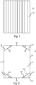
- Fig. 1 shows a front view of wear part 5 of a jaw crusher.
- the wear part is substantially rectangular when viewed from a front direction at a wear surface 10.
- the wear part 5 comprises at a first side the wear surface 10 which is during operation of the wear part directed to a crushing chamber of the crusher.
- Fig. 2 shows a rear view of the wear part 5.
- the wear part 5 comprises at a second side which is opposite to the first side a first counter surface 11 (rear surface) which is detachable fixable against the fixed or movable jaw of the crusher.
- a vertical first side 17 and a vertical second side 17' of the wear part are defining the width of the wear part.
- a horizontal first end 16 and a horizontal second end 16' of the wear part are defining the length of the wear part.
- planar surfaces are denoted with reference numbers 12 and 13 (12' and 13') at which planar surfaces the wear part 5 is thinner than at the broad first counter surface 11 (rear surface).
- the planar surfaces 12 and 13 are formed as for example a recesses to the first counter surface 11.
- planar surfaces 12 and 13 (12' and 13') are preferably located at both ends of the wear part wherein the wear part can be turned upside down when the first end 16 (bottom end) is more worn than the second end 16' (upper end) so optimizing the lifetime of the wear part.
- the wear part 5 comprises second counter surfaces 14 and 15 inclined in opposite directions, respective angles ⁇ and ⁇ , and 14' and 15', respective angles ⁇ ' and ⁇ ', for holding the wear part in place vertically and for holding the wear part in a centering way in place in side direction relative to the jaw of the jaw crusher.
- Two second counter surfaces 14, 15 inclined in opposite directions ⁇ and ⁇ are arranged to act as a pair in connection with the first end 16 of the wear part which second counter surfaces are centering the wear part in side direction. Further two second counter surfaces 14', 15' inclined in opposite directions ⁇ ' and ⁇ ' are arranged to act as a pair in connection with the second end 16' of the wear part which second counter surfaces are centering the wear part in side direction.
- the second counter surfaces 14, 15 (14', 15') located in side walls of recesses which are formed to the first counter surface 11 are intended, during mounting and operation, to face under compression the second fixing parts 73, 74, 75 ( Fig. 10 ) formed to the jaw of the crusher which comprise second fixing surfaces 76 acting as a counter shape such that the second counter surfaces and second fixing surfaces inclined in opposite directions relative to the first fixing surface 11 are acting as wedges inclined in two opposite directions.
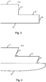
- Figs. 3 and 4 show alternative sections A-A of Fig. 2 .
- the bottom end 16 (upper end 16') of the wear part is perpendicular to the plane 12 and the first counter surface 11.
- the second counter surfaces 14 are, additionally to angles inclined in opposite directions shown in Fig. 2 , inclined in such a direction which is leading the first counter surface 11 against the jaw of the crusher, when the wear part is pressed vertically.
- the lower end 16 (upper end 16') of the wear part is forming an angle ⁇ ' relative to the plane 12 wherein the wear part can be set better in place to the jaw.
- a wedge-like fixing means can be arranged against the surface 16 (16') in the upper end of the jaw (pitman) which is forming to the wear part 5, in the longitudinal direction of the wear part (in this description the term vertical is also used) compressing fixing force and presses the wear part 5 against the first fixing surface of the jaw.
- a section of the recess formed in an edge of the first counter surface 11 is defining the second counter surface 14 (and 15; 14' and 15').
- Each second counter surface is formed to a side wall 14 (and 15; 14' and 15') of the recess which is formed in the first counter surface 11, and is forming, connected to the planar surface 12 (and 13; 12' and 13'), an inclined planar surface which can be in an angle of 90 degrees relative to the planar surface 12 (and 13; 12' and 13') (shown in Fig. 3 ) or in an angle ⁇ of less than 90 degrees relative to the planar surface 12 (and 13; 12' and 13') (shown in Fig. 4 ).
- the second counter surface 14 is forming an angle relative to the first counter surface 11 which is corresponding to the angle alfa. Additionally the first end 16 (bottom end) may be formed in an angle ⁇ ' relative to the surface 12, which angle is corresponding to the angle ⁇ , in a region which is located behind the region where the wear part 10 is exposed to wear (behind the dashed line depicted in Fig. 4 ), when viewed from the direction of the wear surface.
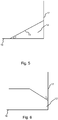
- Figs. 5 and 6 show alternative embodiments of counter surfaces inclined in opposite directions. Figs. 5 and 6 show the right-hand edge of the downwards directed end 16 of the wear part.
- the second counter surfaces (counter surface 14 shown) are arranged in a V-shape according to Fig. 2 .
- the contact surface of the centering angle part i.e. the second counter surface 14 is directed inclined downwards and right.
- the contact surface of the centering angle part, i.e. the second counter surface is directed inclined downwards and left.
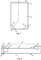
- Figs. 7 and 8 show a jaw 20 of a jaw crusher according to an embodiment of the invention.
- a front view of the jaw is shown in Fig. 7 .
- a side view of the jaw 20 is shown in Fig. 8 such that the first end of the wear part to be located against the first fixing surface 22, and the first end of the jaw are shown right, and and the second end of the wear part and the second end of the jaw are left.
- Fig. 8 shows a section A-B of the jaw in Fig. 7 to which jaw is fixed a wear part.
- the wear part is depicted with a dashed line.
- the wear surface 10 extends curved from the first end to the second end of the wear part.
- a wear part which comprises a similar first end (bottom end in Fig. 7 ) as the wear part 5 shown in Fig. 2 .
- the second end of the wear part to be fixed to the jaw 20 comprises a third counter surface inclined in one direction, and the fixing wedge to be tightened towards the jaw comprises correspondingly a third inclined fixing surface which faces the third counter surface.
- the wear part to be fixed through common act of said wedge-like third fixing surfaces and counter surfaces is pressed vertically in direction of the first end of the jaw and against the first fixing surface 22.
- the jaw comprises in the bottom end a two-part fixing wedge arrangement comprising second fixing parts 23 and 24 inclined in two directions, which second fixing parts are projecting from the plane defined by the first fixing surface 22 of the jaw.
- the second fixing parts with the jaw are formed of a solid piece by machining.
- the fixing parts (for example fixing wedges) may be formed exchangeable, i.e, fixable in a detachable way.
- the second fixing parts 23 and 24 comprise upper surfaces which are preferably planar and towards which the surfaces 13 and 12 set, when the wear part is mounted to the jaw.
- the jaw comprises in the second fixing parts 23, 24 second fixing surfaces 34 and 35 inclined in opposite directions against which the second counter surfaces 15 and 14 inclined in opposite directions of the wear part are intended to be placed.
- the second fixing surfaces 34 and 35 in the second end of the jaw are formed in between the upper surfaces of the second fixing parts 23, 24 and the first fixing surface 22 of the jaw.
- the first angle of the second fixing surfaces 34, 35 relative to the horizontal bottom end of the jaw is corresponding to the angle ⁇ of the wear part shown in Figs. 2 and 5
- the second angle of the second fixing surfaces 34, 35 relative to the first fixing surface 22 is corresponding to the angle ⁇ shown in Fig. 4 .
- the jaw 20 comprises a movable fixing wedge 21 by which the wear part is brought to vertical compression in the jaw such that the first counter surface (rear surface) of the wear part is pressed in a friction joint against the first counter surface 22 of the jaw.
- the fixing wedge 21 is tightened towards the jaw by a fixing means 26.
- a mounting wedge may in some cases be used in between the fixing wedge 21 and the inclined counter surface of the wear part which mounting wedge may have, in a simple case, a cross-section of a parallelogram (for example for making the mounting easier).
- Fig. 9 shows a side view of a fixing of a two-part (wear surfaces 10, 10') wear part by fixing wedges72, 73, 74, 75 in the section C-C of Fig. 10.
- Fig. 10 shows a front view of the fixing wedges of Fig. 9 having inclined surfaces 76.
- the fixing wedge 75 acting to the bottom end of the lower wear part comprises second fixing surfaces which are acting vertically upwards.
- the fixing wedge 74 between the wear parts comprises second fixing surfaces which are acting vertically upwards and downwards.
- the mounting wedge 73 acting to the upper end of the upper wear part comprises at its upper surface a third surface inclined in one direction, and at its bottom surface second fixing surfaces inclined in two directions which are acting vertically downwards.
- the uppermost fixing wedge 72 comprises at its bottom surface a surface which is acting against the surface inclined in one direction of the mounting wedge 73.
- the second fixing part 75 in the lower end of the jaw is formed by joining a separate fixing part to the jaw, for example to a shape such as a groove or a recess formed in the jaw.
- the fixing wedge 75 is preferably tightened in place at the beginning of the mounting, and the remaining fixing wedges are tightened when the wear parts are set in place.
- the joining of the fixing wedges 72, 74, 75 is made with bolts 77 in Fig. 10 .
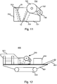
- Fig. 11 shows a jaw crusher 700.
- the body of the jaw crusher is formed of a front end 702 and a rear end 701 and side plates.
- a fixed jaw 703 is fixed to the front end of the jaw crusher and a stationary wear part which is receiving the crushing forces is fixed to the fixed jaw.
- a movable wear part is fixed to a movable jaw 704, i.e. the pitman, the eccentric movement of which movable wear part is generated by rotating an eccentric shaft.
- the wear parts and jaws are described in more detail in connection with for example Figs. 2 and 7 .
- the jaw crusher also comprises a belt wheel 705 which is connected to the eccentric, V-belts 707, a motor and a belt wheel 706 of the motor for moving the movable jaw 704.
- the rock material is crushed between the wear parts and is conveyed after the crushing for instance along a belt conveyor to further processing.
- Fig. 12 shows a movable track-based mineral material processing plant 800 which comprises a feeder 803.
- the feeder comprises also a conveyor.
- the processing plant comprises a crusher 700 such as the jaw crusher of Fig. 11 and a frame 801, a power unit 804, a discharge conveyor 805 and a track base 802.
- the mineral material processing plant may be moved also by other means such as wheels, runners or legs or it may also be a stationary plant.
Landscapes
- Engineering & Computer Science (AREA)
- Mechanical Engineering (AREA)
- Food Science & Technology (AREA)
- Crushing And Grinding (AREA)
- Working Measures On Existing Buildindgs (AREA)
Claims (12)
- Pièce d'usure (5) pour un concasseur à mâchoires, laquelle pièce d'usure comprend, au niveau d'un premier côté, une surface d'usure (10, 10') destinée à être dirigée vers une chambre de broyage du concasseur (700); et au niveau d'un second côté opposé, une première contre-surface (11) qui peut être fixée de manière amovible contre une mâchoire fixe (703) ou mobile (704) du concasseur ; caractérisée en ce que la pièce d'usure (5) comprend, en liaison avec une première extrémité (16) de la pièce d'usure au bas de la pièce d'usure, une paire de secondes contre-surfaces (14, 15 ; 14', 15') inclinées dans des directions opposées l'une par rapport à l'autre et par rapport à la première extrémité de la pièce d'usure, lesquelles secondes contre-surfaces sont agencées pour maintenir la pièce d'usure en position verticale et pour centrer la pièce d'usure dans une direction latérale par rapport à la mâchoire.
- Pièce d'usure selon la revendication 1, caractérisée en ce que deux secondes contre-surfaces (14, 15 ; 14', 15') inclinées dans des directions opposées sont agencées pour agir en tant que paire centrant la pièce d'usure (5) dans le sens latéral.
- Pièce d'usure selon la revendication 1 ou 2, caractérisée en ce que la seconde contre-surface (14, 15 ; 14', 15') est formée sur une paroi latérale d'un évidement qui est formé dans la première contre-surface (11).
- Pièce d'usure selon l'une quelconque des revendications 1 à 3, caractérisée en ce que les secondes contre-surfaces (14, 15; 14', 15') inclinées dans des directions opposées sont inclinées dans deux directions par rapport à la première contre-surface (11).
- Pièce d'usure selon l'une quelconque des revendications 1 à 4, caractérisée en ce que les secondes contre-surfaces (14, 15 ; 14', 15') sont, en plus de l'inclinaison dans des directions opposées, inclinées de manière à ce que les secondes contre-surfaces forment un angle supérieur à 270° avec la première contre-surface (11) de la pièce d'usure.
- Pièce d'usure selon l'une quelconque des revendications 1 à 5, caractérisée en ce que les secondes contre-surfaces (14, 15 ; 14', 15') sont disposées selon un angle (β) allant de 10° à 80° par rapport à une extrémité (16, 16') de la pièce d'usure.
- Pièce d'usure selon l'une quelconque des revendications 1 à 5, caractérisée en ce que les secondes contre-surfaces (14, 15 ; 14', 15') sont disposées selon un angle (γ) allant de 80° à 10° par rapport à un côté longitudinal (17) de la pièce d'usure.
- Concasseur à mâchoires comprenant deux mâchoires opposées (703, 704) qui forment entre elles une chambre de broyage de matériau minéral, dont au moins une première mâchoire (704) peut être déplacée vers une deuxième mâchoire (703) et à distance de la deuxième mâchoire, et au moins une mâchoire (703, 704) comprend, sur le côté de la chambre de broyage, une première surface de fixation (22) destinée à recevoir une première contre-surface (11) comprise dans une pièce d'usure (5) selon la revendication 1, pouvant être fixée de manière amovible; caractérisé en ce que ladite au moins une mâchoire (703, 704) comprend deux secondes surfaces de fixation (34, 35) inclinées dans des directions opposées pour recevoir une paire de secondes contre-surfaces (14, 15; 14 ', 15') comprise dans la pièce d'usure (5) en liaison avec une première extrémité (16) de la pièce d'usure au bas de la pièce d'usure et inclinée dans des directions opposées l'une par rapport à l'autre et par rapport à la première extrémité de la pièce d'usure selon la revendication 1, et agencées pour maintenir au moins une pièce d'usure en position verticale et pour centrer la pièce d'usure dans une direction latérale par rapport à une mâchoire fixe ou mobile.
- Concasseur à mâchoires selon la revendication 8, caractérisé en ce que le concasseur à mâchoires (700) comprend une pièce d'usure (5) selon l'une quelconque des revendications 1 à 7.
- Installation de traitement de matériau minéral (800), caractérisée en ce que l'installation de traitement de matériau minéral (800) comprend un concasseur à mâchoires (700) selon la revendication 8 ou 9.
- Procédé de fixation d'au moins une pièce d'usure (5) sur une mâchoire (703, 704) d'un concasseur à mâchoires (700) de manière amovible, le procédé comprenant l'étape consistant à placer l'une contre l'autre une première surface de fixation (22) comprise dans la mâchoire sur le côté d'une chambre de broyage du concasseur, et une première contre-surface (11) comprise dans la pièce d'usure, laquelle première contre-surface se trouve dans la pièce d'usure sur un côté opposé de la surface d'usure (10, 10') ; caractérisé en ce que le procédé comprend l'étape consistant à presser l'une contre l'autre deux secondes surfaces de fixation (34, 35) inclinées dans des directions opposées comprises dans la mâchoire (703, 704) et une paire de secondes contre-surfaces (14, 15 ; 14 ', 15') comprises dans la pièce d'usure (5) en liaison avec une première extrémité (16) de la pièce d'usure au bas de la pièce d'usure et inclinée dans des directions opposées l'une par rapport à l'autre et par rapport à la première extrémité de la pièce d'usure ; maintenant la pièce d'usure en position verticale et de manière centrée dans une direction latérale par rapport à une mâchoire fixe ou mobile du concasseur au moyen des secondes surfaces de fixation et des secondes contre-surfaces.
- Procédé selon la revendication 11, caractérisé par l'étape consistant à diriger une force de fixation sur la pièce d'usure (5) depuis au moins trois directions différentes.
Applications Claiming Priority (1)
| Application Number | Priority Date | Filing Date | Title |
|---|---|---|---|
| PCT/FI2012/050255 WO2013140014A1 (fr) | 2012-03-19 | 2012-03-19 | Pièce d'usure pour un concasseur à mâchoires, concasseur à mâchoires, traitement de matériaux minéraux et procédé pour la fixation d'une pièce d'usure |
Publications (2)
| Publication Number | Publication Date |
|---|---|
| EP2827992A1 EP2827992A1 (fr) | 2015-01-28 |
| EP2827992B1 true EP2827992B1 (fr) | 2017-05-17 |
Family
ID=46001296
Family Applications (1)
| Application Number | Title | Priority Date | Filing Date |
|---|---|---|---|
| EP12716480.4A Active EP2827992B1 (fr) | 2012-03-19 | 2012-03-19 | Pièce d'usure pour un concasseur à mâchoires, concasseur à mâchoires, traitement de matériaux minéraux et procédé pour la fixation d'une pièce d'usure |
Country Status (5)
| Country | Link |
|---|---|
| US (1) | US9724696B2 (fr) |
| EP (1) | EP2827992B1 (fr) |
| CN (1) | CN104203414B (fr) |
| BR (1) | BR112014022038B8 (fr) |
| WO (1) | WO2013140014A1 (fr) |
Families Citing this family (2)
| Publication number | Priority date | Publication date | Assignee | Title |
|---|---|---|---|---|
| EP3296470B1 (fr) | 2016-09-15 | 2019-05-08 | Caterpillar Work Tools B. V. | Pièce de travail remplaçable pour un outil de démolition |
| AU2019101547A4 (en) * | 2018-12-11 | 2020-01-23 | Orbis Mining Pty Ltd | Crushing of core samples |
Family Cites Families (7)
| Publication number | Priority date | Publication date | Assignee | Title |
|---|---|---|---|---|
| GB190909454A (en) | 1909-04-21 | 1910-01-13 | Samuel Osborn | Improvements in Crushing Machines and in Appliances connected therewith. |
| GB214371A (en) | 1923-02-07 | 1924-04-24 | William John Drain | Improvements in or relating to stone crushing or breaking machines |
| US3804345A (en) | 1972-09-15 | 1974-04-16 | Barber Greene Co | Jaw crusher die mounting |
| CN2228372Y (zh) * | 1995-03-28 | 1996-06-05 | 张富和 | 鄂式破碎机用鄂板 |
| FI103329B1 (fi) | 1997-12-22 | 1999-06-15 | Nordberg Lokomo Oy | Tapa leukamurskaimen kulutusleuan kiinnittämiseksi ja leukamurskain |
| US6155507A (en) | 1999-03-20 | 2000-12-05 | Cedarapids, Inc. | Device for securing the stationary jaw of a jaw crusher |
| JP2001170507A (ja) | 1999-12-16 | 2001-06-26 | Nakayama Iron Works Ltd | ジョークラッシャにおける可動歯板の下部支持構造 |
-
2012
- 2012-03-19 CN CN201280071634.5A patent/CN104203414B/zh active Active
- 2012-03-19 BR BR112014022038A patent/BR112014022038B8/pt active IP Right Grant
- 2012-03-19 EP EP12716480.4A patent/EP2827992B1/fr active Active
- 2012-03-19 US US14/385,678 patent/US9724696B2/en active Active
- 2012-03-19 WO PCT/FI2012/050255 patent/WO2013140014A1/fr active Application Filing
Also Published As
| Publication number | Publication date |
|---|---|
| WO2013140014A1 (fr) | 2013-09-26 |
| EP2827992A1 (fr) | 2015-01-28 |
| CN104203414A (zh) | 2014-12-10 |
| US9724696B2 (en) | 2017-08-08 |
| CN104203414B (zh) | 2017-09-15 |
| BR112014022038B8 (pt) | 2023-04-25 |
| BR112014022038B1 (pt) | 2021-04-20 |
| US20150048190A1 (en) | 2015-02-19 |
Similar Documents
| Publication | Publication Date | Title |
|---|---|---|
| JP3231617B2 (ja) | ジョークラッシャ | |
| JPH01228562A (ja) | ジョークラッシャ | |
| RU2212938C2 (ru) | Щековая дробилка | |
| EP2827992B1 (fr) | Pièce d'usure pour un concasseur à mâchoires, concasseur à mâchoires, traitement de matériaux minéraux et procédé pour la fixation d'une pièce d'usure | |
| EP3122462A1 (fr) | Broyeur à mâchoires, installation de broyage et procédé pour utiliser un broyeur à mâchoires | |
| AU2013366340B2 (en) | A mineral material feed apparatus, a plant and a method | |
| KR101955505B1 (ko) | 모래 제조 겸용 골재 파쇄기 | |
| WO2018113959A1 (fr) | Châssis de support de concasseur à mâchoires | |
| WO2013171361A1 (fr) | Broyeur à mâchoires, installation de broyage et procédé de broyage | |
| EP2482984B1 (fr) | Extrémité avant de structure de broyeur à mâchoires, broyeur à mâchoires et installation de broyage | |
| US9283564B2 (en) | Frame of jaw crusher, jaw crusher and crushing plant | |
| US2449746A (en) | Wear plate for jaw crushers | |
| AU2018253821B2 (en) | Crusher assembly for a jaw crusher | |
| US11103873B2 (en) | Jaw plate retainer | |
| KR200345951Y1 (ko) | 석탄 컨베이어 벨트의 슈트라이너 고정장치 | |
| US20200016601A1 (en) | Jaw plate for a jaw crusher | |
| JP2012170882A (ja) | 磨耗交換部材 | |
| JP2006181413A (ja) | 破砕装置 |
Legal Events
| Date | Code | Title | Description |
|---|---|---|---|
| PUAI | Public reference made under article 153(3) epc to a published international application that has entered the european phase |
Free format text: ORIGINAL CODE: 0009012 |
|
| 17P | Request for examination filed |
Effective date: 20140917 |
|
| AK | Designated contracting states |
Kind code of ref document: A1 Designated state(s): AL AT BE BG CH CY CZ DE DK EE ES FI FR GB GR HR HU IE IS IT LI LT LU LV MC MK MT NL NO PL PT RO RS SE SI SK SM TR |
|
| AX | Request for extension of the european patent |
Extension state: BA ME |
|
| DAX | Request for extension of the european patent (deleted) | ||
| 17Q | First examination report despatched |
Effective date: 20150922 |
|
| GRAP | Despatch of communication of intention to grant a patent |
Free format text: ORIGINAL CODE: EPIDOSNIGR1 |
|
| INTG | Intention to grant announced |
Effective date: 20161208 |
|
| RAP1 | Party data changed (applicant data changed or rights of an application transferred) |
Owner name: METSO MINERALS, INC. |
|
| GRAS | Grant fee paid |
Free format text: ORIGINAL CODE: EPIDOSNIGR3 |
|
| GRAA | (expected) grant |
Free format text: ORIGINAL CODE: 0009210 |
|
| AK | Designated contracting states |
Kind code of ref document: B1 Designated state(s): AL AT BE BG CH CY CZ DE DK EE ES FI FR GB GR HR HU IE IS IT LI LT LU LV MC MK MT NL NO PL PT RO RS SE SI SK SM TR |
|
| REG | Reference to a national code |
Ref country code: GB Ref legal event code: FG4D |
|
| REG | Reference to a national code |
Ref country code: CH Ref legal event code: EP |
|
| REG | Reference to a national code |
Ref country code: IE Ref legal event code: FG4D |
|
| REG | Reference to a national code |
Ref country code: AT Ref legal event code: REF Ref document number: 893980 Country of ref document: AT Kind code of ref document: T Effective date: 20170615 |
|
| REG | Reference to a national code |
Ref country code: DE Ref legal event code: R096 Ref document number: 602012032532 Country of ref document: DE |
|
| REG | Reference to a national code |
Ref country code: SE Ref legal event code: TRGR |
|
| REG | Reference to a national code |
Ref country code: NL Ref legal event code: MP Effective date: 20170517 |
|
| REG | Reference to a national code |
Ref country code: LT Ref legal event code: MG4D |
|
| REG | Reference to a national code |
Ref country code: AT Ref legal event code: MK05 Ref document number: 893980 Country of ref document: AT Kind code of ref document: T Effective date: 20170517 |
|
| PG25 | Lapsed in a contracting state [announced via postgrant information from national office to epo] |
Ref country code: AT Free format text: LAPSE BECAUSE OF FAILURE TO SUBMIT A TRANSLATION OF THE DESCRIPTION OR TO PAY THE FEE WITHIN THE PRESCRIBED TIME-LIMIT Effective date: 20170517 Ref country code: HR Free format text: LAPSE BECAUSE OF FAILURE TO SUBMIT A TRANSLATION OF THE DESCRIPTION OR TO PAY THE FEE WITHIN THE PRESCRIBED TIME-LIMIT Effective date: 20170517 Ref country code: NO Free format text: LAPSE BECAUSE OF FAILURE TO SUBMIT A TRANSLATION OF THE DESCRIPTION OR TO PAY THE FEE WITHIN THE PRESCRIBED TIME-LIMIT Effective date: 20170817 Ref country code: GR Free format text: LAPSE BECAUSE OF FAILURE TO SUBMIT A TRANSLATION OF THE DESCRIPTION OR TO PAY THE FEE WITHIN THE PRESCRIBED TIME-LIMIT Effective date: 20170818 Ref country code: LT Free format text: LAPSE BECAUSE OF FAILURE TO SUBMIT A TRANSLATION OF THE DESCRIPTION OR TO PAY THE FEE WITHIN THE PRESCRIBED TIME-LIMIT Effective date: 20170517 Ref country code: ES Free format text: LAPSE BECAUSE OF FAILURE TO SUBMIT A TRANSLATION OF THE DESCRIPTION OR TO PAY THE FEE WITHIN THE PRESCRIBED TIME-LIMIT Effective date: 20170517 |
|
| PG25 | Lapsed in a contracting state [announced via postgrant information from national office to epo] |
Ref country code: IS Free format text: LAPSE BECAUSE OF FAILURE TO SUBMIT A TRANSLATION OF THE DESCRIPTION OR TO PAY THE FEE WITHIN THE PRESCRIBED TIME-LIMIT Effective date: 20170917 Ref country code: LV Free format text: LAPSE BECAUSE OF FAILURE TO SUBMIT A TRANSLATION OF THE DESCRIPTION OR TO PAY THE FEE WITHIN THE PRESCRIBED TIME-LIMIT Effective date: 20170517 Ref country code: NL Free format text: LAPSE BECAUSE OF FAILURE TO SUBMIT A TRANSLATION OF THE DESCRIPTION OR TO PAY THE FEE WITHIN THE PRESCRIBED TIME-LIMIT Effective date: 20170517 Ref country code: PL Free format text: LAPSE BECAUSE OF FAILURE TO SUBMIT A TRANSLATION OF THE DESCRIPTION OR TO PAY THE FEE WITHIN THE PRESCRIBED TIME-LIMIT Effective date: 20170517 Ref country code: RS Free format text: LAPSE BECAUSE OF FAILURE TO SUBMIT A TRANSLATION OF THE DESCRIPTION OR TO PAY THE FEE WITHIN THE PRESCRIBED TIME-LIMIT Effective date: 20170517 Ref country code: BG Free format text: LAPSE BECAUSE OF FAILURE TO SUBMIT A TRANSLATION OF THE DESCRIPTION OR TO PAY THE FEE WITHIN THE PRESCRIBED TIME-LIMIT Effective date: 20170817 |
|
| PG25 | Lapsed in a contracting state [announced via postgrant information from national office to epo] |
Ref country code: EE Free format text: LAPSE BECAUSE OF FAILURE TO SUBMIT A TRANSLATION OF THE DESCRIPTION OR TO PAY THE FEE WITHIN THE PRESCRIBED TIME-LIMIT Effective date: 20170517 Ref country code: DK Free format text: LAPSE BECAUSE OF FAILURE TO SUBMIT A TRANSLATION OF THE DESCRIPTION OR TO PAY THE FEE WITHIN THE PRESCRIBED TIME-LIMIT Effective date: 20170517 Ref country code: RO Free format text: LAPSE BECAUSE OF FAILURE TO SUBMIT A TRANSLATION OF THE DESCRIPTION OR TO PAY THE FEE WITHIN THE PRESCRIBED TIME-LIMIT Effective date: 20170517 Ref country code: SK Free format text: LAPSE BECAUSE OF FAILURE TO SUBMIT A TRANSLATION OF THE DESCRIPTION OR TO PAY THE FEE WITHIN THE PRESCRIBED TIME-LIMIT Effective date: 20170517 Ref country code: CZ Free format text: LAPSE BECAUSE OF FAILURE TO SUBMIT A TRANSLATION OF THE DESCRIPTION OR TO PAY THE FEE WITHIN THE PRESCRIBED TIME-LIMIT Effective date: 20170517 |
|
| REG | Reference to a national code |
Ref country code: DE Ref legal event code: R097 Ref document number: 602012032532 Country of ref document: DE |
|
| PG25 | Lapsed in a contracting state [announced via postgrant information from national office to epo] |
Ref country code: SM Free format text: LAPSE BECAUSE OF FAILURE TO SUBMIT A TRANSLATION OF THE DESCRIPTION OR TO PAY THE FEE WITHIN THE PRESCRIBED TIME-LIMIT Effective date: 20170517 Ref country code: IT Free format text: LAPSE BECAUSE OF FAILURE TO SUBMIT A TRANSLATION OF THE DESCRIPTION OR TO PAY THE FEE WITHIN THE PRESCRIBED TIME-LIMIT Effective date: 20170517 |
|
| PLBE | No opposition filed within time limit |
Free format text: ORIGINAL CODE: 0009261 |
|
| STAA | Information on the status of an ep patent application or granted ep patent |
Free format text: STATUS: NO OPPOSITION FILED WITHIN TIME LIMIT |
|
| REG | Reference to a national code |
Ref country code: FR Ref legal event code: PLFP Year of fee payment: 7 |
|
| 26N | No opposition filed |
Effective date: 20180220 |
|
| PG25 | Lapsed in a contracting state [announced via postgrant information from national office to epo] |
Ref country code: SI Free format text: LAPSE BECAUSE OF FAILURE TO SUBMIT A TRANSLATION OF THE DESCRIPTION OR TO PAY THE FEE WITHIN THE PRESCRIBED TIME-LIMIT Effective date: 20170517 |
|
| REG | Reference to a national code |
Ref country code: CH Ref legal event code: PL |
|
| PG25 | Lapsed in a contracting state [announced via postgrant information from national office to epo] |
Ref country code: MC Free format text: LAPSE BECAUSE OF FAILURE TO SUBMIT A TRANSLATION OF THE DESCRIPTION OR TO PAY THE FEE WITHIN THE PRESCRIBED TIME-LIMIT Effective date: 20170517 |
|
| REG | Reference to a national code |
Ref country code: BE Ref legal event code: MM Effective date: 20180331 |
|
| REG | Reference to a national code |
Ref country code: IE Ref legal event code: MM4A |
|
| PG25 | Lapsed in a contracting state [announced via postgrant information from national office to epo] |
Ref country code: LU Free format text: LAPSE BECAUSE OF NON-PAYMENT OF DUE FEES Effective date: 20180319 |
|
| PG25 | Lapsed in a contracting state [announced via postgrant information from national office to epo] |
Ref country code: IE Free format text: LAPSE BECAUSE OF NON-PAYMENT OF DUE FEES Effective date: 20180319 |
|
| PG25 | Lapsed in a contracting state [announced via postgrant information from national office to epo] |
Ref country code: LI Free format text: LAPSE BECAUSE OF NON-PAYMENT OF DUE FEES Effective date: 20180331 Ref country code: CH Free format text: LAPSE BECAUSE OF NON-PAYMENT OF DUE FEES Effective date: 20180331 Ref country code: BE Free format text: LAPSE BECAUSE OF NON-PAYMENT OF DUE FEES Effective date: 20180331 |
|
| PG25 | Lapsed in a contracting state [announced via postgrant information from national office to epo] |
Ref country code: MT Free format text: LAPSE BECAUSE OF NON-PAYMENT OF DUE FEES Effective date: 20180319 |
|
| PG25 | Lapsed in a contracting state [announced via postgrant information from national office to epo] |
Ref country code: PT Free format text: LAPSE BECAUSE OF FAILURE TO SUBMIT A TRANSLATION OF THE DESCRIPTION OR TO PAY THE FEE WITHIN THE PRESCRIBED TIME-LIMIT Effective date: 20170517 Ref country code: HU Free format text: LAPSE BECAUSE OF FAILURE TO SUBMIT A TRANSLATION OF THE DESCRIPTION OR TO PAY THE FEE WITHIN THE PRESCRIBED TIME-LIMIT; INVALID AB INITIO Effective date: 20120319 |
|
| PG25 | Lapsed in a contracting state [announced via postgrant information from national office to epo] |
Ref country code: MK Free format text: LAPSE BECAUSE OF NON-PAYMENT OF DUE FEES Effective date: 20170517 Ref country code: CY Free format text: LAPSE BECAUSE OF FAILURE TO SUBMIT A TRANSLATION OF THE DESCRIPTION OR TO PAY THE FEE WITHIN THE PRESCRIBED TIME-LIMIT Effective date: 20170517 |
|
| PG25 | Lapsed in a contracting state [announced via postgrant information from national office to epo] |
Ref country code: AL Free format text: LAPSE BECAUSE OF FAILURE TO SUBMIT A TRANSLATION OF THE DESCRIPTION OR TO PAY THE FEE WITHIN THE PRESCRIBED TIME-LIMIT Effective date: 20170517 |
|
| PGFP | Annual fee paid to national office [announced via postgrant information from national office to epo] |
Ref country code: FR Payment date: 20230221 Year of fee payment: 12 Ref country code: FI Payment date: 20230315 Year of fee payment: 12 |
|
| REG | Reference to a national code |
Ref country code: DE Ref legal event code: R081 Ref document number: 602012032532 Country of ref document: DE Owner name: METSO MINERALS, INC., FI Free format text: FORMER OWNER: METSO MINERALS, INC., HELSINKI, FI |
|
| PGFP | Annual fee paid to national office [announced via postgrant information from national office to epo] |
Ref country code: TR Payment date: 20230317 Year of fee payment: 12 Ref country code: SE Payment date: 20230210 Year of fee payment: 12 |
|
| P01 | Opt-out of the competence of the unified patent court (upc) registered |
Effective date: 20230627 |
|
| PGFP | Annual fee paid to national office [announced via postgrant information from national office to epo] |
Ref country code: FI Payment date: 20240315 Year of fee payment: 13 Ref country code: DE Payment date: 20240206 Year of fee payment: 13 Ref country code: GB Payment date: 20240201 Year of fee payment: 13 |