EP2827067A2 - Cadre central pour hotte aspirante et hotte aspirante - Google Patents
Cadre central pour hotte aspirante et hotte aspirante Download PDFInfo
- Publication number
- EP2827067A2 EP2827067A2 EP14176484.5A EP14176484A EP2827067A2 EP 2827067 A2 EP2827067 A2 EP 2827067A2 EP 14176484 A EP14176484 A EP 14176484A EP 2827067 A2 EP2827067 A2 EP 2827067A2
- Authority
- EP
- European Patent Office
- Prior art keywords
- central frame
- module
- fan
- interface
- modules
- Prior art date
- Legal status (The legal status is an assumption and is not a legal conclusion. Google has not performed a legal analysis and makes no representation as to the accuracy of the status listed.)
- Granted
Links
- 239000002184 metal Substances 0.000 description 5
- 238000010276 construction Methods 0.000 description 4
- 235000013305 food Nutrition 0.000 description 4
- 238000009434 installation Methods 0.000 description 4
- 238000009423 ventilation Methods 0.000 description 4
- 210000004907 gland Anatomy 0.000 description 3
- 238000004519 manufacturing process Methods 0.000 description 3
- 230000000087 stabilizing effect Effects 0.000 description 3
- 239000011521 glass Substances 0.000 description 2
- 238000001746 injection moulding Methods 0.000 description 2
- 235000013599 spices Nutrition 0.000 description 2
- 239000004519 grease Substances 0.000 description 1
- 238000011900 installation process Methods 0.000 description 1
- 230000010354 integration Effects 0.000 description 1
- 238000007726 management method Methods 0.000 description 1
- 239000000463 material Substances 0.000 description 1
- 238000000034 method Methods 0.000 description 1
- 238000000465 moulding Methods 0.000 description 1
- 239000000243 solution Substances 0.000 description 1
- 239000000725 suspension Substances 0.000 description 1
Images

Classifications
-
- F—MECHANICAL ENGINEERING; LIGHTING; HEATING; WEAPONS; BLASTING
- F24—HEATING; RANGES; VENTILATING
- F24C—DOMESTIC STOVES OR RANGES ; DETAILS OF DOMESTIC STOVES OR RANGES, OF GENERAL APPLICATION
- F24C15/00—Details
- F24C15/20—Removing cooking fumes
Definitions
- the invention relates to a central frame for an extractor hood and an extractor hood with a central frame.
- an extractor housing is required, for example, on the underside of which a rail system for the drawer or the screen can be fastened.
- a so-called fan module such an attachment is not needed.
- the invention is therefore an object of the invention to provide a solution by means of which a simpler production of a cooker hood still great flexibility in the design of the hood can be guaranteed.
- the invention is based on the finding that this object can be achieved by a central component is used in a cooker hood that serves as a stabilizing element for all device variants.
- the invention therefore relates to a central frame for an extractor hood.
- the central frame is characterized in that it has at least one first interface for alternately connecting to at least two different fan modules and at least one second interface for alternately connecting to at least two different inlet modules.
- a connecting element which is open at least at the top and bottom.
- On the sides of the central frame is preferably closed.
- the central frame therefore has continuous side surfaces.
- In the continuous side surfaces of the central frame may preferably be introduced openings or the side surfaces in another way, for example, be interrupted by folds. These openings or interruptions may extend over a height and width which is less than the height and width of the respective side surface.
- a central frame which is closed on the sides that is to say has all the side walls, optionally with openings provided therein, it is also possible that at least one side surface is completely recessed in the central frame.
- the central frame for example, have only a rear wall or a rear wall and two side walls, but is open to the front or to the rear.
- the central frame therefore preferably has at least three walls which form the side surfaces.
- the central frame can be made, for example, in one piece as a deep-drawn part or as a welded joint part, or in several parts.
- the central frame can be selectively connected to one of the fan modules or the other of the fan modules. An exchange of the fan modules on the central frame itself can be done but is not required.
- the central frame can be optionally connected to one of the on-board modules or the other of the modules. An exchange of the wall modules on the central frame itself can be done but is not required.
- fan module variants As different fan modules that can be selectively connected to the first interface of the central frame, this is preferably understood as different fan module variants. These fan module variants differ in their construction. However, interfaces at the different fan module variants are preferably specifically defined and shaped in order to be able to realize a connection to a single variant of the central frame. In particular, the dimensions of the fan module variants are preferably the same in the region of the interface in which they are connected to the central frame. However, it is also within the scope of the invention that the central frame is modified for different fan module variants. Preferably, however, the first interface of the central frame is also listed in this embodiment so that at least two different fan modules can be alternately attached to the central frame.
- intake module variants differ in their construction.
- interfaces on the different intake module variants are specifically defined and shaped in order to be able to realize a connection to a single variant of the central frame.
- the dimensions of the vent module variants are preferably the same in the region of the interface in which they are connected to the central frame.
- the central frame is modified for different module variants.
- the first interface of the central frame is listed so that at least two different modules can be alternately attached to the central frame.
- a region of the central frame understood at this with the exhaust module or the fan module directly or indirectly can be connected.
- the direct connection can be done for example by inserting, creating or plugging the respective module in the central frame or vice versa.
- the indirect connection can be done for example via fasteners such as locking elements, screws, rivets and the like.
- the first interface for alternately connecting to at least two different fan modules may be formed by part of the surface of the central frame, by an edge of the central frame and / or by openings, recesses, folds, tabs or other connecting elements on the central frame.
- the connection between the center frame and the fan module is created by abutment.
- the fan module can be screwed, riveted or locked to the central frame, for example.
- the second interface for alternately connecting to at least two different lapping modules can be formed by a part of the surface of the central frame and / or openings, recesses, folds, tabs or other connecting elements on the central frame.
- the connection between the central frame and the on-wall module is created by abutment.
- an edge region of a wall module abut against an edge region of the central frame and be held by this.
- the on-off module can for example be screwed, riveted or locked to the central frame.
- a module is referred to in the context of the present invention, which comprises at least the extractor housing, in which the at least one fan, which can also be referred to as a fan, can be recorded or recorded.
- the fan is provided in the extractor housing in a fan housing which closely surrounds the actual fan, for example the fan wheel, and so on supports the generation of the ventilation flow.
- the fan housing for example, a screw housing or spiral housing or twin screw housing represent.
- the extractor housing is usually a rectangular housing, on which an air outlet is provided, can be derived via the air from the hood into a pipe or a hose.
- the extractor housing has an inlet opening, can pass through the air to the inlet surface of the fan housing and over to the fan. In the extractor housing, therefore, the air is conducted to the inlet surface of the fan housing.
- the electronics that is necessary for operating the fan is usually provided in or on the extractor housing.
- a ventilation module which is also referred to as a design module
- the module of the extractor hood is understood, in which a suction opening is formed, can enter through the air into the hood.
- the incoming air is passed through the vent module to the inlet of the extractor housing.
- Means for enlarging the suction opening of the extractor hood can also be provided on the vent module.
- an extendable or extendable drawer or an extendable or extendable screen can be provided.
- the vent module thus also includes the inflow geometry, is passed over the air from the suction port to the inlet opening of the fan module and in particular the extractor hood.
- a connecting element is created, via which the main components of the extractor hood, namely the fan module and the oncoming module, can be connected to one another. Since this connecting element is also designed separately from these two main components, additional functions can be taken over by the central frame.
- the central frame serves to stabilize the overall structure of the extractor hood, that is to say as a stabilizing element, and on the other hand, further components of the extractor hood can be provided on this central frame.
- the flexibility in the design of the extractor hood can thus be increased without this requiring an increased number of parts.
- the side of the central frame, on which the interface is provided for connection to different fan modules, can always be made the same despite completely different fan module variants which are connected to the central frame.
- the shape of the central frame in the area of the second interface is preferably the same for all types of infeed modules.
- a holding device for the guidance of the drawer can be provided for a vent module with an extendable drawer in the region of the second interface to the central frame.
- a central frame can be used in which such a holding device is recessed.
- the first interface is provided in the upper region of the central frame and the second interface is provided in the lower region of the central frame.
- the upper area means in this context at the top of the central frame and / or on the inside, outside or in the wall of the central frame near the upper edge of the central frame.
- the lower area means in this context at the lower edge and / or on the inside, outside or in the wall of the central frame near the lower edge of the central frame.
- the central frame in the upper part of a first interface for alternately connecting with at least two different fan modules and in the lower area has a second interface for alternately connecting with at least two different wall modules, the central frame serves as an intermediate element of the hood.
- the central frame is thus arranged between the intake module and the fan module and connects them. It can therefore be provided in the lower area, for example, a number of attachment points, such as openings for locking elements or passages for screws, without these conflict with connection points that are required for connection to the fan module.
- connection points for at least two different fan modules and / or connection points for at least two different input modules are provided at the first interface.
- the connection points for different fan module variants can be equal to each other and also the connection points for the different intake module variants can be the same. In this case, a single connection point can be used to connect different modules. But it is also possible that connection points for different fan module variants and / or different module variants must be designed differently.
- connection points may be provided on the central frame, but only a part of the connection points is used in the connection of a module variant.
- the advantage of the provision of connection points for different module variants is that the central frame can be used even more flexibly, in particular for different combinations of module variants, without having to make any structural changes to the central frame.
- connection points according to the invention for example, openings for locking elements, passages for screws or rivets, projections, folds, tabs or recesses understood, by means of which a connection between the central frame and the fan module or the wall module optionally made using other fasteners, such as screws, rivets or locking elements can be.
- the central frame is designed in one piece.
- the two side walls and the rear wall and, if provided, the front wall are manufactured in one part.
- the central frame may for example be bent and welded from a sheet metal or be made for example by injection molding of plastic.
- the advantage of the one-piece embodiment is the increased stability possessed by such an integral component.
- An embodiment of the central frame in which the central frame comprises only three side surfaces, is preferably configured in one piece, that is, is formed by a U-shaped part.
- the central frame can also be designed in several parts.
- the central frame may be configured in two parts.
- a U-part form the back and the side surfaces of the central frame.
- This U-part is then connected to a flat part that forms the front.
- a U-part can form the front side and the side surfaces of the central frame.
- This U-part is then connected to a flat part that forms the back.
- two L-parts together, wherein one of the L-parts forms the front of the central frame and a side surface and the second L-part forms the back of the central frame and the other side surface.
- the central frame in four parts, one part representing the front, one the back and the two other parts the side surfaces.
- connection points such as openings for locking devices or passages for screws can be easily introduced.
- the parts of the central frame in the multi-part design can be connected to each other for example via screw, plug, clinch or welded joints.
- the central frame has at least one fastening device for fastening the extractor hood in a kitchen cupboard.
- This fastening device may be at least partially formed on the central frame or attached thereto.
- attachment points for example in the form of openings for locking elements or fferauslässe or domes are preferably provided.
- the integration of a part of the fastening device on the central frame can be done for example by molding during injection molding.
- the fastening device is a Absenkrahmen which is fixed to the central frame.
- Absenkrahmen a device is understood, by means of which the central frame and thus the entire extractor hood is held in a kitchen cabinet and can be moved in the vertical direction.
- the Absenkrahmen has for this purpose a movable part which is fixed to the central frame and another part of the Absenkrahmens can then be attached to the kitchen cabinet. Also in this embodiment, the number of parts is reduced during assembly in the kitchen cabinet and therefore simplifies the assembly.
- the central frame may have at least one holding device for further components of the extractor hood. These other components may be separate parts to or connected to the fan module and the vent module. By allowing the central frame to hold further components, the overall structure of the central frame is further simplified.
- the holding devices may be, for example, openings, passages, protrusions, depressions, tabs, openings or folds.
- a holding device for further components of the extractor hood for example, represent a holding device for a filter element, such as an odor filter or grease filter.
- This holding device is preferably provided on the inside of the central frame.
- the central frame may comprise at least one holding device for at least one cable.
- This holding device may be provided as a cable guide in the form of a cable channel and be provided on the inside or the outside.
- the cable channel can in this case be integrally formed on or attached to the central frame. Also in this embodiment, the assembly of the hood in the kitchen cabinet is simplified.
- a retaining device for a movable part of the Ansauggeometrie in particular a rail system for a pull-out drawer may be additionally or alternatively provided on the central frame.
- This holding device is therefore provided in the lower region of the central frame.
- the central frame can thus be used as a stable connection point of standardized components, which are used in all device variants, where the central frame is used, such as a suspension system for the cabinet installation of the hood, filter mounts, cable management, accessories, such as lowering frame and many other components.
- a suspension system for the cabinet installation of the hood for extractor hoods with an extendable Drawer, also referred to as flat screen hoods
- accessories such as lowering frame and many other components.
- lowering frame and many other components are preferably rail systems, which may be referred to as telescopic rails, mounted directly to the central frame and connected to the drawer to ensure a stable and uniform guidance of the drawer.
- the invention in another aspect, relates to an extractor hood having a fan module and a vent module.
- the extractor hood is characterized in that the fan module is connected to the intake module via a central frame according to the invention.
- An inventively constructed extractor hood can be designed to be flexible in a simple manner.
- the interfaces on both the central frame and on the modules to be connected are specifically defined and shaped to unify the connection of the central frame to the various modules.
- uniform assembly processes can be achieved in the assembly of the extractor hood and there are no unnecessary parts variants, for example, from the central frame or the modules to be connected, because the interfaces are preferably the same.
- the inflow module and the fan module preferably have defined interfaces which are adapted to the interfaces on the central frame according to the invention.
- at least the dimensions of the central frame in the region of the first and second interface preferably correspond in each case to the dimensions of the fan module and the wall module in the areas of the interfaces provided thereon.
- Connection points that are necessary for the connection between the central frame and the ventilation module or between the central frame and fan module may vary from module variant to module variant, if necessary. This variation can be accommodated by providing a plurality of alternative attachment points to the central frame.
- the extractor hood preferably represents a built-in extractor hood.
- the advantage of the present invention can be used particularly well by providing fastening devices, such as, for example, a lowering frame.
- the extractor hood is a food.
- the fan module and the oncoming module are connected to each other via a central frame.
- the central frame for example, a holding device for the fireplace of the Esse.
- FIG. 1 an embodiment of the central frame is shown schematically.
- the top and bottom of the central frame 10 are open.
- the front, back and side surfaces of the center frame 10 are formed by a front wall 103, the rear wall 104, and right and left side walls 105, 106.
- the central frame 10 is made in one piece.
- the walls 103, 104, 105 and 106 together form the base body 100 of the central frame 10 and will also be referred to collectively as the base body 100 below.
- the main body 100 of the central frame 10 is formed only by three walls, in particular the rear wall 104 and the side walls 105, 106. In this embodiment, not shown, the central frame 10 is then open to the front.
- the central frame 10 has a first interface 101 for alternately connecting to at least two different fan modules 11 (see FIG. 2 ) on.
- the central frame 10 has a second interface for alternately connecting with at least two different wall modules 12 (see FIG. 2 ) on.
- the first interface 101 comprises the upper edge 1010 of the central frame 10, that is, of the main body 100 of the central frame 10.
- an outwardly directed step hereinafter is referred to as outer step 1011 or upper outer step, introduced into the wall of the base 100.
- step 1011 may be dispensed with.
- bends may be provided on the upper side of the central frame 10, through which a part of the upper edge 101 is bent inwards.
- connection points 1012, 1013 are provided for fan modules 11 in the front wall 103 and the rear wall.
- the attachment points 1012 and 1013 are in FIG. 1 shown schematically as openings. However, it is also within the scope of the invention that these connection points represent, for example, screw domes, lugs, folds, points or latching elements.
- the outer attachment points 1012 and the central attachment points 1012 in the middle of the upper region of the front wall 103 and the rear wall 104 are attachment points for a first fan module 11. These attachment points 1012 are therefore positioned and dimensioned according to connection means on the lower edge of the first fan module 11.
- connection points 1013 for a second fan module 11 are provided on the first interface 101.
- attachment points 1012 are offset inwards to the outer attachment points 1012. These attachment points 1013 are positioned and dimensioned such that they can interact with connection means on the second fan module 11. Therefore, optionally a first or a second fan module 11 can be fastened to the central frame 10 via the first interface 101.
- the second interface 102 in the illustrated embodiment comprises the lower edge 1023 of the central frame 10, that is, the main body 100 of the central frame 10.
- an outwardly directed step hereinafter is referred to as outer step 1024 or lower outer stage, introduced into the wall of the base body 100.
- connection points 1021, 1022 for inlet modules 12 are also provided in the front wall 103.
- the attachment points 1021 and 1022 are in FIG. 1 shown schematically as openings. However, it is also within the scope of the invention that these attachment points represent, for example, screw domes or locking elements.
- the outer attachment points 1021 are attachment points for a first gland module 12.
- connection points 1021 are therefore positioned and dimensioned according to connection means at the upper edge of the first gland module 12.
- connection points 1022 are provided for a second vent module 12. These are offset inwards to the outer connection points 1021.
- These attachment points 1022 are positioned and dimensioned to cooperate with connection means on the second gland module 12.
- a recess 1020 is also provided on the front wall 103 in the illustrated embodiment. This extends in the illustrated embodiment over the entire width of the front wall 103 and extends up to the outer step 1024.
- connection modules 12 to connect to the central frame 10 having a sliding drawer 120.
- This drawer 120 can at least partially engage in the recess 1020 of the central frame 10.
- the recess may therefore be referred to as a holding device or part of a holding device.
- holding devices 107 for holding rails of such a drawer 120 are also provided in the illustrated embodiment. In FIG. 1 the holding devices 107 are shown as openings. But it can also be provided other forms of holding devices, such as projections or holes.
- fastening devices may be provided in or on the base body 100 in the region between the first interface 101 and the second interface 102, in particular in the region between the upper outer step 1011 and the lower outer step 1024.
- These fastening devices which can represent, for example, a lowering frame, can be fastened to the central frame 10 via corresponding connecting points (not shown), for example bores.
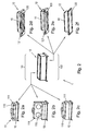
- FIGS. 2a to 2f different fan modules 11 and different feed modules 12 are shown, which can be connected to each other via the central frame 10.
- FIG. 2 In the subfigures 2a to 2c on the left side examples of possible fan modules 11 are shown, which on the top of the central frame 10, in the middle of the FIG. 2 is shown, can be connected via the interface 101. In the FIGS. 2a to 2c the respective fan modules 11 are shown in the attached to the central frame 10 state.
- FIG. 2a is an extremely flat fan module 11, that is, a fan module 11 with low height, with lying fan housings 110 shown in the extractor housing 111.
- the fan wheels provided in the fan housing 110 can be designed either as a single-engine or as a twin-engine variant.
- the extractor housing 111 can be made of either sheet metal or plastic both for the single-engine and for the twin-engine variant. Due to its flat design, it is ideal for use with low wall cabinets or to create more space in the wall cabinet above the extractor hood 1 for shelves.
- FIG. 2b a stepped fan module 11 is shown, which is made higher in the standing fan wheels in the standing fan housing 110 than the flat fan module 11 FIG. 2a ,
- the extractor housing 111 of the fan module 11 is off FIG. 2a however, a rather low level is formed, on which above the level a so-called spice board (spice rack in the cupboard) can be attached.
- the step in this fan module 11, in particular in the extractor housing 111 is due to the better Performance values (air performance and noise levels) very important.
- This fan module 11 can achieve significantly better performance values than the flat fan module 11 FIG. 2a because almost no air deflection has to take place due to the standing fan wheels.
- This fan module 11 may also be configured as single or twin-engine and the extractor housing 111 may be made of plastic or sheet metal, without requiring a variant of the central frame 10, from the variant of the central frame 10 for the fan module 11 FIG. 2a differs.
- FIG 2c is a fan module 11 with double-flow fan, which is usually used in food shown.
- this fan module 11 takes up more space in the wall unit than the fan modules 11 mentioned above, however, better performance values and higher air outputs can be achieved with this fan module 11 due to the fan than with the use of fan wheels. It is also conceivable to design this fan module so that the fan outlet can be variably positioned by the customer with little effort, for example up, to the side, to the rear or to the front. Also for this fan module 11 according to the invention the same central frame 10 as for the fan modules FIGS. 2a and 2b be used.
- each one of the same central frame 10 can be used.
- the central frame 10 can be used to connect the different fan modules 11, if necessary, several connection points (in FIG. 2 not shown), which allow or simplify the connection with the different fan modules 11.
- connection points in FIG. 2 not shown, which allow or simplify the connection with the different fan modules 11.
- the required connection points in the central frame 10 is provided.
- feed modules 12 may be provided on the underside of the central frame 10. These feed modules 12 differ according to the designs and / or the design of the Anströmgeometrie, can enter the hood through the air.
- FIGS. 2d to 2f are three examples of possible gullet modules 12, that is, design variants, shown attached to the underside of the central frame 10 can be.
- the respective infill modules 12 are shown in the condition attached to the center frame 10.
- each illustrated vent module 12 is also represented by the dimensions of the central frame 10 in the desired width, depth and height design. Here, only the outer dimensions of the corresponding flow module 12 are changed.
- a pullout module 12 with extendable umbrella also referred to as a drawer 121
- An extractor hood 1 provided with this module 12 is also referred to as a flat screen hood.
- the operation that is, the controls are mounted in the pull-out drawer 121, in particular in the front of the handle bar, as in the Figure 2d shown.
- the controls can also be provided on the top of the drawer 121 or on the right or left side of the drawer 121.
- the pull-out drawer 121 can be equipped with a filter element 120, with a glass plate (not shown) or as a pure pull-out screen, for example made of sheet metal (not shown).
- the backlight may be stationary, fixed on the side, or extendable in the drawer 121.
- FIG. 2e is another exhaust module 12 with retractable drawer 121, that is shown for a flat screen covers.
- the operation in the fixed part of the wall module 12 may be appropriate, for example, left or right behind the handle in the fixed profile strips / housing parts or on the bottom of the wall module 12 laterally or rearwardly.
- the pull-out drawer can be equipped with the filter element 120, with a glass plate or as a pure pull-out screen, for example made of sheet metal (not shown).
- the lighting can be fixed at the rear, fixed at the side or fixed at the front.
- FIG. 2f a fixed vent module 12 is shown.
- An extractor hood 1 provided with such a vent module 12 can for example be installed as fan components in wall cabinets or country kitchen kitchens or serve as a ceiling fan.
- the flexible width and depth design is even more important because fan blocks and ceiling ventilation in different width and Deep versions are offered on the market.
- a feed module 12 which has the desired dimensions and a specific design and a particular design and which is connected to the central frame 10
- the fan components and ceiling vents can be produced in various embodiments and with a variety of equipment and components.
- the shape of the central frame can deviate from the shape shown, for example, the front wall of the central frame can be recessed. Also on the in the FIG. 1 shown stages can be omitted in an alternative embodiment. It is also possible to provide only one step or more than two steps. Furthermore, differently configured and / or differently positioned connection points than those in the FIG. 1 be provided connection points shown. For example, at least fold can be introduced into the upper edge of the central frame and / or be provided in the side surfaces through-holes, which may for example be recesses or tabs, optionally with openings.
- food may have the structure according to the invention with a central frame.
- a flat fan module see FIG. 2a
- the connection module of such a food-extractor hood then preferably a connection of the telescopic channel, which is also referred to as a fireplace is provided.
- fan modules and vent module that is, design modules
- vent module that is, design modules
- fan modules and vent module can be combined with each other, whereby a high flexibility is achieved.
- Further fan module or modules can be provided, whereby the flexibility is increased.
- the platform concept which is feasible by the present invention. is based on the central frame, which is a central component that serves as a stabilizing element for all cooker hoods.
- the outer dimensions of the central frame are preferably designed so that each cooker hood, which is equipped with the central frame, can be mounted in standard hanging cabinets in any known installation situation.
- the present invention has a number of advantages. In particular, a significant reduction in complexity is achieved. In addition, investment in tools can be saved and due to the common part strategy a significant simplification of the device structure is achieved. Furthermore, development costs are reduced. The assembly of the hood is simplified because uniform, simpler installation processes can be realized. In the development of new cooker hoods, the project times are shorter and the planning and control effort in the factory is lower. In addition, the logistics are simplified, since a smaller number of parts must be provided. Finally, the present invention leads to a significant cost reduction, for example, for material, wages, storage costs and one-off expenses for new products.
Landscapes
- Engineering & Computer Science (AREA)
- Chemical & Material Sciences (AREA)
- Combustion & Propulsion (AREA)
- Mechanical Engineering (AREA)
- General Engineering & Computer Science (AREA)
- Ventilation (AREA)
- Superstructure Of Vehicle (AREA)
- Housing For Livestock And Birds (AREA)
Applications Claiming Priority (1)
| Application Number | Priority Date | Filing Date | Title |
|---|---|---|---|
| DE102013213810.5A DE102013213810A1 (de) | 2013-07-15 | 2013-07-15 | Zentralrahmen für Dunstabzugshaube und Dunstabzugshaube |
Publications (3)
| Publication Number | Publication Date |
|---|---|
| EP2827067A2 true EP2827067A2 (fr) | 2015-01-21 |
| EP2827067A3 EP2827067A3 (fr) | 2015-09-09 |
| EP2827067B1 EP2827067B1 (fr) | 2020-07-08 |
Family
ID=51167728
Family Applications (1)
| Application Number | Title | Priority Date | Filing Date |
|---|---|---|---|
| EP14176484.5A Active EP2827067B1 (fr) | 2013-07-15 | 2014-07-10 | Hotte aspirante |
Country Status (2)
| Country | Link |
|---|---|
| EP (1) | EP2827067B1 (fr) |
| DE (1) | DE102013213810A1 (fr) |
Cited By (2)
| Publication number | Priority date | Publication date | Assignee | Title |
|---|---|---|---|---|
| WO2016187460A1 (fr) * | 2015-05-19 | 2016-11-24 | Sinur Richard R | Hotte à évacuation de cuisinière modulaire |
| WO2022233522A1 (fr) * | 2021-05-04 | 2022-11-10 | Miele & Cie. Kg | Ventilateur à aspiration par le bas et procédé d'assemblage |
Families Citing this family (1)
| Publication number | Priority date | Publication date | Assignee | Title |
|---|---|---|---|---|
| DE102017121504A1 (de) * | 2017-09-15 | 2019-03-21 | Berling Aero IP UG (haftungsbeschränkt) | Dunstabzugshaube mit Befestigungsvorrichtung zum Einbau in einen Hängeschrank |
Family Cites Families (8)
| Publication number | Priority date | Publication date | Assignee | Title |
|---|---|---|---|---|
| DE19838648B4 (de) * | 1998-07-18 | 2004-07-15 | Sirius S.r.l | Dunstabzugshauben-System |
| DE29903104U1 (de) * | 1999-02-20 | 1999-05-12 | Atag Kitchen Group B.V., Ulft | Modulare Dunstabzughaube |
| DE20005154U1 (de) * | 2000-03-15 | 2000-06-08 | Bürcher, Friedrich, 82054 Sauerlach | Dunstabzugshaube |
| DE10118881A1 (de) * | 2001-04-18 | 2002-11-07 | Sino Gmbh | Dunstabzugshaubensystem |
| DE102009028809A1 (de) * | 2009-08-21 | 2011-02-24 | BSH Bosch und Siemens Hausgeräte GmbH | Dunstabzugshaube, Bausatz für Dunstabzugshauben und Verfahren zur Montage einer Dunstabzugshaube |
| DE102009028808A1 (de) * | 2009-08-21 | 2011-02-24 | BSH Bosch und Siemens Hausgeräte GmbH | Innenrahmen für Dunstabzugshaube und Dunstabzugshaube |
| DE102011017685A1 (de) * | 2011-04-28 | 2012-10-31 | BSH Bosch und Siemens Hausgeräte GmbH | Lüftungsanlage |
| DE102012207852A1 (de) * | 2012-05-11 | 2013-11-14 | BSH Bosch und Siemens Hausgeräte GmbH | Zwischenelement für Dunstabzugshaube, insbesondere Esse, und Dunstabzugshaube |
-
2013
- 2013-07-15 DE DE102013213810.5A patent/DE102013213810A1/de not_active Withdrawn
-
2014
- 2014-07-10 EP EP14176484.5A patent/EP2827067B1/fr active Active
Non-Patent Citations (1)
| Title |
|---|
| None |
Cited By (6)
| Publication number | Priority date | Publication date | Assignee | Title |
|---|---|---|---|---|
| WO2016187460A1 (fr) * | 2015-05-19 | 2016-11-24 | Sinur Richard R | Hotte à évacuation de cuisinière modulaire |
| US10378777B2 (en) | 2015-05-19 | 2019-08-13 | Broan-Nutone Llc | Modular range vent hood |
| US10539329B2 (en) | 2015-05-19 | 2020-01-21 | Broan-Nutone Llc | Range hood installation system |
| US11519611B2 (en) | 2015-05-19 | 2022-12-06 | Broan-Nutone Llc | Range hood installation system |
| US12025316B2 (en) | 2015-05-19 | 2024-07-02 | Broan-Nutone Llc | Range hood installation system |
| WO2022233522A1 (fr) * | 2021-05-04 | 2022-11-10 | Miele & Cie. Kg | Ventilateur à aspiration par le bas et procédé d'assemblage |
Also Published As
| Publication number | Publication date |
|---|---|
| EP2827067A3 (fr) | 2015-09-09 |
| EP2827067B1 (fr) | 2020-07-08 |
| DE102013213810A1 (de) | 2015-01-15 |
Similar Documents
| Publication | Publication Date | Title |
|---|---|---|
| EP3775700B1 (fr) | Dispositif d'évacuation de fumée comprenant un dispositif de filtrage | |
| EP3504483A1 (fr) | Appareil combiné et appareil de cuisine comprenant cet appareil combiné | |
| EP3217099A1 (fr) | Hotte aspirante | |
| EP2467647A1 (fr) | Cadre intérieur pour hotte aspirante et hotte aspirante | |
| EP2827067A2 (fr) | Cadre central pour hotte aspirante et hotte aspirante | |
| EP1548368B1 (fr) | Ensemble de hottes de cuisine à tiroirs | |
| EP2467648B1 (fr) | Hotte aspirante et procédé de montage de hotte aspirante | |
| DE102009028807A1 (de) | Dunstabzugshaube | |
| EP2662636A2 (fr) | Elément intermédiaire pour hotte aspirante, notamment cheminée et hotte aspirante | |
| EP2138769B1 (fr) | Écran coulissant pour hotte aspirante et hotte aspirante | |
| DE102015212283B4 (de) | Lüftergehäuse für eine Dunstabzugshaube | |
| EP3029383B1 (fr) | Hotte aspirante | |
| WO2004057238A1 (fr) | Boitier pour une hotte aspirante comportant un caisson de ventilateur aspirant | |
| DE102009001162A1 (de) | Befestigungsvorrichtung für Bedienteil eines Haushaltsgerätes, Haushaltsgerät und Verfahren zum Befestigen eines Bedienteils | |
| EP1441181B1 (fr) | Boîtier pour une hotte d'extraction | |
| DE102009055075A1 (de) | Lüfterkasten für Dunstabzugshaube | |
| DE102009055077A1 (de) | Lüfterkasten für Dunstabzugshaube | |
| EP3801133A1 (fr) | Châssis pour tiroir | |
| DE102015203436A1 (de) | Dunstabzugshaube mit Auszugskörper | |
| DE202014100557U1 (de) | Möbelauszug und Frontblende für einen Möbelauszug | |
| EP2145135A1 (fr) | Parois latérales d'un logement pour hotte aspirante, logement pour hotte aspirante et hotte aspirante correspondante | |
| EP3835663A1 (fr) | Boitier d'appareil pour un appareil combiné, appareil combiné et kit pour le boitier d'appareil | |
| EP2827066A2 (fr) | Dispositif d'élément de commande pour hotte aspirante et hotte aspirante | |
| DE102013200104B4 (de) | Dunstabzugshaube mit Kamin und Geruchsfilter | |
| DE102021200717A1 (de) | Dunstabzugsvorrichtung mit Anschlussvorrichtung und Verfahren zum Anschließen einer Dunstabzugsvorrichtung an einen Luftkanal |
Legal Events
| Date | Code | Title | Description |
|---|---|---|---|
| 17P | Request for examination filed |
Effective date: 20140710 |
|
| AK | Designated contracting states |
Kind code of ref document: A2 Designated state(s): AL AT BE BG CH CY CZ DE DK EE ES FI FR GB GR HR HU IE IS IT LI LT LU LV MC MK MT NL NO PL PT RO RS SE SI SK SM TR |
|
| AX | Request for extension of the european patent |
Extension state: BA ME |
|
| PUAI | Public reference made under article 153(3) epc to a published international application that has entered the european phase |
Free format text: ORIGINAL CODE: 0009012 |
|
| RAP1 | Party data changed (applicant data changed or rights of an application transferred) |
Owner name: BSH HAUSGERAETE GMBH |
|
| PUAL | Search report despatched |
Free format text: ORIGINAL CODE: 0009013 |
|
| AK | Designated contracting states |
Kind code of ref document: A3 Designated state(s): AL AT BE BG CH CY CZ DE DK EE ES FI FR GB GR HR HU IE IS IT LI LT LU LV MC MK MT NL NO PL PT RO RS SE SI SK SM TR |
|
| AX | Request for extension of the european patent |
Extension state: BA ME |
|
| RIC1 | Information provided on ipc code assigned before grant |
Ipc: F24C 15/20 20060101AFI20150805BHEP |
|
| R17P | Request for examination filed (corrected) |
Effective date: 20160309 |
|
| RBV | Designated contracting states (corrected) |
Designated state(s): AL AT BE BG CH CY CZ DE DK EE ES FI FR GB GR HR HU IE IS IT LI LT LU LV MC MK MT NL NO PL PT RO RS SE SI SK SM TR |
|
| STAA | Information on the status of an ep patent application or granted ep patent |
Free format text: STATUS: EXAMINATION IS IN PROGRESS |
|
| 17Q | First examination report despatched |
Effective date: 20161129 |
|
| GRAP | Despatch of communication of intention to grant a patent |
Free format text: ORIGINAL CODE: EPIDOSNIGR1 |
|
| STAA | Information on the status of an ep patent application or granted ep patent |
Free format text: STATUS: GRANT OF PATENT IS INTENDED |
|
| INTG | Intention to grant announced |
Effective date: 20200221 |
|
| GRAS | Grant fee paid |
Free format text: ORIGINAL CODE: EPIDOSNIGR3 |
|
| GRAA | (expected) grant |
Free format text: ORIGINAL CODE: 0009210 |
|
| STAA | Information on the status of an ep patent application or granted ep patent |
Free format text: STATUS: THE PATENT HAS BEEN GRANTED |
|
| AK | Designated contracting states |
Kind code of ref document: B1 Designated state(s): AL AT BE BG CH CY CZ DE DK EE ES FI FR GB GR HR HU IE IS IT LI LT LU LV MC MK MT NL NO PL PT RO RS SE SI SK SM TR |
|
| REG | Reference to a national code |
Ref country code: CH Ref legal event code: EP Ref country code: AT Ref legal event code: REF Ref document number: 1288874 Country of ref document: AT Kind code of ref document: T Effective date: 20200715 |
|
| REG | Reference to a national code |
Ref country code: DE Ref legal event code: R096 Ref document number: 502014014408 Country of ref document: DE |
|
| REG | Reference to a national code |
Ref country code: IE Ref legal event code: FG4D Free format text: LANGUAGE OF EP DOCUMENT: GERMAN |
|
| REG | Reference to a national code |
Ref country code: LT Ref legal event code: MG4D |
|
| REG | Reference to a national code |
Ref country code: NL Ref legal event code: MP Effective date: 20200708 |
|
| PG25 | Lapsed in a contracting state [announced via postgrant information from national office to epo] |
Ref country code: FI Free format text: LAPSE BECAUSE OF FAILURE TO SUBMIT A TRANSLATION OF THE DESCRIPTION OR TO PAY THE FEE WITHIN THE PRESCRIBED TIME-LIMIT Effective date: 20200708 Ref country code: LT Free format text: LAPSE BECAUSE OF FAILURE TO SUBMIT A TRANSLATION OF THE DESCRIPTION OR TO PAY THE FEE WITHIN THE PRESCRIBED TIME-LIMIT Effective date: 20200708 Ref country code: SE Free format text: LAPSE BECAUSE OF FAILURE TO SUBMIT A TRANSLATION OF THE DESCRIPTION OR TO PAY THE FEE WITHIN THE PRESCRIBED TIME-LIMIT Effective date: 20200708 Ref country code: HR Free format text: LAPSE BECAUSE OF FAILURE TO SUBMIT A TRANSLATION OF THE DESCRIPTION OR TO PAY THE FEE WITHIN THE PRESCRIBED TIME-LIMIT Effective date: 20200708 Ref country code: GR Free format text: LAPSE BECAUSE OF FAILURE TO SUBMIT A TRANSLATION OF THE DESCRIPTION OR TO PAY THE FEE WITHIN THE PRESCRIBED TIME-LIMIT Effective date: 20201009 Ref country code: ES Free format text: LAPSE BECAUSE OF FAILURE TO SUBMIT A TRANSLATION OF THE DESCRIPTION OR TO PAY THE FEE WITHIN THE PRESCRIBED TIME-LIMIT Effective date: 20200708 Ref country code: NO Free format text: LAPSE BECAUSE OF FAILURE TO SUBMIT A TRANSLATION OF THE DESCRIPTION OR TO PAY THE FEE WITHIN THE PRESCRIBED TIME-LIMIT Effective date: 20201008 Ref country code: BG Free format text: LAPSE BECAUSE OF FAILURE TO SUBMIT A TRANSLATION OF THE DESCRIPTION OR TO PAY THE FEE WITHIN THE PRESCRIBED TIME-LIMIT Effective date: 20201008 Ref country code: PT Free format text: LAPSE BECAUSE OF FAILURE TO SUBMIT A TRANSLATION OF THE DESCRIPTION OR TO PAY THE FEE WITHIN THE PRESCRIBED TIME-LIMIT Effective date: 20201109 |
|
| PG25 | Lapsed in a contracting state [announced via postgrant information from national office to epo] |
Ref country code: RS Free format text: LAPSE BECAUSE OF FAILURE TO SUBMIT A TRANSLATION OF THE DESCRIPTION OR TO PAY THE FEE WITHIN THE PRESCRIBED TIME-LIMIT Effective date: 20200708 Ref country code: PL Free format text: LAPSE BECAUSE OF FAILURE TO SUBMIT A TRANSLATION OF THE DESCRIPTION OR TO PAY THE FEE WITHIN THE PRESCRIBED TIME-LIMIT Effective date: 20200708 Ref country code: LV Free format text: LAPSE BECAUSE OF FAILURE TO SUBMIT A TRANSLATION OF THE DESCRIPTION OR TO PAY THE FEE WITHIN THE PRESCRIBED TIME-LIMIT Effective date: 20200708 Ref country code: IS Free format text: LAPSE BECAUSE OF FAILURE TO SUBMIT A TRANSLATION OF THE DESCRIPTION OR TO PAY THE FEE WITHIN THE PRESCRIBED TIME-LIMIT Effective date: 20201108 |
|
| REG | Reference to a national code |
Ref country code: CH Ref legal event code: PL |
|
| PG25 | Lapsed in a contracting state [announced via postgrant information from national office to epo] |
Ref country code: NL Free format text: LAPSE BECAUSE OF FAILURE TO SUBMIT A TRANSLATION OF THE DESCRIPTION OR TO PAY THE FEE WITHIN THE PRESCRIBED TIME-LIMIT Effective date: 20200708 |
|
| REG | Reference to a national code |
Ref country code: DE Ref legal event code: R097 Ref document number: 502014014408 Country of ref document: DE |
|
| REG | Reference to a national code |
Ref country code: BE Ref legal event code: MM Effective date: 20200731 |
|
| PG25 | Lapsed in a contracting state [announced via postgrant information from national office to epo] |
Ref country code: MC Free format text: LAPSE BECAUSE OF FAILURE TO SUBMIT A TRANSLATION OF THE DESCRIPTION OR TO PAY THE FEE WITHIN THE PRESCRIBED TIME-LIMIT Effective date: 20200708 Ref country code: LU Free format text: LAPSE BECAUSE OF NON-PAYMENT OF DUE FEES Effective date: 20200710 Ref country code: SM Free format text: LAPSE BECAUSE OF FAILURE TO SUBMIT A TRANSLATION OF THE DESCRIPTION OR TO PAY THE FEE WITHIN THE PRESCRIBED TIME-LIMIT Effective date: 20200708 Ref country code: RO Free format text: LAPSE BECAUSE OF FAILURE TO SUBMIT A TRANSLATION OF THE DESCRIPTION OR TO PAY THE FEE WITHIN THE PRESCRIBED TIME-LIMIT Effective date: 20200708 Ref country code: LI Free format text: LAPSE BECAUSE OF NON-PAYMENT OF DUE FEES Effective date: 20200731 Ref country code: IT Free format text: LAPSE BECAUSE OF FAILURE TO SUBMIT A TRANSLATION OF THE DESCRIPTION OR TO PAY THE FEE WITHIN THE PRESCRIBED TIME-LIMIT Effective date: 20200708 Ref country code: CZ Free format text: LAPSE BECAUSE OF FAILURE TO SUBMIT A TRANSLATION OF THE DESCRIPTION OR TO PAY THE FEE WITHIN THE PRESCRIBED TIME-LIMIT Effective date: 20200708 Ref country code: DK Free format text: LAPSE BECAUSE OF FAILURE TO SUBMIT A TRANSLATION OF THE DESCRIPTION OR TO PAY THE FEE WITHIN THE PRESCRIBED TIME-LIMIT Effective date: 20200708 Ref country code: CH Free format text: LAPSE BECAUSE OF NON-PAYMENT OF DUE FEES Effective date: 20200731 Ref country code: EE Free format text: LAPSE BECAUSE OF FAILURE TO SUBMIT A TRANSLATION OF THE DESCRIPTION OR TO PAY THE FEE WITHIN THE PRESCRIBED TIME-LIMIT Effective date: 20200708 |
|
| PLBE | No opposition filed within time limit |
Free format text: ORIGINAL CODE: 0009261 |
|
| STAA | Information on the status of an ep patent application or granted ep patent |
Free format text: STATUS: NO OPPOSITION FILED WITHIN TIME LIMIT |
|
| PG25 | Lapsed in a contracting state [announced via postgrant information from national office to epo] |
Ref country code: BE Free format text: LAPSE BECAUSE OF NON-PAYMENT OF DUE FEES Effective date: 20200731 Ref country code: AL Free format text: LAPSE BECAUSE OF FAILURE TO SUBMIT A TRANSLATION OF THE DESCRIPTION OR TO PAY THE FEE WITHIN THE PRESCRIBED TIME-LIMIT Effective date: 20200708 |
|
| 26N | No opposition filed |
Effective date: 20210409 |
|
| GBPC | Gb: european patent ceased through non-payment of renewal fee |
Effective date: 20201008 |
|
| PG25 | Lapsed in a contracting state [announced via postgrant information from national office to epo] |
Ref country code: SK Free format text: LAPSE BECAUSE OF FAILURE TO SUBMIT A TRANSLATION OF THE DESCRIPTION OR TO PAY THE FEE WITHIN THE PRESCRIBED TIME-LIMIT Effective date: 20200708 |
|
| PG25 | Lapsed in a contracting state [announced via postgrant information from national office to epo] |
Ref country code: FR Free format text: LAPSE BECAUSE OF NON-PAYMENT OF DUE FEES Effective date: 20200908 |
|
| PG25 | Lapsed in a contracting state [announced via postgrant information from national office to epo] |
Ref country code: GB Free format text: LAPSE BECAUSE OF NON-PAYMENT OF DUE FEES Effective date: 20201008 Ref country code: IE Free format text: LAPSE BECAUSE OF NON-PAYMENT OF DUE FEES Effective date: 20200710 Ref country code: SI Free format text: LAPSE BECAUSE OF FAILURE TO SUBMIT A TRANSLATION OF THE DESCRIPTION OR TO PAY THE FEE WITHIN THE PRESCRIBED TIME-LIMIT Effective date: 20200708 |
|
| REG | Reference to a national code |
Ref country code: AT Ref legal event code: MM01 Ref document number: 1288874 Country of ref document: AT Kind code of ref document: T Effective date: 20200710 |
|
| PG25 | Lapsed in a contracting state [announced via postgrant information from national office to epo] |
Ref country code: AT Free format text: LAPSE BECAUSE OF NON-PAYMENT OF DUE FEES Effective date: 20200710 |
|
| PG25 | Lapsed in a contracting state [announced via postgrant information from national office to epo] |
Ref country code: TR Free format text: LAPSE BECAUSE OF FAILURE TO SUBMIT A TRANSLATION OF THE DESCRIPTION OR TO PAY THE FEE WITHIN THE PRESCRIBED TIME-LIMIT Effective date: 20200708 Ref country code: MT Free format text: LAPSE BECAUSE OF FAILURE TO SUBMIT A TRANSLATION OF THE DESCRIPTION OR TO PAY THE FEE WITHIN THE PRESCRIBED TIME-LIMIT Effective date: 20200708 Ref country code: CY Free format text: LAPSE BECAUSE OF FAILURE TO SUBMIT A TRANSLATION OF THE DESCRIPTION OR TO PAY THE FEE WITHIN THE PRESCRIBED TIME-LIMIT Effective date: 20200708 |
|
| PG25 | Lapsed in a contracting state [announced via postgrant information from national office to epo] |
Ref country code: MK Free format text: LAPSE BECAUSE OF FAILURE TO SUBMIT A TRANSLATION OF THE DESCRIPTION OR TO PAY THE FEE WITHIN THE PRESCRIBED TIME-LIMIT Effective date: 20200708 |
|
| REG | Reference to a national code |
Ref country code: DE Ref legal event code: R084 Ref document number: 502014014408 Country of ref document: DE |
|
| PGFP | Annual fee paid to national office [announced via postgrant information from national office to epo] |
Ref country code: DE Payment date: 20230731 Year of fee payment: 10 |