EP3217099A1 - Hotte aspirante - Google Patents
Hotte aspirante Download PDFInfo
- Publication number
- EP3217099A1 EP3217099A1 EP17156829.8A EP17156829A EP3217099A1 EP 3217099 A1 EP3217099 A1 EP 3217099A1 EP 17156829 A EP17156829 A EP 17156829A EP 3217099 A1 EP3217099 A1 EP 3217099A1
- Authority
- EP
- European Patent Office
- Prior art keywords
- adapter element
- fan box
- extractor hood
- hood according
- hood
- Prior art date
- Legal status (The legal status is an assumption and is not a legal conclusion. Google has not performed a legal analysis and makes no representation as to the accuracy of the status listed.)
- Granted
Links
- 239000002184 metal Substances 0.000 claims description 6
- 239000000725 suspension Substances 0.000 description 35
- 239000000463 material Substances 0.000 description 5
- 238000003780 insertion Methods 0.000 description 3
- 230000037431 insertion Effects 0.000 description 3
- 238000005452 bending Methods 0.000 description 2
- 238000010586 diagram Methods 0.000 description 2
- 230000009191 jumping Effects 0.000 description 2
- 238000004519 manufacturing process Methods 0.000 description 2
- 238000004080 punching Methods 0.000 description 2
- 230000007704 transition Effects 0.000 description 2
- 230000000007 visual effect Effects 0.000 description 2
- OKTJSMMVPCPJKN-UHFFFAOYSA-N Carbon Chemical compound [C] OKTJSMMVPCPJKN-UHFFFAOYSA-N 0.000 description 1
- 229910052799 carbon Inorganic materials 0.000 description 1
- 238000005253 cladding Methods 0.000 description 1
- 238000010276 construction Methods 0.000 description 1
- 238000004049 embossing Methods 0.000 description 1
- 239000011521 glass Substances 0.000 description 1
- 239000004519 grease Substances 0.000 description 1
- 238000012423 maintenance Methods 0.000 description 1
- 238000000034 method Methods 0.000 description 1
- 239000005022 packaging material Substances 0.000 description 1
- 238000003825 pressing Methods 0.000 description 1
- 230000002787 reinforcement Effects 0.000 description 1
- 239000010802 sludge Substances 0.000 description 1
- 239000006228 supernatant Substances 0.000 description 1
- 238000009423 ventilation Methods 0.000 description 1
Images


Classifications
-
- F—MECHANICAL ENGINEERING; LIGHTING; HEATING; WEAPONS; BLASTING
- F24—HEATING; RANGES; VENTILATING
- F24C—DOMESTIC STOVES OR RANGES ; DETAILS OF DOMESTIC STOVES OR RANGES, OF GENERAL APPLICATION
- F24C15/00—Details
- F24C15/20—Removing cooking fumes
- F24C15/2071—Removing cooking fumes mounting of cooking hood
Definitions
- hoods which are also referred to as boxing.
- the fan box in which the fan of the hood is inserted, sits on top of a viewing hood and is covered by a telescopic channel. So that the suspension is easily accessible, this is above the fan box.
- an additional locking screw in the wall is required, which must be screwed from the inside in the lower part of the fan box.
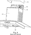
- Such a known extractor hood which represents a boxing, is in FIG. 4 shown. It follows that the eccentric screw elements ES must be introduced through openings in an upper projection ÜS of the rear wall of the fan box LK. In addition, an opening for a security element SE, in particular a locking screw is shown in the lower region of the rear wall of the fan box LK.
- the fan box LK is disguised after assembly of a telescopic channel KA, which is also referred to as a fireplace.
- a generation of extractor hoods in which instead of the box-shaped viewing hood, a sloping viewing hood, which is also referred to as Wrasencept is used is referred to as skew.
- skew a sloping viewing hood
- the invention is therefore an object of the invention to provide a hood with wall mounting device, which allows for a simple and secure attachment of the fan box to the mounting wall and on the other hand allows a good visual appearance of the hood.
- the invention is based on the finding that this object can be achieved by an adapter element is used, which is between the back of the fan box and the room wall to which the hood is to be attached, and is detachably connected to the fan box.
- an extractor hood which has a fan box, which has at least one mounting opening in the back.
- the extractor hood is characterized in that the extractor hood comprises an adapter element which rests with the front on at least a part of the back of the fan box, that the adapter element has a base surface, that at least one attachment projection is arranged on the base, extending from the base extends at least partially forward, and that in the base at least one screw hole is introduced.
- an extractor hood As an extractor hood according to the invention preferably an extractor hood is called, which has a fan box.
- the extractor hood can also be called an Esse.
- the housing As a fan box, the housing is referred to, in which the fan of the hood is included.
- the fan box preferably has a rectangular shape and has at least a back, side walls, a lid and a bottom. These areas of the fan box are preferably designed as walls, for example made of sheet metal.
- the front of the fan box may also be formed as a wall. However, the fan box has an inlet opening on one of the walls.
- the wall in which the inlet opening is formed may optionally be completely omitted.
- the bottom of the fan box may have the inlet opening or be recessed to form the inlet opening.
- the vapor shield is arranged on the underside of the fan box.
- the fan box has at least one fastening opening in the rear wall.
- the attachment opening may, for example, constitute an opening punched into the rear wall of the fan box.
- the attachment opening preferably has a rectangular shape.
- at least two fastening openings are provided in the upper region of the rear wall of the fan box.
- at least one additional attachment opening is provided in the lower region of the rear wall of the fan box.
- the mounting holes are used to attach the fan box to an adapter element.
- the fastening devices serve to hook the fan box to the adapter element.
- the extractor hood according to the invention comprises an adapter element.
- the adapter element is detachably connected to the fan box and serves to attach the hood to a mounting wall.
- the adapter element is first attached to the mounting wall and then the fan box connected to the adapter element.
- the adapter element rests with its front side on at least part of the rear side of the fan box.
- a flat, planar element is preferably referred to, which may represent a sheet, for example.
- the adapter element has a base. With the back of the base, the adapter element is in the mounted on the mounting wall state, preferably on the mounting wall. At least one attachment projection is arranged on the base surface.
- the suspension projection extends at least partially from the base to the front.
- the suspension projection is used to engage with the mounting hole on the fan box.
- a hanging projection Lugs, arms, hooks and the like can be used.
- In the base area at least one screw hole is further introduced.
- the screw hole serves to pass through a fastening means, in particular a screw, by means of which the adapter element is fastened to the mounting wall.
- an adapter element is provided in the extractor hood according to the invention, which is releasably connected to the fan box and can also be attached to the mounting wall, the assembly of the hood is simplified on the mounting wall.
- the adapter element can be screwed to the mounting wall via the at least one screw hole. Since the fan box is detachably connected to the adapter element, this screwing the adapter element can be done on the mounting wall, when the fan box is not yet connected to the adapter element. Subsequently, the hood can be hung on the fan box on the adapter element and thus secured and is mounted on the mounting wall.
- the height of the adapter element is equal to or smaller than the distance between the lid, that is top, and bottom, that is bottom, of the fan box. If the bottom is recessed on the fan box and a vapor shield is provided on the underside of the fan box, the height of the adapter element in this embodiment is smaller than the distance between the lid and the bottom of the fan box.
- the width of the adapter element is preferably smaller than the width of the fan box.
- the adapter element is made of sheet metal and the at least one suspension projection represents a tab and / or an arm.
- the suspension projections can be formed by stamping, punching and / or bending from the sheet metal.
- the suspension projections thus, in one piece with the base, the stability and thus the maintenance of the hood are also improved.
- differently shaped attachment projections are provided on the adapter element.
- a tab can be provided in the lower region of the adapter element and two suspension projections designed as arms in the upper region.
- a tab is understood to be a strip of material which projects forward at an angle to the base surface and extends straight.
- An arm is referred to as a strip of material which, at a first angle to the base surface, protrudes forwards towards it and continues in a part which lies at a second angle to the base surface.
- the tab or the arm can be made by punching and bending in an adapter element made of a sheet metal.
- At least one attachment projection is a tab which extends obliquely upward from the base surface.
- the tab may be at an angle in the range of 20 ° to 45 °.
- At least one suspension projection is an upwardly directed arm, which is offset in the region of the free end to the base of the adapter element to the front.
- the region of the free end of the suspension projection is parallel to the base surface.
- the transition from the region lying offset to the base area to the base surface is preferably formed by an area of the arm inclined upward from the base surface. Due to the inclination, an automatic movement of the fan box on the base can be realized when the arm is inserted into a mounting opening of the fan box.
- the embodiment of the suspension device as an arm has the advantage that the area of the suspension device, which is preferably offset in parallel to the base area, is suitable for absorbing weight. The arm can therefore be used at its free end for supporting the fan box from the inside.
- the arm can also serve to secure against unhooking the fan box.
- the arm has a length which is less than the distance of the upper edge of an upper attachment opening to the lid of the fan box.
- the fan box is thus not upon insertion of the arm in the mounting hole on the arm, but the arm extends to just below the lid. If, in this embodiment, a locking screw is guided through the cover and a fastening web on the arm, the fan box is pressed firmly against the adapter element and thus against the mounting wall. This pressing against the adapter element and the mounting wall is aided in that the suspension projections are preferably inclined, for example, represent inclined tabs or arms with an inclined transition region.
- At least one fastening web is provided on at least one suspension projection of the adapter element.
- the fastening web is provided in particular at the free upper end of the suspension projection.
- the fastening web protrudes at the upper edge of the suspension projection from the suspension projection to the front and is located in the mounted state of the hood on the inside of the lid of the fan box.
- a connection surface is created, on the one hand, the support of the fan box is supported on the suspension device.
- the attachment web additionally serves to rest the upper edge of the attachment opening on the attachment projection in order to improve the hold of the ventilation box on the adapter element.
- the fastening web a screw opening can be introduced, via which the fan box can be screwed from above through the lid of the fan box with the suspension device. Since the fastening web rests on the inside of the underside of the lid of the fan box, the locking screw is preferably screwed from above through a screw opening provided in the cover and the fastening web and thus connects the fastening web with the cover.
- the attachment web may be provided on a suspension device which constitutes a tab or on a suspension device which constitutes an arm.
- the at least one screw hole is arranged in the base area adjacent to the at least one attachment projection.
- fastening means in particular screws, which are guided by the screw holes and fasten the adapter element to the mounting wall.
- a screw hole is arranged adjacent to each suspension projection.
- At least one of the screw holes is a slot.
- the slot can be aligned vertically or horizontally. Particularly preferably, at least one slot is horizontal and at least one slot vertically aligned.
- the screw holes represent slots, the adapter element can be easily aligned when mounted on the mounting wall.
- three suspension projections are provided on the adapter element, wherein two arms are provided in the upper region of the adapter element and a tab is provided in the lower region of the adapter element.
- the arms can be used for hanging and in addition to supporting the fan box from the inside up.
- the hanging projection at the bottom of a tab the mounting of the hood is further simplified, since the tab can be easily inserted into the mounting hole of the fan box.
- the extractor hood is a bevel or vertical Esse, which is also referred to as Flat-Esse, represents.
- the fan box In the Schrägesse the fan box is open to the front and the WrasenT is mounted inclined to the front.
- the suction opening of the extractor hood lies vertically, ie parallel to the mounting wall, on the front side of the extractor hood.
- the advantages of the present invention can be used particularly since usually no cladding, such as a chimney is provided around the fan box and a connected only at the back of the fan box adapter element is not visible in the extractor hood according to the invention.
- the embodiment of the hood 1 in FIG. 1 represents a Schrägesse.
- the hood 1 includes a fan box 10, an adapter element 12 (see FIG. 2 ) and a vapor shield 11.
- the fan box 10 has in the illustrated embodiment, a back 100, a lid 101 and a bottom 102. Furthermore, the fan box 10 includes side walls, which are not shown for better visibility of the interior of the fan box 10.
- a fan 13 is accommodated, the outlet nozzle 130 protrudes through the lid 101 of the fan box 10.
- the vapor shield 11 is mounted inclined forward on the front of the fan box 10. In the illustrated embodiment, the vapor shield 11 is configured with a baffle plate 110 in the intake opening of the extractor hood 1.
- mounting holes 1000 are introduced, of which in FIG. 1 only one can be seen in the upper area and one in the lower area of the rear wall 100.
- the mounting holes 1000 have a rectangular shape.
- Hanging devices 121, 126 of an adapter element 12 engage through the attachment openings 1000.
- the adapter element 12 is in FIG. 2 shown in more detail.
- the adapter element 12 has a base area 120 which, in the illustrated embodiment, widens upwards from a narrow strip as a lower area and ends in a wider upper area.
- Attachment devices 121, 126 are formed on the adapter element 12.
- the suspension devices 121, 126 are arranged on the base surface 120 and protrude from the base 120 to the front.
- a tab 121 is provided as a suspension device in the lower region of the adapter element 12.
- the tab 121 represents a piece of material made of the material of the base 120 of the adapter element 12 and is bent forward out of the base 120.
- the tab 121 is inclined upwards.
- a screw hole 122 is inserted into the base 120.
- the screw hole 122 forms a horizontally extending slot. Through this screw hole 122 a mounting screw 124 can be passed and the adapter element 12 thereby on a mounting wall 2 (see FIG. 3 ) are attached.
- two further Ein theoryvorsprünge are provided which are formed as arms 126.
- the arms 126 are offset with their upper portion to the base 120 forward and are in this area parallel to the base 120.
- a fastening web 123 is provided in each case. This extends from the arm 126 to the front and lies in the horizontal.
- a screw hole 122 is provided in each case. These screw holes 122 are formed in the illustrated embodiment by vertically extending slots.
- FIG. 3 is a schematic diagram of the hood 1 shown according to an embodiment of the present invention, based on which now the assembly of the hood 1 should be described again.
- the adapter element 12 is screwed to the mounting wall 2. This is schematically illustrated by the mounting screw 124 in the lower portion of the adapter element in FIG FIG. 3 shown.
- the adapter element 12 but also by other mounting screws 124 (see FIG. 2 ) in the upper area (in FIG. 3 not shown) attached to the mounting wall 2.
- the suspension projections 121, 126 project forward beyond the base surface 120 of the adapter element 12 and the rear side of the base surface 120 bears against the mounting wall 2.
- the fan box 10 of the extractor hood 1 can now be attached to the adapter element 12 mounted in this way.
- the fastening openings 1000 in the rear wall 100 of the fan box 10 are aligned with the suspension projections 121, 126.
- the fan box 10 moved toward the adapter element 12.
- the suspension projections 121, 126 engage with the fastening openings 1000, that is, are inserted into them. Due to its own weight, the fan box 10 then slides downwards along the upper sides of the suspension projections 121, 126, until the rear side of the fan box 10 bears against the front side of the adapter element 12, in particular the base surface 120.
- the insertion projection formed as a tab 121 protrudes obliquely upward into the interior of the fan box 10.
- the vertically extending upper portion of the arm 126 preferably lies against the rear wall 100 of the fan box 10 from the inside.
- the horizontally extending fastening web 123 rests from the inside on the cover 101 of the fan box 10.
- the fastening web 123 is arranged on the upper edge of the suspension projection designed as an arm 126 and protrudes from the arm 126 to the front.
- the arm 126 and in particular the fastening web 123 thus support the fan box 10 in addition.
- the adapter element 12 is thus detachably connected to the fan box 10.
- a locking screw 125 through the lid 101 of the fan box 10 and provided in the fastening web 123 screw opening 1230 (see FIG. 2 ) and the arm 126 is bolted to the fan box 10.
- the present invention thus provides a simple yet reliable way of attaching a cooker hood to a mounting wall, also referred to as a room wall.
- a mounting wall also referred to as a room wall.
- an adapter element which is a sheet metal and therefore can also be referred to as an adapter plate or suspension plate, to the Screwed room wall, aligned and then the hood is hung from it.
- the fan box is secured against levers.
- the mounting screws sit as close to the Einticianvorsprüngen, in particular a tab and two arms to ensure the most stable possible seating of the fan box on the wall.
- An advantage of the present invention is that it is possible due to the mounting method, the adapter element to be dimensioned so that is no longer visible from the parts for wall mounting after attaching the hood.
- the handy adapter element which is preferably a suspension plate, is easy to handle and align when screwed to the mounting wall.
- the mounting screws are still easily accessible to the user.
- the entire extractor hood no longer has to be aligned with adjusting screws or with eccentrically rotating plastic cylinders, as is the case in the prior art.
- the accessibility to a lower locking screw which is required in the prior art, no longer be considered.
- Securing the extractor hood against prying done according to the invention preferably not by the spatially very close screwing the hood directly to the wall but by two easily accessible locking screws that can be screwed from above through the lid of the fan box in the suspension plate.
Landscapes
- Engineering & Computer Science (AREA)
- Chemical & Material Sciences (AREA)
- Combustion & Propulsion (AREA)
- Mechanical Engineering (AREA)
- General Engineering & Computer Science (AREA)
- Ventilation (AREA)
Applications Claiming Priority (1)
| Application Number | Priority Date | Filing Date | Title |
|---|---|---|---|
| DE102016203750.1A DE102016203750A1 (de) | 2016-03-08 | 2016-03-08 | Dunstabzugshaube |
Publications (2)
| Publication Number | Publication Date |
|---|---|
| EP3217099A1 true EP3217099A1 (fr) | 2017-09-13 |
| EP3217099B1 EP3217099B1 (fr) | 2019-04-17 |
Family
ID=58094287
Family Applications (1)
| Application Number | Title | Priority Date | Filing Date |
|---|---|---|---|
| EP17156829.8A Active EP3217099B1 (fr) | 2016-03-08 | 2017-02-20 | Hotte aspirante |
Country Status (2)
| Country | Link |
|---|---|
| EP (1) | EP3217099B1 (fr) |
| DE (1) | DE102016203750A1 (fr) |
Cited By (3)
| Publication number | Priority date | Publication date | Assignee | Title |
|---|---|---|---|---|
| CN111006263A (zh) * | 2020-01-03 | 2020-04-14 | 宁波方太厨具有限公司 | 一种装饰罩安装装置及应用有该安装装置的吸油烟机 |
| CN111434992A (zh) * | 2019-01-11 | 2020-07-21 | 宁波方太厨具有限公司 | 油烟机装饰罩安装结构 |
| US20210348771A1 (en) * | 2018-09-27 | 2021-11-11 | Elica S.P.A. | Systems for mounting kitchen extractor hoods and methods for executing the mounting |
Families Citing this family (5)
| Publication number | Priority date | Publication date | Assignee | Title |
|---|---|---|---|---|
| CN111006264B (zh) * | 2020-01-03 | 2021-10-08 | 宁波方太厨具有限公司 | 一种装饰罩安装装置及应用有该安装装置的吸油烟机 |
| CN111006266B (zh) * | 2020-01-03 | 2021-08-20 | 宁波方太厨具有限公司 | 一种装饰罩安装装置及应用有该安装装置的吸油烟机 |
| CN111006265B (zh) * | 2020-01-03 | 2021-08-20 | 宁波方太厨具有限公司 | 一种装饰罩安装装置及应用有该安装装置的吸油烟机 |
| CN111006268B (zh) * | 2020-01-03 | 2021-08-20 | 宁波方太厨具有限公司 | 一种装饰罩安装装置及应用有该安装装置的吸油烟机 |
| CN111006267B (zh) * | 2020-01-03 | 2021-10-01 | 宁波方太厨具有限公司 | 一种装饰罩安装装置及应用有该安装装置的吸油烟机 |
Citations (3)
| Publication number | Priority date | Publication date | Assignee | Title |
|---|---|---|---|---|
| EP2119970A2 (fr) * | 2008-05-13 | 2009-11-18 | BSH Bosch und Siemens Hausgeräte GmbH | Système de montage destiné au montage d'un boîtier de hotte aspirante pouvant être fixé sur un mur ainsi que procédé de fixation d'un boîtier correspondant |
| DE102011051104B3 (de) * | 2011-06-16 | 2012-11-22 | Miele & Cie. Kg | Dunstabzugshaube für einen Herd, eine Kochstelle oder dergleichen |
| DE102012016630A1 (de) * | 2012-08-22 | 2014-02-27 | Exklusiv-Hauben Gutmann Gmbh | Dunstabzugshaube |
-
2016
- 2016-03-08 DE DE102016203750.1A patent/DE102016203750A1/de not_active Withdrawn
-
2017
- 2017-02-20 EP EP17156829.8A patent/EP3217099B1/fr active Active
Patent Citations (3)
| Publication number | Priority date | Publication date | Assignee | Title |
|---|---|---|---|---|
| EP2119970A2 (fr) * | 2008-05-13 | 2009-11-18 | BSH Bosch und Siemens Hausgeräte GmbH | Système de montage destiné au montage d'un boîtier de hotte aspirante pouvant être fixé sur un mur ainsi que procédé de fixation d'un boîtier correspondant |
| DE102011051104B3 (de) * | 2011-06-16 | 2012-11-22 | Miele & Cie. Kg | Dunstabzugshaube für einen Herd, eine Kochstelle oder dergleichen |
| DE102012016630A1 (de) * | 2012-08-22 | 2014-02-27 | Exklusiv-Hauben Gutmann Gmbh | Dunstabzugshaube |
Cited By (4)
| Publication number | Priority date | Publication date | Assignee | Title |
|---|---|---|---|---|
| US20210348771A1 (en) * | 2018-09-27 | 2021-11-11 | Elica S.P.A. | Systems for mounting kitchen extractor hoods and methods for executing the mounting |
| US11767986B2 (en) * | 2018-09-27 | 2023-09-26 | Elica S.P.A. | Systems for mounting kitchen extractor hoods and methods for executing the mounting |
| CN111434992A (zh) * | 2019-01-11 | 2020-07-21 | 宁波方太厨具有限公司 | 油烟机装饰罩安装结构 |
| CN111006263A (zh) * | 2020-01-03 | 2020-04-14 | 宁波方太厨具有限公司 | 一种装饰罩安装装置及应用有该安装装置的吸油烟机 |
Also Published As
| Publication number | Publication date |
|---|---|
| DE102016203750A1 (de) | 2017-09-14 |
| EP3217099B1 (fr) | 2019-04-17 |
Similar Documents
| Publication | Publication Date | Title |
|---|---|---|
| EP3217099B1 (fr) | Hotte aspirante | |
| EP2467647A1 (fr) | Cadre intérieur pour hotte aspirante et hotte aspirante | |
| EP2467649B1 (fr) | Hotte aspirante | |
| EP2354698A2 (fr) | Grille d'aération pour intégration murale extérieure | |
| EP2159492A2 (fr) | Dispositif de verrouillage pour un élément plan d'une hotte d'aspiration | |
| EP2662636A2 (fr) | Elément intermédiaire pour hotte aspirante, notamment cheminée et hotte aspirante | |
| DE102008024324A1 (de) | Dunstabzugsvorrichtung sowie Verfahren zur Montage einer Dunstabzugsvorrichtung | |
| EP2378209B1 (fr) | Hotte aspirante | |
| EP3244131B1 (fr) | Hotte aspirante comprenant un élément extractible | |
| DE202015100485U1 (de) | Bausatz für den Einbau eines Positionierungsrahmens in einen Möbelauszug | |
| EP2827067A2 (fr) | Cadre central pour hotte aspirante et hotte aspirante | |
| EP3564589B1 (fr) | Dispositif d'aération | |
| DE102015212283B4 (de) | Lüftergehäuse für eine Dunstabzugshaube | |
| EP0962709A2 (fr) | Armoire d'un appareil ménager | |
| DE102015203436B4 (de) | Dunstabzugshaube mit Auszugskörper | |
| WO2011085864A1 (fr) | Tiroir à ventilateur pour hotte aspirante | |
| DE102009055077A1 (de) | Lüfterkasten für Dunstabzugshaube | |
| DE102009001162A1 (de) | Befestigungsvorrichtung für Bedienteil eines Haushaltsgerätes, Haushaltsgerät und Verfahren zum Befestigen eines Bedienteils | |
| EP2145135B1 (fr) | Parois latérales d'un logement pour hotte aspirante, logement pour hotte aspirante et hotte aspirante correspondante | |
| EP2827066B1 (fr) | Hotte aspirante | |
| EP1441181B1 (fr) | Boîtier pour une hotte d'extraction | |
| EP3666120B1 (fr) | Dispositif de raccordement de l'avant de tiroir et tiroir | |
| EP2093501A2 (fr) | Dispositif d'aspiration de vapeur | |
| DE3536711C2 (fr) | ||
| DE102015201368A1 (de) | Dunstabzugshaube mit Verblendungsteil |
Legal Events
| Date | Code | Title | Description |
|---|---|---|---|
| PUAI | Public reference made under article 153(3) epc to a published international application that has entered the european phase |
Free format text: ORIGINAL CODE: 0009012 |
|
| STAA | Information on the status of an ep patent application or granted ep patent |
Free format text: STATUS: THE APPLICATION HAS BEEN PUBLISHED |
|
| AK | Designated contracting states |
Kind code of ref document: A1 Designated state(s): AL AT BE BG CH CY CZ DE DK EE ES FI FR GB GR HR HU IE IS IT LI LT LU LV MC MK MT NL NO PL PT RO RS SE SI SK SM TR |
|
| AX | Request for extension of the european patent |
Extension state: BA ME |
|
| STAA | Information on the status of an ep patent application or granted ep patent |
Free format text: STATUS: REQUEST FOR EXAMINATION WAS MADE |
|
| 17P | Request for examination filed |
Effective date: 20180313 |
|
| RBV | Designated contracting states (corrected) |
Designated state(s): AL AT BE BG CH CY CZ DE DK EE ES FI FR GB GR HR HU IE IS IT LI LT LU LV MC MK MT NL NO PL PT RO RS SE SI SK SM TR |
|
| GRAP | Despatch of communication of intention to grant a patent |
Free format text: ORIGINAL CODE: EPIDOSNIGR1 |
|
| STAA | Information on the status of an ep patent application or granted ep patent |
Free format text: STATUS: GRANT OF PATENT IS INTENDED |
|
| INTG | Intention to grant announced |
Effective date: 20181105 |
|
| GRAS | Grant fee paid |
Free format text: ORIGINAL CODE: EPIDOSNIGR3 |
|
| GRAA | (expected) grant |
Free format text: ORIGINAL CODE: 0009210 |
|
| STAA | Information on the status of an ep patent application or granted ep patent |
Free format text: STATUS: THE PATENT HAS BEEN GRANTED |
|
| AK | Designated contracting states |
Kind code of ref document: B1 Designated state(s): AL AT BE BG CH CY CZ DE DK EE ES FI FR GB GR HR HU IE IS IT LI LT LU LV MC MK MT NL NO PL PT RO RS SE SI SK SM TR |
|
| REG | Reference to a national code |
Ref country code: GB Ref legal event code: FG4D Free format text: NOT ENGLISH |
|
| REG | Reference to a national code |
Ref country code: CH Ref legal event code: EP |
|
| REG | Reference to a national code |
Ref country code: DE Ref legal event code: R096 Ref document number: 502017001118 Country of ref document: DE |
|
| REG | Reference to a national code |
Ref country code: AT Ref legal event code: REF Ref document number: 1121963 Country of ref document: AT Kind code of ref document: T Effective date: 20190515 Ref country code: IE Ref legal event code: FG4D Free format text: LANGUAGE OF EP DOCUMENT: GERMAN |
|
| REG | Reference to a national code |
Ref country code: NL Ref legal event code: MP Effective date: 20190417 |
|
| REG | Reference to a national code |
Ref country code: LT Ref legal event code: MG4D |
|
| PG25 | Lapsed in a contracting state [announced via postgrant information from national office to epo] |
Ref country code: NL Free format text: LAPSE BECAUSE OF FAILURE TO SUBMIT A TRANSLATION OF THE DESCRIPTION OR TO PAY THE FEE WITHIN THE PRESCRIBED TIME-LIMIT Effective date: 20190417 |
|
| PG25 | Lapsed in a contracting state [announced via postgrant information from national office to epo] |
Ref country code: ES Free format text: LAPSE BECAUSE OF FAILURE TO SUBMIT A TRANSLATION OF THE DESCRIPTION OR TO PAY THE FEE WITHIN THE PRESCRIBED TIME-LIMIT Effective date: 20190417 Ref country code: PT Free format text: LAPSE BECAUSE OF FAILURE TO SUBMIT A TRANSLATION OF THE DESCRIPTION OR TO PAY THE FEE WITHIN THE PRESCRIBED TIME-LIMIT Effective date: 20190817 Ref country code: AL Free format text: LAPSE BECAUSE OF FAILURE TO SUBMIT A TRANSLATION OF THE DESCRIPTION OR TO PAY THE FEE WITHIN THE PRESCRIBED TIME-LIMIT Effective date: 20190417 Ref country code: SE Free format text: LAPSE BECAUSE OF FAILURE TO SUBMIT A TRANSLATION OF THE DESCRIPTION OR TO PAY THE FEE WITHIN THE PRESCRIBED TIME-LIMIT Effective date: 20190417 Ref country code: HR Free format text: LAPSE BECAUSE OF FAILURE TO SUBMIT A TRANSLATION OF THE DESCRIPTION OR TO PAY THE FEE WITHIN THE PRESCRIBED TIME-LIMIT Effective date: 20190417 Ref country code: LT Free format text: LAPSE BECAUSE OF FAILURE TO SUBMIT A TRANSLATION OF THE DESCRIPTION OR TO PAY THE FEE WITHIN THE PRESCRIBED TIME-LIMIT Effective date: 20190417 Ref country code: FI Free format text: LAPSE BECAUSE OF FAILURE TO SUBMIT A TRANSLATION OF THE DESCRIPTION OR TO PAY THE FEE WITHIN THE PRESCRIBED TIME-LIMIT Effective date: 20190417 Ref country code: NO Free format text: LAPSE BECAUSE OF FAILURE TO SUBMIT A TRANSLATION OF THE DESCRIPTION OR TO PAY THE FEE WITHIN THE PRESCRIBED TIME-LIMIT Effective date: 20190717 |
|
| PG25 | Lapsed in a contracting state [announced via postgrant information from national office to epo] |
Ref country code: LV Free format text: LAPSE BECAUSE OF FAILURE TO SUBMIT A TRANSLATION OF THE DESCRIPTION OR TO PAY THE FEE WITHIN THE PRESCRIBED TIME-LIMIT Effective date: 20190417 Ref country code: RS Free format text: LAPSE BECAUSE OF FAILURE TO SUBMIT A TRANSLATION OF THE DESCRIPTION OR TO PAY THE FEE WITHIN THE PRESCRIBED TIME-LIMIT Effective date: 20190417 Ref country code: PL Free format text: LAPSE BECAUSE OF FAILURE TO SUBMIT A TRANSLATION OF THE DESCRIPTION OR TO PAY THE FEE WITHIN THE PRESCRIBED TIME-LIMIT Effective date: 20190417 Ref country code: GR Free format text: LAPSE BECAUSE OF FAILURE TO SUBMIT A TRANSLATION OF THE DESCRIPTION OR TO PAY THE FEE WITHIN THE PRESCRIBED TIME-LIMIT Effective date: 20190718 Ref country code: BG Free format text: LAPSE BECAUSE OF FAILURE TO SUBMIT A TRANSLATION OF THE DESCRIPTION OR TO PAY THE FEE WITHIN THE PRESCRIBED TIME-LIMIT Effective date: 20190717 |
|
| PG25 | Lapsed in a contracting state [announced via postgrant information from national office to epo] |
Ref country code: IS Free format text: LAPSE BECAUSE OF FAILURE TO SUBMIT A TRANSLATION OF THE DESCRIPTION OR TO PAY THE FEE WITHIN THE PRESCRIBED TIME-LIMIT Effective date: 20190817 |
|
| REG | Reference to a national code |
Ref country code: DE Ref legal event code: R097 Ref document number: 502017001118 Country of ref document: DE |
|
| PG25 | Lapsed in a contracting state [announced via postgrant information from national office to epo] |
Ref country code: DK Free format text: LAPSE BECAUSE OF FAILURE TO SUBMIT A TRANSLATION OF THE DESCRIPTION OR TO PAY THE FEE WITHIN THE PRESCRIBED TIME-LIMIT Effective date: 20190417 Ref country code: SK Free format text: LAPSE BECAUSE OF FAILURE TO SUBMIT A TRANSLATION OF THE DESCRIPTION OR TO PAY THE FEE WITHIN THE PRESCRIBED TIME-LIMIT Effective date: 20190417 Ref country code: EE Free format text: LAPSE BECAUSE OF FAILURE TO SUBMIT A TRANSLATION OF THE DESCRIPTION OR TO PAY THE FEE WITHIN THE PRESCRIBED TIME-LIMIT Effective date: 20190417 Ref country code: CZ Free format text: LAPSE BECAUSE OF FAILURE TO SUBMIT A TRANSLATION OF THE DESCRIPTION OR TO PAY THE FEE WITHIN THE PRESCRIBED TIME-LIMIT Effective date: 20190417 Ref country code: RO Free format text: LAPSE BECAUSE OF FAILURE TO SUBMIT A TRANSLATION OF THE DESCRIPTION OR TO PAY THE FEE WITHIN THE PRESCRIBED TIME-LIMIT Effective date: 20190417 |
|
| PLBE | No opposition filed within time limit |
Free format text: ORIGINAL CODE: 0009261 |
|
| STAA | Information on the status of an ep patent application or granted ep patent |
Free format text: STATUS: NO OPPOSITION FILED WITHIN TIME LIMIT |
|
| PG25 | Lapsed in a contracting state [announced via postgrant information from national office to epo] |
Ref country code: SM Free format text: LAPSE BECAUSE OF FAILURE TO SUBMIT A TRANSLATION OF THE DESCRIPTION OR TO PAY THE FEE WITHIN THE PRESCRIBED TIME-LIMIT Effective date: 20190417 Ref country code: IT Free format text: LAPSE BECAUSE OF FAILURE TO SUBMIT A TRANSLATION OF THE DESCRIPTION OR TO PAY THE FEE WITHIN THE PRESCRIBED TIME-LIMIT Effective date: 20190417 |
|
| 26N | No opposition filed |
Effective date: 20200120 |
|
| PG25 | Lapsed in a contracting state [announced via postgrant information from national office to epo] |
Ref country code: TR Free format text: LAPSE BECAUSE OF FAILURE TO SUBMIT A TRANSLATION OF THE DESCRIPTION OR TO PAY THE FEE WITHIN THE PRESCRIBED TIME-LIMIT Effective date: 20190417 |
|
| PG25 | Lapsed in a contracting state [announced via postgrant information from national office to epo] |
Ref country code: SI Free format text: LAPSE BECAUSE OF FAILURE TO SUBMIT A TRANSLATION OF THE DESCRIPTION OR TO PAY THE FEE WITHIN THE PRESCRIBED TIME-LIMIT Effective date: 20190417 |
|
| REG | Reference to a national code |
Ref country code: CH Ref legal event code: PL |
|
| REG | Reference to a national code |
Ref country code: BE Ref legal event code: MM Effective date: 20200229 |
|
| PG25 | Lapsed in a contracting state [announced via postgrant information from national office to epo] |
Ref country code: LU Free format text: LAPSE BECAUSE OF NON-PAYMENT OF DUE FEES Effective date: 20200220 Ref country code: MC Free format text: LAPSE BECAUSE OF FAILURE TO SUBMIT A TRANSLATION OF THE DESCRIPTION OR TO PAY THE FEE WITHIN THE PRESCRIBED TIME-LIMIT Effective date: 20190417 |
|
| PG25 | Lapsed in a contracting state [announced via postgrant information from national office to epo] |
Ref country code: CH Free format text: LAPSE BECAUSE OF NON-PAYMENT OF DUE FEES Effective date: 20200229 Ref country code: LI Free format text: LAPSE BECAUSE OF NON-PAYMENT OF DUE FEES Effective date: 20200229 |
|
| PG25 | Lapsed in a contracting state [announced via postgrant information from national office to epo] |
Ref country code: FR Free format text: LAPSE BECAUSE OF NON-PAYMENT OF DUE FEES Effective date: 20200229 Ref country code: IE Free format text: LAPSE BECAUSE OF NON-PAYMENT OF DUE FEES Effective date: 20200220 |
|
| PG25 | Lapsed in a contracting state [announced via postgrant information from national office to epo] |
Ref country code: BE Free format text: LAPSE BECAUSE OF NON-PAYMENT OF DUE FEES Effective date: 20200229 |
|
| GBPC | Gb: european patent ceased through non-payment of renewal fee |
Effective date: 20210220 |
|
| PG25 | Lapsed in a contracting state [announced via postgrant information from national office to epo] |
Ref country code: GB Free format text: LAPSE BECAUSE OF NON-PAYMENT OF DUE FEES Effective date: 20210220 |
|
| PG25 | Lapsed in a contracting state [announced via postgrant information from national office to epo] |
Ref country code: MT Free format text: LAPSE BECAUSE OF FAILURE TO SUBMIT A TRANSLATION OF THE DESCRIPTION OR TO PAY THE FEE WITHIN THE PRESCRIBED TIME-LIMIT Effective date: 20190417 Ref country code: CY Free format text: LAPSE BECAUSE OF FAILURE TO SUBMIT A TRANSLATION OF THE DESCRIPTION OR TO PAY THE FEE WITHIN THE PRESCRIBED TIME-LIMIT Effective date: 20190417 |
|
| PG25 | Lapsed in a contracting state [announced via postgrant information from national office to epo] |
Ref country code: MK Free format text: LAPSE BECAUSE OF FAILURE TO SUBMIT A TRANSLATION OF THE DESCRIPTION OR TO PAY THE FEE WITHIN THE PRESCRIBED TIME-LIMIT Effective date: 20190417 |
|
| REG | Reference to a national code |
Ref country code: AT Ref legal event code: MM01 Ref document number: 1121963 Country of ref document: AT Kind code of ref document: T Effective date: 20220220 |
|
| PG25 | Lapsed in a contracting state [announced via postgrant information from national office to epo] |
Ref country code: AT Free format text: LAPSE BECAUSE OF NON-PAYMENT OF DUE FEES Effective date: 20220220 |
|
| PGFP | Annual fee paid to national office [announced via postgrant information from national office to epo] |
Ref country code: DE Payment date: 20240229 Year of fee payment: 8 |