EP2145135B1 - Parois latérales d'un logement pour hotte aspirante, logement pour hotte aspirante et hotte aspirante correspondante - Google Patents
Parois latérales d'un logement pour hotte aspirante, logement pour hotte aspirante et hotte aspirante correspondante Download PDFInfo
- Publication number
- EP2145135B1 EP2145135B1 EP08736422.0A EP08736422A EP2145135B1 EP 2145135 B1 EP2145135 B1 EP 2145135B1 EP 08736422 A EP08736422 A EP 08736422A EP 2145135 B1 EP2145135 B1 EP 2145135B1
- Authority
- EP
- European Patent Office
- Prior art keywords
- side wall
- side walls
- latching
- range hood
- hood housing
- Prior art date
- Legal status (The legal status is an assumption and is not a legal conclusion. Google has not performed a legal analysis and makes no representation as to the accuracy of the status listed.)
- Active
Links
Images


Classifications
-
- F—MECHANICAL ENGINEERING; LIGHTING; HEATING; WEAPONS; BLASTING
- F24—HEATING; RANGES; VENTILATING
- F24C—DOMESTIC STOVES OR RANGES ; DETAILS OF DOMESTIC STOVES OR RANGES, OF GENERAL APPLICATION
- F24C15/00—Details
- F24C15/20—Removing cooking fumes
- F24C15/2071—Removing cooking fumes mounting of cooking hood
Definitions
- the invention relates to side walls of a fume hood housing an extractor hood, wherein the side walls form a hollow profile in the assembled state. Furthermore, the invention relates to a fume hood housing with side walls which form a hollow profile in the assembled state, and with a cover element, and an extractor hood with a fume hood housing with side walls and a cover element.
- Extractor housings enclose ventilation devices, in particular fans with corresponding fan housings, by means of which a flow is set in the extractor housing, which serves to extract fumes and vapors, which may arise during cooking, for example.
- the extractor hood is provided on hoods. Through this extractor housing, a guide channel for the dissipated vapors and vapors are created to the intake of the fan housing. Furthermore, the extractor hood of the extractor hood separates the concentrated polluted airflow from the ambient air, i. from the kitchen air, and picks up the fan housing to form an engagement protection.
- extractor housing of cooker hoods consist of several items that are connected to each other, for example via screw.
- the individual parts of the extractor housing usually comprise a cover element, which may have a passage for the outlet opening of the fan housing, also referred to as exhaust connection, and a plurality of side surfaces, one side surface, the rear wall and a side surface, the front cover and the two other side surfaces, the lateral boundaries form the extractor housing.
- a disadvantage of such extractor housing is that the assembly of the extractor housing is difficult and takes a long time. This means that when assembling the side surfaces of the extractor housing a plurality of joints must be joined together. In this case, screw connections are usually used. When mounting the side surfaces together bolts are successively screwed into corresponding holes in the side surfaces. This is time consuming because a fitter can only screw in one screw at a time. It is also known from the prior art to join the side surfaces by rivets or by welded joints. Again, this requires a high level of skill of the mechanic and on the other hand, this type of attachment is also time consuming. It is also known to perform the attachment of the side surfaces to each other by snap-in connections.
- the first component has a recess with an undercut and the second component has a resilient hook.
- the hook is brought into engagement with the undercut.
- the resilient locking slide are resilient, so that a certain play in the attachment of the side surfaces to each other remains. This can cause vibrations of the side surfaces when the vapor flows through the extractor housing, that is, the fan is within the extractor housing in operation. The vibrations in turn generate disturbing noises.
- Object of the present invention is therefore to provide side walls of a fume hood, a fume hood and an extractor hood, which are particularly easy to install and produce no disturbing noises in the mounted state by flowing in the fume hood fumes and vapors.
- the invention is based on the finding that this task can be ideally achieved by special recesses for latching hooks of the side walls of the extractor housing.
- the object is therefore achieved according to the invention by side walls of a fume hood of an extractor hood, wherein the side walls form a hollow profile in the assembled state and at least one elongated recess is inserted into at least one side wall, at least one second side wall has a latching element, which is a latching hook, wherein the recess has at least three clamping regions over their length for frictional attachment of a latching hook, the second side wall, and wherein the clamping regions are formed by projections directed to the longitudinal axis of the recess and the projections are offset from each other in the longitudinal direction of the recess.
- Such side walls allow a very simple attachment to each other and thus a simple installation of a hood and an extractor hood. In particular, no tools, such as screwdrivers, are required when using these side walls.
- at least three clamping areas a very firm and secure attachment to each other.
- clamping areas which preferably represent projections
- areas of the recess are designated, which are due to their geometry and arrangement suitable for cooperating with at least one other clamping region of the recess to exert on a recess introduced into the locking element a clamping force.
- the latching web of the latching hook that is to say the region between the head of the latching hook and the side of the latching hook on which it protrudes on the side wall, is received between the clamping regions of the cutout.
- Each recess has at least three clamping areas.
- the width of the recess is greater than the width of the locking element, in particular greater than the strength of the locking web.
- the width required for the frictional reception of the latching element is defined.
- the recess for receiving the latching element is not oval, circular or rectangular, but has to the center or longitudinal axis of the recess directed projections. The end faces of these projections form the clamping regions of the recess. In this case, the projections are arranged in the recess, that they are offset from each other in the longitudinal direction of the recess.
- the advantage of the inventively larger width of the recess is in particular that the punching tool used in the insertion of the recess usually can be used longer, that has a longer service life.
- the required for generating the clamping effect on the locking element smaller width is achieved in the side walls according to the invention by the arrangement of the clamping areas to each other in the recess. By at least three clamping areas are provided in the recess, an alignment of the locking element and thus the over the locking element to be fastened side wall with the orientation of the recess is ensured and tilting can be prevented.
- a fume hood housing in which the at least one recess insertion chamfers, in particular funnel-shaped chamfers has.
- the insertion bevels are in this case aligned so that the recess tapers over this to the clamping portion of the recess in which the clamping regions are provided.
- the latching element in particular the latching hooks
- funnel-shaped chamfers ensure that the latching hooks are self-centered due to their weight and the weight of the side wall to which they are attached or the side wall in which the recesses are provided to the clamping areas in the recesses. As a result, the adjustment effort during assembly can be reduced.
- the latching element in particular the latching hook on a latching gap whose width corresponds to the wall thickness of the side wall, in which the recess for receiving the latching element is introduced.
- a snap gap between the head of the latching hook and the point at which the latching hook protrudes from the side wall is called.
- the latching hook is formed by the latching web, which engages in the clamping section of the recess.
- the length of the latching web is generated in addition to the fixation of the locking element in the recess by means of the clamping areas another rotated by 90 ° to the clamping direction of the clamping areas clamping direction and the maintenance of the side walls thus improved.
- the at least three clamping regions prevent horizontal movement of the inserted latching hook in the plane of the region of the side wall in which the recess is provided.
- By dimensioning the locking gap in a size corresponding to the wall thickness of the side wall in the region of the recess a movement of the latching hook in a direction perpendicular to the region of the recess is also prevented.
- One of the vertical movements is prevented by the weight of the side wall, which is locked or in which the other side wall locks into place.
- the vertical movement of the inserted latching hook is to a certain extent prevented by the clamping effect generated by the at least three clamping regions on the latching hook.
- the only possible movement of the latching hook is thus a vertically directed movements, the weight of the side wall, which is engaged or in which engages the other side wall, is set against.
- a latching hook in the inventively configured recess of the latching hook is thus locked in five degrees of freedom.
- the latching hook since it engages behind the edge of the recess, no longer move in the direction perpendicular to the region of the side wall in which the recess is provided. Furthermore, the latching hook can not move due to the force acting in one of the vertical directions weight force.
- Vertical refers to the orientation of the recess in the connected state of the side walls.
- the at least three clamping regions lock a movement of the latching hook and thus of the side wall, which has the latching hook, in the horizontal direction with respect to the side wall, which has the recess for these latching hooks.
- the at least one latching element in particular the latching hook, is formed from the material of the side wall on which it protrudes, and is bent out of the surface of the side wall.
- the side walls are usually made of sheet metal.
- the shape of the latching hook can be formed by punching, sawing or other separation methods in the surface of the side wall. The thus formed hook is then bent out of the surface of the side wall.
- the advantage of this embodiment is on the one hand in the lower cost of materials compared to the attachment of a separate latching hook on the side wall. On the other hand, the production of this type of latching hook is possible quickly and with simple means.
- the strength of the latching hook is determined by the material thickness of the material of the side wall and the defined by the clamping areas in the recess width of the recess for receiving a locking element can be dimensioned accordingly.
- each latching element in particular each latching hook
- each latching hook has at least one bevel
- the bevel on the front side and / or the underside of each latching element, in particular each latching hook is provided.
- the front side of the latching hook is called, which faces away from the side wall, on which the latching hook is provided.
- the underside of the latching hook is the side of the latching hook, at which the latching gap of the latching hook is open. The chamfers on one or both of these sides, facilitate the insertion of a locking element or latching hook in the corresponding recess.
- a chamfer on the underside of the latching hook allows the formation of the hook with a small width of the latching gap, which in particular can correspond to the wall thickness of the side wall in which this hook is inserted. Without the bevel, a precise adjustment and alignment of the hook with the side wall, in which the recess is provided, would be necessary for fastening the hook.
- At least one side wall has a plurality of recesses.
- These Recesses are advantageously arranged at the lateral edges of the side wall / side walls.
- a plurality of recesses are arranged directly below one another along an imaginary vertical line.
- the at least one recess is provided on a flange of the at least one side wall, wherein the flange is arranged inclined to the at least one side wall, in particular on an edge of the side wall.
- the flange is usually formed by an integrally formed on an edge, in particular a lateral edge, a side wall integrally formed sheet metal or bent from the side wall or bent portion of the side wall.
- the flange is aligned perpendicular to the surface of the side wall from which the flange goes out.
- latching hooks which are preferably oriented at an angle of 90 ° to the side wall on which they are formed, the two side walls can be joined together at a right angle.
- the latching hook of a side wall are preferably inserted into the recesses in the at least one flange of the other side wall positively and non-positively, so that the two joined side walls are perpendicular to each other attached to each other. In this way, side walls in the assembled state can form the hollow profile-shaped main body of a H McCanzugsgephinuses.
- side walls are used, which represent a flat surface. It is also within the scope of the invention that, for example, two curved side walls, in particular two semicircular side walls, form the hollow profile-shaped main body of the extractor housing. In particular, in the case of side walls, which represent flat surfaces, the hollow profile-shaped main body of the extractor hood housing can be formed by four such side walls. Two side walls form the sides of the extractor housing, a side wall, the back and a side wall, the front or front cover of the hollow profile-shaped body of the Hauntanzugsgephaseuses.
- the side walls have an L-shaped profile.
- a square hollow profile-shaped body of Hunstanzugsgekoruses be formed by two L-shaped side walls.
- An L-shaped side wall forms a first side of the Dunstanzugsgeophuses and the rear wall of the Dunstanzugsgeophuses, the other side wall forms the first side opposite the second side of the Dunstanzugsgeophuses and the front of the Dunstanzugsgeophuses.
- Such L-shaped side walls having recesses and / or latching hooks described above can be very easily and quickly assembled to form the hollow profile-shaped body of the extractor housing, since only two components must be connected together to form the body.
- each side wall has at least one recess and at least one latching hook. It is possible to provide a plurality of recesses along one edge of the side wall and a plurality of recesses along the opposite edge of the side wall.
- the recesses and the latching hooks are provided here at the free ends of the legs of the L-shaped side wall.
- the recesses are provided in flanges at the free ends of the legs.
- the inclined, in particular by 90 °, to the side wall or the side walls projecting locking elements, in particular the latching hooks are preferably rigid, in particular not resilient. This has the advantage that they are not yielding and therefore the connections of the above locking elements with the recesses are not yielding. Due to the positive fit of the rigid latching hooks in the recesses, in particular due to the clamping areas in the recess, no clearance is present after attachment between the latching hook and the recesses.
- the locking element or the latching hook is inserted through the recess and brought by means of the clamping areas in the recess in a clamped position. In this position, the latching hook, in particular the latching head engages behind the wall of the side wall or in the vicinity of the recess.
- recesses and / or latching elements of the side walls it is also possible for recesses and / or latching elements of the side walls to be arranged on the side walls in such a way that a cover element of the extractor housing closes off the base body formed by the assembled side walls and is fastened to the side walls by means of the recesses and / or latching elements .
- the cover element can have corresponding recesses and / or latching elements, such as the side walls.
- the recesses for the cover element preferably have the same shape as the recesses provided for fastening the side walls together.
- a directed towards the interior of the body flange is provided.
- this flange are recesses, introduced with the described geometry, in particular with the at least three clamping areas. Latching hooks that project downwardly from the cover element can be introduced into these recesses and thus securely fix the cover element to the side walls.
- latching hooks are preferably provided on two opposite edge regions of the cover element, and flanges with recesses introduced therein are provided on the main body on two corresponding opposite sides on the upper edges.
- the side walls of a fume hood housing at least in each case have a groove for fixing a cover element.
- the cover element of a fume hood housing can be easily fixed to the side walls by this is inserted into the groove of the side walls.
- the cover element is additionally fixed by at least one side wall of the main body of the extractor housing by means of a screw connection, in particular by means of the screw provided anyway in the case of extractor housings for earthing the electric fan in the extractor housing.
- the object is achieved by a fume hood with side walls which form a hollow profile in the assembled state, and with a cover element which covers the hollow profile on one side, wherein the side walls, as described above according to the first aspect , are formed.
- a fume hood with such side walls can be assembled very easily and quickly.
- such a fume hood housing such a secure, firm and rigid connection of the side walls together and possibly the lid member on the side walls that no disturbing noises due to vibrations at the connections between the side walls or between the side walls and possibly the lid member occur.
- Such an extractor housing can also be easily and quickly disassembled for repair purposes. Due to the simple and fast assembly and disassembly assembly costs can be further saved.
- the locking elements, in particular the latching hook, a side wall can be simultaneously inserted and clamped in corresponding recesses of another side wall during assembly of this side wall.
- an extractor hood with a fume hood housing in which the fume hood housing has such side walls according to the first aspect described above.
- An extractor hood with such a quick and easy-to-install extractor housing Saves assembly time and therefore costs.
- an extractor hood with a fume hood housing with previously described side walls is particularly quiet when the arranged in the extractor fan is in operation. This is ensured by the unyielding connection of the preferably rigid latching hooks in the specially configured recesses.
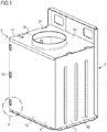
- the FIG. 1 shows a perspective view of a fume hood housing 1.
- the side walls 10, 20 are L-shaped, wherein a side wall 10, a side 3 and the front side 4 and another side wall 20, the second side 5 and the rear wall 6 of the extractor housing 1 form.
- the hollow profile-shaped basic body formed by the side walls 10, 20 is covered by a cover element 30.
- the cover element 30 has an opening for the passage of an exhaust air nozzle of a fan housing (not shown).
- An opening or bore 31 for a connecting and earthing screw or tapping screw for the earth circuit is also provided on the cover element 30.
- FIG. 2 is only an L-shaped side wall 20 and the cover member 30th the extractor housing 1 shown.
- the side wall 20 has flanges 24 at the lateral edge of the leg which forms the side 5 and at the upper edge of this side 5.
- the upper flange 24 is covered in this view by the cover member 30 but in FIG. 1 To recognize in sections.
- three in an imaginary line mutually arranged recesses 21 are provided.
- three latching hooks 22 are also arranged one above the other.
- L-shaped side wall 10 has a similar structure.
- the extension which is provided on the rear wall 6 for fixing the extractor housing 1 to a wall, recessed.
- the front side 4 has the same height as the side 3 with which the L-shaped side wall 10 is formed.
- a flange is provided at the free end of the leg which forms the side 3, in which recesses (not visible) are introduced, and at the free end of the leg which forms the front 4, latching hooks 12 are provided ,
- the latching hooks 12 on the front L-shaped side wall 10 are directed downwards in the illustrated embodiment.
- the latching hooks 22 of the rear L-shaped side wall 20 are directed upward.
- the connection of the two side walls 10 and 20 will be described below essentially with reference to the latching hooks 12 and the recesses 21.
- the further connection between the latching hooks 22 and provided on the side wall 10 recesses is rotated accordingly by 180 °.
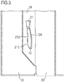
- FIG. 3 shows perspective view of the section A from FIG. 1 at the front lower corner of the extractor housing 1 from the direction of view of the interior of the extractor housing 1.
- the latching hook 12 protruding vertically from the first side wall 10 is inserted through the recess 21 in the front flange 24 of the second side wall 20.
- the recess 21 has a funnel shape in the upper area substantially. This is formed by insertion bevels 211. By this insertion bevels 211, the width of the recess 21 tapers downward. Below the funnel-shaped area, the clamping portion of the recess 21 connects. In this clamping section, three clamping regions 212 are provided in the illustrated embodiment. The clamping regions 212 are formed by projections on the recess 21, which are directed in the direction of the center or longitudinal axis of the recess 21.
- two projections 212 are provided on one recess side, and a projection 212 is provided on the other, that is opposite, recess side.
- the two protrusions 212 on the left-hand recess side are offset from one another to the one protrusion 212 on the opposite recess side, that is, one protrusion 212 lies in the vertical direction between the two other protrusions 212.
- the lower end of the clamping portion of the recess 21, that is, the lower or the funnel-shaped portion facing away from the end 23 of the recess 21 is formed in the illustrated embodiment so that an inserted latching hook 12 due to its weight or the weight of the second side wall 20 or the side wall 10, on which the latching hook 12 is provided, can rest on the underside of the recess 21.
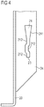
- FIG. 5a shows the in FIG. 3 shown region of the first side wall 10 with the perpendicular protruding from the first side wall 10 latching hooks 12th
- FIG. 5a shows the view from the outside on the area that is in FIG. 3 shown from the inside.
- the latching hook 12 protrudes into the image plane.
- the latching hook 12 is arranged in an opening 13.
- the opening 13 represents the section from which the latching hook 12 has been manufactured or cut out.
- the latching hook 12 has on the underside 121 on the side wall 10 side facing a bevel 122.
- This bevel 122 provides for a Furthermore, a further chamfer 124 is provided on the end face 123 of the latching hook 12, that is to say on the side facing away from the side wall 10, in the recess 21. This bevel 124 also ensures easier insertion of the latching hook 12 into the recess 21.
- a latching gap 126 is formed between the head 125 of the latching hook 12 and the side wall 10. The head 125 of the latching hook 12, on which the chamfers 122, 124 are provided, is thus connected to the side wall 10 via a web, which is also referred to as a latching web 127.
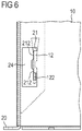
- FIG. 6 is the area A off FIG. 1 shown in front view.
- the flange 24 covers the opening 13 formed in the side wall 10 by the provision of the latching hook 12. Ingress of contaminants into and the escape of noise from the extractor housing 1 can thus be largely prevented despite the simple construction of the side walls 10, 20.
- latching hooks 22 are opposite to the latching hooks 12 of the side wall 10 aligned.
- the latching hooks 22 thus point upwards.
- recesses on a flange (not shown) on the side wall 10, in which the latching hooks 22 are to be introduced rotated by 180 ° to the recesses 21 of the side wall 20th
- the side wall 10 is brought in front of the side wall 20.
- the side walls are positioned so that the latching hooks 12 on the side wall 10 are approximately at the same height with the recesses 21 of the side wall 20.
- the latching hooks 22 of the side wall 20 are brought to about the same height as the recesses on the flange of the side wall 10 ,
- the end faces 123 of the locking hooks 12 are approximately at the height of the funnel-shaped portions of the recesses 21.
- the end faces of the latching hooks 22 of the side wall 20 are approximately at the level of the funnel-shaped portions of the recesses of the side wall 10. At this height, the side wall 10 is moved in the direction of the side wall 20.
- the head 125 of the latching hook 21 is by this movement through the funnel-shaped portion of the recess 21 of the side wall 20 passed.
- the chamfer 124 helps on the front side of the latching hook 12 and ensures a safe insertion of the latching hook 12 in the recess 21 safely. Only when the area surrounding the latching hooks 12 of the corresponding side wall 10 rests against the flange 24 of the respective other side wall 20, the latching gap 126 is aligned with the flange 24. In this position, the side wall 10 is now moved relative to the side wall 20 down.
- the latching gaps 126 of the latching hooks 12 and then the latching web 127 of the latching hooks 12 are brought into contact with the clamping regions 212 of the recesses 21 or guided through them.
- the funnel-shaped region of the recesses 21 in this case ensures that the latching web 127 enters between the clamping regions 212. Due to the weight of the side wall 10, the insertion of the locking webs 127 between the clamping regions 212 of the recesses 21 is facilitated. Once the bottom of the locking webs 127 has reached the bottom 23 of the recesses 21, the side walls 10, 20 are in the mutually locked or interconnected position.
- the cover element 30 can now be placed. If inwardly directed flanges 24 are provided on the sides 3, 5 of the extractor housing 1 at the upper edges, latching hooks (not shown) on the cover element 30 can be brought into engagement therewith.
- the latching hooks are in this case provided on two sides of the cover element 30 and point in the direction of the rear side 6 of the extractor housing 1. This makes it possible to put the cover element 30 from above on the side walls 10, 20 and by moving in the direction of the back 6 of the extractor hood 1 attached to the side walls 10, 20 and the flanges 24.
- the invention is not limited to the illustrated embodiment.
- the catch hooks are all in the same direction, preferably oriented downwards.
- the extractor housing can be made quickly because the individual connections between parts of the extractor housing parallel, that is generated at the same time.
- the invention facilitates the joining of the side walls of the extractor housing by the provided on the recesses Ein Industriesschrägen and provided on the locking hooks bevels.
- the service life of the punching tool necessary for producing the side walls can also be extended with the present invention because of the relatively large gap width of the recesses, which is possible due to the clamping areas provided in the gap. Nevertheless, the present invention enables a reliable attachment of the side walls to each other.
Landscapes
- Engineering & Computer Science (AREA)
- Chemical & Material Sciences (AREA)
- Combustion & Propulsion (AREA)
- Mechanical Engineering (AREA)
- General Engineering & Computer Science (AREA)
- Ventilation (AREA)
Claims (11)
- Parois latérales pour un boîtier de hotte aspirante d'une hotte aspirante, les parois latérales, à l'état assemblé, formant un profilé creux, au moins une paroi latérale (20, 10) présentant au moins un évidement (21) oblong, au moins une deuxième paroi latérale présentant un élément d'encliquetage (12, 22), l'évidement présentant sur sa longueur au moins trois zones de serrage (212) pour la fixation, par adhérence de force, de l'élément d'encliquetage (12, 22) de la deuxième paroi latérale (10, 20) et les zones de serrage étant formées par les surfaces frontales de saillies orientées vers l'axe longitudinal de l'évidement, caractérisées en ce que l'élément d'encliquetage est un crochet d'encliquetage et en ce que les saillies sont décalées les unes par rapport aux autres dans le sens longitudinal de l'évidement.
- Parois latérales d'un boîtier de hotte aspirante selon la revendication 1, caractérisées en ce que l'évidement (21) présente des chanfreins d'insertion (211), notamment des chanfreins d'insertion en forme d'entonnoir.
- Parois latérales d'un boîtier de hotte aspirante selon l'une quelconque des revendications 1 ou 2, caractérisées en ce que l'élément d'encliquetage (12, 22) présente un espace d'encliquetage (126) qui correspond à l'épaisseur de paroi de la paroi latérale (20, 10) dans laquelle l'évidement (21) est placé pour loger l'élément d'encliquetage (12, 22).
- Parois latérales d'un boîtier de hotte aspirante selon l'une quelconque des revendications 1 à 3, caractérisées en ce que l'au moins un élément d'encliquetage (12), notamment le crochet d'encliquetage, est formé dans la matière de la paroi latérale (10) sur laquelle celui-ci fait saillie, et est courbé à partir de la surface de la paroi latérale (20).
- Parois latérales d'un boîtier de hotte aspirante selon l'une quelconque des revendications 1 à 4, caractérisées en ce que l'élément d'encliquetage (12), notamment chaque crochet d'encliquetage, présente au moins un chanfrein (122, 124), le chanfrein (122, 124) étant ménagé sur le côté frontal (123) et/ou sur le côté inférieur (121) de l'élément d'encliquetage (12), notamment du crochet d'encliquetage.
- Parois latérales d'un boîtier de hotte aspirante selon l'une quelconque des revendications 1 à 5, caractérisées en ce que l'au moins un évidement (21) est ménagé sur une bride (24) de l'au moins une paroi latérale (20, 10), la bride (24), inclinée par rapport à l'au moins une paroi latérale (20, 10), étant disposée sur celle-ci, notamment sur un bord de la paroi latérale (20, 10).
- Parois latérales d'un boîtier de hotte aspirante selon l'une quelconque des revendications 1 à 6, caractérisées en ce que l'au moins une deuxième paroi latérale (10, 20) et/ou toutes les parois latérales (10, 20) présente/présentent perpendiculairement à la paroi latérale (10, 20) resp. aux parois latérales (10, 20) des éléments d'encliquetage (12, 22) rigides en saillie, notamment des crochets d'encliquetage.
- Parois latérales d'un boîtier de hotte aspirante selon l'une quelconque des revendications 1 à 7, caractérisées en ce qu'au moins une paroi latérale (10, 20) présente au moins une ouverture de logement pour loger un élément d'encliquetage d'un élément de recouvrement destiné à fixer l'élément de recouvrement (30) sur l'au moins une paroi latérale.
- Parois latérales d'un boîtier de hotte aspirante selon l'une quelconque des revendications 1 à 8, caractérisées en ce que les parois latérales (10, 20) présentent un profil en forme de L.
- Boîtier de hotte aspirante comprenant des parois latérales qui forment un profilé creux à l'état assemblé, et comprenant un élément de recouvrement, lequel recouvre le profilé creux sur un côté, caractérisé en ce que les parois latérales (10, 20) sont réalisées selon l'une quelconque des revendications 1 à 9.
- Hotte aspirante comprenant un boîtier de hotte aspirante, caractérisée en ce que le boîtier de hotte aspirante (1) présente des parois latérales (10, 20) selon l'une quelconque des revendications 1 à 9.
Applications Claiming Priority (2)
| Application Number | Priority Date | Filing Date | Title |
|---|---|---|---|
| DE102007021319A DE102007021319A1 (de) | 2007-05-07 | 2007-05-07 | Seitenwände eines Dunstabzugsgehäuses, Dunstabzugsgehäuse und Dunstabzugshaube |
| PCT/EP2008/054806 WO2008135374A1 (fr) | 2007-05-07 | 2008-04-21 | Parois latérales d'un logement pour hotte aspirante, logement pour hotte aspirante et hotte aspirante correspondante |
Publications (2)
| Publication Number | Publication Date |
|---|---|
| EP2145135A1 EP2145135A1 (fr) | 2010-01-20 |
| EP2145135B1 true EP2145135B1 (fr) | 2018-06-13 |
Family
ID=39650640
Family Applications (1)
| Application Number | Title | Priority Date | Filing Date |
|---|---|---|---|
| EP08736422.0A Active EP2145135B1 (fr) | 2007-05-07 | 2008-04-21 | Parois latérales d'un logement pour hotte aspirante, logement pour hotte aspirante et hotte aspirante correspondante |
Country Status (3)
| Country | Link |
|---|---|
| EP (1) | EP2145135B1 (fr) |
| DE (1) | DE102007021319A1 (fr) |
| WO (1) | WO2008135374A1 (fr) |
Families Citing this family (2)
| Publication number | Priority date | Publication date | Assignee | Title |
|---|---|---|---|---|
| DE102009055077A1 (de) * | 2009-12-21 | 2011-06-22 | BSH Bosch und Siemens Hausgeräte GmbH, 81739 | Lüfterkasten für Dunstabzugshaube |
| DE102015212283B4 (de) * | 2015-07-01 | 2021-02-18 | BSH Hausgeräte GmbH | Lüftergehäuse für eine Dunstabzugshaube |
Family Cites Families (4)
| Publication number | Priority date | Publication date | Assignee | Title |
|---|---|---|---|---|
| DE10360897A1 (de) * | 2003-12-23 | 2005-07-21 | BSH Bosch und Siemens Hausgeräte GmbH | Verbindungseinrichtung für eine Dunstabzugsvorrichtung |
| NL1025719C2 (nl) * | 2004-03-13 | 2005-09-14 | Vika Metaal B V | Samenstel van mechanisch koppelbare plaatdelen. |
| DE102004042570A1 (de) * | 2004-09-02 | 2006-03-09 | BSH Bosch und Siemens Hausgeräte GmbH | Kamin für Dunstabzugshaube |
| NL1028875C1 (nl) * | 2004-09-10 | 2006-03-13 | Gijsbert Michiel Zijlstra | Verbinding van twee platen. |
-
2007
- 2007-05-07 DE DE102007021319A patent/DE102007021319A1/de not_active Withdrawn
-
2008
- 2008-04-21 EP EP08736422.0A patent/EP2145135B1/fr active Active
- 2008-04-21 WO PCT/EP2008/054806 patent/WO2008135374A1/fr active Application Filing
Non-Patent Citations (1)
| Title |
|---|
| None * |
Also Published As
| Publication number | Publication date |
|---|---|
| WO2008135374A1 (fr) | 2008-11-13 |
| EP2145135A1 (fr) | 2010-01-20 |
| DE102007021319A1 (de) | 2008-11-13 |
Similar Documents
| Publication | Publication Date | Title |
|---|---|---|
| EP3384567B1 (fr) | Châssis pour armoire électrique | |
| EP1956942B1 (fr) | Systeme de liaison permettant de relier un appareil a encastrer a un meuble et dispositif de meuble | |
| EP0939984B1 (fr) | Armoire de distribution | |
| EP3217099B1 (fr) | Hotte aspirante | |
| EP2570733A1 (fr) | Agencement destiné à la fixation d'un dispositif de hotte aspirante | |
| EP2559120B1 (fr) | Partie boîtier pour une armoire de commande | |
| EP2145135B1 (fr) | Parois latérales d'un logement pour hotte aspirante, logement pour hotte aspirante et hotte aspirante correspondante | |
| EP2123980A2 (fr) | Dispositif d'aspiration de vapeur et procédé de montage d'un dispositif de cheminée de ventilation | |
| EP2469189A2 (fr) | Hotte aspirante équipée d'un dispositif de fixation d'un écran à vapeur et procédé de fixation | |
| EP3026350B1 (fr) | Hotte aspirante dotée d'un composant | |
| EP2378209A2 (fr) | Hotte aspirante | |
| EP3608588B1 (fr) | Ressort de maintien pour luminaire | |
| DE102008013004B4 (de) | Anordnung mit einem Kochfeld und einer Arbeitsplatte | |
| DE102015212283B4 (de) | Lüftergehäuse für eine Dunstabzugshaube | |
| DE102004051928B4 (de) | Befestigungselement für ein Gehäuse und Befestigungssystem bestehend aus einem Gehäuse, einer Montageplatte und einem Befestigungselement | |
| EP3071896B1 (fr) | Support de montage pour une enceinte et méthode de monter une enceinte utilisant ledit support | |
| DE102017114389B4 (de) | Anordnung aus einem Schaltschranksockel und einem darauf montierten Schaltschrankrahmengestell sowie eine entsprechende Schaltschrankreihe | |
| DE102013103594B4 (de) | Halteteil für eine Montageplatte, Türbetätiger-Anordnung und Verfahren zum Montieren einer Türbetätiger-Anordnung | |
| EP2354697A2 (fr) | Cadre de fixation pour une grille d'aération | |
| DE102004042230A1 (de) | Montagesystem für eine an einer Wand befestigbare Dunstabzugshaube | |
| DE102005049801A1 (de) | Bauteil mit einem Grundkörper und mit wenigstens einem Rastverbindungselement | |
| DE102015010031B4 (de) | Rahmen für eine Leuchte | |
| EP1528648B1 (fr) | Dispositif pour fixer un appareil de refroidissement sur une armoire électrique | |
| DE102014216554A1 (de) | Tür für ein Haushaltsgerät mit einem ein Zentrierelement umfassendes Verbindungselement, Haushaltsgerät mit einer derartigen Tür sowie Verfahren zur Montage einer Tür | |
| DE102013113201A1 (de) | Rahmenprofil für ein Rahmengestell eines Schrankes, insbesondere eines Schaltschrankes |
Legal Events
| Date | Code | Title | Description |
|---|---|---|---|
| PUAI | Public reference made under article 153(3) epc to a published international application that has entered the european phase |
Free format text: ORIGINAL CODE: 0009012 |
|
| 17P | Request for examination filed |
Effective date: 20091207 |
|
| AK | Designated contracting states |
Kind code of ref document: A1 Designated state(s): AT BE BG CH CY CZ DE DK EE ES FI FR GB GR HR HU IE IS IT LI LT LU LV MC MT NL NO PL PT RO SE SI SK TR |
|
| AX | Request for extension of the european patent |
Extension state: AL BA MK RS |
|
| DAX | Request for extension of the european patent (deleted) | ||
| RAP1 | Party data changed (applicant data changed or rights of an application transferred) |
Owner name: BSH HAUSGERAETE GMBH |
|
| 17Q | First examination report despatched |
Effective date: 20160429 |
|
| GRAP | Despatch of communication of intention to grant a patent |
Free format text: ORIGINAL CODE: EPIDOSNIGR1 |
|
| STAA | Information on the status of an ep patent application or granted ep patent |
Free format text: STATUS: GRANT OF PATENT IS INTENDED |
|
| INTG | Intention to grant announced |
Effective date: 20171130 |
|
| GRAS | Grant fee paid |
Free format text: ORIGINAL CODE: EPIDOSNIGR3 |
|
| GRAA | (expected) grant |
Free format text: ORIGINAL CODE: 0009210 |
|
| STAA | Information on the status of an ep patent application or granted ep patent |
Free format text: STATUS: THE PATENT HAS BEEN GRANTED |
|
| AK | Designated contracting states |
Kind code of ref document: B1 Designated state(s): AT BE BG CH CY CZ DE DK EE ES FI FR GB GR HR HU IE IS IT LI LT LU LV MC MT NL NO PL PT RO SE SI SK TR |
|
| REG | Reference to a national code |
Ref country code: GB Ref legal event code: FG4D Free format text: NOT ENGLISH |
|
| REG | Reference to a national code |
Ref country code: CH Ref legal event code: EP Ref country code: AT Ref legal event code: REF Ref document number: 1008891 Country of ref document: AT Kind code of ref document: T Effective date: 20180615 |
|
| REG | Reference to a national code |
Ref country code: IE Ref legal event code: FG4D Free format text: LANGUAGE OF EP DOCUMENT: GERMAN |
|
| REG | Reference to a national code |
Ref country code: DE Ref legal event code: R096 Ref document number: 502008016132 Country of ref document: DE |
|
| REG | Reference to a national code |
Ref country code: NL Ref legal event code: MP Effective date: 20180613 |
|
| REG | Reference to a national code |
Ref country code: LT Ref legal event code: MG4D |
|
| PG25 | Lapsed in a contracting state [announced via postgrant information from national office to epo] |
Ref country code: BG Free format text: LAPSE BECAUSE OF FAILURE TO SUBMIT A TRANSLATION OF THE DESCRIPTION OR TO PAY THE FEE WITHIN THE PRESCRIBED TIME-LIMIT Effective date: 20180913 Ref country code: FI Free format text: LAPSE BECAUSE OF FAILURE TO SUBMIT A TRANSLATION OF THE DESCRIPTION OR TO PAY THE FEE WITHIN THE PRESCRIBED TIME-LIMIT Effective date: 20180613 Ref country code: NO Free format text: LAPSE BECAUSE OF FAILURE TO SUBMIT A TRANSLATION OF THE DESCRIPTION OR TO PAY THE FEE WITHIN THE PRESCRIBED TIME-LIMIT Effective date: 20180913 Ref country code: CY Free format text: LAPSE BECAUSE OF FAILURE TO SUBMIT A TRANSLATION OF THE DESCRIPTION OR TO PAY THE FEE WITHIN THE PRESCRIBED TIME-LIMIT Effective date: 20180613 Ref country code: SE Free format text: LAPSE BECAUSE OF FAILURE TO SUBMIT A TRANSLATION OF THE DESCRIPTION OR TO PAY THE FEE WITHIN THE PRESCRIBED TIME-LIMIT Effective date: 20180613 Ref country code: LT Free format text: LAPSE BECAUSE OF FAILURE TO SUBMIT A TRANSLATION OF THE DESCRIPTION OR TO PAY THE FEE WITHIN THE PRESCRIBED TIME-LIMIT Effective date: 20180613 Ref country code: ES Free format text: LAPSE BECAUSE OF FAILURE TO SUBMIT A TRANSLATION OF THE DESCRIPTION OR TO PAY THE FEE WITHIN THE PRESCRIBED TIME-LIMIT Effective date: 20180613 |
|
| PG25 | Lapsed in a contracting state [announced via postgrant information from national office to epo] |
Ref country code: LV Free format text: LAPSE BECAUSE OF FAILURE TO SUBMIT A TRANSLATION OF THE DESCRIPTION OR TO PAY THE FEE WITHIN THE PRESCRIBED TIME-LIMIT Effective date: 20180613 Ref country code: HR Free format text: LAPSE BECAUSE OF FAILURE TO SUBMIT A TRANSLATION OF THE DESCRIPTION OR TO PAY THE FEE WITHIN THE PRESCRIBED TIME-LIMIT Effective date: 20180613 Ref country code: GR Free format text: LAPSE BECAUSE OF FAILURE TO SUBMIT A TRANSLATION OF THE DESCRIPTION OR TO PAY THE FEE WITHIN THE PRESCRIBED TIME-LIMIT Effective date: 20180914 |
|
| PG25 | Lapsed in a contracting state [announced via postgrant information from national office to epo] |
Ref country code: NL Free format text: LAPSE BECAUSE OF FAILURE TO SUBMIT A TRANSLATION OF THE DESCRIPTION OR TO PAY THE FEE WITHIN THE PRESCRIBED TIME-LIMIT Effective date: 20180613 |
|
| PG25 | Lapsed in a contracting state [announced via postgrant information from national office to epo] |
Ref country code: EE Free format text: LAPSE BECAUSE OF FAILURE TO SUBMIT A TRANSLATION OF THE DESCRIPTION OR TO PAY THE FEE WITHIN THE PRESCRIBED TIME-LIMIT Effective date: 20180613 Ref country code: PL Free format text: LAPSE BECAUSE OF FAILURE TO SUBMIT A TRANSLATION OF THE DESCRIPTION OR TO PAY THE FEE WITHIN THE PRESCRIBED TIME-LIMIT Effective date: 20180613 Ref country code: IS Free format text: LAPSE BECAUSE OF FAILURE TO SUBMIT A TRANSLATION OF THE DESCRIPTION OR TO PAY THE FEE WITHIN THE PRESCRIBED TIME-LIMIT Effective date: 20181013 Ref country code: CZ Free format text: LAPSE BECAUSE OF FAILURE TO SUBMIT A TRANSLATION OF THE DESCRIPTION OR TO PAY THE FEE WITHIN THE PRESCRIBED TIME-LIMIT Effective date: 20180613 Ref country code: RO Free format text: LAPSE BECAUSE OF FAILURE TO SUBMIT A TRANSLATION OF THE DESCRIPTION OR TO PAY THE FEE WITHIN THE PRESCRIBED TIME-LIMIT Effective date: 20180613 Ref country code: SK Free format text: LAPSE BECAUSE OF FAILURE TO SUBMIT A TRANSLATION OF THE DESCRIPTION OR TO PAY THE FEE WITHIN THE PRESCRIBED TIME-LIMIT Effective date: 20180613 |
|
| PG25 | Lapsed in a contracting state [announced via postgrant information from national office to epo] |
Ref country code: IT Free format text: LAPSE BECAUSE OF FAILURE TO SUBMIT A TRANSLATION OF THE DESCRIPTION OR TO PAY THE FEE WITHIN THE PRESCRIBED TIME-LIMIT Effective date: 20180613 |
|
| REG | Reference to a national code |
Ref country code: DE Ref legal event code: R097 Ref document number: 502008016132 Country of ref document: DE |
|
| PLBE | No opposition filed within time limit |
Free format text: ORIGINAL CODE: 0009261 |
|
| STAA | Information on the status of an ep patent application or granted ep patent |
Free format text: STATUS: NO OPPOSITION FILED WITHIN TIME LIMIT |
|
| 26N | No opposition filed |
Effective date: 20190314 |
|
| PG25 | Lapsed in a contracting state [announced via postgrant information from national office to epo] |
Ref country code: SI Free format text: LAPSE BECAUSE OF FAILURE TO SUBMIT A TRANSLATION OF THE DESCRIPTION OR TO PAY THE FEE WITHIN THE PRESCRIBED TIME-LIMIT Effective date: 20180613 Ref country code: DK Free format text: LAPSE BECAUSE OF FAILURE TO SUBMIT A TRANSLATION OF THE DESCRIPTION OR TO PAY THE FEE WITHIN THE PRESCRIBED TIME-LIMIT Effective date: 20180613 |
|
| REG | Reference to a national code |
Ref country code: CH Ref legal event code: PL |
|
| REG | Reference to a national code |
Ref country code: BE Ref legal event code: MM Effective date: 20190430 |
|
| GBPC | Gb: european patent ceased through non-payment of renewal fee |
Effective date: 20190421 |
|
| PG25 | Lapsed in a contracting state [announced via postgrant information from national office to epo] |
Ref country code: MC Free format text: LAPSE BECAUSE OF FAILURE TO SUBMIT A TRANSLATION OF THE DESCRIPTION OR TO PAY THE FEE WITHIN THE PRESCRIBED TIME-LIMIT Effective date: 20180613 Ref country code: LU Free format text: LAPSE BECAUSE OF NON-PAYMENT OF DUE FEES Effective date: 20190421 |
|
| PG25 | Lapsed in a contracting state [announced via postgrant information from national office to epo] |
Ref country code: LI Free format text: LAPSE BECAUSE OF NON-PAYMENT OF DUE FEES Effective date: 20190430 Ref country code: CH Free format text: LAPSE BECAUSE OF NON-PAYMENT OF DUE FEES Effective date: 20190430 Ref country code: GB Free format text: LAPSE BECAUSE OF NON-PAYMENT OF DUE FEES Effective date: 20190421 |
|
| PG25 | Lapsed in a contracting state [announced via postgrant information from national office to epo] |
Ref country code: BE Free format text: LAPSE BECAUSE OF NON-PAYMENT OF DUE FEES Effective date: 20190430 Ref country code: FR Free format text: LAPSE BECAUSE OF NON-PAYMENT OF DUE FEES Effective date: 20190430 |
|
| PG25 | Lapsed in a contracting state [announced via postgrant information from national office to epo] |
Ref country code: TR Free format text: LAPSE BECAUSE OF FAILURE TO SUBMIT A TRANSLATION OF THE DESCRIPTION OR TO PAY THE FEE WITHIN THE PRESCRIBED TIME-LIMIT Effective date: 20180613 |
|
| PG25 | Lapsed in a contracting state [announced via postgrant information from national office to epo] |
Ref country code: IE Free format text: LAPSE BECAUSE OF NON-PAYMENT OF DUE FEES Effective date: 20190421 |
|
| PG25 | Lapsed in a contracting state [announced via postgrant information from national office to epo] |
Ref country code: PT Free format text: LAPSE BECAUSE OF FAILURE TO SUBMIT A TRANSLATION OF THE DESCRIPTION OR TO PAY THE FEE WITHIN THE PRESCRIBED TIME-LIMIT Effective date: 20181015 |
|
| REG | Reference to a national code |
Ref country code: AT Ref legal event code: MM01 Ref document number: 1008891 Country of ref document: AT Kind code of ref document: T Effective date: 20190421 |
|
| PG25 | Lapsed in a contracting state [announced via postgrant information from national office to epo] |
Ref country code: AT Free format text: LAPSE BECAUSE OF NON-PAYMENT OF DUE FEES Effective date: 20190421 |
|
| PG25 | Lapsed in a contracting state [announced via postgrant information from national office to epo] |
Ref country code: MT Free format text: LAPSE BECAUSE OF FAILURE TO SUBMIT A TRANSLATION OF THE DESCRIPTION OR TO PAY THE FEE WITHIN THE PRESCRIBED TIME-LIMIT Effective date: 20180613 Ref country code: HU Free format text: LAPSE BECAUSE OF FAILURE TO SUBMIT A TRANSLATION OF THE DESCRIPTION OR TO PAY THE FEE WITHIN THE PRESCRIBED TIME-LIMIT; INVALID AB INITIO Effective date: 20080421 |
|
| REG | Reference to a national code |
Ref country code: DE Ref legal event code: R084 Ref document number: 502008016132 Country of ref document: DE |
|
| PGFP | Annual fee paid to national office [announced via postgrant information from national office to epo] |
Ref country code: DE Payment date: 20230430 Year of fee payment: 16 |