EP2827002A2 - Verfahren zur Herstellung einer Rotorbaugruppe - Google Patents
Verfahren zur Herstellung einer Rotorbaugruppe Download PDFInfo
- Publication number
- EP2827002A2 EP2827002A2 EP14177341.6A EP14177341A EP2827002A2 EP 2827002 A2 EP2827002 A2 EP 2827002A2 EP 14177341 A EP14177341 A EP 14177341A EP 2827002 A2 EP2827002 A2 EP 2827002A2
- Authority
- EP
- European Patent Office
- Prior art keywords
- shaft
- bore
- impeller
- rotor core
- adhesive
- Prior art date
- Legal status (The legal status is an assumption and is not a legal conclusion. Google has not performed a legal analysis and makes no representation as to the accuracy of the status listed.)
- Withdrawn
Links
- 238000004519 manufacturing process Methods 0.000 title claims abstract description 15
- 239000000853 adhesive Substances 0.000 claims abstract description 43
- 230000001070 adhesive effect Effects 0.000 claims abstract description 43
- 238000000034 method Methods 0.000 claims description 16
- 229910052761 rare earth metal Inorganic materials 0.000 description 6
- 150000002910 rare earth metals Chemical class 0.000 description 6
- 238000003780 insertion Methods 0.000 description 5
- 230000037431 insertion Effects 0.000 description 5
- 239000000696 magnetic material Substances 0.000 description 5
- 239000000463 material Substances 0.000 description 5
- 230000002411 adverse Effects 0.000 description 1
- 230000000712 assembly Effects 0.000 description 1
- 238000000429 assembly Methods 0.000 description 1
- 230000003247 decreasing effect Effects 0.000 description 1
- 229910052751 metal Inorganic materials 0.000 description 1
- 239000002184 metal Substances 0.000 description 1
- 230000036316 preload Effects 0.000 description 1
Images


Classifications
-
- F—MECHANICAL ENGINEERING; LIGHTING; HEATING; WEAPONS; BLASTING
- F04—POSITIVE - DISPLACEMENT MACHINES FOR LIQUIDS; PUMPS FOR LIQUIDS OR ELASTIC FLUIDS
- F04D—NON-POSITIVE-DISPLACEMENT PUMPS
- F04D29/00—Details, component parts, or accessories
- F04D29/26—Rotors specially for elastic fluids
- F04D29/263—Rotors specially for elastic fluids mounting fan or blower rotors on shafts
-
- F—MECHANICAL ENGINEERING; LIGHTING; HEATING; WEAPONS; BLASTING
- F16—ENGINEERING ELEMENTS AND UNITS; GENERAL MEASURES FOR PRODUCING AND MAINTAINING EFFECTIVE FUNCTIONING OF MACHINES OR INSTALLATIONS; THERMAL INSULATION IN GENERAL
- F16D—COUPLINGS FOR TRANSMITTING ROTATION; CLUTCHES; BRAKES
- F16D1/00—Couplings for rigidly connecting two coaxial shafts or other movable machine elements
- F16D1/06—Couplings for rigidly connecting two coaxial shafts or other movable machine elements for attachment of a member on a shaft or on a shaft-end
- F16D1/064—Couplings for rigidly connecting two coaxial shafts or other movable machine elements for attachment of a member on a shaft or on a shaft-end non-disconnectable
- F16D1/068—Couplings for rigidly connecting two coaxial shafts or other movable machine elements for attachment of a member on a shaft or on a shaft-end non-disconnectable involving gluing, welding or the like
-
- F—MECHANICAL ENGINEERING; LIGHTING; HEATING; WEAPONS; BLASTING
- F04—POSITIVE - DISPLACEMENT MACHINES FOR LIQUIDS; PUMPS FOR LIQUIDS OR ELASTIC FLUIDS
- F04D—NON-POSITIVE-DISPLACEMENT PUMPS
- F04D29/00—Details, component parts, or accessories
- F04D29/02—Selection of particular materials
- F04D29/023—Selection of particular materials especially adapted for elastic fluid pumps
-
- F—MECHANICAL ENGINEERING; LIGHTING; HEATING; WEAPONS; BLASTING
- F04—POSITIVE - DISPLACEMENT MACHINES FOR LIQUIDS; PUMPS FOR LIQUIDS OR ELASTIC FLUIDS
- F04D—NON-POSITIVE-DISPLACEMENT PUMPS
- F04D29/00—Details, component parts, or accessories
- F04D29/26—Rotors specially for elastic fluids
- F04D29/266—Rotors specially for elastic fluids mounting compressor rotors on shafts
-
- F—MECHANICAL ENGINEERING; LIGHTING; HEATING; WEAPONS; BLASTING
- F04—POSITIVE - DISPLACEMENT MACHINES FOR LIQUIDS; PUMPS FOR LIQUIDS OR ELASTIC FLUIDS
- F04D—NON-POSITIVE-DISPLACEMENT PUMPS
- F04D29/00—Details, component parts, or accessories
- F04D29/60—Mounting; Assembling; Disassembling
- F04D29/62—Mounting; Assembling; Disassembling of radial or helico-centrifugal pumps
- F04D29/622—Adjusting the clearances between rotary and stationary parts
-
- F—MECHANICAL ENGINEERING; LIGHTING; HEATING; WEAPONS; BLASTING
- F04—POSITIVE - DISPLACEMENT MACHINES FOR LIQUIDS; PUMPS FOR LIQUIDS OR ELASTIC FLUIDS
- F04D—NON-POSITIVE-DISPLACEMENT PUMPS
- F04D29/00—Details, component parts, or accessories
- F04D29/60—Mounting; Assembling; Disassembling
- F04D29/62—Mounting; Assembling; Disassembling of radial or helico-centrifugal pumps
- F04D29/624—Mounting; Assembling; Disassembling of radial or helico-centrifugal pumps especially adapted for elastic fluid pumps
- F04D29/626—Mounting or removal of fans
Definitions
- the present invention relates to a method of manufacturing a rotor assembly for a compressor.
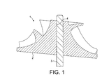
- Figure 1 illustrates an example of a rotor assembly 1 in which an impeller 2 has been press fit onto a shaft 3.
- the bore 4 into which the shaft 3 has been press fit is misaligned.
- the impeller 2 and shaft 3 are typically manufactured using high-precision processes that achieve tight tolerances.
- high-precision manufacturing is expensive and precludes the use of certain materials and processes that are otherwise not capable of achieving the necessary tolerances.
- JP2008-160959 describes a method of assembling a rotor comprising a shaft and a magnet. Adhesive is applied to the outer surface of the shaft and the inner surface of the magnet. The magnet is then mounted to the shaft and aligned using a positioning jig. The magnet and shaft are then removed from the jig and placed into a thermostatic tank in order to cure the adhesive.
- the present invention provides a method of manufacturing a rotor assembly comprising: providing a shaft; providing an impeller; and adhering the shaft within a bore in the impeller, characterised in that the tolerance in the concentricity of the shaft relative to the impeller is smaller than that of the bore, and adhering the shaft within the bore comprises applying an adhesive to the shaft and inserting the shaft into the bore.
- the method has the advantage of providing good adhesive coverage between the shaft and the impeller, thereby ensuring a good join.
- the method may comprise mounting each of the shaft and the impeller in one half of a jig, the two halves of the jig being aligned. The method would then further comprise bringing the two halves of the jig together. One half of the jig may be rotated relative to the other half of the jig. By rotating one half of the jig relative to the other half, as the two halves are brought together, good adhesive coverage between the shaft and impeller is provided.
- the radius of the shaft may have a first tolerance
- the radius of the bore may have a second tolerance
- the concentricity of the bore may have a third tolerance.
- the step of providing the impeller would then preferably comprise providing the impeller with a bore of nominal radius greater than the nominal radius of the shaft by at least the sum of the first, second and third tolerances.
- a bore is then provided of sufficient radius that the shaft may be secured within the bore such that it has a tighter concentric tolerance than that of the bore.
- the method includes providing the impeller with a bore of nominal radius that is greater than the nominal radius of the shaft by at least the sum of the first, second and third tolerances and a nominal radial gap. Accordingly, at the worst tolerance condition, a radial gap exists between the shaft and the bore that encourages wicking of the adhesive.
- a rotor assembly comprising a shaft and an impeller, the shaft being secured within a bore of the impeller by adhesive, wherein the bore and the shaft each have a tolerance in concentricity relative to the impeller, and the tolerance in the concentricity of the shaft is smaller than that of the bore.
- a rotor assembly having tighter tolerances in concentricity may be achieved without the need for high-precision manufacturing.
- the rotor assembly may therefore be manufactured more cheaply.
- the components of the rotor assembly may be manufactured using materials and processes that would otherwise be precluded form use owing to their associated tolerances.
- the ratio of the tolerance in the concentricity of the shaft and the bore is no greater than 0.9. This then corresponds to an improvement in concentricity of 10%.
- the tolerance in the concentricity of the shaft is no greater than 0.07 mm.
- the rotor assembly comprises an impeller and a rotor core, and the shaft is secured within a bore in each of the impeller and the rotor core by adhesive.
- the tolerances in the concentricity of the shaft relative to the impeller and the rotor core are then smaller than the tolerances in the concentricity of the bores in the impeller and rotor core respectively. This then has the advantage that balancing of the rotor assembly is made easier since the impeller and rotor core, which each provide a significant moment of inertia, have tighter concentricities with the shaft and with each other.
- the rotor assembly comprises a bearing cartridge located between the impeller and the rotor core.
- the bearing cartridge which ideally comprises a pair of spaced bearings surrounded by a sleeve, provides a single fastening of relatively large surface area over which the rotor assembly may be secured to a frame, housing or the like.
- radial loading of each of the bearings may be more evenly balanced, thereby prolonging the life of the bearing cartridge.
- the impeller may be formed of plastic, thereby providing a cheap, lightweight impeller for which a relatively tight concentricity may nevertheless be achieved.
- the rotor core may be formed of a rare-earth magnetic material. This then has the advantage of providing excellent magnetic properties. Since the concentricity of the shaft relative to the rotor core is improved, balancing of the rotor assembly is made easier. This is particularly useful when the rotor core is formed of a rare-earth magnetic material, since mass cannot easily be removed from the rotor core owing to the brittle nature of the material.
- the rotor assembly 10 of Figure 2 comprises a shaft 11, an impeller 12, a rotor core 13 and a bearing cartridge 14.
- the impeller 12 and rotor core 13 are secured to the shaft 11 at opposite ends of the shaft 11.
- the bearing cartridge 14 is secured to the shaft 11 between the impeller 12 and the rotor core 13.
- the impeller 12 includes a bore 15 into which the shaft 11 is secured by means of an adhesive 17. Owing to tolerances in the manufacture of the impeller 12, the bore 15 has a tolerance in concentricity relative to a centreline of the impeller 12. The shaft 11 similarly has a tolerance in concentricity relative to a centreline of the impeller 12. However, the shaft 11 is secured within the bore 15 such that the tolerance in the concentricity of the shaft 11 is smaller than that of the bore 15.
- the impeller 12 illustrated in Figure 2 is a centrifugal impeller. However, other types of impeller might equally be employed according to the intended application of the rotor assembly 10.
- the rotor core 13 comprises a cylindrical body formed of a hard or soft magnetic material.
- the rotor core 13 includes a bore 16 into which the shaft 11 is secured by means of an adhesive 17.
- the bore 16 has a tolerance in concentricity relative to a centreline of the rotor core 13.
- the shaft 11 similarly has a tolerance in concentricity relative to a centreline of the rotor core 13.
- the shaft 11 is secured within the bore 16 such that the tolerance in the concentricity of the shaft 11 is smaller than that of the bore 16.
- the rotor core 13 illustrated in Figure 2 comprises a single cylindrical body
- the rotor core 13 might equally be formed of a plurality of stacked rings, each ring comprising a bore into which the shaft 11 is secured by an adhesive 17.
- the bearing cartridge 14 comprises a pair of spaced bearings 18,19, a spring 20, and a sleeve 21.
- the spring 20 surrounds the shaft 11 and applies a preload to each of the bearings 18,19.
- the sleeve 21 surrounds the bearings 18,19 and the spring 20, and provides a surface over which the rotor assembly 10 may be secured to a frame, housing or the like of a compressor.
- the bearing cartridge 14 provides effective support for the rotor assembly 10. By locating the impeller 12 and rotor core 13 on opposite sides of the bearing cartridge 14, radial loading of each of the bearings 18,19 is more evenly balanced, thereby prolonging the life of the bearings 18,19.
- the bearing cartridge 14 is first secured to the shaft 11.
- the manner in which the bearing cartridge 14 is secured to the shaft 11 is not pertinent to the present invention.
- the bearings 18,19 may be press fit onto the shaft 2 and the sleeve 22 may then be press fit or adhered over the bearings 18,19.
- the bearing cartridge 14 is manufactured to tight tolerances. Consequently, when secured to the shaft 11, the tolerance in the concentricity of the shaft 11 relative to the bearing cartridge 14 is relatively small.
- the rotor core 13 is then secured to one end of the shaft 11. This is achieved by mounting the shaft 11 in one half of a jig, and mounting the rotor core 13 in the other half of the jig. The two halves of the jig are aligned such that the shaft 11 and rotor core 13 are concentric. Referring now to Figure 3 , a spot of adhesive 17 is applied to the shaft 11 at a short distance from the free end of the shaft 11, Figure 3(a) . The two halves of the jig are brought together such that the shaft 11 is inserted into the bore 16 of the rotor core 13. The shaft 11 is inserted up to a point at which the rotor core 13 contacts the spot of adhesive 17.
- the adhesive 17 may begin to cure, which in turn increases the viscosity and reduces the wicking of the adhesive 17. Since insufficient coverage may result in subsequent failure of the adhesive 17, the speed of insertion of the shaft 11 is ideally controlled so as to achieve good adhesive coverage.
- the impeller 12 is then secured to the free end of the shaft 11.
- the manner in which the impeller 12 is secured to the shaft 11 is almost identical to that of the rotor core 13.
- the bearing cartridge 14, rather than the shaft 11 is directly held by the jig.
- the impeller 12 is otherwise secured to the shaft 11 in the same manner as that described above for the rotor core 13.
- a spot of adhesive 17 is applied to the shaft 11, one half of the jig is rotated relative to the other half, and the two halves of the jig are brought together such that the shaft 11 is inserted into the bore 15 of the impeller 12.
- the speed of translation and rotation of one half of the jig relative to the other half is controlled so as to achieve good coverage of adhesive 17 between the shaft 11 and the impeller 12.
- the bearing cartridge 14 When securing the impeller 12 to the shaft 11, the bearing cartridge 14 is directly held by the jig. Alternatively, the rotor core 13 might be directly held by the jig. However, the outer diameter of the bearing cartridge 14 typically has a tighter tolerance than that of the rotor core 13; this is particularly true when the rotor core 13 is formed of a sintered or bonded magnetic material for which relatively tight tolerances are difficult to achieve. It is for this reason that the bearing cartridge 14, rather than the rotor core 13, is ideally held when securing the impeller 12 to the shaft 11. Nevertheless, when holding the bearing cartridge 14, the jig also holds or otherwise applies a frictional force to the rotor core 13. This then ensures that the shaft 11 rotates relative to the impeller 11, rather than the bearing cartridge 14, as the two halves of the jig are brought together.
- rotor assembly 10 For the particular design of rotor assembly 10 illustrated in Figure 2 , it is not possible to hold the shaft 11 directly in the jig when securing the impeller 12. Nevertheless, for alternative designs of rotor assembly, it may be possible to hold the shaft 11 directly.
- the shaft 11 of the rotor assembly 10 of Figure 2 might be lengthened so as to protrude beyond the end of the rotor core 13.
- the bearing cartridge 14 may be spaced from the rotor core 13 so as to expose a portion of the shaft 11 that can then be held by the jig.
- the rotor core 13 is initially secured to the shaft 11, subsequently followed by the impeller 12, the order by which the impeller 12 and rotor core 13 are secured to the shaft 11 is not essential.
- the impeller 12 might equally be secured to the shaft 11 before the rotor core 13.
- assembly is typically easier if the smaller item is secured first to the shaft 11.
- the radial gap between the shaft 11 and bore 15,16 increases, the volume of air needed to be driven out by the adhesive 17 increases. Consequently, the speed at which the shaft 11 is inserted into the bore 15,16 is ideally decreased so as to reduce the likelihood of air entrapment. In addition to a slower shaft insertion speed, a larger gap naturally requires more adhesive 17. Not only does this increase cost but it also increases the length of time necessary to cure the adhesive 17 and potentially leads to a weaker joint. Accordingly, the gap between the shaft 11 and the bore 15,16 is ideally no bigger than that necessary to achieve good wicking and thus good adhesive coverage. As is explained below, the bores 15,16 of the impeller 12 and rotor core 13 are sized so to permit concentric insertion of the shaft 11 into the bores 15,16. Accordingly, the radius of each bore 15,16 is greater than that of the shaft 11 by an amount that accounts for the tolerance stack. The size of the radial gap between the shaft 11 and each bore 15,16 will therefore be influenced by the size of the tolerance stack.
- each of the shaft 2 and the bores 15,16 has a tolerance. Additionally, there is a tolerance associated with the concentricity of each bore 15,16. In order that the shaft 11 can be inserted into each bore 15,8 such that the shaft 11 is concentric with the impeller 12 and the rotor core 13, the nominal radius of each bore 15,16 is greater than the nominal radius of the shaft 11 by at least an amount that accounts for the radial and concentric tolerances.
- the nominal radius of the bore, r may be represented as: r ⁇ s + ⁇ s + ⁇ b + ⁇ c .
- the impeller 12 and rotor core 13 are likely to be manufactured to different tolerances. Consequently, the radii of the bores 15,16 in the impeller 12 and rotor core 13 are likely to be different.
- the shaft 11 may contact the wall of a bore 15,16. At the point of contact, no adhesive will be present between the shaft and bore 15,16.
- a minimal radial gap, g might therefore be introduced in order to ensure that adhesive is provided around the full circumference and length of the shaft 11.
- the nominal radius of the bore 15,16 would then be increased to take into account the minimal radial gap, i.e. r ⁇ s+ ⁇ s+ ⁇ b+ ⁇ c +g
- the two halves of the jig are concentrically aligned. Nevertheless, there are geometric tolerances associated with the alignment of the jig. Consequently, when the two halves of the jig are brought together, there is a tolerance in the concentricity of the shaft 11 relative to the centrelines of the impeller 12 and the rotor core 13. Nevertheless, the tolerance in the concentricity of the shaft 12 is smaller than that of each of the bores 15,16 in the impeller 12 and the rotor core 13.
- the shaft 11 has an outer diameter of 3.0025 ⁇ 0.0025 mm.
- the bore 15 in the impeller 12 has a diameter of 3.25 ⁇ 0.10 mm and a tolerance in concentricity of 0.09 mm.
- the bore 16 in the rotor core 13 has a diameter of 3.22 ⁇ 0.075 mm and a tolerance in concentricity of 0.08 mm.
- the shaft 11 is secured within the bore 15 of the impeller 12 such that it has a tolerance in concentricity of 0.07 mm, which is smaller than that of the bore 15.
- the shaft 11 is secured within the bore 16 of the rotor core 13 such that it has a tolerance in concentricity of 0.07 mm, which is again smaller than that of the bore 16.
- the ratio of the tolerances in the concentricity of the shaft 11 and the bore 15 in the impeller 12 is 0.78, representing an improvement in concentricity of 22%.
- the ratio of the tolerances in the concentricity of the shaft 11 and the bore 16 in the rotor core 13 is 0.875, representing an improvement in concentricity of 12.5%. Consequently, with the method of manufacture described above, it is possible to achieve an improvement in concentricity of at least 10%, which equates to a ratio in the concentric tolerances of the shaft and bore of no more than 0.9. Moreover, it is possible to achieve tolerances in the concentricity of the shaft of 0.7 mm or smaller.
- the rotor assembly 10 of the present invention achieves improved concentricity without the need for high-precision manufacturing. Consequently, the rotor assembly 10 may be manufactured more cheaply. Moreover, the rotor assembly 10 may be manufactured using materials and processes that would otherwise be precluded form use owing to their associated tolerances.
- the impeller 12 may be formed of a plastic, which is typically cheaper and lighter than a metal equivalent.
- the rotor core 13 may be formed of a rare-earth magnetic material.
- Rare-earth magnets exhibit excellent magnetic properties. However, the magnets are generally brittle and cannot be easily press fit onto a shaft.
- the present invention provides a method of manufacturing a rotor assembly 10 in which rare-earth magnets can be secured to the shaft 11 in a manner that ensures relatively tight concentricity. This then simplifies balancing of the rotor assembly 10, which is of importance when using rare-earth magnets since material cannot easily be removed from the magnets owing to the brittle nature.
- the rotor assembly 10 of Figure 2 is particularly compact in design. This is achieved by securing a bearing cartridge 14 between the impeller 12 and the rotor core 13, which are secured to the shaft 11 at opposite ends.
- the rotor assembly 10 may be dynamically balanced as a complete unit prior to inclusion within a compressor. This in contrast to other rotor assemblies in which the rotor must be assembled within the compressor.
- balancing of the rotor assembly 10 is made easier.
Landscapes
- Engineering & Computer Science (AREA)
- General Engineering & Computer Science (AREA)
- Mechanical Engineering (AREA)
- Structures Of Non-Positive Displacement Pumps (AREA)
- Turbine Rotor Nozzle Sealing (AREA)
- Supercharger (AREA)
Applications Claiming Priority (2)
| Application Number | Priority Date | Filing Date | Title |
|---|---|---|---|
| GB0903054A GB2467967B (en) | 2009-02-24 | 2009-02-24 | Rotor assembly |
| EP10704964.5A EP2401508B1 (de) | 2009-02-24 | 2010-02-10 | Verfahren zur Herstellung einer Rotoranordnung |
Related Parent Applications (2)
| Application Number | Title | Priority Date | Filing Date |
|---|---|---|---|
| EP10704964.5A Division EP2401508B1 (de) | 2009-02-24 | 2010-02-10 | Verfahren zur Herstellung einer Rotoranordnung |
| EP10704964.5A Division-Into EP2401508B1 (de) | 2009-02-24 | 2010-02-10 | Verfahren zur Herstellung einer Rotoranordnung |
Publications (2)
| Publication Number | Publication Date |
|---|---|
| EP2827002A2 true EP2827002A2 (de) | 2015-01-21 |
| EP2827002A3 EP2827002A3 (de) | 2016-04-27 |
Family
ID=40565582
Family Applications (2)
| Application Number | Title | Priority Date | Filing Date |
|---|---|---|---|
| EP14177341.6A Withdrawn EP2827002A3 (de) | 2009-02-24 | 2010-02-10 | Verfahren zur Herstellung einer Rotorbaugruppe |
| EP10704964.5A Active EP2401508B1 (de) | 2009-02-24 | 2010-02-10 | Verfahren zur Herstellung einer Rotoranordnung |
Family Applications After (1)
| Application Number | Title | Priority Date | Filing Date |
|---|---|---|---|
| EP10704964.5A Active EP2401508B1 (de) | 2009-02-24 | 2010-02-10 | Verfahren zur Herstellung einer Rotoranordnung |
Country Status (5)
| Country | Link |
|---|---|
| US (2) | US9926940B2 (de) |
| EP (2) | EP2827002A3 (de) |
| JP (2) | JP5680560B2 (de) |
| GB (1) | GB2467967B (de) |
| WO (1) | WO2010097610A1 (de) |
Families Citing this family (18)
| Publication number | Priority date | Publication date | Assignee | Title |
|---|---|---|---|---|
| JPH0659809B2 (ja) * | 1987-08-12 | 1994-08-10 | 日本電装株式会社 | 車両用点滅装置 |
| GB2467967B (en) | 2009-02-24 | 2015-04-22 | Dyson Technology Ltd | Rotor assembly |
| GB2487921B (en) * | 2011-02-08 | 2013-06-12 | Dyson Technology Ltd | Rotor for a turbomachine |
| GB2493972B (en) * | 2011-08-26 | 2014-12-03 | Dyson Technology Ltd | Rotor assembly for a turbomachine |
| GB2493975B (en) | 2011-08-26 | 2015-02-11 | Dyson Technology Ltd | Turbomachine |
| GB2493976B (en) | 2011-08-26 | 2014-08-13 | Dyson Technology Ltd | Turbomachine |
| GB2493973B (en) | 2011-08-26 | 2015-04-15 | Dyson Technology Ltd | Rotor assembly for a turbomachine |
| JP6180190B2 (ja) * | 2013-05-28 | 2017-08-16 | 株式会社日本クライメイトシステムズ | 送風ファン |
| CN106068388A (zh) * | 2014-03-11 | 2016-11-02 | 博格华纳公司 | 压缩机叶轮‑轴组件 |
| JP6396083B2 (ja) * | 2014-06-09 | 2018-09-26 | 日立アプライアンス株式会社 | 電動送風機および電気掃除機 |
| US20150369337A1 (en) * | 2014-06-23 | 2015-12-24 | Samsung Techwin Co., Ltd. | High-speed rotating machine |
| DE102014215817A1 (de) * | 2014-08-08 | 2016-02-11 | Ziehl-Abegg Se | Anordnung eines Laufrads auf einem Elektromotor und Verfahren zur Herstellung der Anordnung |
| JP6401075B2 (ja) * | 2015-02-20 | 2018-10-03 | 日立アプライアンス株式会社 | 電動送風機および電気掃除機 |
| KR101904871B1 (ko) | 2017-01-18 | 2018-10-08 | 엘지전자 주식회사 | 베어링카트리지를 구비한 전동기 |
| JP2018194004A (ja) * | 2018-08-29 | 2018-12-06 | 日立アプライアンス株式会社 | 電動送風機および電気掃除機 |
| JP6653363B2 (ja) * | 2018-09-06 | 2020-02-26 | 日立グローバルライフソリューションズ株式会社 | 電動送風機 |
| US20240245190A1 (en) | 2023-01-19 | 2024-07-25 | Sharkninja Operating Llc | Identification of hair care appliance attachments |
| US20250213029A1 (en) | 2023-01-19 | 2025-07-03 | Sharkninja Operating Llc | Hair care appliance with powered attachment |
Family Cites Families (50)
| Publication number | Priority date | Publication date | Assignee | Title |
|---|---|---|---|---|
| US2433589A (en) * | 1939-05-25 | 1947-12-30 | Nash Engineering Co | Pump |
| US2857849A (en) * | 1953-11-13 | 1958-10-28 | Joseph R Smylie | Motor driven pumping units |
| GB775807A (en) * | 1954-06-24 | 1957-05-29 | Philips Electrical Ind Ltd | Improvements in securing means |
| US3565553A (en) * | 1969-04-18 | 1971-02-23 | Gen Electric | Hermetic compressor unit |
| US3801226A (en) * | 1970-08-28 | 1974-04-02 | Goulds Pumps | Pump impeller |
| US3709633A (en) | 1971-10-07 | 1973-01-09 | Brookside Corp | Reinforced plastic fan hub |
| US3884595A (en) | 1974-05-15 | 1975-05-20 | Dresser Ind | Impeller and shaft assembly |
| US4427911A (en) * | 1982-01-04 | 1984-01-24 | Imc Magnetics Corp. | Rotor for a stepper motor having a sheet metal support for the magnet |
| US4483660A (en) * | 1982-05-14 | 1984-11-20 | Hughes Tool Company | Submersible pump impeller locking method |
| JPS61190580A (ja) * | 1985-02-19 | 1986-08-25 | Matsushita Electric Ind Co Ltd | 調心接着治具 |
| JP2767114B2 (ja) * | 1988-01-16 | 1998-06-18 | 富士電気化学株式会社 | 永久磁石ロータ |
| JPH02184236A (ja) | 1988-12-29 | 1990-07-18 | Canon Inc | 密封型動圧流体軸受モータ |
| WO1990010816A1 (en) | 1989-03-16 | 1990-09-20 | Shell Oil Company | Tubular coupling and method of forming same |
| DE4029435A1 (de) * | 1990-09-17 | 1992-03-19 | Freudenberg Carl Fa | Lagerzapfen fuer das fluegelrad einer kuehlmittelpumpe |
| GB9208069D0 (en) | 1992-04-03 | 1992-05-27 | Turboflex Ltd | Coupling |
| JPH0759294A (ja) * | 1993-08-18 | 1995-03-03 | Shibaura Eng Works Co Ltd | 回転子 |
| JP3333856B2 (ja) * | 1995-05-26 | 2002-10-15 | 富士電機株式会社 | 電動ファンおよびその組立方法 |
| US5769618A (en) * | 1995-09-25 | 1998-06-23 | Heishin Sobi Kabushiki Kaisha | Uniaxial eccentric screw pump having a flexible plastic shaft |
| US5632685A (en) * | 1995-12-04 | 1997-05-27 | Dana Corporation | End fitting for drive shaft assembly and method of manufacturing same |
| DE19743069A1 (de) * | 1997-09-30 | 1999-04-01 | Pierburg Ag | Elektrisch angetriebene Luftpumpe |
| US5923111A (en) * | 1997-11-10 | 1999-07-13 | Goulds Pumps, Incoporated | Modular permanent-magnet electric motor |
| JP2001178078A (ja) | 1999-12-17 | 2001-06-29 | Sankyo Seiki Mfg Co Ltd | モータ |
| JP4590714B2 (ja) | 2000-10-23 | 2010-12-01 | パナソニック株式会社 | ブラシレスモータ及びその製造方法 |
| US6910483B2 (en) * | 2001-12-10 | 2005-06-28 | Resmed Limited | Double-ended blower and volutes therefor |
| JP4110825B2 (ja) * | 2002-05-08 | 2008-07-02 | 松下電器産業株式会社 | 電動送風機及びそれを用いた電気掃除機 |
| US20050239558A1 (en) * | 2004-04-26 | 2005-10-27 | Brandt David D | Self-forming sleeve for shaft coupling |
| DE102004031852A1 (de) | 2004-06-30 | 2006-01-19 | Robert Bosch Gmbh | Vorrichtung zur Übertragung eines Drehmoments sowie Verfahren zur Herstellung einer Vorrichtung zur Übertragung eines Drehmoments |
| DE102005030424A1 (de) * | 2005-06-30 | 2007-01-04 | Geräte- und Pumpenbau GmbH Dr. Eugen Schmidt | Anordnung und Verfahren zur Anordnung eines Pumpenlagers in/an Kühlmittelpumpengehäusen aus Kunststoff |
| DE102005031589A1 (de) * | 2005-07-06 | 2007-01-11 | Schaeffler Kg | Wasserpumpenflügelrad |
| US7559745B2 (en) | 2006-03-21 | 2009-07-14 | United Technologies Corporation | Tip clearance centrifugal compressor impeller |
| JP5055886B2 (ja) | 2006-08-04 | 2012-10-24 | 日本電産株式会社 | ブラシレスモータ及びディスク駆動装置 |
| JP2006353100A (ja) * | 2006-09-07 | 2006-12-28 | Hitachi Ltd | 空気調和機 |
| JP2008160959A (ja) * | 2006-12-22 | 2008-07-10 | Jtekt Corp | ロータの組み立て方法 |
| JP2009011019A (ja) * | 2007-06-26 | 2009-01-15 | Minebea Co Ltd | ロータ構造 |
| JP2010165421A (ja) | 2009-01-16 | 2010-07-29 | Nippon Densan Corp | スピンドルモータ、それを用いたディスク駆動装置、及びスピンドルモータの製造方法 |
| GB2467966B (en) | 2009-02-24 | 2013-04-03 | Dyson Technology Ltd | Rotor assembly |
| GB2467964B (en) | 2009-02-24 | 2015-03-25 | Dyson Technology Ltd | Shroud-Diffuser assembly |
| GB2467969B (en) | 2009-02-24 | 2013-06-12 | Dyson Technology Ltd | Bearing support |
| GB2467967B (en) | 2009-02-24 | 2015-04-22 | Dyson Technology Ltd | Rotor assembly |
| JP5535245B2 (ja) | 2009-02-24 | 2014-07-02 | ダイソン テクノロジー リミテッド | 軸受支持体 |
| DE102009035629A1 (de) * | 2009-07-31 | 2011-02-17 | Bosch Mahle Turbo Systems Gmbh & Co. Kg | Ladevorrichtung, insbesondere Abgasturbolader für ein Kraftfahrzeug |
| JP5457787B2 (ja) | 2009-10-20 | 2014-04-02 | 日本電産サンキョー株式会社 | モータ用ロータ、およびモータ |
| GB201014074D0 (en) | 2010-08-24 | 2010-10-06 | Dyson Technology Ltd | Rotor for an electrical machine |
| US20120076639A1 (en) * | 2010-09-27 | 2012-03-29 | Nicolas Vazeille | Shaft and Turbine Wheel Assembly |
| JP5704387B2 (ja) | 2010-10-19 | 2015-04-22 | 日本電産株式会社 | スピンドルモータ、ディスク駆動装置およびスピンドルモータの製造方法 |
| JP5838734B2 (ja) | 2010-12-27 | 2016-01-06 | 日本電産株式会社 | スピンドルモータ、ディスク駆動装置およびスピンドルモータの製造方法 |
| JP2012145157A (ja) | 2011-01-11 | 2012-08-02 | Alphana Technology Co Ltd | 回転機器および回転機器を製造する方法 |
| GB2487921B (en) | 2011-02-08 | 2013-06-12 | Dyson Technology Ltd | Rotor for a turbomachine |
| GB2493972B (en) | 2011-08-26 | 2014-12-03 | Dyson Technology Ltd | Rotor assembly for a turbomachine |
| GB2493974B (en) | 2011-08-26 | 2014-01-15 | Dyson Technology Ltd | Bearing assembly |
-
2009
- 2009-02-24 GB GB0903054A patent/GB2467967B/en active Active
-
2010
- 2010-02-10 EP EP14177341.6A patent/EP2827002A3/de not_active Withdrawn
- 2010-02-10 JP JP2011551526A patent/JP5680560B2/ja active Active
- 2010-02-10 US US13/203,155 patent/US9926940B2/en active Active
- 2010-02-10 WO PCT/GB2010/050213 patent/WO2010097610A1/en not_active Ceased
- 2010-02-10 EP EP10704964.5A patent/EP2401508B1/de active Active
-
2014
- 2014-08-28 JP JP2014173721A patent/JP2014240657A/ja not_active Abandoned
-
2018
- 2018-02-13 US US15/895,309 patent/US20180172018A1/en not_active Abandoned
Non-Patent Citations (1)
| Title |
|---|
| None * |
Also Published As
| Publication number | Publication date |
|---|---|
| US9926940B2 (en) | 2018-03-27 |
| US20180172018A1 (en) | 2018-06-21 |
| EP2827002A3 (de) | 2016-04-27 |
| WO2010097610A1 (en) | 2010-09-02 |
| EP2401508A1 (de) | 2012-01-04 |
| JP2012518751A (ja) | 2012-08-16 |
| JP5680560B2 (ja) | 2015-03-04 |
| GB0903054D0 (en) | 2009-04-08 |
| EP2401508B1 (de) | 2014-08-27 |
| US20120014806A1 (en) | 2012-01-19 |
| GB2467967A (en) | 2010-08-25 |
| JP2014240657A (ja) | 2014-12-25 |
| GB2467967B (en) | 2015-04-22 |
Similar Documents
| Publication | Publication Date | Title |
|---|---|---|
| EP2401508B1 (de) | Verfahren zur Herstellung einer Rotoranordnung | |
| CN102290893B (zh) | 小型电动机 | |
| US8046905B2 (en) | Motor manufacturing method | |
| EP2899417B1 (de) | Hydrodynamische lagervorrichtung und motor damit | |
| US9621000B2 (en) | Rotor assembly with permanent magnets and method of manufacture | |
| US8304946B2 (en) | Spindle motor | |
| GB2493972A (en) | Rotor assembly having a component secured to a bore by two adhesives | |
| WO2010098046A1 (ja) | ロータおよびこれを用いたモータ、電動送風機ならびに電気掃除機 | |
| JP2012087867A (ja) | 回転機器及び回転機器の製造方法 | |
| JP2011525589A (ja) | 高速回転軸のための軸配置 | |
| JP2007318961A (ja) | ブラシレスモータ及びブラシレスモータの製造方法 | |
| JP2012089200A (ja) | 回転機器及び回転機器の製造方法 | |
| US8359608B2 (en) | Motor having improved sleeve holder and base plate coupling structure and optical disc drive using the same | |
| JP3723048B2 (ja) | ディスク回転駆動装置 | |
| US20100156218A1 (en) | Spindle motor | |
| US20050140226A1 (en) | Spindle motor | |
| US12445010B2 (en) | Ball bearing holding structure and fan motor | |
| EP4439939A1 (de) | Motor | |
| US6939048B2 (en) | Hydrodynamic thrust bearing | |
| JP2009008110A (ja) | 流体軸受装置 | |
| CN120569877A (zh) | 转子组件 | |
| GB2626582A (en) | A rotor assembly | |
| JP2021132423A (ja) | 磁性体接着治具および回転電機のロータの製造方法 | |
| JP2004291016A (ja) | カシメ装置 |
Legal Events
| Date | Code | Title | Description |
|---|---|---|---|
| 17P | Request for examination filed |
Effective date: 20140716 |
|
| AC | Divisional application: reference to earlier application |
Ref document number: 2401508 Country of ref document: EP Kind code of ref document: P |
|
| AK | Designated contracting states |
Kind code of ref document: A2 Designated state(s): AT BE BG CH CY CZ DE DK EE ES FI FR GB GR HR HU IE IS IT LI LT LU LV MC MK MT NL NO PL PT RO SE SI SK SM TR |
|
| PUAI | Public reference made under article 153(3) epc to a published international application that has entered the european phase |
Free format text: ORIGINAL CODE: 0009012 |
|
| PUAL | Search report despatched |
Free format text: ORIGINAL CODE: 0009013 |
|
| AK | Designated contracting states |
Kind code of ref document: A3 Designated state(s): AT BE BG CH CY CZ DE DK EE ES FI FR GB GR HR HU IE IS IT LI LT LU LV MC MK MT NL NO PL PT RO SE SI SK SM TR |
|
| RIC1 | Information provided on ipc code assigned before grant |
Ipc: F04D 29/26 20060101AFI20160321BHEP Ipc: F04D 29/62 20060101ALI20160321BHEP Ipc: F16D 1/068 20060101ALI20160321BHEP |
|
| R17P | Request for examination filed (corrected) |
Effective date: 20161026 |
|
| RBV | Designated contracting states (corrected) |
Designated state(s): AT BE BG CH CY CZ DE DK EE ES FI FR GB GR HR HU IE IS IT LI LT LU LV MC MK MT NL NO PL PT RO SE SI SK SM TR |
|
| GRAP | Despatch of communication of intention to grant a patent |
Free format text: ORIGINAL CODE: EPIDOSNIGR1 |
|
| INTG | Intention to grant announced |
Effective date: 20190424 |
|
| STAA | Information on the status of an ep patent application or granted ep patent |
Free format text: STATUS: THE APPLICATION IS DEEMED TO BE WITHDRAWN |
|
| 18D | Application deemed to be withdrawn |
Effective date: 20190905 |