EP2826871B1 - Hot rolled silicon steel producing method - Google Patents
Hot rolled silicon steel producing method Download PDFInfo
- Publication number
- EP2826871B1 EP2826871B1 EP12871183.5A EP12871183A EP2826871B1 EP 2826871 B1 EP2826871 B1 EP 2826871B1 EP 12871183 A EP12871183 A EP 12871183A EP 2826871 B1 EP2826871 B1 EP 2826871B1
- Authority
- EP
- European Patent Office
- Prior art keywords
- slab
- section
- silicon steel
- heating
- temperature
- Prior art date
- Legal status (The legal status is an assumption and is not a legal conclusion. Google has not performed a legal analysis and makes no representation as to the accuracy of the status listed.)
- Active
Links
- 229910000976 Electrical steel Inorganic materials 0.000 title claims description 87
- 238000000034 method Methods 0.000 title claims description 84
- 238000005096 rolling process Methods 0.000 claims description 110
- 238000010438 heat treatment Methods 0.000 claims description 90
- 238000004519 manufacturing process Methods 0.000 claims description 48
- 230000009467 reduction Effects 0.000 claims description 44
- 238000002791 soaking Methods 0.000 claims description 29
- XUIMIQQOPSSXEZ-UHFFFAOYSA-N Silicon Chemical compound [Si] XUIMIQQOPSSXEZ-UHFFFAOYSA-N 0.000 claims description 14
- 229910052710 silicon Inorganic materials 0.000 claims description 14
- 239000010703 silicon Substances 0.000 claims description 14
- 238000004513 sizing Methods 0.000 claims description 8
- 230000007547 defect Effects 0.000 description 55
- 230000000052 comparative effect Effects 0.000 description 8
- 238000011156 evaluation Methods 0.000 description 7
- XEEYBQQBJWHFJM-UHFFFAOYSA-N Iron Chemical compound [Fe] XEEYBQQBJWHFJM-UHFFFAOYSA-N 0.000 description 6
- 239000002184 metal Substances 0.000 description 6
- 229910052751 metal Inorganic materials 0.000 description 6
- 229910000831 Steel Inorganic materials 0.000 description 5
- 230000008859 change Effects 0.000 description 5
- 230000014759 maintenance of location Effects 0.000 description 5
- 239000002436 steel type Substances 0.000 description 5
- 238000004364 calculation method Methods 0.000 description 4
- 239000010959 steel Substances 0.000 description 4
- XLYOFNOQVPJJNP-UHFFFAOYSA-N water Substances O XLYOFNOQVPJJNP-UHFFFAOYSA-N 0.000 description 4
- 230000006872 improvement Effects 0.000 description 3
- 229910052742 iron Inorganic materials 0.000 description 3
- 229910000859 α-Fe Inorganic materials 0.000 description 3
- 238000005266 casting Methods 0.000 description 2
- 238000001816 cooling Methods 0.000 description 2
- 238000005520 cutting process Methods 0.000 description 2
- 230000007423 decrease Effects 0.000 description 2
- 238000009826 distribution Methods 0.000 description 2
- 230000000694 effects Effects 0.000 description 2
- 238000005098 hot rolling Methods 0.000 description 2
- 238000000465 moulding Methods 0.000 description 2
- 230000008569 process Effects 0.000 description 2
- 230000001172 regenerating effect Effects 0.000 description 2
- 238000011160 research Methods 0.000 description 2
- 238000012360 testing method Methods 0.000 description 2
- 238000010521 absorption reaction Methods 0.000 description 1
- 230000009471 action Effects 0.000 description 1
- 238000013459 approach Methods 0.000 description 1
- 229910001566 austenite Inorganic materials 0.000 description 1
- 230000015572 biosynthetic process Effects 0.000 description 1
- 238000009529 body temperature measurement Methods 0.000 description 1
- 238000009749 continuous casting Methods 0.000 description 1
- 238000001514 detection method Methods 0.000 description 1
- 238000010586 diagram Methods 0.000 description 1
- 238000005516 engineering process Methods 0.000 description 1
- 239000004615 ingredient Substances 0.000 description 1
- 239000000463 material Substances 0.000 description 1
- 230000007246 mechanism Effects 0.000 description 1
- 230000003647 oxidation Effects 0.000 description 1
- 238000007254 oxidation reaction Methods 0.000 description 1
- 239000002994 raw material Substances 0.000 description 1
- 238000010079 rubber tapping Methods 0.000 description 1
- 238000004088 simulation Methods 0.000 description 1
- 239000010935 stainless steel Substances 0.000 description 1
- 229910001220 stainless steel Inorganic materials 0.000 description 1
- 238000009827 uniform distribution Methods 0.000 description 1
- 238000012795 verification Methods 0.000 description 1
- 238000003466 welding Methods 0.000 description 1
Images
Classifications
-
- H—ELECTRICITY
- H01—ELECTRIC ELEMENTS
- H01F—MAGNETS; INDUCTANCES; TRANSFORMERS; SELECTION OF MATERIALS FOR THEIR MAGNETIC PROPERTIES
- H01F1/00—Magnets or magnetic bodies characterised by the magnetic materials therefor; Selection of materials for their magnetic properties
- H01F1/01—Magnets or magnetic bodies characterised by the magnetic materials therefor; Selection of materials for their magnetic properties of inorganic materials
- H01F1/03—Magnets or magnetic bodies characterised by the magnetic materials therefor; Selection of materials for their magnetic properties of inorganic materials characterised by their coercivity
- H01F1/12—Magnets or magnetic bodies characterised by the magnetic materials therefor; Selection of materials for their magnetic properties of inorganic materials characterised by their coercivity of soft-magnetic materials
- H01F1/14—Magnets or magnetic bodies characterised by the magnetic materials therefor; Selection of materials for their magnetic properties of inorganic materials characterised by their coercivity of soft-magnetic materials metals or alloys
- H01F1/147—Alloys characterised by their composition
- H01F1/14766—Fe-Si based alloys
-
- C—CHEMISTRY; METALLURGY
- C21—METALLURGY OF IRON
- C21D—MODIFYING THE PHYSICAL STRUCTURE OF FERROUS METALS; GENERAL DEVICES FOR HEAT TREATMENT OF FERROUS OR NON-FERROUS METALS OR ALLOYS; MAKING METAL MALLEABLE, e.g. BY DECARBURISATION OR TEMPERING
- C21D1/00—General methods or devices for heat treatment, e.g. annealing, hardening, quenching or tempering
- C21D1/26—Methods of annealing
-
- C—CHEMISTRY; METALLURGY
- C21—METALLURGY OF IRON
- C21D—MODIFYING THE PHYSICAL STRUCTURE OF FERROUS METALS; GENERAL DEVICES FOR HEAT TREATMENT OF FERROUS OR NON-FERROUS METALS OR ALLOYS; MAKING METAL MALLEABLE, e.g. BY DECARBURISATION OR TEMPERING
- C21D6/00—Heat treatment of ferrous alloys
-
- C—CHEMISTRY; METALLURGY
- C21—METALLURGY OF IRON
- C21D—MODIFYING THE PHYSICAL STRUCTURE OF FERROUS METALS; GENERAL DEVICES FOR HEAT TREATMENT OF FERROUS OR NON-FERROUS METALS OR ALLOYS; MAKING METAL MALLEABLE, e.g. BY DECARBURISATION OR TEMPERING
- C21D6/00—Heat treatment of ferrous alloys
- C21D6/008—Heat treatment of ferrous alloys containing Si
-
- C—CHEMISTRY; METALLURGY
- C21—METALLURGY OF IRON
- C21D—MODIFYING THE PHYSICAL STRUCTURE OF FERROUS METALS; GENERAL DEVICES FOR HEAT TREATMENT OF FERROUS OR NON-FERROUS METALS OR ALLOYS; MAKING METAL MALLEABLE, e.g. BY DECARBURISATION OR TEMPERING
- C21D8/00—Modifying the physical properties by deformation combined with, or followed by, heat treatment
- C21D8/02—Modifying the physical properties by deformation combined with, or followed by, heat treatment during manufacturing of plates or strips
- C21D8/021—Modifying the physical properties by deformation combined with, or followed by, heat treatment during manufacturing of plates or strips involving a particular fabrication or treatment of ingot or slab
-
- C—CHEMISTRY; METALLURGY
- C21—METALLURGY OF IRON
- C21D—MODIFYING THE PHYSICAL STRUCTURE OF FERROUS METALS; GENERAL DEVICES FOR HEAT TREATMENT OF FERROUS OR NON-FERROUS METALS OR ALLOYS; MAKING METAL MALLEABLE, e.g. BY DECARBURISATION OR TEMPERING
- C21D8/00—Modifying the physical properties by deformation combined with, or followed by, heat treatment
- C21D8/02—Modifying the physical properties by deformation combined with, or followed by, heat treatment during manufacturing of plates or strips
- C21D8/04—Modifying the physical properties by deformation combined with, or followed by, heat treatment during manufacturing of plates or strips to produce plates or strips for deep-drawing
- C21D8/041—Modifying the physical properties by deformation combined with, or followed by, heat treatment during manufacturing of plates or strips to produce plates or strips for deep-drawing involving a particular fabrication or treatment of ingot or slab
-
- C—CHEMISTRY; METALLURGY
- C21—METALLURGY OF IRON
- C21D—MODIFYING THE PHYSICAL STRUCTURE OF FERROUS METALS; GENERAL DEVICES FOR HEAT TREATMENT OF FERROUS OR NON-FERROUS METALS OR ALLOYS; MAKING METAL MALLEABLE, e.g. BY DECARBURISATION OR TEMPERING
- C21D8/00—Modifying the physical properties by deformation combined with, or followed by, heat treatment
- C21D8/12—Modifying the physical properties by deformation combined with, or followed by, heat treatment during manufacturing of articles with special electromagnetic properties
- C21D8/1205—Modifying the physical properties by deformation combined with, or followed by, heat treatment during manufacturing of articles with special electromagnetic properties involving a particular fabrication or treatment of ingot or slab
-
- C—CHEMISTRY; METALLURGY
- C21—METALLURGY OF IRON
- C21D—MODIFYING THE PHYSICAL STRUCTURE OF FERROUS METALS; GENERAL DEVICES FOR HEAT TREATMENT OF FERROUS OR NON-FERROUS METALS OR ALLOYS; MAKING METAL MALLEABLE, e.g. BY DECARBURISATION OR TEMPERING
- C21D8/00—Modifying the physical properties by deformation combined with, or followed by, heat treatment
- C21D8/12—Modifying the physical properties by deformation combined with, or followed by, heat treatment during manufacturing of articles with special electromagnetic properties
- C21D8/1216—Modifying the physical properties by deformation combined with, or followed by, heat treatment during manufacturing of articles with special electromagnetic properties the working step(s) being of interest
-
- C—CHEMISTRY; METALLURGY
- C21—METALLURGY OF IRON
- C21D—MODIFYING THE PHYSICAL STRUCTURE OF FERROUS METALS; GENERAL DEVICES FOR HEAT TREATMENT OF FERROUS OR NON-FERROUS METALS OR ALLOYS; MAKING METAL MALLEABLE, e.g. BY DECARBURISATION OR TEMPERING
- C21D8/00—Modifying the physical properties by deformation combined with, or followed by, heat treatment
- C21D8/12—Modifying the physical properties by deformation combined with, or followed by, heat treatment during manufacturing of articles with special electromagnetic properties
- C21D8/1244—Modifying the physical properties by deformation combined with, or followed by, heat treatment during manufacturing of articles with special electromagnetic properties the heat treatment(s) being of interest
-
- C—CHEMISTRY; METALLURGY
- C21—METALLURGY OF IRON
- C21D—MODIFYING THE PHYSICAL STRUCTURE OF FERROUS METALS; GENERAL DEVICES FOR HEAT TREATMENT OF FERROUS OR NON-FERROUS METALS OR ALLOYS; MAKING METAL MALLEABLE, e.g. BY DECARBURISATION OR TEMPERING
- C21D9/00—Heat treatment, e.g. annealing, hardening, quenching or tempering, adapted for particular articles; Furnaces therefor
- C21D9/0081—Heat treatment, e.g. annealing, hardening, quenching or tempering, adapted for particular articles; Furnaces therefor for slabs; for billets
-
- C—CHEMISTRY; METALLURGY
- C21—METALLURGY OF IRON
- C21D—MODIFYING THE PHYSICAL STRUCTURE OF FERROUS METALS; GENERAL DEVICES FOR HEAT TREATMENT OF FERROUS OR NON-FERROUS METALS OR ALLOYS; MAKING METAL MALLEABLE, e.g. BY DECARBURISATION OR TEMPERING
- C21D9/00—Heat treatment, e.g. annealing, hardening, quenching or tempering, adapted for particular articles; Furnaces therefor
- C21D9/70—Furnaces for ingots, i.e. soaking pits
-
- C—CHEMISTRY; METALLURGY
- C22—METALLURGY; FERROUS OR NON-FERROUS ALLOYS; TREATMENT OF ALLOYS OR NON-FERROUS METALS
- C22C—ALLOYS
- C22C38/00—Ferrous alloys, e.g. steel alloys
- C22C38/02—Ferrous alloys, e.g. steel alloys containing silicon
-
- H—ELECTRICITY
- H01—ELECTRIC ELEMENTS
- H01F—MAGNETS; INDUCTANCES; TRANSFORMERS; SELECTION OF MATERIALS FOR THEIR MAGNETIC PROPERTIES
- H01F41/00—Apparatus or processes specially adapted for manufacturing or assembling magnets, inductances or transformers; Apparatus or processes specially adapted for manufacturing materials characterised by their magnetic properties
-
- C—CHEMISTRY; METALLURGY
- C21—METALLURGY OF IRON
- C21D—MODIFYING THE PHYSICAL STRUCTURE OF FERROUS METALS; GENERAL DEVICES FOR HEAT TREATMENT OF FERROUS OR NON-FERROUS METALS OR ALLOYS; MAKING METAL MALLEABLE, e.g. BY DECARBURISATION OR TEMPERING
- C21D2201/00—Treatment for obtaining particular effects
- C21D2201/05—Grain orientation
Definitions
- the present invention relates to a manufacturing method of the hot rolled silicon steel, and specifically the method for improving the edge quality defect of silicon steel during the manufacture of the hot-rolled silicon steel.
- the edge seam defect is one of the common edge defects of the hot-rolled silicon steel.
- the patent literature 1 discloses a continuous casting crystallizer, on which the side wall of the short slab is designed into the circular arc shape and the four corners are designed into round corners, so as to achieve the side face of casting slab with circular arc round corners, prevent the occurrence of edges or corners flanging in the hot rolling process of the slab, avoid the rapid cooling of edges and corners and thus eliminate longitudinal linear black line and peeling-off defects.
- the patent literature 2 discloses a method by which the high surface quality of the silicon steel may be obtained through controlling the temperature gradients between the slab surface and a location at a certain depth of the silicon steel during the course of rough rolling and finishing rolling.
- Literature 3 adopts the grooved roll and the convex-type slab sizing press (SSP) module for the concave molding of the slab's side face to avoid the occurrence of defects, and has certain disadvantages: the grooved roll may easily cause serious scratches, and the convex-type SSP module may lead to unstable reduction and thus result in unstable rolling.
- Literatures 4 and 5 studied the basic flow rule of the metal in the edges and corners of the slab in the process of vertical-horizontal rolling process during rough rolling by the approach of numerical simulation calculation, and made a calculation with respect to the rule of the influence of various vertical roll shapes on the flow of the metal in the edges and corners of the rolled piece.
- Document CN 101245435 A discloses a method for producing a stainless steel strip, starting from preheating, heating and soaking at specific times and temperatures to remedy edge crack defects.
- the present inventor has conducted many tests repeatedly, from which it can be found that the occurrence rate of the edge defects of the silicon steel can be significantly reduced by changing the heating procedure in the manufacturing process of the hot-rolled silicon steel, and that such defect rate can be further reduced by changing the rough rolling procedure. Based on the said finding, the present inventor has completed the present invention.
- the aim of the present invention is to provide one manufacturing method of hot-rolled silicon steel, by which the edge defects of the silicon steel can be improved by changing the heating procedure and the rough rolling procedure, and the hot-rolled silicon steel with high surface quality can be manufactured as well.
- the manufacturing method of a hot-rolled silicon steel according to the present invention can be applied to reduce the occurrence rate of the edge defects of the silicon steel in the manufacturing process, and thus manufacture the hot-rolled silicon steel with high surface quality.
- the manufacturing method of the hot-rolled silicon steel mainly includes the heating procedure, rough rolling procedure and finishing rolling procedure of the silicon steel slab, and may further include the coiling procedure as needed, by which the hot-rolled silicon steel can be coiled into silicon steel coils, i.e. hot-rolled silicon steel coils.
- the present inventor has conducted temperature measurement, observation and simulative calculation based on the practical production and reached a conclusion.
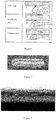
- edge defects are caused mainly because, in the horizontal rolling and vertical rolling of the rough rolling, the upper and lower edges on the side face of the slab are respectively flipped to the upper and lower surfaces (as shown in Figure 1 ).
- edges of the slab have the minimum temperature and formed defects after being rolled and flipped to the surface of the silicon steel. Due to the low temperature of the edges, they are inconsistent with their surrounding structures in deformation resistance and thus lead to cracks in the rolling extension, and defects are formed along the rolling direction in the subsequent rolling due to the failure for welding.
- the metal of the edges of the slab is in the two-phase zone in the rough rolling, and given that the deformation stress of ferrite is 1/4 lower than that of austenite phase and that deformation is concentrated in the ferrite phase, it may easily increase local deformation in the subsequent rolling process and lead to the final fracture thereby forming defects of the ferrite phase.
- the improvement of the edge quality of the hot-rolled silicon steel only involves the heating procedure and rough rolling procedure and has no special limitation on the finishing rolling procedure, and the finishing rolling procedure in the present manufacturing method of the hot-rolled silicon steel may be adopted.
- the heating procedure is conducted in the heating furnace and has no special limitation on the heating furnace; the walking beam heating furnace commonly used in the manufacturing method of the hot-rolled silicon steel may be adopted; the nozzle type may be conventional nozzle or regenerative nozzle.
- the heating furnace of the hot-rolled silicon steel is generally divided into preheating section, heating section and soaking section.
- preheating section heating section
- soaking section for some new-type hot rolling heating furnace, such strict division as above is not adopted (like pulse-type heating furnace), and the said various sections of the present invention are defined on the basis of the following principles:
- the heating characteristics of the existing heating system lies in that the preheating section has a relatively lower temperature while the heating section has a relatively higher temperature, and that the temperature of the soaking section is equivalent to the tapping temperature, so that the heat absorbed by the slab in the heating section will continuously conducted to the core to achieve the object of uniform distribution of the cross-sectional temperature of the slab.
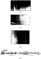
- the specific type of silicon steel manufactured by such heating system has a very high occurrence rate of edge seam defect, and exceeding to 80% in some cases, in which case edge cutting is needed to eliminate such defects.
- the aim is to achieve the cross-sectional temperature distribution of the slab as shown in Figure 2 , i.e., achieving a relatively high surface temperature of the slab, particularly achieving a relatively high edge temperature of the slab, with the following three specific purposes:
- the soaking section satisfies the following formula (2-1) or (2-2), ⁇ 10 ° C ⁇ T S ⁇ 30 ° C 2 ⁇ 1 , when the silicon content of the silicon steel is 1.5 wt% or above, 10 ° C ⁇ T S ⁇ 80 ° C 2 ⁇ 2 , when the silicon content of the silicon steel is less than 1.5 wt%, wherein,
- the heating temperature of other sections must be increased to offset the influence of the reduced temperature of the heating section on heat absorption by the slab.
- the preheating section satisfies the following formula (1), V Tp > 220 min t ⁇ 100 ° C T C + 200 ° C ⁇ 25 ° C / min wherein,
- Reducing the temperature of the heating section can prevent the overburning of the edges of the slab and avoid the linear defect caused by the above cause (3); meanwhile, given that the oxidation process is accelerated at a high heating temperature and that the ingredients of the oxides are also changed due to the rise of temperature, a layered iron skin may easily be formed and difficult to be removed when the slab is taken out of the furnace; thus, reducing the temperature of the heating section may also avoid the edge seam defect caused by the above cause (4).
- the temperature of heating section is determined by the actual production.
- the temperature of the furnace gas in the heating section is determined on the basis of the temperature rise of the heating section as calculated above in combination with the actual production pace (moving forward rate of the slab inside the furnace).
- Side reduction refers to the actual width reduction caused by the deformation force received by the slab in the width direction.
- the deformation force here may come from the vertical roll or from the slab sizing press.
- Side reduction by vertical rolling refers to the actual reduction of the slab by the vertical roll, i.e., width reduction of the slab after going through the vertical roll.
- Individual reduction refers to the width reduction of the slab after going through the vertical roll each time.
- Horizontal reduction refers to the deformation of the slab caused by the pressure imposed by the horizontal roller.
- Accumulated reduction rate refers to the ratio (%) of the outlet thickness of the slab at the end of rolling to its inlet thickness at the beginning of rolling.
- SSP side reduction refers to the width reduction of the slab after reduction by SSP.
- the rough rolling equipment commonly used in the existing manufacturing method of the hot-rolled silicon steel may be adopted in the rough rolling procedure.
- the two-roller rolling mill or four-roller rolling mill may be adopted as the rough rolling equipment.
- the parameters commonly applied at present may be used as a reference. However, if some parameters of the rough rolling procedure are set as provided below, the occurrence rate of edge defects of the hot-rolled silicon steel may be further reduced.
- 1 ⁇ 6 passes of side reduction by vertical rolling is/are applied, wherein a reduction for each side reduction is 10 ⁇ 40cm; preferably three passes of side reduction by vertical rolling are applied, with the individual reduction amounting to 30cm;
- the number of passes of water used in the rough rolling zone is controlled below 4 from taking out of the slab from the heating furnace to the intermediate roller bed.
- the rough rolling should proceed quickly, and the period between the time when the entire slab is just taken out of the furnace and the time when the final pass of the rough rolling is completed is controlled within 360s.
- SSP may be used in the rough rolling procedure as needed. Using the SSP module with a concave outline helps to reduce the distance from the edge defects to the edges; thus, the amount of edge cutting in the subsequent procedure may be reduced to increase the yield. If SSP is used, its side reduction is required to be controlled within the range of 10 ⁇ 180cm.
- improving the edge quality of the hot-rolled silicon steel does not involve the improvement of the finishing rolling procedure, so it has no special limitation on the finishing rolling procedure, and the finishing rolling equipment commonly used in the manufacturing method of the hot-rolled silicon steel at present may be adopted, i.e., generally 5 ⁇ 7-rack four-roller rolling mill.
- the hot-rolled silicon steel of the present invention can be coiled into hot-rolled silicon steel coils as needed, i.e. silicon steel coils.
- the silicon steel slab A (with a silicon content of 2.1% by weight) successively goes through the following procedures to manufacture the hot-rolled silicon steel.
- the slabs in the examples 1 ⁇ 5 respectively enters into the heating furnace to successively go through the three-section heating procedure (i.e., preheating section, heating section and soaking section) before taken out of the furnace.
- the three-section heating procedure i.e., preheating section, heating section and soaking section
- Table 1 set the side reduction, the horizontal reduction, the number of passes of water used in the rough rolling zone in the descaling water step and the rough rolling time, and send the silicon steel slabs after the heating procedure into the rough rolling equipment for rough rolling.
- the example 5 uses the slab sizing press, which is not used in the examples 1 ⁇ 4.
- Threading speed 9 ⁇ 11m/s
- target thickness 2.0 ⁇ 2.6mm.
- the hot-rolled silicon steel is then determined as unqualified.
- Defect occurrence rate Amount of unqualified silicon steel / Amount of produced silicon steel coils ⁇ % Table 1: Examples 1 2 3 4 5 Temperature of the entire slab when entering into the furnace 288 268 285 272 283 Heating procedure Preheating section Increasing rate of temperature V Tp (°C/min) 8 5 5 8 8 Heating section Temperature rise (°C) 310 466 499 294 311 Soaking section Temperature rise (°C) 10 10 - 10 30 10 Total retention time of the slab in the heating furnace (min) 221 218 215 217 218 Temperature of the entire slab upon being taken out of the furnace (°C) 1120 1120 1120 1120 1120 Rough rolling proceed ure Individual reduction (cm) 10 20 40 20 30 Side reduction by vertical rolling (pass(es)) 1 3 4 6 3 Rough rolling time (s) 210 210 210 200 200 SSP - - - - Yes Evaluat ion Occurrence rate
- the silicon steel slab A (with a silicon content of 2.1% by weight) used in the examples 1 ⁇ 5 is also used in the examples 6 ⁇ 10, and except that the rough rolling procedure is conducted as provided in Table 2, all the procedures adopted for manufacturing the silicon steel are the same as those adopted in the examples 1 ⁇ 5.
- the silicon steel slab B (with a silicon content of 0.5% by weight) is used in the examples 11 ⁇ 15, and except that the heating procedure is conducted as provided in Table 3, all the procedures adopted for manufacturing the silicon steel are the same as those adopted in the examples 1 ⁇ 5, and the same evaluation method as that adopted in the examples 1 ⁇ 5 is adopted to evaluate the occurrence rate of edge defects in the examples 11 ⁇ 15.
- the heating method and rough rolling method of the present invention can also be applied to control the occurrence rate of edge defects at a relatively low level.
- the comparative examples 1 ⁇ 3 adopt the silicon steel slab A (with a silicon content of 2.1% by weight), and the comparative examples 4 ⁇ 5 adopt the silicon steel slab B (with a silicon content of 0.5% by weight); the comparative examples 1 ⁇ 5 respectively conduct their heating procedure and rough rolling procedure based on the parameters provided in Table 4, and other than that, they adopt the same procedures as those adopted in the examples 1 ⁇ 5 to manufacture the silicon steel and employ the same evaluation method as that adopted in the examples 1 ⁇ 5 to evaluate the occurrence rate of edge defects.
- the occurrence rate of edge defects of the hot-rolled silicon steel products manufactured by the present manufacturing methods i.e., the comparative examples 1 ⁇ 5
- the occurrence rate of edge defects of the hot-rolled silicon steel products manufactured by the present manufacturing methods are respectively 11%, 8%, 7%, 8% and 6%, which are obviously higher than the occurrence rate of edge defects of the hot-rolled silicon steel products in the examples 1 ⁇ 15 of the present invention.
- the heating procedure of the present invention can obviously reduce the occurrence rate of edge defects, and simultaneously adopting the heating procedure and rough rolling procedure of the present invention can further reduce the occurrence rate of edge defects.
- the ideal choice is adopt the heating procedure and rough rolling procedure of the present invention simultaneously.
- the manufacturing method of the present invention can effectively reduce the occurrence rate of edge defects of the hot-rolled silicon steel and produce the hot-rolled silicon steel with a high surface quality, so it can be extensively applied in the manufacture of hot-rolled silicon steel coils.
Applications Claiming Priority (2)
| Application Number | Priority Date | Filing Date | Title |
|---|---|---|---|
| CN201210065610.0A CN103302104B (zh) | 2012-03-13 | 2012-03-13 | 热轧硅钢的制造方法 |
| PCT/CN2012/000401 WO2013134897A1 (zh) | 2012-03-13 | 2012-03-29 | 热轧硅钢的制造方法 |
Publications (3)
| Publication Number | Publication Date |
|---|---|
| EP2826871A1 EP2826871A1 (en) | 2015-01-21 |
| EP2826871A4 EP2826871A4 (en) | 2015-11-18 |
| EP2826871B1 true EP2826871B1 (en) | 2018-10-17 |
Family
ID=49128073
Family Applications (1)
| Application Number | Title | Priority Date | Filing Date |
|---|---|---|---|
| EP12871183.5A Active EP2826871B1 (en) | 2012-03-13 | 2012-03-29 | Hot rolled silicon steel producing method |
Country Status (9)
| Country | Link |
|---|---|
| US (1) | US9496078B2 (ko) |
| EP (1) | EP2826871B1 (ko) |
| JP (1) | JP6283617B2 (ko) |
| KR (1) | KR101609174B1 (ko) |
| CN (1) | CN103302104B (ko) |
| IN (1) | IN2014MN01793A (ko) |
| MX (1) | MX357221B (ko) |
| RU (1) | RU2591788C2 (ko) |
| WO (1) | WO2013134897A1 (ko) |
Families Citing this family (20)
| Publication number | Priority date | Publication date | Assignee | Title |
|---|---|---|---|---|
| CN103551398B (zh) * | 2013-11-06 | 2015-09-30 | 北京首钢股份有限公司 | 一种无取向硅钢热轧卷楔形控制方法 |
| CN105200441A (zh) * | 2014-05-30 | 2015-12-30 | 宝山钢铁股份有限公司 | 带氧化物层的热镀产品、其制造方法及其应用 |
| JP6748375B2 (ja) | 2016-10-19 | 2020-09-02 | Jfeスチール株式会社 | Si含有熱延鋼板の脱スケール方法 |
| CN108237148B (zh) * | 2017-10-16 | 2019-10-08 | 首钢集团有限公司 | 一种用于消除目标钢毛刺链缺陷的方法 |
| CN108246812B (zh) * | 2017-12-22 | 2019-06-04 | 包头钢铁(集团)有限责任公司 | 一种热轧钢板边部翘皮的控制方法 |
| CN109513753B (zh) * | 2018-10-10 | 2020-12-11 | 北京首钢股份有限公司 | 测试板坯角部金属流动性的方法 |
| KR20210153033A (ko) | 2019-04-20 | 2021-12-16 | 타타 스틸 이즈무이덴 베.뷔. | 강 스트립의 제조 방법 및 이에 의해 제조된 강 스트립 |
| CN110055391A (zh) * | 2019-04-24 | 2019-07-26 | 首钢集团有限公司 | 一种消除精冲钢热卷边部裂纹缺陷的方法 |
| CN110180895B (zh) * | 2019-05-28 | 2021-05-14 | 北京首钢股份有限公司 | 一种解决热轧高碳合金钢边部线状缺陷的方法 |
| CN111349778B (zh) * | 2020-03-20 | 2021-12-21 | 首钢京唐钢铁联合有限责任公司 | 一种板坯装炉间距的控制方法及装置 |
| CN111443666B (zh) * | 2020-03-25 | 2022-08-09 | 唐山钢铁集团有限责任公司 | 一种基于数据库模型的钢卷质量判定参数智能跟踪的方法 |
| CN112296102B (zh) * | 2020-09-30 | 2022-08-19 | 首钢集团有限公司 | 无取向硅钢板坯低温加热的控制方法及控制装置 |
| CN112575156A (zh) * | 2020-11-06 | 2021-03-30 | 邢台钢铁有限责任公司 | 一种改善中碳合金钢铸坯偏析的开坯方法 |
| CN112605122B (zh) * | 2020-12-15 | 2023-01-10 | 首钢智新迁安电磁材料有限公司 | 一种改善硅钢热轧板边部质量的加工方法 |
| CN113198866B (zh) * | 2021-05-07 | 2023-03-17 | 新余钢铁股份有限公司 | 一种薄规格中高牌号无取向硅钢酸轧生产工艺 |
| CN113393753B (zh) * | 2021-05-24 | 2022-08-16 | 攀钢集团攀枝花钢钒有限公司 | 钢轨半万能轧制金属流动平面演示控制方法 |
| CN113539653B (zh) * | 2021-09-16 | 2021-12-10 | 西安钢研功能材料股份有限公司 | 一种软磁合金棒材的制备方法 |
| CN114472518B (zh) * | 2021-12-24 | 2023-12-29 | 安阳钢铁股份有限公司 | 一种提高热连轧无取向硅钢厚度精度的方法 |
| CN114535315B (zh) * | 2022-02-08 | 2023-10-20 | 山西太钢不锈钢股份有限公司 | 一种防止高磁感取向硅钢热轧边裂工艺 |
| CN114632818B (zh) * | 2022-03-14 | 2023-12-05 | 安阳钢铁股份有限公司 | 一种减少取向硅钢热轧边裂的工艺方法 |
Family Cites Families (14)
| Publication number | Priority date | Publication date | Assignee | Title |
|---|---|---|---|---|
| US4204891A (en) * | 1978-11-27 | 1980-05-27 | Nippon Steel Corporation | Method for preventing the edge crack in a grain oriented silicon steel sheet produced from a continuously cast steel slab |
| JPS61243118A (ja) | 1985-04-18 | 1986-10-29 | Sumitomo Metal Ind Ltd | 2相ステンレス鋼熱間圧延鋼帯の製造方法 |
| DE69324801T2 (de) | 1992-12-28 | 1999-09-16 | Kawasaki Steel Co | Verfahren zur herstellung warmgewalzter siliziumstahlbleche mit hervorragenden oberflächeneigenschaften |
| KR100273094B1 (ko) * | 1996-06-17 | 2000-12-01 | 이구택 | 열연판의 에지크랙을 감소시키는 방향성 전기강판의 슬라브 가열방법 |
| JPH11123404A (ja) * | 1997-10-23 | 1999-05-11 | Nippon Steel Corp | 形鋼製造用矩形鋼片の加熱方法並びに形鋼の粗圧延方法 |
| RU2133283C1 (ru) * | 1998-07-06 | 1999-07-20 | Открытое акционерное общество Верхнесалдинское металлургическое производственное объединение | Способ нагрева слитков |
| KR100419641B1 (ko) * | 1999-04-15 | 2004-02-25 | 주식회사 포스코 | 방향성 전기강판의 열연판 엣지크랙 방지방법 |
| CN1258608C (zh) * | 2003-10-27 | 2006-06-07 | 宝山钢铁股份有限公司 | 冷轧无取向电工钢的制造方法 |
| JP2005152953A (ja) * | 2003-11-26 | 2005-06-16 | Jfe Steel Kk | 高シリコン鋼材の先端反り抑制方法 |
| CN100467625C (zh) * | 2005-10-31 | 2009-03-11 | 宝山钢铁股份有限公司 | 一种生产取向硅钢的方法 |
| CN100535168C (zh) * | 2007-02-16 | 2009-09-02 | 宝山钢铁股份有限公司 | 一种热轧铁素体不锈钢带钢的生产方法 |
| CN101607266A (zh) * | 2009-07-20 | 2009-12-23 | 山东泰山钢铁集团有限公司 | 一种适用于炉卷轧机生产铁素体不锈钢热轧钢带的方法 |
| RU2403293C1 (ru) * | 2009-08-03 | 2010-11-10 | Открытое акционерное общество "Новолипецкий металлургический комбинат" | Способ производства анизотропной электротехнической стали |
| CN101947549A (zh) * | 2010-09-10 | 2011-01-19 | 山东泰山钢铁集团有限公司 | 一种抑制节镍奥氏体不锈钢热轧板边裂的生产工艺 |
-
2012
- 2012-03-13 CN CN201210065610.0A patent/CN103302104B/zh active Active
- 2012-03-29 KR KR1020147025196A patent/KR101609174B1/ko active IP Right Grant
- 2012-03-29 EP EP12871183.5A patent/EP2826871B1/en active Active
- 2012-03-29 JP JP2014561247A patent/JP6283617B2/ja active Active
- 2012-03-29 WO PCT/CN2012/000401 patent/WO2013134897A1/zh active Application Filing
- 2012-03-29 IN IN1793MUN2014 patent/IN2014MN01793A/en unknown
- 2012-03-29 MX MX2014010516A patent/MX357221B/es active IP Right Grant
- 2012-03-29 US US14/372,689 patent/US9496078B2/en active Active
- 2012-03-29 RU RU2014132737/02A patent/RU2591788C2/ru active
Also Published As
| Publication number | Publication date |
|---|---|
| KR20140131952A (ko) | 2014-11-14 |
| EP2826871A4 (en) | 2015-11-18 |
| KR101609174B1 (ko) | 2016-04-05 |
| JP6283617B2 (ja) | 2018-02-21 |
| CN103302104A (zh) | 2013-09-18 |
| CN103302104B (zh) | 2015-07-22 |
| IN2014MN01793A (ko) | 2015-07-03 |
| JP2015511533A (ja) | 2015-04-20 |
| US20150243418A1 (en) | 2015-08-27 |
| MX2014010516A (es) | 2014-10-14 |
| MX357221B (es) | 2018-06-29 |
| EP2826871A1 (en) | 2015-01-21 |
| RU2591788C2 (ru) | 2016-07-20 |
| RU2014132737A (ru) | 2016-05-10 |
| WO2013134897A1 (zh) | 2013-09-19 |
| US9496078B2 (en) | 2016-11-15 |
Similar Documents
| Publication | Publication Date | Title |
|---|---|---|
| EP2826871B1 (en) | Hot rolled silicon steel producing method | |
| EP2982777B1 (en) | Titanium slab for hot rolling and method for manufacturing same | |
| CN104525560B (zh) | 普碳钢/含Nb钢20‑30mm中厚板麻面的有效控制方法 | |
| KR101516910B1 (ko) | 열간 압연 중간 슬라브의 선두부 및 후미부 절단량을 감소시키기 위한 연속 주조 슬라브의 선두부 및 후미부의 형태를 선-콘트롤하는 방법 | |
| CN104525588B (zh) | 一种提高厚规格钢板热轧过程变形渗透性的方法 | |
| CN109465295B (zh) | 一种防止热连轧钢板在冷轧中边裂断带的方法 | |
| CN102699028A (zh) | 热轧低碳钢边部线状缺陷的消除方法 | |
| KR101759915B1 (ko) | 금속 스트립 제조 방법 | |
| CN104511484A (zh) | 一种热轧带钢微中浪板形控制方法 | |
| CN111922078B (zh) | 一种屈服强度≥370MPa级的高强度厚规格钢板的生产方法 | |
| CN104117541A (zh) | 一种热轧马氏体不锈钢带钢横向翘曲控制方法 | |
| CN109772898A (zh) | 消除热连轧带钢边部翘皮缺陷的方法及该方法生产的带钢 | |
| CN103506383B (zh) | 超纯铁素体不锈钢热轧制造方法 | |
| CN110449465B (zh) | 一种降低高淬透性冷轧高强钢冷轧边裂断带的方法 | |
| CN103801580B (zh) | 一种兼顾板形的镀锌全硬板冷轧边裂控制方法 | |
| CN106048300B (zh) | 一种镍黄铜带及其制备方法 | |
| KR101795871B1 (ko) | 쌍롤식 박판 주조기를 이용한 고Cu 스테인리스강의 제조방법 | |
| CN104946872B (zh) | 一种制备钢板厚度在8~20mm的低应力热轧高强钢的方法 | |
| CN104475450B (zh) | 一种旋压坩埚用宽幅钼板带的轧制方法 | |
| CN108687132A (zh) | 一种改善金属板坯厚度分布的轧制方法及其装置 | |
| KR101220700B1 (ko) | 열간압연공정에서 중탄강 후물재 에지부 크랙 감소 방법 | |
| CN112605132B (zh) | 控制不锈钢带钢边直裂的轧制方法 | |
| CN109465294A (zh) | 一种锆板冷轧加工方法 | |
| CN102962251A (zh) | 防止低碳低硅无取向电工钢中间坯边部尖角缺陷的工艺 | |
| JP5907352B2 (ja) | 鋼スラブの熱間圧延方法 |
Legal Events
| Date | Code | Title | Description |
|---|---|---|---|
| PUAI | Public reference made under article 153(3) epc to a published international application that has entered the european phase |
Free format text: ORIGINAL CODE: 0009012 |
|
| 17P | Request for examination filed |
Effective date: 20140904 |
|
| AK | Designated contracting states |
Kind code of ref document: A1 Designated state(s): AL AT BE BG CH CY CZ DE DK EE ES FI FR GB GR HR HU IE IS IT LI LT LU LV MC MK MT NL NO PL PT RO RS SE SI SK SM TR |
|
| AX | Request for extension of the european patent |
Extension state: BA ME |
|
| DAX | Request for extension of the european patent (deleted) | ||
| RA4 | Supplementary search report drawn up and despatched (corrected) |
Effective date: 20151015 |
|
| RIC1 | Information provided on ipc code assigned before grant |
Ipc: C21D 9/70 20060101ALI20151009BHEP Ipc: B21B 37/74 20060101ALI20151009BHEP Ipc: C21D 8/04 20060101ALI20151009BHEP Ipc: C21D 9/00 20060101ALI20151009BHEP Ipc: C21D 6/00 20060101ALI20151009BHEP Ipc: C21D 8/02 20060101AFI20151009BHEP |
|
| RIC1 | Information provided on ipc code assigned before grant |
Ipc: C21D 6/00 20060101ALI20180330BHEP Ipc: C21D 9/70 20060101ALI20180330BHEP Ipc: C21D 9/00 20060101ALI20180330BHEP Ipc: C21D 8/04 20060101ALI20180330BHEP Ipc: B21B 37/74 20060101ALI20180330BHEP Ipc: C21D 8/02 20060101AFI20180330BHEP |
|
| GRAP | Despatch of communication of intention to grant a patent |
Free format text: ORIGINAL CODE: EPIDOSNIGR1 |
|
| STAA | Information on the status of an ep patent application or granted ep patent |
Free format text: STATUS: GRANT OF PATENT IS INTENDED |
|
| INTG | Intention to grant announced |
Effective date: 20180518 |
|
| GRAS | Grant fee paid |
Free format text: ORIGINAL CODE: EPIDOSNIGR3 |
|
| GRAA | (expected) grant |
Free format text: ORIGINAL CODE: 0009210 |
|
| STAA | Information on the status of an ep patent application or granted ep patent |
Free format text: STATUS: THE PATENT HAS BEEN GRANTED |
|
| AK | Designated contracting states |
Kind code of ref document: B1 Designated state(s): AL AT BE BG CH CY CZ DE DK EE ES FI FR GB GR HR HU IE IS IT LI LT LU LV MC MK MT NL NO PL PT RO RS SE SI SK SM TR |
|
| REG | Reference to a national code |
Ref country code: GB Ref legal event code: FG4D |
|
| REG | Reference to a national code |
Ref country code: CH Ref legal event code: EP |
|
| REG | Reference to a national code |
Ref country code: IE Ref legal event code: FG4D |
|
| REG | Reference to a national code |
Ref country code: DE Ref legal event code: R096 Ref document number: 602012052446 Country of ref document: DE Ref country code: AT Ref legal event code: REF Ref document number: 1054105 Country of ref document: AT Kind code of ref document: T Effective date: 20181115 |
|
| REG | Reference to a national code |
Ref country code: NL Ref legal event code: MP Effective date: 20181017 |
|
| REG | Reference to a national code |
Ref country code: LT Ref legal event code: MG4D |
|
| PG25 | Lapsed in a contracting state [announced via postgrant information from national office to epo] |
Ref country code: NL Free format text: LAPSE BECAUSE OF FAILURE TO SUBMIT A TRANSLATION OF THE DESCRIPTION OR TO PAY THE FEE WITHIN THE PRESCRIBED TIME-LIMIT Effective date: 20181017 |
|
| PG25 | Lapsed in a contracting state [announced via postgrant information from national office to epo] |
Ref country code: LV Free format text: LAPSE BECAUSE OF FAILURE TO SUBMIT A TRANSLATION OF THE DESCRIPTION OR TO PAY THE FEE WITHIN THE PRESCRIBED TIME-LIMIT Effective date: 20181017 Ref country code: ES Free format text: LAPSE BECAUSE OF FAILURE TO SUBMIT A TRANSLATION OF THE DESCRIPTION OR TO PAY THE FEE WITHIN THE PRESCRIBED TIME-LIMIT Effective date: 20181017 Ref country code: HR Free format text: LAPSE BECAUSE OF FAILURE TO SUBMIT A TRANSLATION OF THE DESCRIPTION OR TO PAY THE FEE WITHIN THE PRESCRIBED TIME-LIMIT Effective date: 20181017 Ref country code: PL Free format text: LAPSE BECAUSE OF FAILURE TO SUBMIT A TRANSLATION OF THE DESCRIPTION OR TO PAY THE FEE WITHIN THE PRESCRIBED TIME-LIMIT Effective date: 20181017 Ref country code: FI Free format text: LAPSE BECAUSE OF FAILURE TO SUBMIT A TRANSLATION OF THE DESCRIPTION OR TO PAY THE FEE WITHIN THE PRESCRIBED TIME-LIMIT Effective date: 20181017 Ref country code: BG Free format text: LAPSE BECAUSE OF FAILURE TO SUBMIT A TRANSLATION OF THE DESCRIPTION OR TO PAY THE FEE WITHIN THE PRESCRIBED TIME-LIMIT Effective date: 20190117 Ref country code: NO Free format text: LAPSE BECAUSE OF FAILURE TO SUBMIT A TRANSLATION OF THE DESCRIPTION OR TO PAY THE FEE WITHIN THE PRESCRIBED TIME-LIMIT Effective date: 20190117 Ref country code: LT Free format text: LAPSE BECAUSE OF FAILURE TO SUBMIT A TRANSLATION OF THE DESCRIPTION OR TO PAY THE FEE WITHIN THE PRESCRIBED TIME-LIMIT Effective date: 20181017 Ref country code: IS Free format text: LAPSE BECAUSE OF FAILURE TO SUBMIT A TRANSLATION OF THE DESCRIPTION OR TO PAY THE FEE WITHIN THE PRESCRIBED TIME-LIMIT Effective date: 20190217 |
|
| PG25 | Lapsed in a contracting state [announced via postgrant information from national office to epo] |
Ref country code: GR Free format text: LAPSE BECAUSE OF FAILURE TO SUBMIT A TRANSLATION OF THE DESCRIPTION OR TO PAY THE FEE WITHIN THE PRESCRIBED TIME-LIMIT Effective date: 20190118 Ref country code: RS Free format text: LAPSE BECAUSE OF FAILURE TO SUBMIT A TRANSLATION OF THE DESCRIPTION OR TO PAY THE FEE WITHIN THE PRESCRIBED TIME-LIMIT Effective date: 20181017 Ref country code: PT Free format text: LAPSE BECAUSE OF FAILURE TO SUBMIT A TRANSLATION OF THE DESCRIPTION OR TO PAY THE FEE WITHIN THE PRESCRIBED TIME-LIMIT Effective date: 20190217 Ref country code: SE Free format text: LAPSE BECAUSE OF FAILURE TO SUBMIT A TRANSLATION OF THE DESCRIPTION OR TO PAY THE FEE WITHIN THE PRESCRIBED TIME-LIMIT Effective date: 20181017 Ref country code: AL Free format text: LAPSE BECAUSE OF FAILURE TO SUBMIT A TRANSLATION OF THE DESCRIPTION OR TO PAY THE FEE WITHIN THE PRESCRIBED TIME-LIMIT Effective date: 20181017 |
|
| REG | Reference to a national code |
Ref country code: DE Ref legal event code: R097 Ref document number: 602012052446 Country of ref document: DE |
|
| PG25 | Lapsed in a contracting state [announced via postgrant information from national office to epo] |
Ref country code: DK Free format text: LAPSE BECAUSE OF FAILURE TO SUBMIT A TRANSLATION OF THE DESCRIPTION OR TO PAY THE FEE WITHIN THE PRESCRIBED TIME-LIMIT Effective date: 20181017 Ref country code: CZ Free format text: LAPSE BECAUSE OF FAILURE TO SUBMIT A TRANSLATION OF THE DESCRIPTION OR TO PAY THE FEE WITHIN THE PRESCRIBED TIME-LIMIT Effective date: 20181017 |
|
| PLBE | No opposition filed within time limit |
Free format text: ORIGINAL CODE: 0009261 |
|
| STAA | Information on the status of an ep patent application or granted ep patent |
Free format text: STATUS: NO OPPOSITION FILED WITHIN TIME LIMIT |
|
| PG25 | Lapsed in a contracting state [announced via postgrant information from national office to epo] |
Ref country code: SK Free format text: LAPSE BECAUSE OF FAILURE TO SUBMIT A TRANSLATION OF THE DESCRIPTION OR TO PAY THE FEE WITHIN THE PRESCRIBED TIME-LIMIT Effective date: 20181017 Ref country code: SM Free format text: LAPSE BECAUSE OF FAILURE TO SUBMIT A TRANSLATION OF THE DESCRIPTION OR TO PAY THE FEE WITHIN THE PRESCRIBED TIME-LIMIT Effective date: 20181017 Ref country code: EE Free format text: LAPSE BECAUSE OF FAILURE TO SUBMIT A TRANSLATION OF THE DESCRIPTION OR TO PAY THE FEE WITHIN THE PRESCRIBED TIME-LIMIT Effective date: 20181017 Ref country code: RO Free format text: LAPSE BECAUSE OF FAILURE TO SUBMIT A TRANSLATION OF THE DESCRIPTION OR TO PAY THE FEE WITHIN THE PRESCRIBED TIME-LIMIT Effective date: 20181017 |
|
| 26N | No opposition filed |
Effective date: 20190718 |
|
| PG25 | Lapsed in a contracting state [announced via postgrant information from national office to epo] |
Ref country code: SI Free format text: LAPSE BECAUSE OF FAILURE TO SUBMIT A TRANSLATION OF THE DESCRIPTION OR TO PAY THE FEE WITHIN THE PRESCRIBED TIME-LIMIT Effective date: 20181017 Ref country code: MC Free format text: LAPSE BECAUSE OF FAILURE TO SUBMIT A TRANSLATION OF THE DESCRIPTION OR TO PAY THE FEE WITHIN THE PRESCRIBED TIME-LIMIT Effective date: 20181017 |
|
| REG | Reference to a national code |
Ref country code: CH Ref legal event code: PL |
|
| PG25 | Lapsed in a contracting state [announced via postgrant information from national office to epo] |
Ref country code: LU Free format text: LAPSE BECAUSE OF NON-PAYMENT OF DUE FEES Effective date: 20190329 |
|
| REG | Reference to a national code |
Ref country code: BE Ref legal event code: MM Effective date: 20190331 |
|
| PG25 | Lapsed in a contracting state [announced via postgrant information from national office to epo] |
Ref country code: LI Free format text: LAPSE BECAUSE OF NON-PAYMENT OF DUE FEES Effective date: 20190331 Ref country code: CH Free format text: LAPSE BECAUSE OF NON-PAYMENT OF DUE FEES Effective date: 20190331 Ref country code: IE Free format text: LAPSE BECAUSE OF NON-PAYMENT OF DUE FEES Effective date: 20190329 |
|
| PG25 | Lapsed in a contracting state [announced via postgrant information from national office to epo] |
Ref country code: BE Free format text: LAPSE BECAUSE OF NON-PAYMENT OF DUE FEES Effective date: 20190331 |
|
| PG25 | Lapsed in a contracting state [announced via postgrant information from national office to epo] |
Ref country code: TR Free format text: LAPSE BECAUSE OF FAILURE TO SUBMIT A TRANSLATION OF THE DESCRIPTION OR TO PAY THE FEE WITHIN THE PRESCRIBED TIME-LIMIT Effective date: 20181017 |
|
| PG25 | Lapsed in a contracting state [announced via postgrant information from national office to epo] |
Ref country code: MT Free format text: LAPSE BECAUSE OF NON-PAYMENT OF DUE FEES Effective date: 20190329 |
|
| PG25 | Lapsed in a contracting state [announced via postgrant information from national office to epo] |
Ref country code: CY Free format text: LAPSE BECAUSE OF FAILURE TO SUBMIT A TRANSLATION OF THE DESCRIPTION OR TO PAY THE FEE WITHIN THE PRESCRIBED TIME-LIMIT Effective date: 20181017 |
|
| PG25 | Lapsed in a contracting state [announced via postgrant information from national office to epo] |
Ref country code: HU Free format text: LAPSE BECAUSE OF FAILURE TO SUBMIT A TRANSLATION OF THE DESCRIPTION OR TO PAY THE FEE WITHIN THE PRESCRIBED TIME-LIMIT; INVALID AB INITIO Effective date: 20120329 |
|
| REG | Reference to a national code |
Ref country code: AT Ref legal event code: UEP Ref document number: 1054105 Country of ref document: AT Kind code of ref document: T Effective date: 20181017 |
|
| PG25 | Lapsed in a contracting state [announced via postgrant information from national office to epo] |
Ref country code: MK Free format text: LAPSE BECAUSE OF FAILURE TO SUBMIT A TRANSLATION OF THE DESCRIPTION OR TO PAY THE FEE WITHIN THE PRESCRIBED TIME-LIMIT Effective date: 20181017 |
|
| PGFP | Annual fee paid to national office [announced via postgrant information from national office to epo] |
Ref country code: FR Payment date: 20230320 Year of fee payment: 12 Ref country code: AT Payment date: 20230220 Year of fee payment: 12 |
|
| PGFP | Annual fee paid to national office [announced via postgrant information from national office to epo] |
Ref country code: IT Payment date: 20230308 Year of fee payment: 12 |
|
| P01 | Opt-out of the competence of the unified patent court (upc) registered |
Effective date: 20230515 |
|
| PGFP | Annual fee paid to national office [announced via postgrant information from national office to epo] |
Ref country code: AT Payment date: 20240222 Year of fee payment: 13 |
|
| PGFP | Annual fee paid to national office [announced via postgrant information from national office to epo] |
Ref country code: DE Payment date: 20240307 Year of fee payment: 13 Ref country code: GB Payment date: 20240325 Year of fee payment: 13 |