EP2826692A2 - Zwangsbelüftungs- und Vakuum-Sicherheitsventil - Google Patents
Zwangsbelüftungs- und Vakuum-Sicherheitsventil Download PDFInfo
- Publication number
- EP2826692A2 EP2826692A2 EP14175524.9A EP14175524A EP2826692A2 EP 2826692 A2 EP2826692 A2 EP 2826692A2 EP 14175524 A EP14175524 A EP 14175524A EP 2826692 A2 EP2826692 A2 EP 2826692A2
- Authority
- EP
- European Patent Office
- Prior art keywords
- valve
- housing
- tank
- connection
- valve according
- Prior art date
- Legal status (The legal status is an assumption and is not a legal conclusion. Google has not performed a legal analysis and makes no representation as to the accuracy of the status listed.)
- Granted
Links
Images



Classifications
-
- F—MECHANICAL ENGINEERING; LIGHTING; HEATING; WEAPONS; BLASTING
- F16—ENGINEERING ELEMENTS AND UNITS; GENERAL MEASURES FOR PRODUCING AND MAINTAINING EFFECTIVE FUNCTIONING OF MACHINES OR INSTALLATIONS; THERMAL INSULATION IN GENERAL
- F16K—VALVES; TAPS; COCKS; ACTUATING-FLOATS; DEVICES FOR VENTING OR AERATING
- F16K15/00—Check valves
- F16K15/18—Check valves with actuating mechanism; Combined check valves and actuated valves
-
- B—PERFORMING OPERATIONS; TRANSPORTING
- B61—RAILWAYS
- B61D—BODY DETAILS OR KINDS OF RAILWAY VEHICLES
- B61D5/00—Tank wagons for carrying fluent materials
-
- F—MECHANICAL ENGINEERING; LIGHTING; HEATING; WEAPONS; BLASTING
- F16—ENGINEERING ELEMENTS AND UNITS; GENERAL MEASURES FOR PRODUCING AND MAINTAINING EFFECTIVE FUNCTIONING OF MACHINES OR INSTALLATIONS; THERMAL INSULATION IN GENERAL
- F16K—VALVES; TAPS; COCKS; ACTUATING-FLOATS; DEVICES FOR VENTING OR AERATING
- F16K17/00—Safety valves; Equalising valves, e.g. pressure relief valves
- F16K17/02—Safety valves; Equalising valves, e.g. pressure relief valves opening on surplus pressure on one side; closing on insufficient pressure on one side
- F16K17/04—Safety valves; Equalising valves, e.g. pressure relief valves opening on surplus pressure on one side; closing on insufficient pressure on one side spring-loaded
-
- F—MECHANICAL ENGINEERING; LIGHTING; HEATING; WEAPONS; BLASTING
- F16—ENGINEERING ELEMENTS AND UNITS; GENERAL MEASURES FOR PRODUCING AND MAINTAINING EFFECTIVE FUNCTIONING OF MACHINES OR INSTALLATIONS; THERMAL INSULATION IN GENERAL
- F16K—VALVES; TAPS; COCKS; ACTUATING-FLOATS; DEVICES FOR VENTING OR AERATING
- F16K27/00—Construction of housing; Use of materials therefor
- F16K27/02—Construction of housing; Use of materials therefor of lift valves
-
- F—MECHANICAL ENGINEERING; LIGHTING; HEATING; WEAPONS; BLASTING
- F16—ENGINEERING ELEMENTS AND UNITS; GENERAL MEASURES FOR PRODUCING AND MAINTAINING EFFECTIVE FUNCTIONING OF MACHINES OR INSTALLATIONS; THERMAL INSULATION IN GENERAL
- F16K—VALVES; TAPS; COCKS; ACTUATING-FLOATS; DEVICES FOR VENTING OR AERATING
- F16K27/00—Construction of housing; Use of materials therefor
- F16K27/07—Construction of housing; Use of materials therefor of cutting-off parts of tanks, e.g. tank-cars
-
- F—MECHANICAL ENGINEERING; LIGHTING; HEATING; WEAPONS; BLASTING
- F16—ENGINEERING ELEMENTS AND UNITS; GENERAL MEASURES FOR PRODUCING AND MAINTAINING EFFECTIVE FUNCTIONING OF MACHINES OR INSTALLATIONS; THERMAL INSULATION IN GENERAL
- F16K—VALVES; TAPS; COCKS; ACTUATING-FLOATS; DEVICES FOR VENTING OR AERATING
- F16K51/00—Other details not peculiar to particular types of valves or cut-off apparatus
- F16K51/02—Other details not peculiar to particular types of valves or cut-off apparatus specially adapted for high-vacuum installations
Definitions
- the invention relates to a forced ventilation and vacuum safety valve for a tank for the transport of dangerous goods according to the features of the first claim.
- the invention can be used anywhere where forced ventilation valves and vacuum safety valves are attached to a tank for the transport of dangerous goods in accordance with the European Agreement on the International Carriage of Dangerous Goods by Rail and Road (REDADR) and the Regulations on the International Carriage of Dangerous Goods by Rail (RID) be used.
- Tanks in particular tanks for tank cars, in which dangerous goods are transported, have a forced ventilation valve and a vacuum safety valve.
- the object of a vacuum safety valve is to release at an overpressure or a negative pressure in a tank or tank car, an opening through which at a negative pressure gas can escape into a tank or tank car.
- Forced ventilation valves in tanks of tank cars or tank cars are provided so that air can flow into the tank car or tank car by opening the valve at a negative pressure in the tank car or tank car.
- a valve can be arranged in a lower region of the tank, through the opening of which the dangerous material can flow out of the tank.
- This valve can be connected to a forced venting valve at the top of the tank, for example by means of a cable pull, so that when the outlet valve is opened on the tank, the forced venting valve is opened so that there is no negative pressure in the tank.
- Another possibility is to empty the tank or tank car tank with a standpipe, through which the hazardous material is sucked.
- the forced ventilation valve is usually not opened, so that when a negative pressure arises, the vacuum safety valve opens, so that air can flow into the tank, where then negative pressure is reduced.
- the negative pressure in the tank may be after existing Regulations should not be less than 0.21 bar.
- the vacuum safety valves are adjusted to this pressure. An adjustment to the valve body is not possible in conventional vacuum safety valves in a simple manner.
- a device for quick exhaust is arranged on the valve, it can only be actuated from one side.
- the actuation of other side usually requires a reversal of the valve or the attachment of another holder.
- the solution according to the invention provides a valve which combines the forced air valve with a vacuum safety valve for a tank or tank car for the transport of dangerous goods.
- the forced ventilation and vacuum safety valve consists of a molded housing with a connection for a vapor return line and another opening in the lower part of the housing through which air can enter the tank when a given vacuum is reached.
- the cast case is up with a lid closed, wherein between the lid and the housing, a seal is arranged.
- the closure of the housing with the lid is required so that it can be opened, so that setting of the release pressure on a mechanism provided in the housing can take place.
- the valve has a connection flange.
- valve disc having a stem slidably mounted on a guide, the guide being secured in the housing.
- the guide may have a screw thread with which it is screwed into the housing.
- Other types of attachment are conceivable.
- the housing may have on a bottom a partition in which the guide is attached.
- an adjustable pressure piece is arranged at the upper end of the guide, which is a straight bolt.
- the pressure piece can represent a round metal disc.
- a compression spring is arranged between the adjustable pressure piece and the underside of the housing, which can form a partition wall, which acts between the partition and the adjustable pressure piece and presses with its force the valve plate from below against the housing and the housing of the valve in this manner keeps closed against the force of the spring.
- an adjusting mechanism is arranged at the upper end of the valve stem. This can be advantageously a screw thread with a nut and a lock nut. With these nuts, the pressure piece against the force of the compression spring can be screwed down, so that the spring force is increased, which has an increase in the release pressure result.
- z. B two guide rings arranged. These can be piston guide rings, which ensure that the shaft of the valve with low friction of the valve is movable up or down.
- This connection can be a cohesive connection such as a welded or soldered connection.
- a web is arranged, to which an operation for a forced ventilation can be connected.
- a holder is arranged on the housing.
- This holder can be cast or arranged in a positive or other connection to the housing. It serves to arrange an operation of the forced ventilation at the valve.
- two opposing holders are arranged on the housing, so that the actuation can be arranged so that one end of the actuation in each case both sides - left or right - can act.
- an actuator is arranged on the web of the valve disk, which constitutes a lever which has a hole approximately at its center, through which it is movably connected to the web via a bolt, a screw, an axle o. ⁇ is.
- the actuator has at its two ends openings, wherein the one opening via a bolt, a screw or the like is connected to the holder on the housing and the opening at the other end of the operation with a cable. This cable or other actuation mechanism serves to manually or otherwise pull down the valve disc against the force of the spring to open the valve.
- connection for the gas displacement line is guided in a substantially horizontal direction in relation to the shaft in the housing and has an oval or conical shape in the region of the shaft.
- the flange or the tube of the terminal of the housing has a round shape at its end.
- the pipe of the connection of the housing With the pipe of the connection of the housing, the gas displacement line can be screwed.
- the length of the tube in the housing for connecting the gas displacement line is greater than the outer diameter of the tube of the housing. This has the advantage that the bridge has dimensions that allow easy and disability-free connection of the gas displacement line.
- connection flange of the housing is designed for the connection of the gas displacement line in the connection flange of the housing lowered.
- the circumference of the connection flange has a gap, d. H. a segment is missing.
- the fasteners on the circumference of the connection flange are accordingly to be arranged so that this is irrelevant for the attachment and tightness of the connection.
- fasteners As screws, arranged at the connection flange at the connection for the gas displacement line so that a simple assembly is possible.
- the solution according to the invention has the advantage that the functions of a forced ventilation valve and a vacuum safety valve are carried out on a tank or a tank car from a single valve, wherein the trigger point of the vacuum safety valve can be easily adjusted quickly and safely, an operation for the forced ventilation can be variably arranged on the valve and a gas displacement line can be easily and safely attached to the connection of the valve, wherein leaks between the shaft and the valve plate can not occur and the valve has a lower weight and a lower overall height.
- FIG. 1 shows a view of the valve according to the invention from above with the housing 1, which is cast and has holes in the connection flange 20 to be attached to the boiler.
- the housing 1 is closed with a cover 12 by means of screws 18.
- the housing 1 has a pipe 15 for connection to a gas displacement line, wherein the outer diameter of the tube 15 extends to the gas displacement line, wherein the connection flange 20 in the region of the tube 15 for the connecting flange of the gas displacement line is missing a circle segment, so that freedom of assembly on the connection flange 20 on the tube 15 for the gas displacement line is formed.
- the holes for the screws for fixing the flange 20 are arranged accordingly. By this arrangement, the height of the valve is reduced.
- FIG. 1 the cut lines for representations AA and BB ( FIG. 2 . 3 ).
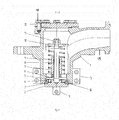
- FIG. 2 shows the section AA according to FIG. 1 in a schematic representation with the housing 1 and arranged in the upper part of tube 15 for connection to the gas displacement line, the structurally better from the other parts of the Valve is kept free.
- the molded housing 1 is closed at the top with a cover 12 which is fastened by means of screws 18 to the housing 1, wherein between the housing 1 and cover 12, a seal is arranged. After removing the lid 12, it is possible to adjust the screws 18 over the pressure piece 10 against the force of the spring 9, so that a desired force of the spring 9 is adjustable.
- the housing 1 has an opening in which a valve seat 14 is arranged, in which the valve plate 2 is located, which has the seal 3 and is pulled by the spring 9 against the valve seat 14 and the valve in this way closes.
- the valve plate 2 is welded to the shaft 6.
- the shaft 6 is guided by the guide 7, which is screwed in the lower part of the housing 1.
- the seal 3 on the valve plate 2 is interchangeable and is held by a ring nut 4, which is fixed against self-rotation by stud bolts 5.
- the distance b serves as a parameter for setting the valve.
- FIG. 3 shows the section BB according to FIG. 1 through the pipe 15 for connection to the gas displacement line, which can be seen with four holes for connection of the gas displacement line and an oval cross-section of the connection in the sectional plane.
- FIG. 4 shows the view C according to FIG. 1 showing the shape of the housing 1 below the tube 15 for the connection for the gas displacement line.
- a holder 13 is arranged on both sides, which cooperates with the web 16 on the valve plate 2.
- the left holder 13 is connected to the actuator 17, so that the valve is to be actuated from the right.
- the actuator 17 should be connected to the right side and the right holder 13.
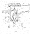
- the interaction is the FIG. 5 to see that shows an operation 17 with a cable 19. If the cable 19 is pulled on the actuator 19, over this the valve cover 2 can be opened against the force of the spring 9, which is required when a valve to open the tank or boiler is opened and a vacuum by emptying the tank or boiler is created.
Landscapes
- Engineering & Computer Science (AREA)
- General Engineering & Computer Science (AREA)
- Mechanical Engineering (AREA)
- Transportation (AREA)
- Valve Housings (AREA)
- Self-Closing Valves And Venting Or Aerating Valves (AREA)
- Filling Or Discharging Of Gas Storage Vessels (AREA)
- Safety Valves (AREA)
Abstract
Description
- Die Erfindung betrifft ein Zwangsbelüftungs- und Vakuum-Sicherheitsventil für einen Tank für die Beförderung gefährlicher Güter nach den Merkmalen des ersten Patentanspruches.
- Die Erfindung ist überall dort einsetzbar, wo Zwangsbelüftungsventile und Vakuum-Sicherheitsventile an einem Tank für die Beförderung gefährlicher Güter gemäß des Europäischen Übereinkommens über die internationale Beförderung gefährlicher Güter auf Schienen und Straßen (REDADR) und der Ordnung über die internationale Eisenbahnbeförderung gefährlicher Güter (RID) eingesetzt werden. Tanks, insbesondere Tanks für Kesselwagen, in denen gefährliche Güter transportiert werden, weisen ein Zwangsbelüftungsventil und ein Vakuum-Sicherheitsventil auf. Die Aufgabe eines Vakuum-Sicherheitsventils ist es, bei einem Über- oder einem Unterdruck in einem Tank- oder Kesselwagen eine Öffnung freizugeben, durch die bei einem Unterdruck Gas in einen Tank-oder Kesselwagen austreten kann.
- Zwangsbelüftungsventile in Tanks von Tank- oder Kesselwagen sind vorhanden, damit bei einem Unterdruck im Tank- oder Kesselwagen durch Öffnen des Ventils mittels einer Betätigung Luft in den Tank- oder Kesselwagen strömen kann.
- Damit gefährliche Güter durch das Ventil am Tank- oder Kesselwagen nicht in die Umgebung austreten können, müssen diese mittels eines Anschlusses an eine Gaspendelleitung anschließbar sein, durch die die gefährlichen Güter aus dem Tank- oder Kesselwagen entweichen und entsorgt werden können.
- Das Entleeren von Tanks von Tank- oder Kesselwagen kann auf unterschiedliche Weise erfolgen. Zum einen kann in einem unteren Bereich des Tanks ein Ventil angeordnet sein, durch dessen Öffnung das gefährliche Gut aus dem Tank abfließen kann. Dieses Ventil kann mit einem Zwangsentlüftungsventil an der Oberseite des Tanks, beispielsweise mittels Seilzuges, verbunden sein, so dass beim Öffnen des Auslassventils am Tank das Zwangsbelüftungsventil geöffnet wird, so dass kein Unterdruck im Tank entsteht.
- Eine andere Möglichkeit besteht darin, den Tank des Tank- oder Kesselwagen mit einem Steigrohr zu entleeren, durch das das gefährliche Gut abgesaugt wird. In diesem Fall wird in der Regel das Zwangsbelüftungsventil nicht geöffnet, so dass sich bei einem entstehenden Unterdruck das Vakuum-Sicherheitsventil öffnet, so dass Luft in den Tank fließen kann, wo dann Unterdruck abgebaut wird. Der Unterdruck im Tank darf nach bestehenden Vorschriften nicht weniger als 0,21 bar betragen. Auf diesen Druck werden die Vakuum-Sicherheitsventile eingestellt. Ein Verstellen am Ventilkörper ist bei herkömmlichen Vakuum-Sicherheitsventilen auf einfache Weise nicht möglich.
- Die derzeitig nach dem Stand der Technik bekannten Zwangsentlüftungs- und Vakuum-Sicherheitsventile weisen den Nachteil auf, dass diese aus Gehäusen bestehen, die aus Einzelteilen zusammengeschweißt werden. Bei der derzeitig bekannten Bauweise verläuft der Ventiltellerschaft durch den Ventilteller und erfordert eine besondere Dichtung, da sonst das Ventil Undichtheiten aufweist. Weiterhin sind die Ventile nicht problemlos exakt auf einen gewünschten Überdruck einstell- und umstellbar. Darüber hinaus bestehen Probleme, die Gaspendelleitung schnell und günstig an das Ventil anzuschließen. Weiterhin weisen die bekannten Ventile eine erhebliche Bauhöhe über dem Tank auf.
- Sofern am Ventil eine Vorrichtung zur Schnellentlüftung angeordnet ist, kann diese nur von einer Seite betätigt werden. Das Betätigen von anderer Seite erfordert in der Regel ein Umdrehen des Ventils bzw. das Anbringen eines weiteren Halters.
- Ausgehend von diesem Stand der Technik ist es Aufgabe der Erfindung, ein Ventil mit geringerer Bauhöhe zu entwickeln, welches einfach auf einen vorgegebenen Druck ein- und umgestellt werden kann, unkompliziert und sicher an eine Gaspendelleitung anschließbar ist, wobei die Fertigung und der Zusammenbau des Ventils einfach sein soll, und eine Betätigung für eine Zwangsentlüftung so anbringbar sein soll, dass das Ventil von beiden Seiten - links und rechts - betätigbar ist.
- Diese Aufgabe wird durch ein Zwangsbelüftungs- und Vakuum-Sicherheitsventil für einen Tank nach den Merkmalen des ersten Patentanspruches gelöst.
- Unteransprüche geben vorteilhafte Ausgestaltungen der Erfindung wieder.
- Die erfindungsgemäße Lösung sieht ein Ventil vor, welches das Zwangsbelüftungsventil mit einem Vakuum-Sicherheitsventil für einen Tank- oder Kesselwagen für die Beförderung gefährlicher Güter kombiniert.
- Das Zwangsbelüftungs- und Vakuum-Sicherheitsventil besteht aus einem gegossenen Gehäuse mit einem Anschluss für eine Gaspendelleitung und einer weiteren Öffnung im unteren Teil des Gehäuses, durch welches Luft in den Tank eindringen kann, wenn ein vorgegebenes Vakuum erreicht ist. Das gegossene Gehäuse ist nach oben mit einem Deckel verschlossen, wobei zwischen dem Deckel und dem Gehäuse eine Dichtung angeordnet ist. Das Verschließen des Gehäuses mit dem Deckel ist erforderlich, damit dieses geöffnet werden kann, so dass ein Einstellen des Auslösedruckes an einem dafür vorgesehenen Mechanismus im Gehäuse stattfinden kann.
Um das Ventil mit Befestigungsmitteln wie Schrauben am Tank oder einem Kessel zu befestigen und damit den Tank zu verschließen, weist das Ventil einen Anschlussflansch auf. - Nach unten wird die nach unten angeordnete Öffnung im Gehäuse durch einen Ventilteller verschlossen, der einen Schaft aufweist, der an einer Führung verschiebbar befestigt ist, wobei die Führung im Gehäuse befestigt ist.
- In vorteilhafter Weise kann die Führung ein Schraubengewinde aufweisen, mit dem diese in das Gehäuse eingeschraubt ist. Andere Befestigungsarten sind denkbar.
- Das Gehäuse kann an einer Unterseite eine Trennwand aufweisen, in der die Führung befestigt ist. Am oberen Ende der Führung, welche einen geraden Bolzen darstellt, ist ein verstellbares Druckstück angeordnet. Das Druckstück kann eine runde Metallscheibe darstellen. Zwischen dem verstellbaren Druckstück und der Unterseite des Gehäuses, die eine Trennwand bilden kann, ist eine Druckfeder angeordnet, die zwischen der Trennwand und dem verstellbaren Druckstück wirkt und mit ihrer Kraft den Ventilteller von unten gegen das Gehäuse drückt und das Gehäuse des Ventils auf diese Weise gegen die Kraft der Feder geschlossen hält. Am oberen Ende des Ventilschaftes ist ein Verstellmechanismus angeordnet. Das kann in vorteilhafter Weise ein Schraubengewinde mit einer Mutter und einer Kontermutter sein. Mit diesen Muttern kann das Druckstück gegen die Kraft der Druckfeder nach unten geschraubt werden, so dass die Federkraft erhöht wird, was eine Erhöhung des Auslösedruckes zur Folge hat.
- Zwischen der Führung und dem Schaft des Ventils sind in vorteilhafter Weise Führungsringe, z. B. zwei Führungsringe, angeordnet. Dabei kann es sich um Kolbführungsringe handeln, die dafür sorgen, dass der Schaft des Ventils mit geringer Reibung des Ventils nach oben oder unten bewegbar ist.
- Schaft des Ventils und Ventilteller sind miteinander verbunden. Diese Verbindung kann eine stoffschlüssige Verbindung wie eine Schweiß- oder Lötverbindung darstellen.
- Am Ventilteller ist ein Steg angeordnet, an den eine Betätigung für eine Zwangsentlüftung angeschlossen werden kann.
- Weiterhin ist am Gehäuse ein Halter angeordnet. Dieser Halter kann angegossen oder in einer formschlüssigen oder einer anderen Verbindung am Gehäuse angeordnet sein. Er dient dazu, eine Betätigung der Zwangsentlüftung am Ventil anzuordnen. In vorteilhafter Weise sind zwei sich gegenüberliegende Halter am Gehäuse angeordnet, so dass die Betätigung so angeordnet werden kann, dass ein Ende der Betätigung in jeweils beide Seiten - links oder rechts - wirken kann.
- Um die Zwangsentlüftung zu betätigen ist am Steg des Ventiltellers eine Betätigung angeordnet, die einen Hebel darstellt, der in etwa in seiner Mitte ein Loch aufweist, durch das er beweglich mit dem Steg über einen Bolzen, eine Schraube, eine Achse o. ä. verbunden ist. Die Betätigung weist an ihren beiden Enden Öffnungen auf, wobei die eine Öffnung über einen Bolzen, eine Schraube oder ähnliches mit dem Halter am Gehäuse verbunden ist und die Öffnung am anderen Ende der Betätigung mit einem Seilzug. Dieser Seilzug oder ein anderer Betätigungsmechanismus dient dazu, den Ventilteller gegen die Kraft der Feder manuell oder auf andere Weise nach unten zu ziehen, um damit das Ventil zu öffnen.
- Der Anschluss für die Gaspendelleitung wird gegenüber dem Schaft im Gehäuse in im Wesentlichen waagerechter Richtung geführt und weist im Bereich des Schaftes eine ovale oder konische Form auf. Der Flansch oder das Rohr des Anschlusses des Gehäuses weist an seinem Ende eine runde Form auf. Mit dem Rohr des Anschlusses des Gehäuses ist die Gaspendelleitung verschraubbar. Die Länge des Rohres im Gehäuse zum Anschluss der Gaspendelleitung ist größer, als der äußere Durchmesser des Rohres des Gehäuses. Das hat den Vorteil, dass der Steg Dimensionen aufweist, die ein leichtes und behinderungsfreies Anschließen der Gaspendelleitung ermöglicht.
- Weiterhin ist das Rohr für den Anschluss der Gaspendelleitung in dem Anschlussflansch des Gehäuses abgesenkt ausgeführt. Damit weist der Umfang des Anschlussflansches eine Lücke auf, d. h. ein Segment fehlt. Die Befestigungen auf dem Umfang des Anschlussflansches sind dementsprechend so anzuordnen, dass das für die Befestigung und Dichtheit der Verbindung unerheblich ist.
- Weiterhin sind die Befestigungen, z. B. Schrauben, am Anschlussflansch am Anschluss für die Gaspendelleitung so angeordnet, dass eine einfache Montage möglich ist.
- Die erfindungsgemäße Lösung hat den Vorteil, dass die Funktionen eines Zwangsbelüftungsventils und eines Vakuum-Sicherheitsventils an einem Tank oder einem Kesselwagen von einem einzigen Ventil ausgeführt werden, wobei der Auslösepunkt des Vakuum-Sicherheitsventils auf einfache Weise schnell und sicher eingestellt werden kann, eine Betätigung für die Zwangsentlüftung variabel am Ventil anordenbar ist und eine Gaspendelleitung einfach und sicher am Anschluss des Ventils anbringbar ist, wobei Undichtigkeiten zwischen Schaft und Ventilteller nicht auftreten können und das Ventil ein geringeres Gewicht und eine geringere Bauhöhe aufweist.
- Im Folgenden wird die Erfindung an fünf Figuren und einem Ausführungsbeispiel näher erläutert. Die Figuren zeigen:
- Figur 1:
- Ansicht auf das erfindungsgemäße Ventil von oben
- Figur 2:
- Schnitt A-A gemäß
Figur 1 - Figur 3:
- Schnitt B-B gemäß
Figur 1 - Figur 4:
- Ansicht C gemäß
Figur 1 - Figur 5:
- Schnitt A-A gemäß
Figur 1 mit einer Betätigung. - Die
Figur 1 zeigt eine Ansicht auf das erfindungsgemäße Ventil von oben mit dem Gehäuse 1, welches gegossen ist und Bohrungen im Anschlussflansch 20 aufweist, um am Kessel befestigt zu werden. Das Gehäuse 1 ist mit einem Deckel 12 mittels Schrauben 18 verschlossen. Unterhalb des Deckels 12 weist das Gehäuse 1 ein Rohr 15 für den Anschluss für eine Gaspendelleitung auf, wobei sich der Außendurchmesser des Rohres 15 zur Gaspendelleitung hin erweitert, wobei dem Anschlussflansch 20 im Bereich des Rohrs 15 für den Anschlussflansch der Gaspendelleitung ein Kreissegment fehlt, so dass Montagefreiheit am Anschlussflansch 20 am Rohr 15 für die Gaspendelleitung entsteht. - Die Löcher für die Schrauben zum Befestigen des Flansches 20 sind entsprechend angeordnet. Durch diese Anordnung wird die Bauhöhe des Ventils reduziert.
- Im Weiteren sind in die
Figur 1 die Schnittlinien für Darstellungen A-A und B-B (Figur 2 ,3 ) eingezeichnet. - Die
Figur 2 zeigt den Schnitt A-A gemäßFigur 1 in schematischer Darstellung mit dem Gehäuse 1 und dem im oberen Teil angeordneten Rohr 15 zum Anschluss zur Gaspendelleitung, die zur besseren Montierbarkeit baulich von den weiteren Teilen des Ventils freigehalten ist. Das gegossene Gehäuse 1 ist nach oben mit einem Deckel 12 verschlossen, der mittels Schrauben 18 am Gehäuse 1 befestigt ist, wobei zwischen Gehäuse 1 und Deckel 12 eine Dichtung angeordnet ist. Nach Abnehmen des Deckels 12 besteht die Möglichkeit, die Schrauben 18 über dem Druckstück 10 gegen die Kraft der Feder 9 zu verstellen, so dass eine gewünschte Kraft der Feder 9 einstellbar ist. - In seinem unteren Teil weist das Gehäuse 1 eine Öffnung auf, in der ein Ventilsitz 14 angeordnet ist, in dem sich der Ventilteller 2 befindet, der die Dichtung 3 aufweist und durch die Feder 9 gegen den Ventilsitz 14 gezogen wird und das Ventil auf diese Weise verschließt. Der Ventilteller 2 ist mit dem Schaft 6 verschweißt. Der Schaft 6 wird durch die Führung 7 geführt, die im unteren Teil des Gehäuses 1 verschraubt ist. Die Dichtung 3 am Ventilteller 2 ist auswechselbar und wird durch eine Ringmutter 4 festgehalten, die gegen Selbstdrehung durch Stiftschrauben 5 fixiert ist.
- Um ein einwandfreies Gleiten des Schaftes 6 in der Führung 7 zu ermöglichen, sind zwischen Schaft 6 und Führung 7 zwei Kolbführungsringe angeordnet. Die Vorrichtung erlaubt es, das Druckstück 10 in einem Abstand a auf dem Gewinde des Schaftes 6 mittels der Schraube 18 nach unten zu drehen. Je nachdem um welchen Betrag das Druckstück 10 auf dem Schaft 6 nach unten gedreht wird, ändert sich die Kraft, die erforderlich ist, um den Ventilteller 2 nach unten zu öffnen. Die Mutter 11 kann dann mittels einer weiteren Mutter 11 in der gewünschten Stellung gekontert, also fixiert, werden.
- Der Abstand b dient als Parameter zur Einstellung des Ventils.
- Die
Figur 3 zeigt den Schnitt B-B gemäßFigur 1 durch das Rohr 15 für den Anschluss zur Gaspendelleitung, der mit vier Bohrungen zum Anschluss der Gaspendelleitung und einem ovalen Querschnitt des Anschlusses in der Schnittebene zu sehen ist. - Die
Figur 4 zeigt die Ansicht C gemäßFigur 1 , welche die Form des Gehäuses 1 unterhalb des Rohres 15 für den Anschluss für die Gaspendelleitung darstellt. Am Gehäuse 1 ist beidseitig ein Halter 13 angeordnet, der mit dem Steg 16 am Ventilteller 2 zusammenwirkt. Im vorliegenden Fall ist der linke Halter 13 mit der Betätigung 17 verbunden, so dass das Ventil von rechts zu betätigen ist. Sollte eine Betätigung von links erforderlich sein, ist die Betätigung 17 mit der rechten Seite und dem rechten Halter 13 zu verbinden.
Das Zusammenwirken ist derFigur 5 zu entnehmen, die eine Betätigung 17 mit einem Seilzug 19 zeigt. Sofern der Seilzug 19 an der Betätigung 19 gezogen wird, kann über diese der Ventildeckel 2 gegen die Kraft der Feder 9 geöffnet werden, was dann erforderlich ist, wenn ein Ventil zum Öffnen des Tanks oder Kessels geöffnet wird und ein Unterdruck durch das Leeren das Tanks oder Kessels entsteht. -
- 1
- Gehäuse
- 2
- Ventilteller
- 3
- Dichtung
- 4
- Ringmutter
- 5
- Stiftschraube
- 6
- Schaft von 2
- 7
- Führung in 1
- 8
- Führungsring wie Kolbführungsring
- 9
- Feder wie Druckfeder
- 10
- Druckstück zwischen 9 und 11
- 11
- Mutter
- 12
- Deckel von 1
- 13
- Halter
- 14
- Ventilsitz im Gehäuse
- 15
- Rohr für den Anschluss zur Gaspendelleitung
- 16
- Steg zum Anschluss der Betätigung
- 17
- Betätigung
- 18
- Schraube
- 19
- Seilzug
- 20
- Anschlussflansch von 1
- a
- Einstellweg des Distanzstückes
- b
- Abstand als Parameter der Einstellung
Claims (11)
- Zwangsentlüftungs- und Vakuum-Sicherheitsventil für einen Tank für die Beförderung gefährlicher Güter, bestehend aus- einem gegossenen Gehäuse (1) mit einem Rohr (15) für einen Anschluss für eine Gaspendelleitung und eine untere Öffnung am Gehäuse (1),- einem Anschlussflansch (20) am Gehäuse (1) für Befestigungen am Tank,- einem Ventilteller (2) zum Verschließen der unteren Öffnung mit einem Schaft (6) in einer Führung (7) im Gehäuse (1),- einer Feder (9) zwischen einem verstellbaren Druckstück (10) und einer Innenseite des Gehäuses (1),- einem Halter (13) am Gehäuse (1) und- einem Steg (16) am Ventilteller (2).
- Ventil nach Anspruch 1, dadurch gekennzeichnet, dass zwischen dem Steg (16) am Ventilteller (2) und dem Halter (13) am Gehäuse (1) eine Betätigung (17) angeordnet ist.
- Ventil nach den Ansprüchen 1 und 2, dadurch gekennzeichnet, dass der Auslösedruck am Ventilteller mittels des Druckstückes (10) und einer Mutter (11) auf ein Gewinde des Schaftes (6) einstellbar ist.
- Ventil nach einem der Ansprüche 1 bis 3, dadurch gekennzeichnet, dass die Führung (7) in das Gehäuse (1) eingeschraubt ist.
- Ventil nach einem der Ansprüche 1 bis 4, dadurch gekennzeichnet, dass zwischen der Führung (7) und dem Schaft (6) zwei Führungsringe (8) angeordnet sind.
- Ventil nach einem der Ansprüche 1 bis 5, dadurch gekennzeichnet, dass das Gehäuse (1) oben mit einem lösbaren Deckel (12) verschlossen ist.
- Ventil nach einem der Ansprüche 1 bis 6, dadurch gekennzeichnet, dass zwischen Ventilteller (2) und Gehäuse (1) oder Ventilteller (2) und einem Ventilsitz (14) eine Dichtung (3) angeordnet ist.
- Ventil nach einem der Ansprüche 1 bis 7, dadurch gekennzeichnet, dass zwischen dem Schaft (6) und dem Ventilteller (2) einer stoffschlüssige Verbindung angeordnet ist.
- Ventil nach einem der Ansprüche 1 bis 8, dadurch gekennzeichnet, dass das Rohr (15) für den Anschluss der Gaspendelleitung im Umfang des Anschlussflansches (20) des Gehäuses (1) angeordnet ist.
- Ventil nach einem der Ansprüche 1 bis 9, dadurch gekennzeichnet, dass das Rohr (15) für den Anschluss für eine Gaspendelleitung im Querschnitt oval ausgeführt ist.
- Ventil nach einem der Ansprüche 1 bis 10, dadurch gekennzeichnet, dass am Gehäuse (1) zwei sich gegenüberliegende Halter (13) angeordnet sind.
Priority Applications (2)
| Application Number | Priority Date | Filing Date | Title |
|---|---|---|---|
| PL14175524T PL2826692T3 (pl) | 2013-07-09 | 2014-07-03 | Zawór próżniowy bezpieczeństwa i do przymusowej wentylacji |
| SI201430585T SI2826692T1 (en) | 2013-07-09 | 2014-07-03 | Forced ventilation and vacuum safety valve |
Applications Claiming Priority (1)
| Application Number | Priority Date | Filing Date | Title |
|---|---|---|---|
| DE102013213408.8A DE102013213408A1 (de) | 2013-07-09 | 2013-07-09 | Zwangsbelüftungs- und Vakuum-Sicherheitsventil für einen Tank |
Publications (3)
| Publication Number | Publication Date |
|---|---|
| EP2826692A2 true EP2826692A2 (de) | 2015-01-21 |
| EP2826692A3 EP2826692A3 (de) | 2015-02-25 |
| EP2826692B1 EP2826692B1 (de) | 2017-11-29 |
Family
ID=51257265
Family Applications (1)
| Application Number | Title | Priority Date | Filing Date |
|---|---|---|---|
| EP14175524.9A Active EP2826692B1 (de) | 2013-07-09 | 2014-07-03 | Zwangsbelüftungs- und Vakuum-Sicherheitsventil |
Country Status (6)
| Country | Link |
|---|---|
| EP (1) | EP2826692B1 (de) |
| DE (1) | DE102013213408A1 (de) |
| ES (1) | ES2658407T3 (de) |
| HU (1) | HUE038218T2 (de) |
| PL (1) | PL2826692T3 (de) |
| SI (1) | SI2826692T1 (de) |
Cited By (4)
| Publication number | Priority date | Publication date | Assignee | Title |
|---|---|---|---|---|
| DE202015103372U1 (de) | 2015-06-26 | 2015-10-05 | Waggonbau Graaff Gmbh | Bodenventil für einen Kesselwagen |
| DE202015007993U1 (de) | 2015-11-18 | 2015-12-17 | Waggonbau Graaff Gmbh | Ventilgehäuse für ein Belüftungsventil und Belüftungsventil |
| DE202016006303U1 (de) | 2016-10-12 | 2016-11-11 | Waggonbau Graaff Gmbh | Bodenventil mit einem Federgehäuse für einen Kesselwagen |
| CN114294238A (zh) * | 2021-12-31 | 2022-04-08 | 江苏金荣森制冷科技有限公司 | 带外开式泄压阀体的引流式恒压自吸泵 |
Family Cites Families (3)
| Publication number | Priority date | Publication date | Assignee | Title |
|---|---|---|---|---|
| FR1056247A (fr) * | 1952-01-28 | 1954-02-25 | Parisienne Du Materiel Coder S | Perfectionnements aux clapets de fond pour citerne |
| US5244181A (en) * | 1992-09-02 | 1993-09-14 | Knappco Corporation | High flow internal emergency valve |
| US6454237B1 (en) * | 2000-10-27 | 2002-09-24 | Delaware Capital Formation, Inc. | Air activated internal valve |
-
2013
- 2013-07-09 DE DE102013213408.8A patent/DE102013213408A1/de not_active Withdrawn
-
2014
- 2014-07-03 ES ES14175524.9T patent/ES2658407T3/es active Active
- 2014-07-03 PL PL14175524T patent/PL2826692T3/pl unknown
- 2014-07-03 EP EP14175524.9A patent/EP2826692B1/de active Active
- 2014-07-03 SI SI201430585T patent/SI2826692T1/en unknown
- 2014-07-03 HU HUE14175524A patent/HUE038218T2/hu unknown
Non-Patent Citations (1)
| Title |
|---|
| None |
Cited By (6)
| Publication number | Priority date | Publication date | Assignee | Title |
|---|---|---|---|---|
| DE202015103372U1 (de) | 2015-06-26 | 2015-10-05 | Waggonbau Graaff Gmbh | Bodenventil für einen Kesselwagen |
| EP3109524A1 (de) | 2015-06-26 | 2016-12-28 | Waggonbau Graaff GmbH | Bodenventil für einen kesselwagen |
| DE202015007993U1 (de) | 2015-11-18 | 2015-12-17 | Waggonbau Graaff Gmbh | Ventilgehäuse für ein Belüftungsventil und Belüftungsventil |
| EP3170769A1 (de) | 2015-11-18 | 2017-05-24 | Waggonbau Graaff GmbH | Ventilgehäuse für ein belüftungsventil und belüftungsventil |
| DE202016006303U1 (de) | 2016-10-12 | 2016-11-11 | Waggonbau Graaff Gmbh | Bodenventil mit einem Federgehäuse für einen Kesselwagen |
| CN114294238A (zh) * | 2021-12-31 | 2022-04-08 | 江苏金荣森制冷科技有限公司 | 带外开式泄压阀体的引流式恒压自吸泵 |
Also Published As
| Publication number | Publication date |
|---|---|
| DE102013213408A1 (de) | 2015-01-15 |
| ES2658407T3 (es) | 2018-03-09 |
| EP2826692B1 (de) | 2017-11-29 |
| SI2826692T1 (en) | 2018-03-30 |
| PL2826692T3 (pl) | 2018-05-30 |
| EP2826692A3 (de) | 2015-02-25 |
| HUE038218T2 (hu) | 2018-10-29 |
Similar Documents
| Publication | Publication Date | Title |
|---|---|---|
| EP2826692B1 (de) | Zwangsbelüftungs- und Vakuum-Sicherheitsventil | |
| EP2935954B1 (de) | Ventil | |
| EP3573502B1 (de) | Trinkflaschenverschluss, insbesondere für eine isolierflasche | |
| DE102010055316A1 (de) | Einrichtung zur Entlüftung und Belüftung eines Kraftstofftanks | |
| DE102010055312A1 (de) | Einrichtung zur Entlüftung und Belüftung eines Kraftstofftanks | |
| EP3170769B1 (de) | Ventilgehäuse für ein belüftungsventil und belüftungsventil | |
| EP1200281A1 (de) | Sicherheitsventil, insbesondere für eine betankungsentlüftungsleitung | |
| EP2853782B1 (de) | Schnellverschlussdeckel für einen Dom | |
| DE3507263C2 (de) | Unter Behälterdruck austauschbares Sicherheitsventil | |
| DE4446946C1 (de) | Schieberventil | |
| DE202012100881U1 (de) | Formatkreissäge | |
| EP3109524B1 (de) | Bodenventil für einen kesselwagen | |
| WO2012065715A1 (de) | Vorrichtung zum ausbringen von reifendichtmittel aus einem behälter | |
| EP3208379B1 (de) | Berieselungsvorrichtung für eine vorrichtung zur verdichtung eines untergrunds | |
| DE19517214B4 (de) | Ventil | |
| DE251404C (de) | ||
| DE1930733A1 (de) | Kugelhahn | |
| DE69931153T2 (de) | Steigrohrsicherung | |
| DE3040814A1 (de) | Einlaufschurre mit verschlussvorrichtung fuer seigerfoerderer, insbesondere wendelrutschen | |
| DE102015118699A1 (de) | Armatur mit Wartungsöffnung | |
| DE2245409A1 (de) | Zapfduese | |
| DE4415041C2 (de) | Vorrichtung zur Erzeugung einer Druckwelle | |
| DE202005003100U1 (de) | Deckel für den Dom eines ortsbeweglichen Kraftstofftanks | |
| DE543506C (de) | Ventil | |
| EP2105539B1 (de) | Spülventilanordnung und Spüleinrichtung mit einer solchen Spülventilanordnung |
Legal Events
| Date | Code | Title | Description |
|---|---|---|---|
| 17P | Request for examination filed |
Effective date: 20140703 |
|
| AK | Designated contracting states |
Kind code of ref document: A2 Designated state(s): AL AT BE BG CH CY CZ DE DK EE ES FI FR GB GR HR HU IE IS IT LI LT LU LV MC MK MT NL NO PL PT RO RS SE SI SK SM TR |
|
| AX | Request for extension of the european patent |
Extension state: BA ME |
|
| PUAI | Public reference made under article 153(3) epc to a published international application that has entered the european phase |
Free format text: ORIGINAL CODE: 0009012 |
|
| PUAL | Search report despatched |
Free format text: ORIGINAL CODE: 0009013 |
|
| AK | Designated contracting states |
Kind code of ref document: A3 Designated state(s): AL AT BE BG CH CY CZ DE DK EE ES FI FR GB GR HR HU IE IS IT LI LT LU LV MC MK MT NL NO PL PT RO RS SE SI SK SM TR |
|
| AX | Request for extension of the european patent |
Extension state: BA ME |
|
| RIC1 | Information provided on ipc code assigned before grant |
Ipc: F16K 27/07 20060101ALI20150121BHEP Ipc: F16K 17/04 20060101ALI20150121BHEP Ipc: F16K 51/02 20060101ALI20150121BHEP Ipc: B61G 11/18 20060101AFI20150121BHEP Ipc: F16K 15/18 20060101ALI20150121BHEP Ipc: F16K 27/02 20060101ALI20150121BHEP |
|
| R17P | Request for examination filed (corrected) |
Effective date: 20150821 |
|
| RBV | Designated contracting states (corrected) |
Designated state(s): AL AT BE BG CH CY CZ DE DK EE ES FI FR GB GR HR HU IE IS IT LI LT LU LV MC MK MT NL NO PL PT RO RS SE SI SK SM TR |
|
| GRAP | Despatch of communication of intention to grant a patent |
Free format text: ORIGINAL CODE: EPIDOSNIGR1 |
|
| RIC1 | Information provided on ipc code assigned before grant |
Ipc: F16K 27/07 20060101ALI20170629BHEP Ipc: F16K 51/02 20060101ALI20170629BHEP Ipc: F16K 17/04 20060101ALI20170629BHEP Ipc: F16K 27/02 20060101ALI20170629BHEP Ipc: F16K 15/18 20060101ALI20170629BHEP Ipc: B61D 7/02 20060101ALI20170629BHEP Ipc: B61G 11/18 20060101AFI20170629BHEP |
|
| INTG | Intention to grant announced |
Effective date: 20170714 |
|
| GRAS | Grant fee paid |
Free format text: ORIGINAL CODE: EPIDOSNIGR3 |
|
| GRAA | (expected) grant |
Free format text: ORIGINAL CODE: 0009210 |
|
| AK | Designated contracting states |
Kind code of ref document: B1 Designated state(s): AL AT BE BG CH CY CZ DE DK EE ES FI FR GB GR HR HU IE IS IT LI LT LU LV MC MK MT NL NO PL PT RO RS SE SI SK SM TR |
|
| REG | Reference to a national code |
Ref country code: CH Ref legal event code: EP |
|
| REG | Reference to a national code |
Ref country code: AT Ref legal event code: REF Ref document number: 950087 Country of ref document: AT Kind code of ref document: T Effective date: 20171215 |
|
| REG | Reference to a national code |
Ref country code: IE Ref legal event code: FG4D Free format text: LANGUAGE OF EP DOCUMENT: GERMAN |
|
| REG | Reference to a national code |
Ref country code: DE Ref legal event code: R096 Ref document number: 502014006379 Country of ref document: DE |
|
| REG | Reference to a national code |
Ref country code: DE Ref legal event code: R082 Ref document number: 502014006379 Country of ref document: DE Representative=s name: ADVOPAT PATENT- UND RECHTSANWAELTE, DE |
|
| REG | Reference to a national code |
Ref country code: RO Ref legal event code: EPE |
|
| REG | Reference to a national code |
Ref country code: ES Ref legal event code: FG2A Ref document number: 2658407 Country of ref document: ES Kind code of ref document: T3 Effective date: 20180309 |
|
| REG | Reference to a national code |
Ref country code: NL Ref legal event code: MP Effective date: 20171129 |
|
| REG | Reference to a national code |
Ref country code: LT Ref legal event code: MG4D |
|
| PG25 | Lapsed in a contracting state [announced via postgrant information from national office to epo] |
Ref country code: SE Free format text: LAPSE BECAUSE OF FAILURE TO SUBMIT A TRANSLATION OF THE DESCRIPTION OR TO PAY THE FEE WITHIN THE PRESCRIBED TIME-LIMIT Effective date: 20171129 Ref country code: NO Free format text: LAPSE BECAUSE OF FAILURE TO SUBMIT A TRANSLATION OF THE DESCRIPTION OR TO PAY THE FEE WITHIN THE PRESCRIBED TIME-LIMIT Effective date: 20180228 Ref country code: LT Free format text: LAPSE BECAUSE OF FAILURE TO SUBMIT A TRANSLATION OF THE DESCRIPTION OR TO PAY THE FEE WITHIN THE PRESCRIBED TIME-LIMIT Effective date: 20171129 Ref country code: FI Free format text: LAPSE BECAUSE OF FAILURE TO SUBMIT A TRANSLATION OF THE DESCRIPTION OR TO PAY THE FEE WITHIN THE PRESCRIBED TIME-LIMIT Effective date: 20171129 |
|
| REG | Reference to a national code |
Ref country code: SK Ref legal event code: T3 Ref document number: E 26457 Country of ref document: SK |
|
| PG25 | Lapsed in a contracting state [announced via postgrant information from national office to epo] |
Ref country code: RS Free format text: LAPSE BECAUSE OF FAILURE TO SUBMIT A TRANSLATION OF THE DESCRIPTION OR TO PAY THE FEE WITHIN THE PRESCRIBED TIME-LIMIT Effective date: 20171129 Ref country code: BG Free format text: LAPSE BECAUSE OF FAILURE TO SUBMIT A TRANSLATION OF THE DESCRIPTION OR TO PAY THE FEE WITHIN THE PRESCRIBED TIME-LIMIT Effective date: 20180228 Ref country code: HR Free format text: LAPSE BECAUSE OF FAILURE TO SUBMIT A TRANSLATION OF THE DESCRIPTION OR TO PAY THE FEE WITHIN THE PRESCRIBED TIME-LIMIT Effective date: 20171129 Ref country code: LV Free format text: LAPSE BECAUSE OF FAILURE TO SUBMIT A TRANSLATION OF THE DESCRIPTION OR TO PAY THE FEE WITHIN THE PRESCRIBED TIME-LIMIT Effective date: 20171129 Ref country code: GR Free format text: LAPSE BECAUSE OF FAILURE TO SUBMIT A TRANSLATION OF THE DESCRIPTION OR TO PAY THE FEE WITHIN THE PRESCRIBED TIME-LIMIT Effective date: 20180301 |
|
| PG25 | Lapsed in a contracting state [announced via postgrant information from national office to epo] |
Ref country code: NL Free format text: LAPSE BECAUSE OF FAILURE TO SUBMIT A TRANSLATION OF THE DESCRIPTION OR TO PAY THE FEE WITHIN THE PRESCRIBED TIME-LIMIT Effective date: 20171129 |
|
| REG | Reference to a national code |
Ref country code: FR Ref legal event code: PLFP Year of fee payment: 5 |
|
| PG25 | Lapsed in a contracting state [announced via postgrant information from national office to epo] |
Ref country code: DK Free format text: LAPSE BECAUSE OF FAILURE TO SUBMIT A TRANSLATION OF THE DESCRIPTION OR TO PAY THE FEE WITHIN THE PRESCRIBED TIME-LIMIT Effective date: 20171129 Ref country code: EE Free format text: LAPSE BECAUSE OF FAILURE TO SUBMIT A TRANSLATION OF THE DESCRIPTION OR TO PAY THE FEE WITHIN THE PRESCRIBED TIME-LIMIT Effective date: 20171129 Ref country code: CY Free format text: LAPSE BECAUSE OF FAILURE TO SUBMIT A TRANSLATION OF THE DESCRIPTION OR TO PAY THE FEE WITHIN THE PRESCRIBED TIME-LIMIT Effective date: 20171129 |
|
| REG | Reference to a national code |
Ref country code: DE Ref legal event code: R097 Ref document number: 502014006379 Country of ref document: DE |
|
| PG25 | Lapsed in a contracting state [announced via postgrant information from national office to epo] |
Ref country code: SM Free format text: LAPSE BECAUSE OF FAILURE TO SUBMIT A TRANSLATION OF THE DESCRIPTION OR TO PAY THE FEE WITHIN THE PRESCRIBED TIME-LIMIT Effective date: 20171129 |
|
| PG25 | Lapsed in a contracting state [announced via postgrant information from national office to epo] |
Ref country code: MT Free format text: LAPSE BECAUSE OF FAILURE TO SUBMIT A TRANSLATION OF THE DESCRIPTION OR TO PAY THE FEE WITHIN THE PRESCRIBED TIME-LIMIT Effective date: 20171129 |
|
| PLBE | No opposition filed within time limit |
Free format text: ORIGINAL CODE: 0009261 |
|
| STAA | Information on the status of an ep patent application or granted ep patent |
Free format text: STATUS: NO OPPOSITION FILED WITHIN TIME LIMIT |
|
| REG | Reference to a national code |
Ref country code: HU Ref legal event code: AG4A Ref document number: E038218 Country of ref document: HU |
|
| 26N | No opposition filed |
Effective date: 20180830 |
|
| REG | Reference to a national code |
Ref country code: CH Ref legal event code: PL |
|
| PG25 | Lapsed in a contracting state [announced via postgrant information from national office to epo] |
Ref country code: MC Free format text: LAPSE BECAUSE OF FAILURE TO SUBMIT A TRANSLATION OF THE DESCRIPTION OR TO PAY THE FEE WITHIN THE PRESCRIBED TIME-LIMIT Effective date: 20171129 Ref country code: LU Free format text: LAPSE BECAUSE OF NON-PAYMENT OF DUE FEES Effective date: 20180703 |
|
| REG | Reference to a national code |
Ref country code: IE Ref legal event code: MM4A |
|
| PG25 | Lapsed in a contracting state [announced via postgrant information from national office to epo] |
Ref country code: CH Free format text: LAPSE BECAUSE OF NON-PAYMENT OF DUE FEES Effective date: 20180731 Ref country code: IE Free format text: LAPSE BECAUSE OF NON-PAYMENT OF DUE FEES Effective date: 20180703 Ref country code: LI Free format text: LAPSE BECAUSE OF NON-PAYMENT OF DUE FEES Effective date: 20180731 |
|
| PG25 | Lapsed in a contracting state [announced via postgrant information from national office to epo] |
Ref country code: TR Free format text: LAPSE BECAUSE OF FAILURE TO SUBMIT A TRANSLATION OF THE DESCRIPTION OR TO PAY THE FEE WITHIN THE PRESCRIBED TIME-LIMIT Effective date: 20171129 |
|
| PG25 | Lapsed in a contracting state [announced via postgrant information from national office to epo] |
Ref country code: PT Free format text: LAPSE BECAUSE OF FAILURE TO SUBMIT A TRANSLATION OF THE DESCRIPTION OR TO PAY THE FEE WITHIN THE PRESCRIBED TIME-LIMIT Effective date: 20171129 |
|
| PG25 | Lapsed in a contracting state [announced via postgrant information from national office to epo] |
Ref country code: MK Free format text: LAPSE BECAUSE OF NON-PAYMENT OF DUE FEES Effective date: 20171129 |
|
| PG25 | Lapsed in a contracting state [announced via postgrant information from national office to epo] |
Ref country code: AL Free format text: LAPSE BECAUSE OF FAILURE TO SUBMIT A TRANSLATION OF THE DESCRIPTION OR TO PAY THE FEE WITHIN THE PRESCRIBED TIME-LIMIT Effective date: 20171129 Ref country code: IS Free format text: LAPSE BECAUSE OF FAILURE TO SUBMIT A TRANSLATION OF THE DESCRIPTION OR TO PAY THE FEE WITHIN THE PRESCRIBED TIME-LIMIT Effective date: 20180329 |
|
| REG | Reference to a national code |
Ref country code: AT Ref legal event code: MM01 Ref document number: 950087 Country of ref document: AT Kind code of ref document: T Effective date: 20190703 |
|
| PG25 | Lapsed in a contracting state [announced via postgrant information from national office to epo] |
Ref country code: AT Free format text: LAPSE BECAUSE OF NON-PAYMENT OF DUE FEES Effective date: 20190703 |
|
| PGFP | Annual fee paid to national office [announced via postgrant information from national office to epo] |
Ref country code: IT Payment date: 20220729 Year of fee payment: 9 |
|
| PG25 | Lapsed in a contracting state [announced via postgrant information from national office to epo] |
Ref country code: IT Free format text: LAPSE BECAUSE OF NON-PAYMENT OF DUE FEES Effective date: 20230703 |
|
| PGFP | Annual fee paid to national office [announced via postgrant information from national office to epo] |
Ref country code: RO Payment date: 20250626 Year of fee payment: 12 |
|
| PGFP | Annual fee paid to national office [announced via postgrant information from national office to epo] |
Ref country code: HU Payment date: 20250626 Year of fee payment: 12 |
|
| PGFP | Annual fee paid to national office [announced via postgrant information from national office to epo] |
Ref country code: ES Payment date: 20250819 Year of fee payment: 12 |
|
| PGFP | Annual fee paid to national office [announced via postgrant information from national office to epo] |
Ref country code: DE Payment date: 20250911 Year of fee payment: 12 |
|
| PGFP | Annual fee paid to national office [announced via postgrant information from national office to epo] |
Ref country code: BE Payment date: 20250722 Year of fee payment: 12 Ref country code: GB Payment date: 20250724 Year of fee payment: 12 |
|
| PGFP | Annual fee paid to national office [announced via postgrant information from national office to epo] |
Ref country code: FR Payment date: 20250723 Year of fee payment: 12 |
|
| PGFP | Annual fee paid to national office [announced via postgrant information from national office to epo] |
Ref country code: PL Payment date: 20260622 Year of fee payment: 13 |
|
| PGFP | Annual fee paid to national office [announced via postgrant information from national office to epo] |
Ref country code: CZ Payment date: 20260619 Year of fee payment: 13 |
|
| PGFP | Annual fee paid to national office [announced via postgrant information from national office to epo] |
Ref country code: SK Payment date: 20260629 Year of fee payment: 13 |
|
| PGFP | Annual fee paid to national office [announced via postgrant information from national office to epo] |
Ref country code: SI Payment date: 20260623 Year of fee payment: 13 |