EP2853782B1 - Schnellverschlussdeckel für einen Dom - Google Patents
Schnellverschlussdeckel für einen Dom Download PDFInfo
- Publication number
- EP2853782B1 EP2853782B1 EP14185701.1A EP14185701A EP2853782B1 EP 2853782 B1 EP2853782 B1 EP 2853782B1 EP 14185701 A EP14185701 A EP 14185701A EP 2853782 B1 EP2853782 B1 EP 2853782B1
- Authority
- EP
- European Patent Office
- Prior art keywords
- disc
- flange
- lid
- cover
- dome
- Prior art date
- Legal status (The legal status is an assumption and is not a legal conclusion. Google has not performed a legal analysis and makes no representation as to the accuracy of the status listed.)
- Not-in-force
Links
- 238000010276 construction Methods 0.000 description 1
- 230000008878 coupling Effects 0.000 description 1
- 238000010168 coupling process Methods 0.000 description 1
- 238000005859 coupling reaction Methods 0.000 description 1
- 230000002349 favourable effect Effects 0.000 description 1
- 239000007788 liquid Substances 0.000 description 1
- 230000013011 mating Effects 0.000 description 1
- 210000002105 tongue Anatomy 0.000 description 1
Images


Classifications
-
- F—MECHANICAL ENGINEERING; LIGHTING; HEATING; WEAPONS; BLASTING
- F16—ENGINEERING ELEMENTS AND UNITS; GENERAL MEASURES FOR PRODUCING AND MAINTAINING EFFECTIVE FUNCTIONING OF MACHINES OR INSTALLATIONS; THERMAL INSULATION IN GENERAL
- F16J—PISTONS; CYLINDERS; SEALINGS
- F16J13/00—Covers or similar closure members for pressure vessels in general
- F16J13/02—Detachable closure members; Means for tightening closures
- F16J13/08—Detachable closure members; Means for tightening closures attached by one or more members actuated to project behind a part or parts of the frame
-
- B—PERFORMING OPERATIONS; TRANSPORTING
- B65—CONVEYING; PACKING; STORING; HANDLING THIN OR FILAMENTARY MATERIAL
- B65D—CONTAINERS FOR STORAGE OR TRANSPORT OF ARTICLES OR MATERIALS, e.g. BAGS, BARRELS, BOTTLES, BOXES, CANS, CARTONS, CRATES, DRUMS, JARS, TANKS, HOPPERS, FORWARDING CONTAINERS; ACCESSORIES, CLOSURES, OR FITTINGS THEREFOR; PACKAGING ELEMENTS; PACKAGES
- B65D90/00—Component parts, details or accessories for large containers
- B65D90/10—Manholes; Inspection openings; Covers therefor
Definitions
- the invention relates to a quick-release lid for a dome according to the features of the first claim.
- the invention can be used anywhere where a tank is present, which has a dome, and this must be opened or closed quickly and safely. Under a tank with a dome can be a tank for a tank car to understand.
- Containers such as tanks for liquids have an opening through which they can be committed. These openings are closed by a lid.
- the lid can be easily connected by screws and nuts or screws in a thread of the container sealed to the container. An opening is then complicated, because all screws must be opened with a wrench before the lid can be opened.
- DE 1 130 751 describes a closure for a dome, wherein two opposing cams are pivotally mounted laterally on the dome in the region of a filling opening.
- the cams are connected via a pull rod in operative connection, wherein one side of the pull rod is rotatably mounted on a cam and the other end of the pull rod can be clamped by a nut on the other cam.
- tongues are pressed against the cam on the edge of the lid during rotation of the nut, so that the lid is pressed onto the filling opening.
- DE 1 224 662 describes a closure device in which a double lever is provided, which is rotatably mounted on one side of the dome. On the other side of the lever there is provided a holder for a thread and a part to be actuated by a handwheel, which also has a thread. The two threads are turned on a threaded screw, which is not rotatably attached to the dome. A rotation of the handwheel thus causes a linear movement of the holder, for example, down, so that the double lever is pressed onto a lid of the dome, which thereby applies sealingly against the filling opening.
- EP 0 260 436 describes a hydraulically actuated linkage for closing a dome.
- a plurality of links and a lid of the dome associated with the handlebars lever rod are arranged on the cathedral.
- the coupling gear is doing by a z.
- hydraulic actuator is actuated, wherein an operation leads to a pivoting of the lever rod and thus the lid.
- EP 0 617 688 describes a closure for a pressure vessel in which the pressure vessel C-shaped brackets are rotatably received.
- the lower legs of the C-shaped brackets are mounted on the pressure vessel such that the C-shaped brackets can be rotated after placing the lid so that they engage around the lid at the edge with their upper legs.
- a screw is further screwed, which projects through it and can exert a pressure on the lid by screwing, so that it is pressed against a seal on the pressure vessel.
- DE 1 953 085 describes a closure of a dome in which a threaded screw is mounted centrally on a lid of the dome.
- a handwheel is screwed with a thread, wherein the handwheel is so operatively connected with two levers that upon rotation of the handwheel by the lever pressure is exerted on the lid so that it rests sealingly on the opening of the dome.
- DE 3 516 721 describes a closure in which the lid is rotatably supported by a bearing on the dome.
- the lid has a plurality of intermediate levers which can be actuated by means of lever locks, so that the lid edge is pressed against a seal at the opening of the dome.
- WO 2011/023906 A1 is a polygonal quick release cap for a dome described with a flange on a neck on a tank, wherein the flange is arranged a hinge for a lid.
- the lid has a rotatable disc having a plurality of arms which are turned on or turned on by turning the disc into stops on the flange, the disc being centrally located in the lid on a pin .
- a planar rotatable thread, with the shutter slide from the center of the lid is guided in the direction of a stop or in the reverse direction, does not disclose the document.
- the arms of the disc snap into the stops on the flange by their circular motion at the bottom of a polygonal lid. As the arms of the disc rotate, they have no guides to guide them towards the stops. In a round cover as they occur on tank wagons or other tanks, this solution is not applicable.
- the solution according to the invention provides a closure cap for a dome, which constitutes a quick-release lid.
- This has a flange on the neck of a tank, wherein on the flange a hinge for the lid is arranged.
- the closure lid consists of a rotatable disk with a planar rotatable thread on a pin, which is arranged centrally in the lid.
- the pin has a cylindrical shape and can be closed at the top by a round plate.
- the pin is firmly connected to the lid, to which a welded joint is suitable, d. H. the pin can be welded to the lid. Other types of connection are conceivable.
- the closure slide is made in one piece and substantially straight. His leadership corresponds to this one-piece and straight shape and runs in the direction of the center of the cap to the stop. It is advantageous if the guide represents a T-slot in which the shutter slide is guided. However, other forms are also possible, such as a quadrangular, round, oval or rectangular shape. Furthermore, it is advantageous to arrange four closure slides on each lid. However, solutions are also conceivable in which three or a different number of closure slides are provided in a cover.
- the closure slide is movable from the center of the lid in the direction of the stop and vice versa and engages in the locked state in a stop.
- the shutter has one or more projections which engage in a rotatable thread of the disc.
- the surveys may be elevations in the form of teeth.
- each closure slide has an inclined plane on the side facing the stop.
- the lid is surrounded by a ring having a circumferential groove on its underside, in which there is a seal. Lid and ring can be connected to each other gas-tight, so that the lid and ring with the gasket close the dome gas-tight when the tightened locking slide act against the locks. It is advantageous to attach four stops with two screws on the flange. Furthermore, it is advantageous if the lid has a ring with a circumferential groove with a seal.
- Flange and counter flange which is a part of the tank, are by means of screw and. Connect parent connection. Overall, advantageously twelve screws and twelve nuts can be provided for a connection.
- the solution according to the invention has the advantage that a dome with a closure lid can be closed quickly, reliably and with little effort.
- FIG. 1 shows a quick release lid in a top view, in which two handles 9 are provided for rotating the disk 8, which causes four shutter slides 6 to move into four stops 7, so that the lid is closed and locked.
- the four stops 7 are screwed by means of screws 15 on the flange 1.
- hinges 14 are arranged, about the axis of the lid is hinged after the shutter slide 6, were removed by turning the disk 8 in the other direction, from the stops 7.
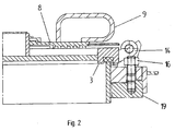
- the flange 1 is attached to the tank 19, as shown in the FIG. 2 it emerges, wherein for fastening screw 16 are arranged. A total of twelve screw 16 are arranged.
- FIG. 3 shows in a section BB of FIG. 1 how the shutter slide 6 with the disk 8 to open and close the lid 5 cooperate.
- the disc 8 is rotated about two handles 9 around the pin 11 and held on this by means of spring ring 13 and disc 12.
- the underside of the disk 8 has thread grooves into which bumps of the shutter slide 6 engage, so that upon rotation of the disk 8 in one or the other direction, the shutter slide 6 in its guide 10, which is a T-groove, inward or downward be moved outside.
- the closure slide 6 have at its end an inclined plane 17, with which they can be tightened in the stops 7, so that the ring 3 is tightened with the seal 4 against the neck 2, so that the lid 5 tight against the neck of the second is tightened on the flange 1 so that tightness exists.
- the neck 2 and the flange 1 are connected by screw 16 to the mating flange on the tank 19.
- the roof 18 is arranged, which can represent a sheet and serves as a cover on the elevations of the shutter slide 6.
Landscapes
- Engineering & Computer Science (AREA)
- General Engineering & Computer Science (AREA)
- Mechanical Engineering (AREA)
- Closures For Containers (AREA)
Description
- Die Erfindung betrifft einen Schnellverschlussdeckel für einen Dom entsprechend den Merkmalen des ersten Patentanspruches.
- Die Erfindung ist überall dort einsetzbar, wo ein Tank vorhanden ist, der einen Dom aufweist, und dieser schnell und sicher geöffnet oder geschlossen werden muss. Unter einem Tank mit einem Dom kann ein Tank für einen Kesselwagen zu verstehen sein.
- Behälter wie Tanks für Flüssigkeiten weisen eine Öffnung auf, durch die sie begangen werden können. Diese Öffnungen sind durch einen Deckel verschließbar. Der Deckel kann auf einfache Weise durch Schrauben und Muttern oder Schrauben in einem Gewinde des Behälters dicht mit dem Behälter verbunden sein. Ein Öffnen ist dann aufwendig, denn alle Schrauben sind mittels Schraubenschlüssel zu öffnen, bevor sich der Deckel öffnen lässt.
- Daher wurden unterschiedliche Lösungen entwickelt, um den Deckel schneller und einfacher öffnen zu können.
-
DE 1 130 751 beschreibt einen Verschluss für einen Dom, wobei seitlich am Dom im Bereich einer Füllöffnung zwei sich gegenüberliegende Nocken schwenkbar gelagert sind. Die Nocken stehen über eine Zugstange miteinander in Wirkverbindung, wobei eine Seite der Zugstange an einem Nocken drehbar gelagert ist und das andere Ende der Zugstange über eine Mutter am anderen Nocken eingespannt werden kann. Dadurch werden beim Zudrehen der Mutter Zungen an den Nocken auf den Rand des Deckels gedrückt, so dass der Deckel auf die Füllöffnung gedrückt wird. -
DE 1 224 662 beschreibt eine Verschlussvorrichtung, bei der ein Doppelhebel vorgesehen ist, der an einer Seite des Doms drehbar gelagert ist. An der anderen Seite des Hebels ist eine Halterung für ein Gewinde und ein von einem Handrad zu betätigendes Teil, das ebenfalls ein Gewinde aufweist, vorgesehen. Die beiden Gewinde sind auf eine Gewindeschraube aufgedreht, die nicht drehbar am Dom befestigt ist. Eine Drehung des Handrades verursacht somit eine lineare Bewegung der Halterung, beispielsweise nach unten, so dass der Doppelhebel auf einen Deckel des Doms gedrückt wird, der sich dadurch abdichtend an die Füllöffnung anlegt. -
EP 0 260 436 beschreibt ein hydraulisch betätigtes Koppelgetriebe zum Verschließen eines Doms. Dabei sind am Dom mehrere Lenker sowie an einem Deckel des Doms eine mit den Lenkern verbundene Hebelstange angeordnet. Das Koppelgetriebe wird dabei durch ein z. B. hydraulisches Stellglied betätigt, wobei eine Betätigung zu einem Verschwenken der Hebelstange und somit des Deckels führt. -
EP 0 617 688 beschreibt einen Verschluss für einen Druckbehälter, bei dem am Druckbehälter C-förmige Klammern drehbar aufgenommen sind. Die unteren Schenkel der C-förmigen Klammern sind dabei derartig am Druckbehälter gelagert, dass die C-förmigen Klammern nach dem Aufsetzen des Deckels so nach oben verdreht werden können, dass sie mit ihren oberen Schenkeln den Deckel am Rand umgreifen. In den oberen Schenkeln ist weiterhin eine Schraube eingedreht, die durch diese hindurch ragt und durch Eindrehen einen Druck auf den Deckel ausüben kann, so dass dieser gegen eine Dichtung am Druckbehälter gedrückt wird. -
DE 1 953 085 beschreibt einen Verschluss eines Doms, bei dem eine Gewindeschraube mittig auf einem Deckel des Doms befestigt ist. In die Gewindeschraube ist ein Handrad mit einem Gewinde aufgeschraubt, wobei das Handrad mit zwei Hebeln derartig in Wirkverbindung steht, dass beim Verdrehen des Handrades durch die Hebel ein Druck auf den Deckel ausgeübt wird, so dass sich dieser dichtend auf die Öffnung des Doms anlegt. -
DE 3 516 721 beschreibt einen Verschluss, bei dem der Deckel über eine Lagerung drehbar am Dom gelagert ist. Am Deckel sind mehrere Zwischenhebel angeordnet, die über Hebelverschlüsse betätigt werden können, so dass der Deckelrand an eine Dichtung an der Öffnung des Doms gedrückt wird. - Die obengenannten Lösungen sind aufgrund ihrer Bau- und Bedienweise kompliziert und störanfällig, wobei ein schnelles und einfaches Schließen und Öffnen des Deckels nicht immer möglich ist.
- In
WO.2011/023906 A1 ist ein mehreckiger Schnellverschlussdeckel für einen Dom mit einem Flansch auf einem Hals auf einem Tank beschrieben, wobei am Flansch ein Scharnier für einen Deckel angeordnet ist. Der Deckel weist eine drehbare Disk mit mehreren Armen auf, die in durch Drehen der Disk in Anschläge am Flansch ein- oder ausgeführt werden wobei die Disk an einem Zapfen mittig im Deckel angeordnet ist. Ein planares drehbares Gewinde, mit dem Verschlussschieber von der Mitte des Deckels in Richtung auf einen Anschlag oder in umgekehrter Richtung geführt wird, offenbart das Dokument nicht. Die Arme der Disk rasten durch ihre kreisförmige Bewegung an der Unterseite eines mehreckigen Deckels in die Anschläge an Flansch ein. Da die Arme der Disk sich drehen weisen sie keine Führungen auf mit denen sie in Richtung auf die Anschläge zu führen sind. Bei einem runden Deckel wie sie an Kesselwagen oder andern Tanks vorkommen, ist diese Lösung nicht anwendbar. - Ausgehend von diesem Stand der Technik ist es Aufgabe der Erfindung, eine Vorrichtung zum Verschließen und Öffnen eines runden Doms eines Behälters zu entwickeln, die schnell, sicher und einfach zu bedienen ist und den Behälter sicher verschließt.
- Diese Aufgabe wird durch eine Vorrichtung nach den Merkmalen des ersten Patentanspruches gelöst.
- Unteransprüche geben vorteilhafte Ausgestaltungen der Erfindung wieder.
- Die erfindungsgemäße Lösung sieht einen Verschlussdeckel für einen Dom vor, der einen Schnellverschlussdeckel darstellt. Dieser weist einen Flansch auf dem Hals eines Tanks auf, wobei am Flansch ein Scharnier für den Deckel angeordnet ist.
- Der Verschlussdeckel besteht aus einer drehbaren Disk mit einem planaren drehbaren Gewinde an einem Zapfen, der mittig im Deckel angeordnet ist.
- Der Zapfen weist eine zylindrische Form auf und kann nach oben durch ein rundes Blech abgeschlossen sein. Der Zapfen ist mit dem Deckel fest verbunden, wozu sich eine Schweißverbindung eignet, d. h. der Zapfen kann mit dem Deckel verschweißt sein. Andere Arten einer Verbindung sind denkbar.
- Unterhalb der Disk ist mindestens ein Verschlussschieber in einer Führung angeordnet. Der Verschlussschieber ist einteilig und im Wesentlichen gerade ausgeführt. Seine Führung entspricht dieser einteiligen und geraden Form und verläuft in Richtung vom Mittelpunkt des Verschlussdeckels zum Anschlag.
Vorteilhaft ist es, wenn die Führung eine T-Nut darstellt, in der der Verschlussschieber geführt wird. Möglich sind aber auch andere Formen wie eine viereckige, runde, ovale oder rechteckige Form. Weiterhin ist es vorteilhaft, an jedem Deckel vier Verschlussschieber anzuordnen. Denkbar sind aber auch Lösungen, bei denen in einem Deckel drei oder eine andere Anzahl von Verschlussschiebern vorgesehen sind. - Der Verschlussschieber ist von der Mitte des Deckels in Richtung auf den Anschlag und umgekehrt bewegbar und greift im verriegelten Zustand in einen Anschlag ein. Der Verschlussschieber weist eine oder mehrere Erhebungen auf, die in ein drehbares Gewinde der Disk eingreifen. Bei den Erhebungen kann es sich um Erhebungen in der Form von Zähnen handeln. Durch Drehen der Disk und das Eingreifen der Erhebungen des Verschlussschiebers in das Gewinde der Disk wird der Verschlussschieber in seiner Führung je nach Drehrichtung der Disk in Richtung auf den Mittelpunkt oder den Rand des Deckels verschoben. Um die Disk drehen zu können, sind an dieser Handgriffe angeordnet, durch die ein Bediener die Disk so lange drehen kann, bis der Verschlussschieber in die Anschläge einrastet, so dass der Deckel geschlossen ist oder aus diesen herausgezogen werden, so dass sich der Deckel öffnen lässt.
- Um ein dichtes und festes Verschließen des Deckels herbeizuführen ist es vorteilhaft, wenn zwischen Verschlussschieber und Anschlag eine schiefe Ebene angeordnet ist. Eine günstige Ausführung sieht vor, dass jeder Verschlussschieber auf der dem Anschlag zugewandten Seite eine schiefe Ebene aufweist. Durch das Hineinschieben der schiefen Ebene in jeden der Anschläge wird der Deckel fest gegen den Hals des Tanks gepresst.
- Vorteilhaft ist es weiterhin, wenn der Deckel von einem Ring umgeben ist, der eine auf seiner Unterseite umlaufende Nut aufweist, in der sich eine Dichtung befindet. Deckel und Ring können miteinander gasdicht verbunden sein, so dass Deckel und Ring mit der Dichtung den Dom gasdicht abschließen, wenn die festgezogenen Verschlussschieber gegen die Verriegelungen wirken.
Vorteilhaft ist es, vier Anschläge mit jeweils zwei Schrauben am Flansch zu befestigen. Weiterhin ist es vorteilhaft, wenn der Deckel einen Ring mit einer umlaufenden Nut mit einer Dichtung aufweist. - Weiterhin ist es vorteilhaft, die Disk mittels einer Scheibe und eines Federringes in einer Nut am Zapfen zu halten. Damit ist eine einfache Montage oder Demontage möglich.
- Darüber hinaus ist es vorteilhaft, am Flansch einen Gegenflansch anzuordnen.
- Flansch und Gegenflansch, der einen Teil des Tanks darstellt, sind mittels Schrauben- und. Mutterverbindung miteinander zu verbinden. Insgesamt können vorteilhafterweise zwölf Schrauben und zwölf Muttern für eine Verbindung vorgesehen werden.
- Die erfindungsgemäße Lösung hat den Vorteil, dass ein Dom mit einem Verschlussdeckel schnell, zuverlässig und mit geringem Aufwand verschlossen werden kann.
- Im Folgenden wird die Erfindung an einem Ausführungsbeispiel und drei Figuren näher erläutert. Die Figuren zeigen:
- Figur 1:
- Schnellverschlussdeckel für einen Dom in Ansicht von oben
- Figur 2:
- Schnitt A-A von
Figur 1 - Figur 3:
- Schnitt B-B von
Figur 1 . - Die
Figur 1 zeigt einen Schnellverschlussdeckel in einer Ansicht von oben, bei dem zwei Handgriffe 9 für das Drehen der Disk 8 vorgesehen sind, was bewirkt, dass vier Verschlussschieber 6 sich in vier Anschläge 7 hinein bewegen, so dass der Deckel verschlossen und verriegelt ist. Die vier Anschläge 7 sind mittels Schrauben 15 am Flansch 1 festgeschraubt. Zwischen dem Flansch 1 und dem Deckel 5 sind Scharniere 14 angeordnet, um deren Achse der Deckel aufklappbar ist, nachdem die Verschlussschieber 6, durch Drehen der Disk 8 in die andere Richtung, aus den Anschlägen 7 entfernt wurden. - Der Flansch 1 ist am Tank 19 befestigt, wie das aus der
Figur 2 hervorgeht, wobei zum Befestigen Schraubenverbindungen 16 angeordnet sind. Insgesamt sind dazu zwölf Schraubenverbindungen 16 angeordnet. - Die
Figur 3 zeigt in einem Schnitt B-B vonFigur 1 wie die Verschlussschieber 6 mit der Disk 8 zum Öffnen und Schließen des Deckels 5 zusammenwirken. Die Disk 8 wird über zwei Handgriffe 9 um den Zapfen 11 gedreht und an diesem mittels Federringes 13 und Scheibe 12 gehalten. Die Unterseite der Disk 8 weist Gewinderillen auf, in die Erhebungen der Verschlussschieber 6 eingreifen, so dass bei Drehen der Disk 8 in die eine oder die andere Richtung die Verschlussschieber 6 in ihrer Führung 10, die eine T-Nut darstellt, nach innen oder nach außen verschoben werden. Die Verschlussschieber 6 weisen an ihrem Ende eine schiefe Ebene 17 auf, mit der sie in den Anschlägen 7 festgezogen werden können, so dass der Ring 3 mit der Dichtung 4 gegen den Hals 2 festgezogen wird, so dass der Deckel 5 dicht gegen den Hals 2 am Flansch 1 festgezogen wird, so dass Dichtheit besteht. Der Hals 2 und der Flansch 1 sind mit Schraubverbindungen 16 mit dem Gegenflansch am Tank 19 verbunden. An der Disk 8 ist das Dach 18 angeordnet, das ein Blech darstellen kann und als Abdeckung auf den Erhebungen der Verschlussschieber 6 dient. -
- 1
- Flansch
- 2
- Hals
- 3
- Ring mit Nut
- 4
- Dichtung
- 5
- Deckel
- 6
- Verschlussschieber
- 7
- Anschlag
- 8
- Disk
- 9
- Handgriff
- 10
- Führung mit T-Nut
- 11
- Zapfen
- 12
- Scheibe
- 13
- Federring
- 14
- Scharnier
- 15
- Schraube
- 16
- Schraubverbindung
- 17
- schiefe Ebene
- 18
- Dach
- 19
- Tank
Claims (10)
- Schnellverschlussdeckel für einen Dom mit einem Flansch (1) auf einem Hals (2) an einem Tank (19), wobei am Flansch (1) ein Scharnier (14) für einen Deckel (5) angeordnet ist, bestehend aus- einer drehbaren Disk (8) mit einem planaren drehbaren Gewinde an einem Zapfen (11), der mittig im Deckel (5) angeordnet ist,- mindestens einem Verschlussschieber (6) in einer Führung (10), der im verriegelten Zustand in einen Anschlag (7) am Flansch (1) eingreift,- einer oder mehreren Erhebungen am Verschlussschieber (6), die in das drehbare Gewinde der Disk (8) eingreifen,- mindestens einem Handgriff (9) an der Disk (8) zum Drehen der Disk (8), wobei der Verschlussschieber (6) durch Drehen der Disk (8) in die Anschläge (7) ausoder eingeführt wird, dadurch gekennzeichnet, dass- die Unterseite der Disk (8) Gewinderillen aufweist, die in Erhebungen des Verschlussschiebers (6 eingreifen, so dass beim Drehen der Disk (8) der Verschlussschieber (6) in einer Führung (10) ie nach Drehrichtung auf den Mittelpunkt oder den Rand des Deckels (5) und in den Anschlag (7) verschoben wird.
- Vorrichtung nach Anspruch 1, dadurch gekennzeichnet, dass ein Ring (3) am Deckel (5) angeordnet ist, der gegen den Hals (2) wirkt.
- Vorrichtung nach den Ansprüchen 1 und 2, dadurch gekenntzeichnet, dass der Verschlussschieber (6) an seiner dem Anschlag (7) zugewandten Seite eine schiefe Ebene (17) aufweist.
- Vorrichtung nach einem der Ansprüche 1 bis 3, dadurch gekennzeichnet, dass vier Verschlussschieber (6) und vier Führungen (10) im Deckel (5) angeordnet sind.
- Vorrichtung nach einem der Ansprüche 1 bis 4, dadurch gekennzeichnet, dass die Führung (10) eine T-Nut aufweist.
- Vorrichtung nach einem der Ansprüche 1 bis 5, dadurch gekennzeichnet, dass jeder Anschlag (7) mit jeweils zwei Schrauben (15) am Flansch (1) befestigt ist.
- Vorrichtung nach einem der Ansprüche 1 bis 6, dadurch gekennzeichnet, dass der Ring (3) in einer umlaufenden Nut eine Dichtung (4) aufweist.
- Vorrichtung nach einem der Ansprüche 1 bis 7, dadurch gekennzeichnet, dass an der Disk (8) zwei Handgriffe (9) angeordnet sind.
- Vorrichtung nach einem der Ansprüche 1 bis 8, dadurch gekennzeichnet, dass die Disk (8) mittels einer Scheibe (12) und eines Federringes (13) in einer Nut des Zapfens (11) gehalten wird.
- Vorrichtung nach einem der Ansprüche 1 bis 9, dadurch gekennzeichnet, dass der Flansch (1) und ein Gegenflansch mittels Schrauben (16) und Mutterverbindung miteinander verbunden sind.
Applications Claiming Priority (1)
| Application Number | Priority Date | Filing Date | Title |
|---|---|---|---|
| DE201310219233 DE102013219233A1 (de) | 2013-09-25 | 2013-09-25 | Schnellverschlussdeckel für einen Dom |
Publications (2)
| Publication Number | Publication Date |
|---|---|
| EP2853782A1 EP2853782A1 (de) | 2015-04-01 |
| EP2853782B1 true EP2853782B1 (de) | 2016-07-13 |
Family
ID=51570407
Family Applications (1)
| Application Number | Title | Priority Date | Filing Date |
|---|---|---|---|
| EP14185701.1A Not-in-force EP2853782B1 (de) | 2013-09-25 | 2014-09-22 | Schnellverschlussdeckel für einen Dom |
Country Status (3)
| Country | Link |
|---|---|
| EP (1) | EP2853782B1 (de) |
| DE (1) | DE102013219233A1 (de) |
| PL (1) | PL2853782T3 (de) |
Families Citing this family (3)
| Publication number | Priority date | Publication date | Assignee | Title |
|---|---|---|---|---|
| CN104590787B (zh) * | 2015-01-14 | 2017-06-13 | 上海鸿研物流技术有限公司 | 容器及其锁定机构 |
| DE102016003038B3 (de) * | 2016-03-14 | 2017-05-11 | Waggonbau Graaff Gmbh | Schnellverschlussdom |
| CN109305445A (zh) * | 2018-10-22 | 2019-02-05 | 刘秀英 | 一种计算机运输储存保护防撞装置 |
Family Cites Families (14)
| Publication number | Priority date | Publication date | Assignee | Title |
|---|---|---|---|---|
| DE25957C (de) * | ||||
| US1197702A (en) * | 1914-03-28 | 1916-09-12 | Williams Foundry And Machine Company | Quick-opening head for horizontal vulcanizers. |
| US1582209A (en) * | 1924-08-25 | 1926-04-27 | Ehret Conrad | Closure for thief holes for tanks and other receptacles |
| US2533771A (en) * | 1948-07-09 | 1950-12-12 | Pennsylvania Furnace And Iron | Vented closure for milk tank manholes |
| US2818195A (en) * | 1956-09-28 | 1957-12-31 | John A Scarlett | Quick opening door |
| DE1130751B (de) | 1956-10-01 | 1962-05-30 | Linke Hofmann Busch | Verschluss fuer Behaelter, insbesondere fuer den Dom von Kesselwagen |
| BE643859A (de) | 1963-02-15 | |||
| US3531011A (en) * | 1968-12-18 | 1970-09-29 | Dixie Mfg Co Inc | Latch securing means for a container |
| DE3516721A1 (de) | 1985-05-09 | 1986-11-13 | Linke-Hofmann-Busch Waggon-Fahrzeug-Maschinen Gmbh, 3320 Salzgitter | Verschlusseinrichtung fuer behaelteroeffnungen, insbesondere fuer den dom auf schienengebundenen schuettgut- und kesselwagen |
| DE3627871A1 (de) | 1986-08-16 | 1988-02-18 | Linke Hofmann Busch | Verschlusseinrichtung fuer lade- oder entladeoeffnungen in transportkessel, insbesondere fuer schienengebundene kessel- und schuettgutwagen |
| US5275501A (en) * | 1991-12-09 | 1994-01-04 | The Pfaudler Companies, Inc. | Quick opening manhole cover assembly for use with virtually any shape manhole cover |
| CH686302A5 (de) | 1992-08-25 | 1996-02-29 | Heinz Bolli | Verschluss fuer Druckbehaelter. |
| FR2872446A1 (fr) * | 2004-07-02 | 2006-01-06 | Commissariat Energie Atomique | Dispositif de transfert etanche a double porte comportant des organes d'actionnement des portes equipes de hublots |
| FR2949599B1 (fr) * | 2009-08-26 | 2011-11-25 | Martin Bernard Saint | Dispositif de jonction temporaire etanche a double porte |
-
2013
- 2013-09-25 DE DE201310219233 patent/DE102013219233A1/de not_active Withdrawn
-
2014
- 2014-09-22 PL PL14185701T patent/PL2853782T3/pl unknown
- 2014-09-22 EP EP14185701.1A patent/EP2853782B1/de not_active Not-in-force
Also Published As
| Publication number | Publication date |
|---|---|
| DE102013219233A1 (de) | 2015-03-26 |
| PL2853782T3 (pl) | 2017-01-31 |
| EP2853782A1 (de) | 2015-04-01 |
Similar Documents
| Publication | Publication Date | Title |
|---|---|---|
| DE112017004771B4 (de) | Verschließbare Behälterabdeckung | |
| CH686302A5 (de) | Verschluss fuer Druckbehaelter. | |
| CH649513A5 (de) | Mannlochdeckelanordnung mit schnellverschluss. | |
| EP2853782B1 (de) | Schnellverschlussdeckel für einen Dom | |
| EP2957539B1 (de) | Tankbefüllsystem | |
| DE102004040928B4 (de) | Verschluss für einen Behälter | |
| DE102016003038B3 (de) | Schnellverschlussdom | |
| EP3170769B1 (de) | Ventilgehäuse für ein belüftungsventil und belüftungsventil | |
| DE102007018390B3 (de) | Kochgefäß, insbesondere Dampfdruckkochtopf | |
| DE69103838T2 (de) | Auseinandernehmbarer Behälter, der für einen internen Druck ausgelegt ist. | |
| DE2647037C2 (de) | Verschluß für Mannlöcher | |
| AT394702B (de) | Verschlusseinrichtung fuer behaelteroeffnungen, insbesondere fuer den dom auf schienengebundenen schuettgut- und kesselwagen | |
| WO2020260236A1 (de) | GEFÄßDECKEL MIT EINER WIEDERVERSCHLIEßBAREN TRINKÖFFNUNG | |
| DE817118C (de) | Spannringverschluss fuer Verpackungsgefaesse | |
| DE2252861C3 (de) | Verschlußanordnung für Öffnungen | |
| DE619997C (de) | Schraubenlose Verschlusseinrichtung fuer Druckgefaesse | |
| DE202010004206U1 (de) | Trinkflaschenverschluss | |
| CH596480A5 (en) | Rapid action closure for pressure or vacuum container | |
| EP3592679B1 (de) | Umfüllvorrichtung | |
| DE102014113437B4 (de) | Verschlusseinrichtung | |
| DE1475770B2 (de) | Autoklav zum sterilisieren mit rechteckigem querschnitt, rechteckiger verschlussoeffnung und rechteckigem verschlussdeckel | |
| DE8422173U1 (de) | Isolierkanne | |
| DE38475C (de) | Spundverschlufs für Fässer und andere Behälter | |
| DE2449010C3 (de) | Verschließbarer Behälterverschluß für Flüssigkeitsbehälter | |
| DE123646C (de) |
Legal Events
| Date | Code | Title | Description |
|---|---|---|---|
| PUAI | Public reference made under article 153(3) epc to a published international application that has entered the european phase |
Free format text: ORIGINAL CODE: 0009012 |
|
| 17P | Request for examination filed |
Effective date: 20140922 |
|
| AK | Designated contracting states |
Kind code of ref document: A1 Designated state(s): AL AT BE BG CH CY CZ DE DK EE ES FI FR GB GR HR HU IE IS IT LI LT LU LV MC MK MT NL NO PL PT RO RS SE SI SK SM TR |
|
| AX | Request for extension of the european patent |
Extension state: BA ME |
|
| R17P | Request for examination filed (corrected) |
Effective date: 20150903 |
|
| RBV | Designated contracting states (corrected) |
Designated state(s): AL AT BE BG CH CY CZ DE DK EE ES FI FR GB GR HR HU IE IS IT LI LT LU LV MC MK MT NL NO PL PT RO RS SE SI SK SM TR |
|
| GRAP | Despatch of communication of intention to grant a patent |
Free format text: ORIGINAL CODE: EPIDOSNIGR1 |
|
| INTG | Intention to grant announced |
Effective date: 20160316 |
|
| GRAS | Grant fee paid |
Free format text: ORIGINAL CODE: EPIDOSNIGR3 |
|
| GRAA | (expected) grant |
Free format text: ORIGINAL CODE: 0009210 |
|
| AK | Designated contracting states |
Kind code of ref document: B1 Designated state(s): AL AT BE BG CH CY CZ DE DK EE ES FI FR GB GR HR HU IE IS IT LI LT LU LV MC MK MT NL NO PL PT RO RS SE SI SK SM TR |
|
| REG | Reference to a national code |
Ref country code: GB Ref legal event code: FG4D Free format text: NOT ENGLISH |
|
| REG | Reference to a national code |
Ref country code: AT Ref legal event code: REF Ref document number: 812621 Country of ref document: AT Kind code of ref document: T Effective date: 20160715 Ref country code: CH Ref legal event code: EP |
|
| REG | Reference to a national code |
Ref country code: IE Ref legal event code: FG4D Free format text: LANGUAGE OF EP DOCUMENT: GERMAN |
|
| REG | Reference to a national code |
Ref country code: DE Ref legal event code: R096 Ref document number: 502014001100 Country of ref document: DE |
|
| REG | Reference to a national code |
Ref country code: FR Ref legal event code: PLFP Year of fee payment: 3 |
|
| PGFP | Annual fee paid to national office [announced via postgrant information from national office to epo] |
Ref country code: BG Payment date: 20160921 Year of fee payment: 3 Ref country code: DE Payment date: 20160818 Year of fee payment: 3 |
|
| REG | Reference to a national code |
Ref country code: LT Ref legal event code: MG4D |
|
| REG | Reference to a national code |
Ref country code: NL Ref legal event code: MP Effective date: 20160713 |
|
| PGFP | Annual fee paid to national office [announced via postgrant information from national office to epo] |
Ref country code: CZ Payment date: 20160913 Year of fee payment: 3 Ref country code: FR Payment date: 20160922 Year of fee payment: 3 |
|
| REG | Reference to a national code |
Ref country code: RO Ref legal event code: EPE |
|
| PG25 | Lapsed in a contracting state [announced via postgrant information from national office to epo] |
Ref country code: LT Free format text: LAPSE BECAUSE OF FAILURE TO SUBMIT A TRANSLATION OF THE DESCRIPTION OR TO PAY THE FEE WITHIN THE PRESCRIBED TIME-LIMIT Effective date: 20160713 Ref country code: RS Free format text: LAPSE BECAUSE OF FAILURE TO SUBMIT A TRANSLATION OF THE DESCRIPTION OR TO PAY THE FEE WITHIN THE PRESCRIBED TIME-LIMIT Effective date: 20160713 Ref country code: NL Free format text: LAPSE BECAUSE OF FAILURE TO SUBMIT A TRANSLATION OF THE DESCRIPTION OR TO PAY THE FEE WITHIN THE PRESCRIBED TIME-LIMIT Effective date: 20160713 Ref country code: IT Free format text: LAPSE BECAUSE OF FAILURE TO SUBMIT A TRANSLATION OF THE DESCRIPTION OR TO PAY THE FEE WITHIN THE PRESCRIBED TIME-LIMIT Effective date: 20160713 Ref country code: NO Free format text: LAPSE BECAUSE OF FAILURE TO SUBMIT A TRANSLATION OF THE DESCRIPTION OR TO PAY THE FEE WITHIN THE PRESCRIBED TIME-LIMIT Effective date: 20161013 Ref country code: IS Free format text: LAPSE BECAUSE OF FAILURE TO SUBMIT A TRANSLATION OF THE DESCRIPTION OR TO PAY THE FEE WITHIN THE PRESCRIBED TIME-LIMIT Effective date: 20161113 Ref country code: FI Free format text: LAPSE BECAUSE OF FAILURE TO SUBMIT A TRANSLATION OF THE DESCRIPTION OR TO PAY THE FEE WITHIN THE PRESCRIBED TIME-LIMIT Effective date: 20160713 Ref country code: HR Free format text: LAPSE BECAUSE OF FAILURE TO SUBMIT A TRANSLATION OF THE DESCRIPTION OR TO PAY THE FEE WITHIN THE PRESCRIBED TIME-LIMIT Effective date: 20160713 |
|
| PGFP | Annual fee paid to national office [announced via postgrant information from national office to epo] |
Ref country code: SK Payment date: 20160914 Year of fee payment: 3 |
|
| PG25 | Lapsed in a contracting state [announced via postgrant information from national office to epo] |
Ref country code: BE Free format text: LAPSE BECAUSE OF NON-PAYMENT OF DUE FEES Effective date: 20160930 Ref country code: PT Free format text: LAPSE BECAUSE OF FAILURE TO SUBMIT A TRANSLATION OF THE DESCRIPTION OR TO PAY THE FEE WITHIN THE PRESCRIBED TIME-LIMIT Effective date: 20161114 Ref country code: GR Free format text: LAPSE BECAUSE OF FAILURE TO SUBMIT A TRANSLATION OF THE DESCRIPTION OR TO PAY THE FEE WITHIN THE PRESCRIBED TIME-LIMIT Effective date: 20161014 Ref country code: SE Free format text: LAPSE BECAUSE OF FAILURE TO SUBMIT A TRANSLATION OF THE DESCRIPTION OR TO PAY THE FEE WITHIN THE PRESCRIBED TIME-LIMIT Effective date: 20160713 Ref country code: LV Free format text: LAPSE BECAUSE OF FAILURE TO SUBMIT A TRANSLATION OF THE DESCRIPTION OR TO PAY THE FEE WITHIN THE PRESCRIBED TIME-LIMIT Effective date: 20160713 Ref country code: ES Free format text: LAPSE BECAUSE OF FAILURE TO SUBMIT A TRANSLATION OF THE DESCRIPTION OR TO PAY THE FEE WITHIN THE PRESCRIBED TIME-LIMIT Effective date: 20160713 |
|
| PGFP | Annual fee paid to national office [announced via postgrant information from national office to epo] |
Ref country code: PL Payment date: 20160913 Year of fee payment: 3 Ref country code: RO Payment date: 20160913 Year of fee payment: 3 |
|
| REG | Reference to a national code |
Ref country code: DE Ref legal event code: R097 Ref document number: 502014001100 Country of ref document: DE |
|
| PG25 | Lapsed in a contracting state [announced via postgrant information from national office to epo] |
Ref country code: EE Free format text: LAPSE BECAUSE OF FAILURE TO SUBMIT A TRANSLATION OF THE DESCRIPTION OR TO PAY THE FEE WITHIN THE PRESCRIBED TIME-LIMIT Effective date: 20160713 Ref country code: MC Free format text: LAPSE BECAUSE OF FAILURE TO SUBMIT A TRANSLATION OF THE DESCRIPTION OR TO PAY THE FEE WITHIN THE PRESCRIBED TIME-LIMIT Effective date: 20160713 |
|
| PLBE | No opposition filed within time limit |
Free format text: ORIGINAL CODE: 0009261 |
|
| STAA | Information on the status of an ep patent application or granted ep patent |
Free format text: STATUS: NO OPPOSITION FILED WITHIN TIME LIMIT |
|
| PG25 | Lapsed in a contracting state [announced via postgrant information from national office to epo] |
Ref country code: SM Free format text: LAPSE BECAUSE OF FAILURE TO SUBMIT A TRANSLATION OF THE DESCRIPTION OR TO PAY THE FEE WITHIN THE PRESCRIBED TIME-LIMIT Effective date: 20160713 Ref country code: DK Free format text: LAPSE BECAUSE OF FAILURE TO SUBMIT A TRANSLATION OF THE DESCRIPTION OR TO PAY THE FEE WITHIN THE PRESCRIBED TIME-LIMIT Effective date: 20160713 |
|
| 26N | No opposition filed |
Effective date: 20170418 |
|
| REG | Reference to a national code |
Ref country code: IE Ref legal event code: MM4A |
|
| PG25 | Lapsed in a contracting state [announced via postgrant information from national office to epo] |
Ref country code: IE Free format text: LAPSE BECAUSE OF NON-PAYMENT OF DUE FEES Effective date: 20160922 |
|
| PG25 | Lapsed in a contracting state [announced via postgrant information from national office to epo] |
Ref country code: LU Free format text: LAPSE BECAUSE OF NON-PAYMENT OF DUE FEES Effective date: 20160922 Ref country code: SI Free format text: LAPSE BECAUSE OF FAILURE TO SUBMIT A TRANSLATION OF THE DESCRIPTION OR TO PAY THE FEE WITHIN THE PRESCRIBED TIME-LIMIT Effective date: 20160713 |
|
| REG | Reference to a national code |
Ref country code: BE Ref legal event code: MM Effective date: 20160930 |
|
| REG | Reference to a national code |
Ref country code: DE Ref legal event code: R119 Ref document number: 502014001100 Country of ref document: DE |
|
| PG25 | Lapsed in a contracting state [announced via postgrant information from national office to epo] |
Ref country code: RO Free format text: LAPSE BECAUSE OF NON-PAYMENT OF DUE FEES Effective date: 20170922 Ref country code: CZ Free format text: LAPSE BECAUSE OF NON-PAYMENT OF DUE FEES Effective date: 20170922 |
|
| REG | Reference to a national code |
Ref country code: CH Ref legal event code: PL |
|
| PG25 | Lapsed in a contracting state [announced via postgrant information from national office to epo] |
Ref country code: HU Free format text: LAPSE BECAUSE OF FAILURE TO SUBMIT A TRANSLATION OF THE DESCRIPTION OR TO PAY THE FEE WITHIN THE PRESCRIBED TIME-LIMIT; INVALID AB INITIO Effective date: 20140922 |
|
| REG | Reference to a national code |
Ref country code: SK Ref legal event code: MM4A Ref document number: E 21926 Country of ref document: SK Effective date: 20170922 |
|
| PG25 | Lapsed in a contracting state [announced via postgrant information from national office to epo] |
Ref country code: CY Free format text: LAPSE BECAUSE OF FAILURE TO SUBMIT A TRANSLATION OF THE DESCRIPTION OR TO PAY THE FEE WITHIN THE PRESCRIBED TIME-LIMIT Effective date: 20160713 Ref country code: MT Free format text: LAPSE BECAUSE OF FAILURE TO SUBMIT A TRANSLATION OF THE DESCRIPTION OR TO PAY THE FEE WITHIN THE PRESCRIBED TIME-LIMIT Effective date: 20160713 Ref country code: MK Free format text: LAPSE BECAUSE OF FAILURE TO SUBMIT A TRANSLATION OF THE DESCRIPTION OR TO PAY THE FEE WITHIN THE PRESCRIBED TIME-LIMIT Effective date: 20160713 |
|
| REG | Reference to a national code |
Ref country code: FR Ref legal event code: ST Effective date: 20180531 |
|
| PG25 | Lapsed in a contracting state [announced via postgrant information from national office to epo] |
Ref country code: DE Free format text: LAPSE BECAUSE OF NON-PAYMENT OF DUE FEES Effective date: 20180404 Ref country code: SK Free format text: LAPSE BECAUSE OF NON-PAYMENT OF DUE FEES Effective date: 20170922 Ref country code: LI Free format text: LAPSE BECAUSE OF NON-PAYMENT OF DUE FEES Effective date: 20170930 Ref country code: CH Free format text: LAPSE BECAUSE OF NON-PAYMENT OF DUE FEES Effective date: 20170930 |
|
| PG25 | Lapsed in a contracting state [announced via postgrant information from national office to epo] |
Ref country code: FR Free format text: LAPSE BECAUSE OF NON-PAYMENT OF DUE FEES Effective date: 20171002 |
|
| PG25 | Lapsed in a contracting state [announced via postgrant information from national office to epo] |
Ref country code: TR Free format text: LAPSE BECAUSE OF FAILURE TO SUBMIT A TRANSLATION OF THE DESCRIPTION OR TO PAY THE FEE WITHIN THE PRESCRIBED TIME-LIMIT Effective date: 20160713 Ref country code: AL Free format text: LAPSE BECAUSE OF FAILURE TO SUBMIT A TRANSLATION OF THE DESCRIPTION OR TO PAY THE FEE WITHIN THE PRESCRIBED TIME-LIMIT Effective date: 20160713 |
|
| GBPC | Gb: european patent ceased through non-payment of renewal fee |
Effective date: 20180922 |
|
| PG25 | Lapsed in a contracting state [announced via postgrant information from national office to epo] |
Ref country code: BG Free format text: LAPSE BECAUSE OF NON-PAYMENT OF DUE FEES Effective date: 20190430 |
|
| PG25 | Lapsed in a contracting state [announced via postgrant information from national office to epo] |
Ref country code: GB Free format text: LAPSE BECAUSE OF NON-PAYMENT OF DUE FEES Effective date: 20180922 |
|
| PG25 | Lapsed in a contracting state [announced via postgrant information from national office to epo] |
Ref country code: PL Free format text: LAPSE BECAUSE OF NON-PAYMENT OF DUE FEES Effective date: 20170922 |
|
| REG | Reference to a national code |
Ref country code: AT Ref legal event code: MM01 Ref document number: 812621 Country of ref document: AT Kind code of ref document: T Effective date: 20190922 |
|
| PG25 | Lapsed in a contracting state [announced via postgrant information from national office to epo] |
Ref country code: AT Free format text: LAPSE BECAUSE OF NON-PAYMENT OF DUE FEES Effective date: 20190922 |