EP2826083B1 - Large format electrochemical energy storage device housing and module - Google Patents
Large format electrochemical energy storage device housing and module Download PDFInfo
- Publication number
- EP2826083B1 EP2826083B1 EP13761001.0A EP13761001A EP2826083B1 EP 2826083 B1 EP2826083 B1 EP 2826083B1 EP 13761001 A EP13761001 A EP 13761001A EP 2826083 B1 EP2826083 B1 EP 2826083B1
- Authority
- EP
- European Patent Office
- Prior art keywords
- assembly
- electrochemical
- cathode
- anode
- housing
- Prior art date
- Legal status (The legal status is an assumption and is not a legal conclusion. Google has not performed a legal analysis and makes no representation as to the accuracy of the status listed.)
- Not-in-force
Links
- 238000012983 electrochemical energy storage Methods 0.000 title description 23
- 210000004027 cell Anatomy 0.000 claims description 52
- 230000000712 assembly Effects 0.000 claims description 21
- 238000000429 assembly Methods 0.000 claims description 21
- 239000000463 material Substances 0.000 claims description 13
- 210000000352 storage cell Anatomy 0.000 claims description 13
- 150000002500 ions Chemical class 0.000 claims description 7
- 238000006243 chemical reaction Methods 0.000 claims description 6
- 239000003513 alkali Substances 0.000 claims description 4
- 239000000853 adhesive Substances 0.000 claims description 3
- 230000001070 adhesive effect Effects 0.000 claims description 3
- 239000000203 mixture Substances 0.000 claims description 3
- 239000011230 binding agent Substances 0.000 claims description 2
- 238000009830 intercalation Methods 0.000 claims description 2
- 230000002687 intercalation Effects 0.000 claims 1
- 239000003792 electrolyte Substances 0.000 description 14
- 239000002253 acid Substances 0.000 description 10
- 230000006835 compression Effects 0.000 description 8
- 238000007906 compression Methods 0.000 description 8
- 239000007789 gas Substances 0.000 description 8
- -1 e.g. Chemical compound 0.000 description 7
- 238000012546 transfer Methods 0.000 description 7
- OKTJSMMVPCPJKN-UHFFFAOYSA-N Carbon Chemical compound [C] OKTJSMMVPCPJKN-UHFFFAOYSA-N 0.000 description 5
- 230000013011 mating Effects 0.000 description 5
- 239000003990 capacitor Substances 0.000 description 4
- 238000004146 energy storage Methods 0.000 description 4
- 229910052751 metal Inorganic materials 0.000 description 4
- 239000002184 metal Substances 0.000 description 4
- 230000002441 reversible effect Effects 0.000 description 4
- 238000003860 storage Methods 0.000 description 4
- 238000003466 welding Methods 0.000 description 4
- 229910000831 Steel Inorganic materials 0.000 description 3
- 239000002585 base Substances 0.000 description 3
- 238000005219 brazing Methods 0.000 description 3
- 150000001768 cations Chemical class 0.000 description 3
- 238000010586 diagram Methods 0.000 description 3
- 239000007772 electrode material Substances 0.000 description 3
- 238000005516 engineering process Methods 0.000 description 3
- 239000010439 graphite Substances 0.000 description 3
- 229910002804 graphite Inorganic materials 0.000 description 3
- 229910001416 lithium ion Inorganic materials 0.000 description 3
- 238000005192 partition Methods 0.000 description 3
- 239000010959 steel Substances 0.000 description 3
- DGAQECJNVWCQMB-PUAWFVPOSA-M Ilexoside XXIX Chemical compound C[C@@H]1CC[C@@]2(CC[C@@]3(C(=CC[C@H]4[C@]3(CC[C@@H]5[C@@]4(CC[C@@H](C5(C)C)OS(=O)(=O)[O-])C)C)[C@@H]2[C@]1(C)O)C)C(=O)O[C@H]6[C@@H]([C@H]([C@@H]([C@H](O6)CO)O)O)O.[Na+] DGAQECJNVWCQMB-PUAWFVPOSA-M 0.000 description 2
- WHXSMMKQMYFTQS-UHFFFAOYSA-N Lithium Chemical compound [Li] WHXSMMKQMYFTQS-UHFFFAOYSA-N 0.000 description 2
- 239000004743 Polypropylene Substances 0.000 description 2
- 229910052783 alkali metal Inorganic materials 0.000 description 2
- 229910052799 carbon Inorganic materials 0.000 description 2
- 239000004020 conductor Substances 0.000 description 2
- AMWRITDGCCNYAT-UHFFFAOYSA-L hydroxy(oxo)manganese;manganese Chemical compound [Mn].O[Mn]=O.O[Mn]=O AMWRITDGCCNYAT-UHFFFAOYSA-L 0.000 description 2
- 239000011244 liquid electrolyte Substances 0.000 description 2
- 238000004519 manufacturing process Methods 0.000 description 2
- 238000000034 method Methods 0.000 description 2
- 238000012986 modification Methods 0.000 description 2
- 230000004048 modification Effects 0.000 description 2
- 239000008188 pellet Substances 0.000 description 2
- 239000004033 plastic Substances 0.000 description 2
- 229920003023 plastic Polymers 0.000 description 2
- 229920001155 polypropylene Polymers 0.000 description 2
- 238000010248 power generation Methods 0.000 description 2
- 230000001012 protector Effects 0.000 description 2
- 230000003014 reinforcing effect Effects 0.000 description 2
- 239000011734 sodium Substances 0.000 description 2
- 229910001415 sodium ion Inorganic materials 0.000 description 2
- 239000007787 solid Substances 0.000 description 2
- 229910052596 spinel Inorganic materials 0.000 description 2
- 239000011029 spinel Substances 0.000 description 2
- 229910001220 stainless steel Inorganic materials 0.000 description 2
- 239000010935 stainless steel Substances 0.000 description 2
- HBBGRARXTFLTSG-UHFFFAOYSA-N Lithium ion Chemical compound [Li+] HBBGRARXTFLTSG-UHFFFAOYSA-N 0.000 description 1
- 239000004698 Polyethylene Substances 0.000 description 1
- 150000007513 acids Chemical class 0.000 description 1
- 239000010405 anode material Substances 0.000 description 1
- 238000003491 array Methods 0.000 description 1
- 230000015556 catabolic process Effects 0.000 description 1
- 230000003247 decreasing effect Effects 0.000 description 1
- 238000006731 degradation reaction Methods 0.000 description 1
- 238000013461 design Methods 0.000 description 1
- 229920001971 elastomer Polymers 0.000 description 1
- 238000003487 electrochemical reaction Methods 0.000 description 1
- 230000005518 electrochemistry Effects 0.000 description 1
- 239000000446 fuel Substances 0.000 description 1
- 238000013023 gasketing Methods 0.000 description 1
- 239000011245 gel electrolyte Substances 0.000 description 1
- 238000003306 harvesting Methods 0.000 description 1
- 230000003993 interaction Effects 0.000 description 1
- 238000005342 ion exchange Methods 0.000 description 1
- 238000005304 joining Methods 0.000 description 1
- 229910052744 lithium Inorganic materials 0.000 description 1
- 229910000625 lithium cobalt oxide Inorganic materials 0.000 description 1
- GELKBWJHTRAYNV-UHFFFAOYSA-K lithium iron phosphate Chemical compound [Li+].[Fe+2].[O-]P([O-])([O-])=O GELKBWJHTRAYNV-UHFFFAOYSA-K 0.000 description 1
- BFZPBUKRYWOWDV-UHFFFAOYSA-N lithium;oxido(oxo)cobalt Chemical compound [Li+].[O-][Co]=O BFZPBUKRYWOWDV-UHFFFAOYSA-N 0.000 description 1
- 230000007774 longterm Effects 0.000 description 1
- 229910044991 metal oxide Inorganic materials 0.000 description 1
- 150000004706 metal oxides Chemical class 0.000 description 1
- 239000011255 nonaqueous electrolyte Substances 0.000 description 1
- 238000010943 off-gassing Methods 0.000 description 1
- 238000004806 packaging method and process Methods 0.000 description 1
- 230000037361 pathway Effects 0.000 description 1
- 229920000447 polyanionic polymer Polymers 0.000 description 1
- 229920000573 polyethylene Polymers 0.000 description 1
- 229920000642 polymer Polymers 0.000 description 1
- 229920001296 polysiloxane Polymers 0.000 description 1
- 230000002062 proliferating effect Effects 0.000 description 1
- 230000001105 regulatory effect Effects 0.000 description 1
- 230000029058 respiratory gaseous exchange Effects 0.000 description 1
- 230000004044 response Effects 0.000 description 1
- 229920002379 silicone rubber Polymers 0.000 description 1
- 239000004945 silicone rubber Substances 0.000 description 1
- 238000004513 sizing Methods 0.000 description 1
- 229910052708 sodium Inorganic materials 0.000 description 1
- 229910000314 transition metal oxide Inorganic materials 0.000 description 1
- 238000013519 translation Methods 0.000 description 1
- XLYOFNOQVPJJNP-UHFFFAOYSA-N water Substances O XLYOFNOQVPJJNP-UHFFFAOYSA-N 0.000 description 1
Images


Classifications
-
- H—ELECTRICITY
- H01—ELECTRIC ELEMENTS
- H01G—CAPACITORS; CAPACITORS, RECTIFIERS, DETECTORS, SWITCHING DEVICES, LIGHT-SENSITIVE OR TEMPERATURE-SENSITIVE DEVICES OF THE ELECTROLYTIC TYPE
- H01G11/00—Hybrid capacitors, i.e. capacitors having different positive and negative electrodes; Electric double-layer [EDL] capacitors; Processes for the manufacture thereof or of parts thereof
- H01G11/04—Hybrid capacitors
- H01G11/06—Hybrid capacitors with one of the electrodes allowing ions to be reversibly doped thereinto, e.g. lithium ion capacitors [LIC]
-
- H—ELECTRICITY
- H01—ELECTRIC ELEMENTS
- H01G—CAPACITORS; CAPACITORS, RECTIFIERS, DETECTORS, SWITCHING DEVICES, LIGHT-SENSITIVE OR TEMPERATURE-SENSITIVE DEVICES OF THE ELECTROLYTIC TYPE
- H01G11/00—Hybrid capacitors, i.e. capacitors having different positive and negative electrodes; Electric double-layer [EDL] capacitors; Processes for the manufacture thereof or of parts thereof
- H01G11/10—Multiple hybrid or EDL capacitors, e.g. arrays or modules
- H01G11/12—Stacked hybrid or EDL capacitors
-
- H—ELECTRICITY
- H01—ELECTRIC ELEMENTS
- H01G—CAPACITORS; CAPACITORS, RECTIFIERS, DETECTORS, SWITCHING DEVICES, LIGHT-SENSITIVE OR TEMPERATURE-SENSITIVE DEVICES OF THE ELECTROLYTIC TYPE
- H01G11/00—Hybrid capacitors, i.e. capacitors having different positive and negative electrodes; Electric double-layer [EDL] capacitors; Processes for the manufacture thereof or of parts thereof
- H01G11/22—Electrodes
- H01G11/30—Electrodes characterised by their material
- H01G11/32—Carbon-based
-
- H—ELECTRICITY
- H01—ELECTRIC ELEMENTS
- H01G—CAPACITORS; CAPACITORS, RECTIFIERS, DETECTORS, SWITCHING DEVICES, LIGHT-SENSITIVE OR TEMPERATURE-SENSITIVE DEVICES OF THE ELECTROLYTIC TYPE
- H01G11/00—Hybrid capacitors, i.e. capacitors having different positive and negative electrodes; Electric double-layer [EDL] capacitors; Processes for the manufacture thereof or of parts thereof
- H01G11/22—Electrodes
- H01G11/30—Electrodes characterised by their material
- H01G11/46—Metal oxides
-
- H—ELECTRICITY
- H01—ELECTRIC ELEMENTS
- H01G—CAPACITORS; CAPACITORS, RECTIFIERS, DETECTORS, SWITCHING DEVICES, LIGHT-SENSITIVE OR TEMPERATURE-SENSITIVE DEVICES OF THE ELECTROLYTIC TYPE
- H01G11/00—Hybrid capacitors, i.e. capacitors having different positive and negative electrodes; Electric double-layer [EDL] capacitors; Processes for the manufacture thereof or of parts thereof
- H01G11/78—Cases; Housings; Encapsulations; Mountings
- H01G11/82—Fixing or assembling a capacitive element in a housing, e.g. mounting electrodes, current collectors or terminals in containers or encapsulations
-
- H—ELECTRICITY
- H01—ELECTRIC ELEMENTS
- H01M—PROCESSES OR MEANS, e.g. BATTERIES, FOR THE DIRECT CONVERSION OF CHEMICAL ENERGY INTO ELECTRICAL ENERGY
- H01M50/00—Constructional details or processes of manufacture of the non-active parts of electrochemical cells other than fuel cells, e.g. hybrid cells
- H01M50/20—Mountings; Secondary casings or frames; Racks, modules or packs; Suspension devices; Shock absorbers; Transport or carrying devices; Holders
- H01M50/204—Racks, modules or packs for multiple batteries or multiple cells
-
- H—ELECTRICITY
- H01—ELECTRIC ELEMENTS
- H01M—PROCESSES OR MEANS, e.g. BATTERIES, FOR THE DIRECT CONVERSION OF CHEMICAL ENERGY INTO ELECTRICAL ENERGY
- H01M50/00—Constructional details or processes of manufacture of the non-active parts of electrochemical cells other than fuel cells, e.g. hybrid cells
- H01M50/20—Mountings; Secondary casings or frames; Racks, modules or packs; Suspension devices; Shock absorbers; Transport or carrying devices; Holders
- H01M50/218—Mountings; Secondary casings or frames; Racks, modules or packs; Suspension devices; Shock absorbers; Transport or carrying devices; Holders characterised by the material
- H01M50/22—Mountings; Secondary casings or frames; Racks, modules or packs; Suspension devices; Shock absorbers; Transport or carrying devices; Holders characterised by the material of the casings or racks
- H01M50/227—Organic material
-
- H—ELECTRICITY
- H01—ELECTRIC ELEMENTS
- H01M—PROCESSES OR MEANS, e.g. BATTERIES, FOR THE DIRECT CONVERSION OF CHEMICAL ENERGY INTO ELECTRICAL ENERGY
- H01M50/00—Constructional details or processes of manufacture of the non-active parts of electrochemical cells other than fuel cells, e.g. hybrid cells
- H01M50/20—Mountings; Secondary casings or frames; Racks, modules or packs; Suspension devices; Shock absorbers; Transport or carrying devices; Holders
- H01M50/271—Lids or covers for the racks or secondary casings
-
- H—ELECTRICITY
- H01—ELECTRIC ELEMENTS
- H01M—PROCESSES OR MEANS, e.g. BATTERIES, FOR THE DIRECT CONVERSION OF CHEMICAL ENERGY INTO ELECTRICAL ENERGY
- H01M2220/00—Batteries for particular applications
- H01M2220/10—Batteries in stationary systems, e.g. emergency power source in plant
-
- Y—GENERAL TAGGING OF NEW TECHNOLOGICAL DEVELOPMENTS; GENERAL TAGGING OF CROSS-SECTIONAL TECHNOLOGIES SPANNING OVER SEVERAL SECTIONS OF THE IPC; TECHNICAL SUBJECTS COVERED BY FORMER USPC CROSS-REFERENCE ART COLLECTIONS [XRACs] AND DIGESTS
- Y02—TECHNOLOGIES OR APPLICATIONS FOR MITIGATION OR ADAPTATION AGAINST CLIMATE CHANGE
- Y02E—REDUCTION OF GREENHOUSE GAS [GHG] EMISSIONS, RELATED TO ENERGY GENERATION, TRANSMISSION OR DISTRIBUTION
- Y02E60/00—Enabling technologies; Technologies with a potential or indirect contribution to GHG emissions mitigation
- Y02E60/10—Energy storage using batteries
-
- Y—GENERAL TAGGING OF NEW TECHNOLOGICAL DEVELOPMENTS; GENERAL TAGGING OF CROSS-SECTIONAL TECHNOLOGIES SPANNING OVER SEVERAL SECTIONS OF THE IPC; TECHNICAL SUBJECTS COVERED BY FORMER USPC CROSS-REFERENCE ART COLLECTIONS [XRACs] AND DIGESTS
- Y02—TECHNOLOGIES OR APPLICATIONS FOR MITIGATION OR ADAPTATION AGAINST CLIMATE CHANGE
- Y02P—CLIMATE CHANGE MITIGATION TECHNOLOGIES IN THE PRODUCTION OR PROCESSING OF GOODS
- Y02P70/00—Climate change mitigation technologies in the production process for final industrial or consumer products
- Y02P70/50—Manufacturing or production processes characterised by the final manufactured product
-
- Y—GENERAL TAGGING OF NEW TECHNOLOGICAL DEVELOPMENTS; GENERAL TAGGING OF CROSS-SECTIONAL TECHNOLOGIES SPANNING OVER SEVERAL SECTIONS OF THE IPC; TECHNICAL SUBJECTS COVERED BY FORMER USPC CROSS-REFERENCE ART COLLECTIONS [XRACs] AND DIGESTS
- Y10—TECHNICAL SUBJECTS COVERED BY FORMER USPC
- Y10T—TECHNICAL SUBJECTS COVERED BY FORMER US CLASSIFICATION
- Y10T29/00—Metal working
- Y10T29/49—Method of mechanical manufacture
- Y10T29/49002—Electrical device making
- Y10T29/49108—Electric battery cell making
- Y10T29/49114—Electric battery cell making including adhesively bonding
Definitions
- the separator 116 includes flanges 116A around the periphery of the separator 116.
- the flanges 116A define one or more cavities that are configured to receive the anode/cathode electrode pieces 112, 114.
- the electrochemical storage cells 111 include a plurality of flexible, electrically conductive contacts (e.g., tabs) 118 operatively connected to the plurality of cathode and anode current collectors 130, 132.
- the flexible, electrically conductive contacts 118 may be affixed to one side of the cathode and anode current collectors 130, 132.
- electrical connection to the stacks 110 of electrochemical storage cells 111 in adjacent cavities 104 in the housing 102 may be made by draping the flexible, electrically conductive contacts 118 over the walls 105 between adjacent cavities 104 and connecting the stacks 110.
- the stacks 110 in adjacent cavities 104 may be electrically connected in series, in parallel or combination thereof as desired.
- the flexible, electrically conductive contacts 118 from adjacent stacks 110 are joined together 166, such as by welding or brazing.
- the electrically conductive contacts 118 of alternate cells 111 in the stack 110 of cells 111 are affixed to each other, such as by welding or brazing. That is, the electrically conductive contacts 118 connected to successive cathode electrodes 114 / cathode current collectors 130 are connected to each other while the electrically conductive contacts 118 connected to successive anode electrodes 112 / anode current collectors 132 are connected to each other. In this manner, the electrochemical cells 111 in the stack 110 can be electrically connected in parallel.
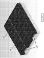
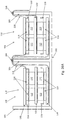
- FIGs 26A and 26B illustrate an embodiment of an electrochemical device 100 having four adjacent stacks 110 configured in a 2x2 pattern in a housing having four cavities 104 in the 2x2 pattern.
- the adjacent stacks 110 are electrically connected in series.
- adjacent stacks may be electrically connected in parallel.
- the electrical connection between adjacent stacks 110 may be made by joining the flexible, electrically conductive contacts 118 of the cell 111 of the adjacent stacks 110, such as by welding or brazing at locations 166 on top of the interior walls 105 of the housing 102.
- Fig. 26C is an exploded view of the housing 102 and lid 106 (with the lid removed from the housing) which enclose the stacks shown in Figs. 26A and 26B .
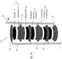
- the prismatic stack 110 also includes two electrical buses 134, 136.
- One electrical bus 134 electrically connected to the anode current collectors 132 in the prismatic stack 110 and one electrical bus connected 136 to the cathode current collectors 130 in the prismatic stack 1100.
- the electrical connection from the cathode and anode current collectors 130, 132 to the electrical buses 134, 136 is via the electrically conductive contacts 118. In this manner, the electrochemical cells 111 in the stack 110 can be electrically connected in parallel.
- All of the cavities 104 in the electrochemical device 100 may be similarly connected to each other as shown in Figure 26 .
- the flexible electrical connectors 118 may be configured such that stacks 110 of electrochemical cells 111 within the electrochemical device 100 are in series or in parallel or a combination thereof.
- the electrochemical device 100 includes at least one electrolyte port 162 in the lid 106. Electrolyte may be added to the electrochemical device 100 via the electrolyte ports 162.
- the electrolyte ports 162 may be covered with caps 163 to prevent spillage of electrolyte out of the electrolyte ports 162.
- the connector 140 may comprise electrical elements molded into the housing or installed in the housing that are configured to mate with the male or female portion of a power connector to electrically interconnect the electrochemical device unit 100 to another electrochemical device unit 100 or a power load as may be the case. Accordingly the stacks 110 of electrochemical cells 111 housed within the electrochemical device unit 100 can be electrically connected with other electrical elements using one or more terminals 133 described above by an electrical connector 140.
- the pass through connectors 140 of each of the electrochemical device units 100 in the assembly 200 are electrically connected to the pass through connectors of the adjacent electrochemical device units 100 in the assembly 200 to either charge or discharge the entire assembly 200 as a unit. These connections may be made in series or in parallel and alternatively can be made of, such as with wires 141 affixed to the terminals 133 or connectors 140 as shown in Figure 6 .
- assemblies 200 of electrochemical devices 100 are configured such that the stacks 110 of electrochemical cells 111 are assembled such that the cells 111 are under pressure.
- the stacks 110 bear most or all (e.g. at least 90%, such as 90-100%, e.g. 95-99%) of the compressive loading. That is, it is preferable that the housings 102 and the lids 106 bear little or no compressive loading (e.g. 0-10%, such as 1-5%).
- the housing 102 and the lid 106 are made of a flexible material (e.g. plastic, such as polypropylene) that bends or otherwise plastically deforms under a pressure/load applied by the pressure plates and the weight of the electrochemical device units stacked one above another.
- a flexible material e.g. plastic, such as polypropylene
- One or more elastic elements 208 may be provided between the pressure plates 202 and the electrochemical devices 100 in the assembly 200.
- Elastic elements 208 (see Figures 6 , 7A, 7B and 7C ) may be provided between the bottom pressure plate 202 and the stack of electrochemical devices 100, between the top pressure plate 202 and the stack of electrochemical devices 100 or between both pressure plates 202 and the stack of electrochemical devices 100.
- the elastic element 208 may be made of a springy material, such as silicone or rubber.
- a binding member 206 (such as the tie rod illustrated in Figure 7C , a cable or a spring), may be provided through the holes 160 in the lids 106 and holes 161 in the housings 102 of the electrochemical devices 100.
- the binding member 206 also passes through the pressure plates 202 ( Figures 8A-8C ).
- the binding member 206 may be secured to the pressure plates with tightening/securing members 207, such as a nut installed on a threaded end of the binding member 206 or the like tension the binding member 206.
- the tension in the binding member is used to force each pressure place into mating contact with the corresponding top and bottom electrochemical units 100 or the assembly or stack 200.
- tension in the binding member 206 is transferred to the pressure plates 202 which transfer the pressure force to the top and bottom electrochemical device units 100 in the assembly 200 which in turn transfer the pressure force to each of the remaining electrochemical device units 100 in the assembly 200.
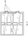
- the pressure plates 202, the housing bottom surfaces 420 shown in Figure 27 and lid cavities 107 are configured to align and interlock the units 100 and to transfer the pressure force applied to the pressure plates directly to the electrode stacks in each cavity such that tensioning the binding member 206 applies a compression force to each of the electrode stacks included in the assembly 200.
- Pressure may be applied to the assembly 200 by tightening the tightening/securing members 207, thereby causing the pressure plates to apply pressure or clamping force to the stack of electrochemical devices 100 in the assembly 200.
- the elastic elements 208 deform in response to the pressure force and tend to more uniformly distribute the pressure load over the bearings surfaces, specifically the lid cavities 107 and the housing bottom surfaces 420 and to more uniformly distribute the pressure force to each of the four load bearing surfaces of the lid cavities 107 and the bottom bearing surfaces 420.
- the binding member 206 has a fixed length and the pressure or clamping force is determined by the thickness of the elastic element(s) 208.
- the binding member 206 has a fixed length and the pressure or clamping force is applied by one or more compression springs disposed between the opposing pressure plates 202.
- a removable eye nut 210 may be affixed to the top of the binding member 206 to assist in lifting and otherwise handling the assembly 200.
- Figure 8A illustrates some dimensions that may be used to characterize the assembly 200.
- the distance 208x represents the thickness of the elastic element 208 (non-deflected).
- the distance 207x is measured from the bottom of a non-deflected elastic element 208 to the top of the bottom pressure plate 202.
- the distance 206x is the distance between the top and bottom pressure plates 202.
- the pressure force applied may be proportional to ratio of the thickness of non-deflected and the thickness of the elastic member element 208 after a pressure force is applied, i.e. the deflected thickness.
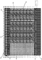
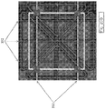
- FIG 10 illustrates a module 300 of assemblies 200 according to an embodiment.
- assemblies 200 are mounted on a base, such as a pallet 302.
- the module 300 may include twelve assemblies 200 in a 3 by 4 configuration.
- the module 300 may include any number of assemblies 200, such as 1 by 2, 1 by 3, 1 by 4, 2 by 3, 2 by 4, 3 by 5, etc.
- the module 300 preferably includes a module lid assembly 306, discussed in more detail below and a guard 308 that surrounds and protects the assemblies 200.
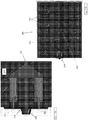
- FIG 11 illustrates an embodiment of a module 300 with the lid assembly removed.
- Adjacent assemblies 200 may be mechanically clamped to each other with one or more mechanical stack connectors 310, illustrated in more detail in Figure 12 .
- the stack connectors 310 are affixed to adjacent pressure plates 202.
- FIG. 13 illustrates a cross section through a module 300.
- the module 300 includes a module frame 303 located on a pallet 302. Frame 303 is configured to receive the assemblies 200. That is, the module frame 303 includes trenches to receive the feet 204 and the ribs 201 of the pressure plates 202 and thereby provide a more stable support for the assemblies 200.
- the module 300 also includes an actuator/push rod 312 and a module to module connector 314, for mechanically attaching modules together, as described in more detail below.
- the actuator/push rod 312 and module to module connector 314 allow adjacent modules 300 to be mechanically connected together to form an integrated electrochemical storage system comprising a plurality of electrochemical assemblies 200.
- Figure 16 illustrates top and bottom views of the lid assembly 306. As illustrated in Figure 16 , the lid assembly 306 includes recesses 317 configured to receive pressure plates 202 of individual assemblies 200 therein. Figure 16 also illustrates the placement of the actuator rod 312, module to module connector 314, stack connectors 310, space protectors 318 and contactors 320.
- Figures 17A, 17B and 18 provide details of a method of connecting modules with the mechanical module to module connector 314.
- the mechanical module to module connector 314 includes male plug locator 326 and two connector pins 322.
- the connector pins 322 are attached to the ends of connector blocks 324. In alternative embodiments, more or fewer connector pins 322 are used.
- the connector blocks 324 are operably connected to the actuator/push rod 312. In an embodiment, after all modules 300 are in place and aligned, a cam or protrusion (not shown) on the container door (not shown) contacts the last actuator/push rod 312 and all the connectors 314 are shuttled to the left (as illustrated), causing the connector pins 322 on one module to engage the female receptacles 323 on an adjacent module.
- Figure 18 illustrates the male locating plug 326 on one module approaching the female locating socket 328.
- Figures 19-21 illustrate details of an embodiment of a pallet assembly 302 for use with a module 300.
- the pallet assembly302 includes a pan 329 and a nest tray 330 located on the pan 329.
- the pan 329 and the nest tray 330 may be made of any suitable material, such as polyethylene.
- the nest tray includes recesses 317 configured to receive pressure plates 202 while the pan 329 includes fork tunnels 334 ( Figure 20A ) configured to receive the forks of a fork lift truck.
- the nest tray 330 also includes reinforcing structures 332 (e.g. steel bars, rods, plastic flanges etc.) to strengthen the nest tray 330 and to stabilize the modules 300.
- the reinforcing structures 332 may be provided in both lateral and longitudinal orientations to strengthen the nest tray 330.
- Figures 22A-22C illustrate a guard 308 for a module according to an embodiment.
- the guard 308 is a perforated enclosure made of steel, such as perforated 16 gauge steel.
- the guard 308 may be made of any suitable material.
- the guard 308 may be assembled in sections. In an embodiment, adjacent sections of the guard 308 are attached to each other with a guard interlock channel 309 ( Figure 22C ).
- the guard 308 may be affixed to the nest tray 330 by inserting a portion of the guard into a slot 336 in the nest tray 330 ( Figure 22B ).
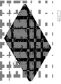
- FIGS 23A and 23B are electrical circuit diagrams that illustrate the internal 338 assembly 200 electrical connections in each module 300 and external 340 inter-module 300 electrical connections.
- the electrical connections may be located in a module lid assembly 306 and/or in a pallet assembly 302, respectively, according to an embodiment.
- the module lid assembly 306 may include both internal and external electrical connections 338, 340.
- the module 300 on the pallet assembly 302 only includes internal electrical connections 338 between the assemblies.
- the pallet assembly 302 includes internal and external electrical connections 338, 340 while the module lid assembly includes only internal electrical connections 338.
- both the module lid assembly 306 and the pallet assembly 302 include internal and external electrical connections 338, 340.
- each connector 342A may connect four assemblies 200 in series.
- the module 300 may include three connectors 342A for 12 assemblies.
- the module lid assembly 306 includes 3 mating connectors 342B, each of which may be electrically connected a respective assembly 200 connector 342A.
- the module 300 may include total of 12 assemblies 200.
- the modules 300 may include more or fewer assemblies 200 than 12 and may include more or fewer connectors 342.
- the connectors 342A, 342B with four electrical connections are for illustration only. Other connectors 342 with more of fewer electrical connections may be used as well.
- Connectors 342A, 342B may include, but are not limited to, Anderson Power Products Blind Mate series BMHSG-R and -P type connectors or other similar connectors.
- the pallet assembly 302 may contain charge control/ power electronics for charging each module 300 as a whole or for charging individual assemblies 200 or for charging individual electrochemical device units 100 or a combination thereof.
- the assemblies 200 in the module may be connected together either in series or in parallel, depending on the desired use of the module 300.
- the series/parallel connections may be located in either the module lid assembly 306 or the pallet assembly 302. If the series/parallel connections are provided in the module lid assembly 306, then the module 300 can be easily reconfigured by simply replacing a first module lid assembly 306 with one connection configuration with a second module lid assembly 306 having a different connection configuration.
- the assemblies 200 are connected in parallel via connectors 342A in the pallet assembly 302 while the modules 300 are connect to each other in series via the lid 106.
Landscapes
- Engineering & Computer Science (AREA)
- Power Engineering (AREA)
- Chemical & Material Sciences (AREA)
- Microelectronics & Electronic Packaging (AREA)
- Electrochemistry (AREA)
- Chemical Kinetics & Catalysis (AREA)
- Materials Engineering (AREA)
- General Chemical & Material Sciences (AREA)
- Electric Double-Layer Capacitors Or The Like (AREA)
- Connection Of Batteries Or Terminals (AREA)
- Secondary Cells (AREA)
- Battery Mounting, Suspending (AREA)
- Fuel Cell (AREA)
Applications Claiming Priority (3)
| Application Number | Priority Date | Filing Date | Title |
|---|---|---|---|
| US201261611416P | 2012-03-15 | 2012-03-15 | |
| US13/666,452 US8652672B2 (en) | 2012-03-15 | 2012-11-01 | Large format electrochemical energy storage device housing and module |
| PCT/US2013/031220 WO2013138561A1 (en) | 2012-03-15 | 2013-03-14 | Large format electrochemical energy storage device housing and module |
Publications (3)
| Publication Number | Publication Date |
|---|---|
| EP2826083A1 EP2826083A1 (en) | 2015-01-21 |
| EP2826083A4 EP2826083A4 (en) | 2015-11-11 |
| EP2826083B1 true EP2826083B1 (en) | 2017-07-12 |
Family
ID=47753406
Family Applications (1)
| Application Number | Title | Priority Date | Filing Date |
|---|---|---|---|
| EP13761001.0A Not-in-force EP2826083B1 (en) | 2012-03-15 | 2013-03-14 | Large format electrochemical energy storage device housing and module |
Country Status (9)
| Country | Link |
|---|---|
| US (3) | US8652672B2 (enExample) |
| EP (1) | EP2826083B1 (enExample) |
| JP (1) | JP6220849B2 (enExample) |
| KR (1) | KR20140138674A (enExample) |
| CN (1) | CN104170118A (enExample) |
| AU (1) | AU2013232062B2 (enExample) |
| CA (1) | CA2865623A1 (enExample) |
| EA (1) | EA201401009A1 (enExample) |
| WO (1) | WO2013138561A1 (enExample) |
Cited By (3)
| Publication number | Priority date | Publication date | Assignee | Title |
|---|---|---|---|---|
| DE102020128682A1 (de) | 2020-10-30 | 2022-05-05 | BlueSky Energy Entwicklungs- und ProduktionsGmbH | Batterie mit einem wässrigen alkalihaltigen Elektrolyten |
| DE102020129924A1 (de) | 2020-11-12 | 2022-05-12 | BlueSky Energy Entwicklungs- und ProduktionsGmbH | Verfahren zur Herstellung einer Elektrode für eine wässrige Alkali-Ionen Batterie oder eine wässrige Hybrid-Ionen Batterie |
| DE102021105018A1 (de) | 2021-03-02 | 2022-09-08 | Horst Wolf | Batterie mit einem wässrigem, alkalihaltigem Elektrolyten |
Families Citing this family (55)
| Publication number | Priority date | Publication date | Assignee | Title |
|---|---|---|---|---|
| US9098069B2 (en) | 2011-11-16 | 2015-08-04 | Google Technology Holdings LLC | Display device, corresponding systems, and methods for orienting output on a display |
| US8947382B2 (en) | 2012-02-28 | 2015-02-03 | Motorola Mobility Llc | Wearable display device, corresponding systems, and method for presenting output on the same |
| US8988349B2 (en) | 2012-02-28 | 2015-03-24 | Google Technology Holdings LLC | Methods and apparatuses for operating a display in an electronic device |
| US8652672B2 (en) | 2012-03-15 | 2014-02-18 | Aquion Energy, Inc. | Large format electrochemical energy storage device housing and module |
| EP2909875B1 (en) | 2012-10-16 | 2020-06-17 | Ambri Inc. | Electrochemical energy storage devices and housings |
| US9735450B2 (en) | 2012-10-18 | 2017-08-15 | Ambri Inc. | Electrochemical energy storage devices |
| US11721841B2 (en) | 2012-10-18 | 2023-08-08 | Ambri Inc. | Electrochemical energy storage devices |
| US10541451B2 (en) | 2012-10-18 | 2020-01-21 | Ambri Inc. | Electrochemical energy storage devices |
| US9520618B2 (en) | 2013-02-12 | 2016-12-13 | Ambri Inc. | Electrochemical energy storage devices |
| US11387497B2 (en) | 2012-10-18 | 2022-07-12 | Ambri Inc. | Electrochemical energy storage devices |
| US11211641B2 (en) | 2012-10-18 | 2021-12-28 | Ambri Inc. | Electrochemical energy storage devices |
| US9312522B2 (en) | 2012-10-18 | 2016-04-12 | Ambri Inc. | Electrochemical energy storage devices |
| US8945756B2 (en) | 2012-12-12 | 2015-02-03 | Aquion Energy Inc. | Composite anode structure for aqueous electrolyte energy storage and device containing same |
| US10270139B1 (en) | 2013-03-14 | 2019-04-23 | Ambri Inc. | Systems and methods for recycling electrochemical energy storage devices |
| US9502737B2 (en) | 2013-05-23 | 2016-11-22 | Ambri Inc. | Voltage-enhanced energy storage devices |
| US12347832B2 (en) | 2013-09-18 | 2025-07-01 | Ambri, LLC | Electrochemical energy storage devices |
| DK3058605T3 (da) | 2013-10-16 | 2024-03-04 | Ambri Inc | Tætninger til anordninger af reaktivt højtemperaturmateriale |
| WO2015058165A1 (en) | 2013-10-17 | 2015-04-23 | Ambri Inc. | Battery management systems for energy storage devices |
| US12142735B1 (en) | 2013-11-01 | 2024-11-12 | Ambri, Inc. | Thermal management of liquid metal batteries |
| US9616374B2 (en) * | 2013-12-14 | 2017-04-11 | Millenium Synthfuels Corporation | Multi-stage temperature based separation of gas impurities |
| US20160093848A1 (en) | 2014-09-30 | 2016-03-31 | Johnson Controls Technology Company | Modular approach for advanced battery modules having different electrical characteristics |
| KR102421778B1 (ko) * | 2014-11-14 | 2022-07-14 | 삼성에스디아이 주식회사 | 이차 전지 충전 장치 |
| US20180006280A1 (en) * | 2015-01-07 | 2018-01-04 | Eos Energy Storage, Llc | Containment system for battery modules |
| US10181800B1 (en) | 2015-03-02 | 2019-01-15 | Ambri Inc. | Power conversion systems for energy storage devices |
| WO2016141354A2 (en) | 2015-03-05 | 2016-09-09 | Ambri Inc. | Ceramic materials and seals for high temperature reactive material devices |
| US9893385B1 (en) | 2015-04-23 | 2018-02-13 | Ambri Inc. | Battery management systems for energy storage devices |
| US11603321B2 (en) | 2015-10-08 | 2023-03-14 | Everon24, Inc. | Rechargeable aluminum ion battery |
| US10559855B2 (en) | 2015-10-08 | 2020-02-11 | Everon24 Llc | Rechargeable aluminum ion battery |
| US9819220B2 (en) | 2015-10-08 | 2017-11-14 | Everon24 Llc | Rechargeable aluminum ion battery |
| US20170256760A1 (en) | 2016-03-03 | 2017-09-07 | Bosch Battery Systems GmbH | Battery Pack |
| DE102016104178A1 (de) | 2016-03-08 | 2017-09-14 | Dr. Ing. H.C. F. Porsche Aktiengesellschaft | Modul für eine Traktionsbatterie und entsprechende Traktionsbatterie für ein elektrisch betriebenes Fahrzeug |
| US10784545B2 (en) * | 2016-03-25 | 2020-09-22 | Xing Power Inc. | Submerged cell modular battery system |
| US10367175B2 (en) * | 2016-04-22 | 2019-07-30 | Bosch Bettery Systems LLC | Multicavity battery module |
| US11289700B2 (en) | 2016-06-28 | 2022-03-29 | The Research Foundation For The State University Of New York | KVOPO4 cathode for sodium ion batteries |
| CN106160082A (zh) * | 2016-07-13 | 2016-11-23 | 刘仲尧 | 一种微分锂电池组 |
| DE102016116729B4 (de) * | 2016-09-07 | 2020-12-31 | Kirchhoff Automotive Deutschland Gmbh | Batteriegehäuse für ein elektromotorisch angetriebenes Fahrzeug |
| US11929466B2 (en) | 2016-09-07 | 2024-03-12 | Ambri Inc. | Electrochemical energy storage devices |
| CN106329671B (zh) * | 2016-11-07 | 2019-03-19 | 天津市天楚科技有限公司 | 一种组合移动电源 |
| US20180170209A1 (en) * | 2016-12-16 | 2018-06-21 | Ford Global Technologies, Llc | Traction battery pack service panel |
| DE102016125697A1 (de) * | 2016-12-23 | 2018-06-28 | Benteler Automobiltechnik Gmbh | Batteriehalterung für ein Fahrzeug |
| CN110731027B (zh) | 2017-04-07 | 2024-06-18 | 安保瑞公司 | 具有固体金属阴极的熔盐电池 |
| CN110323377B (zh) * | 2018-03-30 | 2020-12-08 | 宁德时代新能源科技股份有限公司 | 防护压板以及电池模组 |
| WO2020131617A1 (en) | 2018-12-17 | 2020-06-25 | Ambri Inc. | High temperature energy storage systems and methods |
| CN111384328A (zh) | 2018-12-29 | 2020-07-07 | 比亚迪股份有限公司 | 电池托盘、动力电池包及车辆 |
| CN110190211B (zh) | 2018-12-29 | 2020-03-31 | 比亚迪股份有限公司 | 电池托盘、动力电池包及车辆 |
| US12230820B2 (en) | 2019-01-09 | 2025-02-18 | Byd Company Limited | Power battery pack and electric vehicle |
| KR102642864B1 (ko) | 2019-03-08 | 2024-03-05 | 알심 에너지, 인크. | 수계 알루미늄 이온 배터리, 하이브리드 배터리-커패시터, 상기 배터리 및 배터리-커패시터의 조성물, 및 연관된 제조 및 사용 방법 |
| US10978743B1 (en) | 2019-12-09 | 2021-04-13 | Natron Energy, Inc. | Optimization of electrochemical cell |
| US11518573B2 (en) * | 2020-02-14 | 2022-12-06 | Dell Products L.P. | Palletizing containers for charging electronic devices contained therein |
| US11462764B2 (en) | 2020-05-15 | 2022-10-04 | Ess Tech, Inc. | Double-stack redox flow battery |
| JP2023525857A (ja) | 2020-05-15 | 2023-06-19 | イーエスエス テック インコーポレーテッド | レドックスフロー電池 |
| BR102020015573A2 (pt) * | 2020-07-30 | 2022-02-08 | Enio Carlos Prudente | Conjunto blindado modular auto portante para proteção externa de baterias estacionarias. |
| EP4113556B1 (en) * | 2021-06-30 | 2023-09-20 | Mindcaps Smart Supercapacitors SL | Lithium/sodium electrochemical device for storing electrical energy in rectangular geometric cells |
| CN116918132A (zh) * | 2021-11-18 | 2023-10-20 | 宁德时代新能源科技股份有限公司 | 一种电池包及其用电装置 |
| EP4443574A4 (en) * | 2022-03-17 | 2025-10-15 | Standard Energy Inc | SECONDARY BATTERY |
Family Cites Families (117)
| Publication number | Priority date | Publication date | Assignee | Title |
|---|---|---|---|---|
| US3995008A (en) | 1975-02-20 | 1976-11-30 | Gould Inc. | Molded plastic battery container |
| US4100332A (en) | 1977-02-22 | 1978-07-11 | Energy Development Associates | Comb type bipolar electrode elements and battery stacks thereof |
| US4144381A (en) | 1977-09-20 | 1979-03-13 | Energy Development Associates | Electrochemical pH control |
| US4246253A (en) | 1978-09-29 | 1981-01-20 | Union Carbide Corporation | MnO2 derived from LiMn2 O4 |
| US4343868A (en) | 1980-12-31 | 1982-08-10 | Electric Power Research Institute, Inc. | Hydrogen ion-producing cell and technique for controlling the pH of battery electrolytes |
| US4623597A (en) | 1982-04-28 | 1986-11-18 | Energy Conversion Devices, Inc. | Rechargeable battery and electrode used therein |
| JPS5968182A (ja) * | 1982-10-12 | 1984-04-18 | Sanyo Electric Co Ltd | 鉛蓄電池の製造方法 |
| US4540639A (en) | 1982-12-01 | 1985-09-10 | Exxon Research & Engineering Company | Method and apparatus for maintaining the pH in zinc-bromine battery systems |
| US4849309A (en) | 1988-08-01 | 1989-07-18 | The United States Of America As Represented By The United States Department Of Energy | Overcharge tolerant high-temperature cells and batteries |
| JPH0748464B2 (ja) | 1989-09-12 | 1995-05-24 | いすゞ自動車株式会社 | 電気二重層コンデンサ |
| JPH067539B2 (ja) | 1989-09-14 | 1994-01-26 | いすゞ自動車株式会社 | 電気二重層コンデンサ |
| US5525442A (en) | 1990-09-14 | 1996-06-11 | Westinghouse Electric Corporation | Alkali metal battery |
| US5392873A (en) | 1992-01-22 | 1995-02-28 | Honda Giken Kogyo Kabushiki Kaisha | Structure for securing batteries used in an electric vehicle |
| ZA936168B (en) | 1992-08-28 | 1994-03-22 | Technology Finance Corp | Electrochemical cell |
| US5409787A (en) * | 1993-02-17 | 1995-04-25 | Electrosource, Inc. | Battery plate compression cage assembly |
| US5419977A (en) | 1994-03-09 | 1995-05-30 | Medtronic, Inc. | Electrochemical device having operatively combined capacitor |
| US5558961A (en) | 1994-06-13 | 1996-09-24 | Regents, University Of California | Secondary cell with orthorhombic alkali metal/manganese oxide phase active cathode material |
| US6682609B1 (en) | 1994-07-22 | 2004-01-27 | Kabushiki Kaisha Toshiba | Hydrogen absorbing alloy, method of surface modification of the alloy, negative electrode for battery and alkaline secondary battery |
| US5567544A (en) | 1995-05-26 | 1996-10-22 | Boundless Corp. | Battery |
| JP3070486B2 (ja) * | 1996-07-30 | 2000-07-31 | 日本電気株式会社 | 電気二重層コンデンサ |
| US5858573A (en) | 1996-08-23 | 1999-01-12 | Eic Laboratories, Inc. | Chemical overcharge protection of lithium and lithium-ion secondary batteries |
| JP2002511179A (ja) | 1996-10-11 | 2002-04-09 | マサチューセッツ・インスティテュート・オブ・テクノロジー | 電池のための固体電解質、インターカレーション化合物及び電極 |
| US5793603A (en) | 1996-11-19 | 1998-08-11 | Boundless Corp. | Ultracapacitor design having a honey comb structure |
| US6869547B2 (en) | 1996-12-09 | 2005-03-22 | Valence Technology, Inc. | Stabilized electrochemical cell active material |
| US5882812A (en) | 1997-01-14 | 1999-03-16 | Polyplus Battery Company, Inc. | Overcharge protection systems for rechargeable batteries |
| US6040089A (en) | 1997-02-28 | 2000-03-21 | Fmc Corporation | Multiple-doped oxide cathode material for secondary lithium and lithium-ion batteries |
| TW434187B (en) | 1997-05-07 | 2001-05-16 | Fuji Chem Ind Co Ltd | A process for preparing a spinel type of lithium manganese complex oxide |
| CA2240805C (en) | 1997-06-19 | 2005-07-26 | Tosoh Corporation | Spinel-type lithium-manganese oxide containing heteroelements, preparation process and use thereof |
| US6017654A (en) | 1997-08-04 | 2000-01-25 | Carnegie Mellon University | Cathode materials for lithium-ion secondary cells |
| US5882573A (en) | 1997-09-29 | 1999-03-16 | Illinois Tool Works Inc. | Adhesive dispensing nozzles for producing partial spray patterns and method therefor |
| JP3928231B2 (ja) | 1997-12-15 | 2007-06-13 | 株式会社日立製作所 | リチウム2次電池 |
| US5958624A (en) | 1997-12-18 | 1999-09-28 | Research Corporation Technologies, Inc. | Mesostructural metal oxide materials useful as an intercalation cathode or anode |
| US6159637A (en) | 1998-02-16 | 2000-12-12 | Mitsubishi Chemical Corporation | Lithium secondary cell and positive electrode material therefor |
| US6310762B1 (en) | 1998-03-03 | 2001-10-30 | Jeol Ltd. | Carbon material for electric double layer capacitor, method of producing same, electric double layer capacitor and method of fabricating same |
| US6787232B1 (en) | 1998-04-30 | 2004-09-07 | Massachusetts Institute Of Technology | Intercalation compounds and electrodes for batteries |
| US6465129B1 (en) | 1998-05-01 | 2002-10-15 | Regents Of The University Of Minnesota | Lithium batteries with new manganese oxide materials as lithium intercalation hosts |
| JP4185191B2 (ja) | 1998-07-31 | 2008-11-26 | 松下電器産業株式会社 | スピネル型マンガン酸リチウムの製造方法 |
| US6255015B1 (en) | 1998-08-23 | 2001-07-03 | Ovonic Battery Company, Inc. | Monoblock battery assembly |
| US6641951B1 (en) * | 1998-09-21 | 2003-11-04 | Douglas Battery Manufacturing Company | Battery cell tray assembly and sytem |
| US6162559A (en) * | 1998-09-21 | 2000-12-19 | Douglas Battery Manufacturing Company | Compressed battery system for motive power applications |
| US6267943B1 (en) | 1998-10-15 | 2001-07-31 | Fmc Corporation | Lithium manganese oxide spinel compound and method of preparing same |
| WO2000041256A1 (en) | 1999-01-08 | 2000-07-13 | Massachusetts Institute Of Technology | Electroactive material for secondary batteries and methods of preparation |
| US6322744B1 (en) | 1999-02-17 | 2001-11-27 | Valence Technology, Inc. | Lithium manganese oxide-based active material |
| US6252762B1 (en) | 1999-04-21 | 2001-06-26 | Telcordia Technologies, Inc. | Rechargeable hybrid battery/supercapacitor system |
| JP2000331682A (ja) | 1999-05-21 | 2000-11-30 | Mitsui Mining & Smelting Co Ltd | リチウム二次電池用正極材料及びこれを用いた電池 |
| JP4224186B2 (ja) | 1999-06-10 | 2009-02-12 | パナソニック株式会社 | 集合型二次電池 |
| US7199997B1 (en) | 2000-06-09 | 2007-04-03 | U.S. Nanocorp, Inc. | Asymmetric electrochemical supercapacitor and method of manufacture thereof |
| US7576971B2 (en) | 1999-06-11 | 2009-08-18 | U.S. Nanocorp, Inc. | Asymmetric electrochemical supercapacitor and method of manufacture thereof |
| KR100309773B1 (ko) | 1999-06-17 | 2001-11-01 | 김순택 | 리튬 이차 전지용 양극 활물질 및 그의 제조 방법 |
| US6248477B1 (en) | 1999-09-29 | 2001-06-19 | Kerr-Mcgee Chemical Llc | Cathode intercalation compositions, production methods and rechargeable lithium batteries containing the same |
| JP4572019B2 (ja) | 1999-10-08 | 2010-10-27 | パナソニック株式会社 | 組電池 |
| EP1142834A4 (en) | 1999-11-15 | 2009-06-17 | Mitsubishi Chem Corp | LITHIUM MANGANESE COMPOSITE OXIDE, POSITIVE ELECTRODE MATERIAL FOR LITHIUM SECONDARY ACCUMULATOR, POSITIVE ELECTRODE AND LITHIUM SECONDARY ACCUMULATOR, AND PROCESS FOR THE PREPARATION OF LITHIUM MANGANESE COMPOSITE OXIDE |
| US6673491B2 (en) | 2000-01-21 | 2004-01-06 | Showa Denko Kabushiki Kaisha | Cathode electroactive material, production method therefor, and nonaqueous secondary cell using the same |
| KR100398744B1 (ko) | 2000-02-16 | 2003-09-19 | 주식회사 엘지화학 | 전기화학적 성능이 향상된 리튬망간 스피넬 복합산화물의 제조방법 |
| US6777132B2 (en) | 2000-04-27 | 2004-08-17 | Valence Technology, Inc. | Alkali/transition metal halo—and hydroxy-phosphates and related electrode active materials |
| AU2001284816A1 (en) | 2000-08-10 | 2002-02-25 | Princeton University | Multifunctional battery and method of making the same |
| US6517972B1 (en) | 2000-09-29 | 2003-02-11 | Telcordia Technologies, Inc. | High energy density hybrid battery/supercapacitor system |
| US6455187B1 (en) | 2000-10-03 | 2002-09-24 | Premium Power Acquisition Corporation | Recombinator for the re-acidification of an electrolyte stream in a flowing electrolyte zinc-bromine battery |
| US6599657B1 (en) | 2000-11-08 | 2003-07-29 | Powerware Corporation | Battery pack housing and battery pack and power supply device incorporating the same |
| EP1233001B1 (en) | 2001-02-16 | 2010-09-15 | Tosoh Corporation | Lithium-manganese complex oxide, production method thereof and use thereof |
| EP1239495B1 (en) | 2001-03-09 | 2006-08-09 | Asahi Glass Company Ltd. | Secondary power source |
| WO2002097907A2 (en) | 2001-04-06 | 2002-12-05 | Valence Technology, Inc. | Sodium ion batteries |
| US6878490B2 (en) | 2001-08-20 | 2005-04-12 | Fmc Corporation | Positive electrode active materials for secondary batteries and methods of preparing same |
| JP3875053B2 (ja) | 2001-09-10 | 2007-01-31 | 日本電信電話株式会社 | 電極材料、その製造方法及びそれを用いた電池 |
| US6783893B2 (en) | 2001-11-19 | 2004-08-31 | The Gillette Company | Alkaline battery |
| US6757154B2 (en) | 2001-12-13 | 2004-06-29 | Advanced Energy Technology Inc. | Double-layer capacitor components and method for preparing them |
| US6815122B2 (en) | 2002-03-06 | 2004-11-09 | Valence Technology, Inc. | Alkali transition metal phosphates and related electrode active materials |
| US20030186128A1 (en) | 2002-03-29 | 2003-10-02 | Deepika Singh | Lithium-based rechargeable batteries |
| US7422823B2 (en) | 2002-04-03 | 2008-09-09 | Valence Technology, Inc. | Alkali-iron-cobalt phosphates and related electrode active materials |
| US20030190527A1 (en) | 2002-04-03 | 2003-10-09 | James Pugh | Batteries comprising alkali-transition metal phosphates and preferred electrolytes |
| US20090220838A9 (en) | 2002-04-04 | 2009-09-03 | Jeremy Barker | Secondary electrochemical cell |
| JP4218267B2 (ja) * | 2002-07-08 | 2009-02-04 | トヨタ自動車株式会社 | 集合電池 |
| JP2004055346A (ja) * | 2002-07-19 | 2004-02-19 | Nissan Motor Co Ltd | 組電池、複合組電池およびそれを搭載した車両 |
| EP1547973A4 (en) | 2002-09-05 | 2008-07-30 | Nat Inst Of Advanced Ind Scien | FINE CARBON POWDER WITH METAL OXIDE, METAL-NITRIDE OR METAL CARBIDE COATING, MANUFACTURING METHOD DAF R AND SUPERCONDENSATOR AND SECONDARY BATTERY USING THE FINE CARBON POWDER |
| JP2004265749A (ja) | 2003-03-03 | 2004-09-24 | Ngk Insulators Ltd | リチウム二次電池 |
| FR2852148B1 (fr) | 2003-03-07 | 2014-04-11 | Batscap Sa | Materiau pour electrode composite, procede pour sa preparation |
| WO2004088777A1 (ja) | 2003-03-31 | 2004-10-14 | Nec Corporation | 二次電池用正極活物質、二次電池、および二次電池用正極活物質の製造方法 |
| US7041239B2 (en) | 2003-04-03 | 2006-05-09 | Valence Technology, Inc. | Electrodes comprising mixed active particles |
| CN100438144C (zh) | 2003-05-26 | 2008-11-26 | 日本电气株式会社 | 二次电池用正极活性材料,二次电池用正极,二次电池及制备二次电池用正极活性材料的方法 |
| US7901810B2 (en) | 2003-06-03 | 2011-03-08 | Valence Technology, Inc. | Battery active materials and methods for synthesis |
| US20050031921A1 (en) | 2003-08-07 | 2005-02-10 | Ovshinsky Stanford R. | Hybrid fuel cell |
| US7920371B2 (en) | 2003-09-12 | 2011-04-05 | Maxwell Technologies, Inc. | Electrical energy storage devices with separator between electrodes and methods for fabricating the devices |
| JP4211561B2 (ja) * | 2003-10-10 | 2009-01-21 | 日産自動車株式会社 | 組電池 |
| US7008726B2 (en) | 2004-01-22 | 2006-03-07 | Valence Technology, Inc. | Secondary battery electrode active materials and methods for making the same |
| US7785740B2 (en) | 2004-04-09 | 2010-08-31 | Air Products And Chemicals, Inc. | Overcharge protection for electrochemical cells |
| WO2005114811A2 (en) | 2004-05-17 | 2005-12-01 | Railpower Technologies Corp. | Design of a large battery pack for a hybrid locomotive |
| US7547487B1 (en) | 2004-05-18 | 2009-06-16 | Ovonic Battery Company, Inc. | Multi-cell battery assembly |
| KR100982595B1 (ko) | 2005-02-07 | 2010-09-15 | 산요덴키가부시키가이샤 | 정극 및 비수 전해질 이차 전지 |
| CN1328818C (zh) | 2005-04-21 | 2007-07-25 | 复旦大学 | 混合型水系锂离子电池 |
| US8129052B2 (en) | 2005-09-02 | 2012-03-06 | Polyplus Battery Company | Polymer adhesive seals for protected anode architectures |
| EP1768141B1 (en) | 2005-09-26 | 2009-09-02 | Nisshinbo Industries, Inc. | Polarizable electrode for electric double layer capacitor |
| JP5028812B2 (ja) * | 2006-02-09 | 2012-09-19 | 日産自動車株式会社 | 電池モジュール |
| JP2007266064A (ja) | 2006-03-27 | 2007-10-11 | Honda Motor Co Ltd | 電気二重層キャパシタ |
| US7972726B2 (en) | 2006-07-10 | 2011-07-05 | The Gillette Company | Primary alkaline battery containing bismuth metal oxide |
| CN101507021A (zh) | 2006-08-31 | 2009-08-12 | 萤火虫能源公司 | 碳泡沫的外部稳定 |
| EP1901388A1 (en) | 2006-09-14 | 2008-03-19 | High Power Lithium S.A. | Overcharge and overdischarge protection in lithium-ion batteries |
| DE102006061270B4 (de) * | 2006-12-22 | 2021-10-14 | Robert Bosch Gmbh | Batteriepack und Batteriemodul |
| US7713505B2 (en) | 2007-06-05 | 2010-05-11 | Gm Global Technology Operations, Inc. | XLi3N2 compounds and their hydrides as hydrogen storage materials |
| CN101154745A (zh) | 2007-09-20 | 2008-04-02 | 复旦大学 | 一种水系可充锂或钠离子电池 |
| US8665880B2 (en) | 2007-09-21 | 2014-03-04 | Qualcomm Incorporated | Techniques for distributing content to multiple devices in a communication network |
| CA2720600C (en) | 2008-04-07 | 2017-09-12 | Jay Whitacre | Sodium ion based aqueous electrolyte electrochemical secondary energy storage device |
| JP2010003803A (ja) * | 2008-06-19 | 2010-01-07 | Taiyo Yuden Co Ltd | 電気化学デバイス及びその製造方法 |
| US7855011B2 (en) | 2008-08-28 | 2010-12-21 | International Battery, Inc. | Monoblock lithium ion battery |
| CN105047956A (zh) * | 2009-01-27 | 2015-11-11 | G4协同学公司 | 用于储能器件的可变容积的容器 |
| EP2475029B1 (en) * | 2009-09-01 | 2019-09-11 | Nissan Motor Co., Ltd | Battery with convex portions formed on collector plates |
| US8900746B2 (en) | 2009-10-13 | 2014-12-02 | Kabushiki Kaisha Toyota Chuo Kenkyusho | Aqueous secondary battery |
| US20120286739A1 (en) * | 2009-12-11 | 2012-11-15 | A123 Systems, Inc. | System and Method for Estimating a State of a Battery Pack |
| US9083029B2 (en) * | 2009-12-23 | 2015-07-14 | Samsung Sdi Co., Ltd. | Battery pack |
| JP5368589B2 (ja) * | 2010-01-28 | 2013-12-18 | 三菱電機株式会社 | 電力貯蔵デバイスセルとその製造方法および蓄電デバイス |
| KR101101455B1 (ko) * | 2010-05-20 | 2012-01-03 | 삼성전기주식회사 | 전기 이중층 커패시터 패키지 및 그 제조방법 |
| KR101108855B1 (ko) | 2010-06-23 | 2012-01-31 | 삼성전기주식회사 | 전기 화학 커패시터 |
| US20120244397A1 (en) * | 2010-07-12 | 2012-09-27 | Coda Automotive, Inc. | Battery assembly |
| US8298701B2 (en) | 2011-03-09 | 2012-10-30 | Aquion Energy Inc. | Aqueous electrolyte energy storage device |
| CN105761941B (zh) * | 2011-03-09 | 2018-07-13 | 亚奎尼能源公司 | 不含金属的含水电解质能量存储装置 |
| US8137830B2 (en) | 2011-07-19 | 2012-03-20 | Aquion Energy, Inc. | High voltage battery composed of anode limited electrochemical cells |
| JP5965615B2 (ja) * | 2011-11-14 | 2016-08-10 | Udトラックス株式会社 | 蓄電装置 |
| US8652672B2 (en) | 2012-03-15 | 2014-02-18 | Aquion Energy, Inc. | Large format electrochemical energy storage device housing and module |
-
2012
- 2012-11-01 US US13/666,452 patent/US8652672B2/en not_active Expired - Fee Related
-
2013
- 2013-03-14 AU AU2013232062A patent/AU2013232062B2/en not_active Ceased
- 2013-03-14 KR KR1020147024343A patent/KR20140138674A/ko not_active Ceased
- 2013-03-14 CA CA2865623A patent/CA2865623A1/en not_active Abandoned
- 2013-03-14 WO PCT/US2013/031220 patent/WO2013138561A1/en not_active Ceased
- 2013-03-14 CN CN201380014349.4A patent/CN104170118A/zh active Pending
- 2013-03-14 EP EP13761001.0A patent/EP2826083B1/en not_active Not-in-force
- 2013-03-14 JP JP2015500600A patent/JP6220849B2/ja not_active Expired - Fee Related
- 2013-03-14 EA EA201401009A patent/EA201401009A1/ru unknown
-
2014
- 2014-02-11 US US14/178,062 patent/US9331320B2/en not_active Expired - Fee Related
-
2016
- 2016-04-06 US US15/091,764 patent/US20160218334A1/en not_active Abandoned
Non-Patent Citations (1)
| Title |
|---|
| None * |
Cited By (6)
| Publication number | Priority date | Publication date | Assignee | Title |
|---|---|---|---|---|
| DE102020128682A1 (de) | 2020-10-30 | 2022-05-05 | BlueSky Energy Entwicklungs- und ProduktionsGmbH | Batterie mit einem wässrigen alkalihaltigen Elektrolyten |
| WO2022090215A1 (de) | 2020-10-30 | 2022-05-05 | BlueSky Energy Entwicklungs- und ProduktionsGmbH | Batterie mit einem wässrigen alkalihaltigen elektrolyten |
| DE102020129924A1 (de) | 2020-11-12 | 2022-05-12 | BlueSky Energy Entwicklungs- und ProduktionsGmbH | Verfahren zur Herstellung einer Elektrode für eine wässrige Alkali-Ionen Batterie oder eine wässrige Hybrid-Ionen Batterie |
| WO2022101002A2 (de) | 2020-11-12 | 2022-05-19 | BlueSky Energy Entwicklungs- und ProduktionsGmbH | Verfahren zur herstellung einer elektrode für eine wässrige alkali-ionen batterie oder eine wässrige hybrid-ionen batterie |
| DE102021105018A1 (de) | 2021-03-02 | 2022-09-08 | Horst Wolf | Batterie mit einem wässrigem, alkalihaltigem Elektrolyten |
| WO2022184761A1 (de) | 2021-03-02 | 2022-09-09 | Horst Wolf | Batterie mit einem wässrigem, alkalihaltigem elektrolyten |
Also Published As
| Publication number | Publication date |
|---|---|
| CA2865623A1 (en) | 2013-09-19 |
| US9331320B2 (en) | 2016-05-03 |
| EP2826083A4 (en) | 2015-11-11 |
| US20140162090A1 (en) | 2014-06-12 |
| KR20140138674A (ko) | 2014-12-04 |
| WO2013138561A1 (en) | 2013-09-19 |
| US8652672B2 (en) | 2014-02-18 |
| AU2013232062B2 (en) | 2016-09-08 |
| US20160218334A1 (en) | 2016-07-28 |
| JP2015516645A (ja) | 2015-06-11 |
| EP2826083A1 (en) | 2015-01-21 |
| EA201401009A1 (ru) | 2015-01-30 |
| AU2013232062A1 (en) | 2014-09-18 |
| JP6220849B2 (ja) | 2017-10-25 |
| CN104170118A (zh) | 2014-11-26 |
| US20130059185A1 (en) | 2013-03-07 |
Similar Documents
| Publication | Publication Date | Title |
|---|---|---|
| EP2826083B1 (en) | Large format electrochemical energy storage device housing and module | |
| EP2325923B1 (en) | Battery pack with improved stability | |
| US8465866B2 (en) | Battery module including a pressure control unit | |
| KR101359710B1 (ko) | 전지 장착용 케이스 및 이를 구비한 전지 어셈블리 | |
| KR101152635B1 (ko) | 전지모듈용 전압 검출 어셈블리 및 이를 포함하는 전지모듈 | |
| EP2562842B1 (en) | Battery module | |
| US20110151311A1 (en) | Battery pack | |
| US9543550B2 (en) | Battery cell module, battery, and motor vehicle | |
| US20120196174A1 (en) | Electrical energy storage cell and cell block, electrical energy storage device and the vehicle comprising the same | |
| KR102444124B1 (ko) | 배터리 모듈 및 이를 포함하는 배터리 팩 | |
| CA2661100A1 (en) | Electrochemical cell for hybrid electric vehicle applications | |
| EP3154108B1 (en) | Battery module and battery pack including same | |
| KR20070116295A (ko) | 두 개 이상의 유닛 셀들을 포함하고 있는 고용량 전지셀 | |
| KR20190009340A (ko) | 커버 어셈블리를 포함한 배터리 모듈 | |
| KR20120074415A (ko) | 신규한 구조의 단위모듈 및 이를 포함하는 전지모듈 | |
| KR102760922B1 (ko) | 배터리, 전기기기 및 배터리의 제조 방법 | |
| KR20130012469A (ko) | 에너지 저장 모듈 | |
| US20250323373A1 (en) | Battery system with improved end plate | |
| KR20250139014A (ko) | 배터리 셀 및 이를 포함하는 배터리 모듈 |
Legal Events
| Date | Code | Title | Description |
|---|---|---|---|
| PUAI | Public reference made under article 153(3) epc to a published international application that has entered the european phase |
Free format text: ORIGINAL CODE: 0009012 |
|
| 17P | Request for examination filed |
Effective date: 20140925 |
|
| AK | Designated contracting states |
Kind code of ref document: A1 Designated state(s): AL AT BE BG CH CY CZ DE DK EE ES FI FR GB GR HR HU IE IS IT LI LT LU LV MC MK MT NL NO PL PT RO RS SE SI SK SM TR |
|
| AX | Request for extension of the european patent |
Extension state: BA ME |
|
| DAX | Request for extension of the european patent (deleted) | ||
| RIC1 | Information provided on ipc code assigned before grant |
Ipc: H01M 10/02 20060101ALI20150819BHEP Ipc: H01M 12/00 20060101ALN20150819BHEP Ipc: H01M 2/10 20060101AFI20150819BHEP |
|
| RA4 | Supplementary search report drawn up and despatched (corrected) |
Effective date: 20151013 |
|
| RIC1 | Information provided on ipc code assigned before grant |
Ipc: H01M 12/00 20060101ALN20151007BHEP Ipc: H01M 10/02 20060101ALI20151007BHEP Ipc: H01M 2/10 20060101AFI20151007BHEP |
|
| R17P | Request for examination filed (corrected) |
Effective date: 20140925 |
|
| GRAP | Despatch of communication of intention to grant a patent |
Free format text: ORIGINAL CODE: EPIDOSNIGR1 |
|
| RIC1 | Information provided on ipc code assigned before grant |
Ipc: H01M 12/00 20060101ALN20170116BHEP Ipc: H01M 2/10 20060101AFI20170116BHEP Ipc: H01M 10/02 20060101ALI20170116BHEP |
|
| INTG | Intention to grant announced |
Effective date: 20170130 |
|
| GRAS | Grant fee paid |
Free format text: ORIGINAL CODE: EPIDOSNIGR3 |
|
| GRAA | (expected) grant |
Free format text: ORIGINAL CODE: 0009210 |
|
| AK | Designated contracting states |
Kind code of ref document: B1 Designated state(s): AL AT BE BG CH CY CZ DE DK EE ES FI FR GB GR HR HU IE IS IT LI LT LU LV MC MK MT NL NO PL PT RO RS SE SI SK SM TR |
|
| REG | Reference to a national code |
Ref country code: GB Ref legal event code: FG4D |
|
| REG | Reference to a national code |
Ref country code: CH Ref legal event code: EP |
|
| REG | Reference to a national code |
Ref country code: AT Ref legal event code: REF Ref document number: 909121 Country of ref document: AT Kind code of ref document: T Effective date: 20170715 |
|
| REG | Reference to a national code |
Ref country code: IE Ref legal event code: FG4D |
|
| REG | Reference to a national code |
Ref country code: DE Ref legal event code: R096 Ref document number: 602013023458 Country of ref document: DE |
|
| REG | Reference to a national code |
Ref country code: NL Ref legal event code: MP Effective date: 20170712 |
|
| REG | Reference to a national code |
Ref country code: LT Ref legal event code: MG4D |
|
| REG | Reference to a national code |
Ref country code: AT Ref legal event code: MK05 Ref document number: 909121 Country of ref document: AT Kind code of ref document: T Effective date: 20170712 |
|
| PG25 | Lapsed in a contracting state [announced via postgrant information from national office to epo] |
Ref country code: NO Free format text: LAPSE BECAUSE OF FAILURE TO SUBMIT A TRANSLATION OF THE DESCRIPTION OR TO PAY THE FEE WITHIN THE PRESCRIBED TIME-LIMIT Effective date: 20171012 Ref country code: FI Free format text: LAPSE BECAUSE OF FAILURE TO SUBMIT A TRANSLATION OF THE DESCRIPTION OR TO PAY THE FEE WITHIN THE PRESCRIBED TIME-LIMIT Effective date: 20170712 Ref country code: NL Free format text: LAPSE BECAUSE OF FAILURE TO SUBMIT A TRANSLATION OF THE DESCRIPTION OR TO PAY THE FEE WITHIN THE PRESCRIBED TIME-LIMIT Effective date: 20170712 Ref country code: LT Free format text: LAPSE BECAUSE OF FAILURE TO SUBMIT A TRANSLATION OF THE DESCRIPTION OR TO PAY THE FEE WITHIN THE PRESCRIBED TIME-LIMIT Effective date: 20170712 Ref country code: SE Free format text: LAPSE BECAUSE OF FAILURE TO SUBMIT A TRANSLATION OF THE DESCRIPTION OR TO PAY THE FEE WITHIN THE PRESCRIBED TIME-LIMIT Effective date: 20170712 Ref country code: AT Free format text: LAPSE BECAUSE OF FAILURE TO SUBMIT A TRANSLATION OF THE DESCRIPTION OR TO PAY THE FEE WITHIN THE PRESCRIBED TIME-LIMIT Effective date: 20170712 Ref country code: HR Free format text: LAPSE BECAUSE OF FAILURE TO SUBMIT A TRANSLATION OF THE DESCRIPTION OR TO PAY THE FEE WITHIN THE PRESCRIBED TIME-LIMIT Effective date: 20170712 |
|
| PG25 | Lapsed in a contracting state [announced via postgrant information from national office to epo] |
Ref country code: RS Free format text: LAPSE BECAUSE OF FAILURE TO SUBMIT A TRANSLATION OF THE DESCRIPTION OR TO PAY THE FEE WITHIN THE PRESCRIBED TIME-LIMIT Effective date: 20170712 Ref country code: IS Free format text: LAPSE BECAUSE OF FAILURE TO SUBMIT A TRANSLATION OF THE DESCRIPTION OR TO PAY THE FEE WITHIN THE PRESCRIBED TIME-LIMIT Effective date: 20171112 Ref country code: GR Free format text: LAPSE BECAUSE OF FAILURE TO SUBMIT A TRANSLATION OF THE DESCRIPTION OR TO PAY THE FEE WITHIN THE PRESCRIBED TIME-LIMIT Effective date: 20171013 Ref country code: ES Free format text: LAPSE BECAUSE OF FAILURE TO SUBMIT A TRANSLATION OF THE DESCRIPTION OR TO PAY THE FEE WITHIN THE PRESCRIBED TIME-LIMIT Effective date: 20170712 Ref country code: PL Free format text: LAPSE BECAUSE OF FAILURE TO SUBMIT A TRANSLATION OF THE DESCRIPTION OR TO PAY THE FEE WITHIN THE PRESCRIBED TIME-LIMIT Effective date: 20170712 Ref country code: LV Free format text: LAPSE BECAUSE OF FAILURE TO SUBMIT A TRANSLATION OF THE DESCRIPTION OR TO PAY THE FEE WITHIN THE PRESCRIBED TIME-LIMIT Effective date: 20170712 Ref country code: BG Free format text: LAPSE BECAUSE OF FAILURE TO SUBMIT A TRANSLATION OF THE DESCRIPTION OR TO PAY THE FEE WITHIN THE PRESCRIBED TIME-LIMIT Effective date: 20171012 |
|
| REG | Reference to a national code |
Ref country code: FR Ref legal event code: PLFP Year of fee payment: 6 |
|
| REG | Reference to a national code |
Ref country code: DE Ref legal event code: R097 Ref document number: 602013023458 Country of ref document: DE |
|
| PG25 | Lapsed in a contracting state [announced via postgrant information from national office to epo] |
Ref country code: CZ Free format text: LAPSE BECAUSE OF FAILURE TO SUBMIT A TRANSLATION OF THE DESCRIPTION OR TO PAY THE FEE WITHIN THE PRESCRIBED TIME-LIMIT Effective date: 20170712 Ref country code: DK Free format text: LAPSE BECAUSE OF FAILURE TO SUBMIT A TRANSLATION OF THE DESCRIPTION OR TO PAY THE FEE WITHIN THE PRESCRIBED TIME-LIMIT Effective date: 20170712 Ref country code: RO Free format text: LAPSE BECAUSE OF FAILURE TO SUBMIT A TRANSLATION OF THE DESCRIPTION OR TO PAY THE FEE WITHIN THE PRESCRIBED TIME-LIMIT Effective date: 20170712 |
|
| PGFP | Annual fee paid to national office [announced via postgrant information from national office to epo] |
Ref country code: GB Payment date: 20180327 Year of fee payment: 6 |
|
| PLBE | No opposition filed within time limit |
Free format text: ORIGINAL CODE: 0009261 |
|
| STAA | Information on the status of an ep patent application or granted ep patent |
Free format text: STATUS: NO OPPOSITION FILED WITHIN TIME LIMIT |
|
| PG25 | Lapsed in a contracting state [announced via postgrant information from national office to epo] |
Ref country code: IT Free format text: LAPSE BECAUSE OF FAILURE TO SUBMIT A TRANSLATION OF THE DESCRIPTION OR TO PAY THE FEE WITHIN THE PRESCRIBED TIME-LIMIT Effective date: 20170712 Ref country code: SK Free format text: LAPSE BECAUSE OF FAILURE TO SUBMIT A TRANSLATION OF THE DESCRIPTION OR TO PAY THE FEE WITHIN THE PRESCRIBED TIME-LIMIT Effective date: 20170712 Ref country code: SM Free format text: LAPSE BECAUSE OF FAILURE TO SUBMIT A TRANSLATION OF THE DESCRIPTION OR TO PAY THE FEE WITHIN THE PRESCRIBED TIME-LIMIT Effective date: 20170712 Ref country code: EE Free format text: LAPSE BECAUSE OF FAILURE TO SUBMIT A TRANSLATION OF THE DESCRIPTION OR TO PAY THE FEE WITHIN THE PRESCRIBED TIME-LIMIT Effective date: 20170712 |
|
| PGFP | Annual fee paid to national office [announced via postgrant information from national office to epo] |
Ref country code: FR Payment date: 20180326 Year of fee payment: 6 |
|
| 26N | No opposition filed |
Effective date: 20180413 |
|
| PGFP | Annual fee paid to national office [announced via postgrant information from national office to epo] |
Ref country code: DE Payment date: 20180328 Year of fee payment: 6 |
|
| PG25 | Lapsed in a contracting state [announced via postgrant information from national office to epo] |
Ref country code: SI Free format text: LAPSE BECAUSE OF FAILURE TO SUBMIT A TRANSLATION OF THE DESCRIPTION OR TO PAY THE FEE WITHIN THE PRESCRIBED TIME-LIMIT Effective date: 20170712 |
|
| REG | Reference to a national code |
Ref country code: CH Ref legal event code: PL |
|
| PG25 | Lapsed in a contracting state [announced via postgrant information from national office to epo] |
Ref country code: MC Free format text: LAPSE BECAUSE OF FAILURE TO SUBMIT A TRANSLATION OF THE DESCRIPTION OR TO PAY THE FEE WITHIN THE PRESCRIBED TIME-LIMIT Effective date: 20170712 |
|
| REG | Reference to a national code |
Ref country code: BE Ref legal event code: MM Effective date: 20180331 |
|
| REG | Reference to a national code |
Ref country code: IE Ref legal event code: MM4A |
|
| PG25 | Lapsed in a contracting state [announced via postgrant information from national office to epo] |
Ref country code: LU Free format text: LAPSE BECAUSE OF NON-PAYMENT OF DUE FEES Effective date: 20180314 |
|
| PG25 | Lapsed in a contracting state [announced via postgrant information from national office to epo] |
Ref country code: IE Free format text: LAPSE BECAUSE OF NON-PAYMENT OF DUE FEES Effective date: 20180314 |
|
| PG25 | Lapsed in a contracting state [announced via postgrant information from national office to epo] |
Ref country code: CH Free format text: LAPSE BECAUSE OF NON-PAYMENT OF DUE FEES Effective date: 20180331 Ref country code: LI Free format text: LAPSE BECAUSE OF NON-PAYMENT OF DUE FEES Effective date: 20180331 Ref country code: BE Free format text: LAPSE BECAUSE OF NON-PAYMENT OF DUE FEES Effective date: 20180331 |
|
| REG | Reference to a national code |
Ref country code: DE Ref legal event code: R119 Ref document number: 602013023458 Country of ref document: DE |
|
| GBPC | Gb: european patent ceased through non-payment of renewal fee |
Effective date: 20190314 |
|
| PG25 | Lapsed in a contracting state [announced via postgrant information from national office to epo] |
Ref country code: DE Free format text: LAPSE BECAUSE OF NON-PAYMENT OF DUE FEES Effective date: 20191001 Ref country code: MT Free format text: LAPSE BECAUSE OF NON-PAYMENT OF DUE FEES Effective date: 20180314 Ref country code: GB Free format text: LAPSE BECAUSE OF NON-PAYMENT OF DUE FEES Effective date: 20190314 |
|
| PG25 | Lapsed in a contracting state [announced via postgrant information from national office to epo] |
Ref country code: FR Free format text: LAPSE BECAUSE OF NON-PAYMENT OF DUE FEES Effective date: 20190331 |
|
| PG25 | Lapsed in a contracting state [announced via postgrant information from national office to epo] |
Ref country code: TR Free format text: LAPSE BECAUSE OF FAILURE TO SUBMIT A TRANSLATION OF THE DESCRIPTION OR TO PAY THE FEE WITHIN THE PRESCRIBED TIME-LIMIT Effective date: 20170712 |
|
| PG25 | Lapsed in a contracting state [announced via postgrant information from national office to epo] |
Ref country code: HU Free format text: LAPSE BECAUSE OF FAILURE TO SUBMIT A TRANSLATION OF THE DESCRIPTION OR TO PAY THE FEE WITHIN THE PRESCRIBED TIME-LIMIT; INVALID AB INITIO Effective date: 20130314 Ref country code: PT Free format text: LAPSE BECAUSE OF FAILURE TO SUBMIT A TRANSLATION OF THE DESCRIPTION OR TO PAY THE FEE WITHIN THE PRESCRIBED TIME-LIMIT Effective date: 20170712 |
|
| PG25 | Lapsed in a contracting state [announced via postgrant information from national office to epo] |
Ref country code: CY Free format text: LAPSE BECAUSE OF FAILURE TO SUBMIT A TRANSLATION OF THE DESCRIPTION OR TO PAY THE FEE WITHIN THE PRESCRIBED TIME-LIMIT Effective date: 20170712 Ref country code: MK Free format text: LAPSE BECAUSE OF NON-PAYMENT OF DUE FEES Effective date: 20170712 |
|
| PG25 | Lapsed in a contracting state [announced via postgrant information from national office to epo] |
Ref country code: AL Free format text: LAPSE BECAUSE OF FAILURE TO SUBMIT A TRANSLATION OF THE DESCRIPTION OR TO PAY THE FEE WITHIN THE PRESCRIBED TIME-LIMIT Effective date: 20170712 |