EP2825418B1 - Heckbereichsmodul und heckbreichssteuergerät - Google Patents
Heckbereichsmodul und heckbreichssteuergerät Download PDFInfo
- Publication number
- EP2825418B1 EP2825418B1 EP13716515.5A EP13716515A EP2825418B1 EP 2825418 B1 EP2825418 B1 EP 2825418B1 EP 13716515 A EP13716515 A EP 13716515A EP 2825418 B1 EP2825418 B1 EP 2825418B1
- Authority
- EP
- European Patent Office
- Prior art keywords
- subcircuit
- plg
- pole
- heated back
- wiper
- Prior art date
- Legal status (The legal status is an assumption and is not a legal conclusion. Google has not performed a legal analysis and makes no representation as to the accuracy of the status listed.)
- Active
Links
Images







Classifications
-
- B—PERFORMING OPERATIONS; TRANSPORTING
- B60—VEHICLES IN GENERAL
- B60W—CONJOINT CONTROL OF VEHICLE SUB-UNITS OF DIFFERENT TYPE OR DIFFERENT FUNCTION; CONTROL SYSTEMS SPECIALLY ADAPTED FOR HYBRID VEHICLES; ROAD VEHICLE DRIVE CONTROL SYSTEMS FOR PURPOSES NOT RELATED TO THE CONTROL OF A PARTICULAR SUB-UNIT
- B60W50/00—Details of control systems for road vehicle drive control not related to the control of a particular sub-unit, e.g. process diagnostic or vehicle driver interfaces
- B60W50/0098—Details of control systems ensuring comfort, safety or stability not otherwise provided for
-
- B—PERFORMING OPERATIONS; TRANSPORTING
- B60—VEHICLES IN GENERAL
- B60R—VEHICLES, VEHICLE FITTINGS, OR VEHICLE PARTS, NOT OTHERWISE PROVIDED FOR
- B60R16/00—Electric or fluid circuits specially adapted for vehicles and not otherwise provided for; Arrangement of elements of electric or fluid circuits specially adapted for vehicles and not otherwise provided for
- B60R16/02—Electric or fluid circuits specially adapted for vehicles and not otherwise provided for; Arrangement of elements of electric or fluid circuits specially adapted for vehicles and not otherwise provided for electric constitutive elements
- B60R16/03—Electric or fluid circuits specially adapted for vehicles and not otherwise provided for; Arrangement of elements of electric or fluid circuits specially adapted for vehicles and not otherwise provided for electric constitutive elements for supply of electrical power to vehicle subsystems or for
-
- B—PERFORMING OPERATIONS; TRANSPORTING
- B60—VEHICLES IN GENERAL
- B60S—SERVICING, CLEANING, REPAIRING, SUPPORTING, LIFTING, OR MANOEUVRING OF VEHICLES, NOT OTHERWISE PROVIDED FOR
- B60S1/00—Cleaning of vehicles
- B60S1/02—Cleaning windscreens, windows or optical devices
- B60S1/56—Cleaning windscreens, windows or optical devices specially adapted for cleaning other parts or devices than front windows or windscreens
- B60S1/58—Cleaning windscreens, windows or optical devices specially adapted for cleaning other parts or devices than front windows or windscreens for rear windows
- B60S1/583—Cleaning windscreens, windows or optical devices specially adapted for cleaning other parts or devices than front windows or windscreens for rear windows including wiping devices
Definitions
- This application is related to vehicle electronics.
- Power distribution throughout the body of a vehicle is implemented using wires.
- the gauge and mass of the wires varies depending on the number of items requiring power and where the items are located in the vehicle.
- a central body controller in a vehicle may be used to control many of the functions in the interior of the passenger compartment. This includes functions located in the rear of the vehicle such as the rear windshield wiper, heated back window, power liftgate controller and the like.
- the automaker partitions the vehicle architecture and includes a rear zone module to control those functions located in the rear.
- liftgate In the event these functions reside in the liftgate, hatch, hatchback, liftback, or any other closure mechanism at the rear of a vehicle (collectively the “liftgate"), it has added issues in that the wire has to be flexible as it needs to pass through a hinged section of the liftgate or the wire harness has to be minimal.
- EP 0 307 344 discloses interface devices for transmitting a critically timed signal value, which can transmit a signal to an associated bus subscriber station at prescribed points of the transmission cycle, wherein the signal leads to the interruption of the transmission cycle.
- US2001005084 discloses a system and method for providing a single module which has a plurality of integrally-molded features and components, that is capable of receiving a plurality of components required to be mounted on a door of a vehicle.
- Described herein is a vehicle and a method according to claims 1 and 4 that minimize wire gauge and current draw.
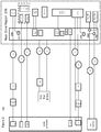
- FIG. 1 shows a rear zone architecture 100 without the features described herein.
- a rear zone architecture 100 includes a body controller 102, (this may also be referred to as a smart junction box or a body computer box), a rear vent switch 104, and a rear zone region 106.
- the body controller 102 may be located in the front of the vehicle.
- the rear zone region 106 may be associated and/or located in the rear of the vehicle such as in for example, the liftgate.
- the body controller 102 includes relay drives (RD) 110 and 112, a lock door relay (LD) 114, an unlock door relay (ULD) 116, and a controller area network (CAN) 118.
- RD relay drives
- LD lock door relay
- ULD unlock door relay
- CAN controller area network
- the rear zone region 106 includes a rear defogger (Rr Dfg) 120 tied to ground 122, an activator with lock 124 and unlock 126 functions, an unlock module 126, a liftgate (L/G) lock activation for non-power liftgate 128, a power liftgate (PLG) electronic control unit (ECU) 130, a L/G latch 132, a L/G chime 134, a L/G drive unit 136, a rear wiper 138 tied to ground 139, a rear vent motor 1 140 and rear vent motor 2 142, (e.g., left hand vent and right hand vent).
- Rr Dfg rear defogger
- PPG power liftgate
- the PLG ECU 130 includes double pole double through (DPDT) relays 144 and 146, metal-oxide-semiconductor field-effect transistor (mosfets) (F) 148 and 150, a high side driver (HSD) 152 and a CAN 154, which in connected to the CAN 118 in body controller 102.
- a PLG 160 is connected to the rear zone region 106 through a fuse 162 and power and ground 164 is provided to the rear zone region 106 through 16 gauge wires 166 and 168, respectively.
- the body controller 102 and rear zone region 106 are connected using relays, fuses and certain gauge wires as further described herein.
- the RD 110 is connected to the Rr Dfg 120 through a rear defogger relay (Rr DFG Rly) 170, a fuse 172 and using 12 gauge wires 174.
- the LD 114 and ULD 116 are connected to the Lock 124 and Unlock 126 using 16 gauge wires 176 and 178, respectively.
- the Rr Wpr 138 is connected to the body controller using 22 gauge wires 180 and to the RD 112 through rear wiper relay (Rr Wpr Rly) 182, a fuse 184 and using 16 gauge wires 186.
- the rear vent switch 104 is connected to the rear vent motor 1 140 and rear vent motor 2 142 through ports 188 and 190 using 16 gauge wires 192 and 194, respectively.
- Described herein is a rear zone module (RZM) that provides optimization of other electronic control modules (ECMs) in the vehicle, reduces mass, and provides system cost savings. Described also is an innovative use of input/output (I/O) sharing and power moding, energy savings, wiring simplification and cost savings.
- the RZM is one of many ECMs in a vehicle.
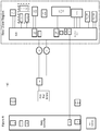
- FIG. 2 shows a first phase rear zone architecture 200 where a PLG ECU 230 now encompasses certain aspects of the rear zone region 206 and now becomes a rear zone ECU or rear zone module 230.
- rear zone ECU 230 now includes ground 222, ground 239, and ports 288 and 290.
- the remainder of the first phase rear zone architecture 200 is the same as rear zone architecture 100.
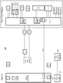
- Figure 3 shows a second phase rear zone architecture 300 where certain aspects of the relays, fuses and wire gauges are to be eliminated as shown by the dashed lines.
- Figure 4 shows a third phase rear zone architecture 400 where the items identified in Figure 3 are eliminated.
- the ground 222, ground 239, and ports 288 and 290 of Figure 2 are now incorporated into the rear zone ECU 430.
- FIG. 5 shows a fourth phase rear zone architecture 500 where a rear vent switch 504 is now incorporated into a drivers door switch (DDS) 507 and connected to a rear zone ECU 530 via a driver door module 509.
- DDS drivers door switch
- the driver door module 509 is tied to a wire 513 connecting CAN 512 to CAN 554.
- Figure 6 shows a fifth phase rear zone architecture 600 where the rear delays 110 and 112, rear defogger relay 120, and rear wiper relay 282 are now in a rear zone ECU 630 and a gauge of wires 666 and 668 are increased from 14 gauge to 12 gauge to handle the new current load.
- I/O optimization/operation moding is described herein.
- Properly managing the operation of the high current systems allows for optimization.
- the heated back window and rear wiper operation is disabled during PLG operation, (which may last for approximately 5-7 seconds). That is, the PLG operation and heated back window and rear wiper operations are mutually exclusive. Although this has no impact on the customer, it allows the gauge of the wires to be optimized.
- I/O optimization may be achieved wherein the RZM has several outputs and operation moding allows the sharing of the outputs to reduce the number of discrete drivers as shown for example, in part, by Figure 9 , and by comparing Figure 1 to Figure 6 .
- Figure 9 shows an example circuit 900 for operation moding where rear wiper motor is on, latch motor is off, heated back window is off and PLG motor is off.
- a portion of circuit 900, circuit 902, is included in rear zone ECU 630 of Figure 6 .
- Circuit 900 further includes a PLG subcircuit 905 connected to a subcircuit 907, which includes a heated back window subcircuit 910 and a rear wiper subcircuit 915.
- the PLG subcircuit 905 has a three way switch 920 and also includes a latch 930 with a switch 932.
- the three way switch 920 has a pole A connected to ground 922 and the heated back window subcircuit 910 and a rear wiper subcircuit 915.
- a PLG motor 940 is connected between pole B and pole C, which are both tied to ground 948.
- the latch 930 is connected between pole D and pole E of switch 932, both of which are tied to power.
- a heated back window subcircuit 910 is connected to pole A and to pole C, both of which are connected to ground.
- the rear window wiper subcircuit 915 includes a motor 970 connected between pole A and pole E. As implemented, the PLG 940, the latch 930, and the heated back window 910 are off and have no current flow running. The rear wiper motor 970 is on with the current running in direction Z2.
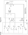
- Figure 10 shows an example circuit 1000 for operation moding where rear wiper motor is on, latch motor is off, heated back window is off and PLG motor is off.
- a portion of circuit 1000, circuit 1002, is included in rear zone ECU 630 of Figure 6 .
- Circuit 1000 further includes a PLG subcircuit 1005 connected to a subcircuit 1007, which includes a heated back window subcircuit 1010 and a rear wiper subcircuit 1015.
- the PLG subcircuit 1005 has a three way switch 1020 and also includes a latch 1030 with a switch 1032.
- the three way switch 1020 has a pole A connected to power and the heated back window subcircuit 1010 and a rear wiper subcircuit 1015.
- a PLG motor 1040 is connected between pole B and pole C, which are both tied to power.
- the latch 1030 is connected between pole D and pole E of switch 1032, both of which are tied to ground 1056.
- a heated back window subcircuit 1010 is connected to pole A and to pole C, both of which are connected to power.
- the rear window wiper subcircuit 1015 includes a rear wiper motor 1070 connected between pole A and pole E. As implemented, the PLG 1040, the latch 1030, and the heated back window 1010 are off and have no current flow running. The rear wiper motor 1070 is on with the current running in direction Z1.
- Figure 11 shows an example circuit 1100 for operation moding where rear wiper motor is on, latch motor is off, heated back window is on and PLG motor is off.
- a portion of circuit 1100, circuit 1102, is included in rear zone ECU 630 of Figure 6 .
- Circuit 1100 further includes a PLG subcircuit 1105 connected to a subcircuit 1107, which includes a heated back window subcircuit 1110 and a rear wiper subcircuit 1115.
- the PLG subcircuit 1105 has a three way switch 1120 and also includes a latch 1130 with a switch 1132.
- the three way switch 1120 has a pole A connected to power and the heated back window subcircuit 1110 and a rear wiper subcircuit 1115.
- a PLG motor 1140 is connected between pole B and pole C, which are both tied to ground 1148.
- the latch 1130 is connected between pole D and pole E of switch 1132, both of which are tied to ground 1156.
- a heated back window subcircuit 1110 is connected to pole A and to pole C, which is connected to ground 1148.
- the rear window wiper subcircuit 1115 includes a motor 1170 connected between pole A and pole E. As implemented, the PLG 1140, and the latch 1130 are off and have no current flow running. The heated back window 1110 and the rear window wiper circuit 1170 are on with the current running in direction Z1.
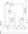
- Figure 12 shows an example circuit 1200 for operation moding where rear wiper motor is off, latch motor is off, heated back window is off and PLG motor is on.
- a portion of circuit 1200, circuit 1202, is included in rear zone ECU 630 of Figure 6 .
- Circuit 1200 further includes a PLG subcircuit 1205 connected to a subcircuit 1207, which includes a heated back window subcircuit 1210 and a rear wiper subcircuit 1215.
- the PLG subcircuit 1205 has a three way switch 1220 and also includes a latch 1230 with a switch 1232.
- the three way switch 1220 has a pole A connected to ground 1222 and the heated back window subcircuit 1210 and a rear wiper subcircuit 1215.
- a PLG motor 1240 is connected between pole B and pole C, where pole B is connected to power and pole C is connected to ground 1248.
- the latch 1230 is connected between pole D and pole E of switch 1232, both of which are tied to ground 1256.
- a heated back window subcircuit 1210 is connected to pole A and to pole C.
- the rear window wiper subcircuit 1215 includes a motor 1270 connected between pole A and pole E. As implemented, the heated back window 1210, the rear window motor 1270, and the latch 1230 are off and have no current flow running.
- the PLG 1240 is on with the current running in direction X1.
- Figure 13 shows an example circuit 1300 for operation moding where rear wiper motor is off, latch motor is off, heated back window is off and PLG motor is on.
- a portion of circuit 1300, circuit 1302, is included in rear zone ECU 630 of Figure 6 .
- Circuit 1300 further includes a PLG subcircuit 1305 connected to a subcircuit 1307, which includes a heated back window subcircuit 1310 and a rear wiper subcircuit 1315.
- the PLG subcircuit 1305 has a three way switch 1320 and also includes a latch 1330 with a switch 1332.
- the three way switch 1320 has a pole A connected to power and the heated back window subcircuit 1310 and a rear wiper subcircuit 1315.
- a PLG motor 1340 is connected between pole B and pole C, where pole B is connected to ground 1348 and pole C is connected to power.
- the latch 1330 is connected between pole D and pole E of switch 1332, both of which are tied to power.
- a heated back window subcircuit 1310 is connected to pole A and to pole C.
- the rear window wiper subcircuit 1315 includes a motor 1370 connected between pole A and pole E. As implemented, the heated back window 1310, the rear window motor 1370, and the latch 1330 are off and have no current flow running.
- the PLG 1340 is on with the current running in direction X2.
- Figure 14 shows an example circuit 1400 for operation moding where rear wiper motor is off, latch motor is on, heated back window is off and PLG motor is off.
- a portion of circuit 1400, circuit 1402, is included in rear zone ECU 630 of Figure 6 .
- Circuit 1400 further includes a PLG subcircuit 1405 connected to a subcircuit 1407, which includes a heated back window subcircuit 1410 and a rear wiper subcircuit 1415.
- the PLG subcircuit 1405 has a three way switch 1420 and also includes a latch 1430 with a switch 1432.
- the three way switch 1420 has a pole A connected to ground 1422 and the heated back window subcircuit 1410 and a rear wiper subcircuit 1415.
- a PLG motor 1440 is connected between pole B and pole C, both of which are connected to ground 1448.
- the latch 1430 is connected between pole D and pole E of switch 1432, where pole D is connected to power and pole E is connected to ground 1456.
- a heated back window subcircuit 1410 is connected to pole A and to pole C.
- the rear window wiper subcircuit 1415 includes a motor 1470 connected between pole A and pole E. As implemented, the heated back window 1410, the rear window wiper motor 1470, and the PLG 1440 are off and have no current flow running.
- the latch 1430 is on with the current running in direction Y1.
- Figure 15 shows an example circuit 1500 for operation moding where rear wiper motor is off, latch motor is on, heated back window is off and PLG motor is off.
- a portion of circuit 1500, circuit 1502, is included in rear zone ECU 630 of Figure 6 .
- Circuit 1500 further includes a PLG subcircuit 1505 connected to a subcircuit 1507, which includes a heated back window subcircuit 1510 and a rear wiper subcircuit 1515.
- the PLG subcircuit 1505 has a three way switch 1520 and also includes a latch 1530 with a switch 1532.
- the three way switch 1520 has a pole A connected to power and the heated back window subcircuit 1510 and a rear wiper subcircuit 1515.
- a PLG motor 1540 is connected between pole B and pole C, both of which are connected to power.
- the latch 1530 is connected between pole D and pole E of switch 1532, where pole D is connected to ground 1556 and pole E is connected to power.
- a heated back window subcircuit 1510 is connected to pole A and to pole C.
- the rear window wiper subcircuit 1515 includes a motor 1570 connected between pole A and pole E. As implemented, the heated back window 1510, the rear window wiper motor 1570, and the PLG 1540 are off and have no current flow running.
- the latch 1530 is on with the current running in direction Y2.
- a vehicle in general, includes a rear zone module (RZM) that includes at least a power liftgate (PLG) module, heated back window module, and a rear window wiper module.
- the vehicle further includes a controller configured to selectively control current with respect to at least the PLG module, heated back window module, and a rear window wiper module.
- the interconnections between the RZM and controller are minimized by sharing the interconnections as the PLG module operates mutually exclusively from the heated back window and rear window wiper module.
- the PLG module is off and at least one of the heated back window and rear window wiper module are on.
- the rear window wiper module has multiple on configurations.
- the vehicle may further include a latch module.
- the heated back window module, and a rear window wiper module are off and at most one of the PLG module and the latch module is on.
- the PLG module has multiple on configurations and in another case, the latch module has multiple on configurations.
Landscapes
- Engineering & Computer Science (AREA)
- Mechanical Engineering (AREA)
- Automation & Control Theory (AREA)
- Human Computer Interaction (AREA)
- Transportation (AREA)
- Control Of Multiple Motors (AREA)
- Power-Operated Mechanisms For Wings (AREA)
- Window Of Vehicle (AREA)
Claims (4)
- Fahrzeug, umfassend:ein Heckbereichsmodul (HBM), das mindestens eine Teilschaltung (905) für eine motorisch angetriebenen Heckklappe (MAH), eine Teilschaltung (910) für eine beheizte Heckscheibe, eine Teilschaltung (915) für einen Heckscheibenwischer und ein Schaltschloss (930) beinhaltet;eine Schaltung (902) in dem Heckbereichsmodul, die dafür ausgelegt ist, die MAH-Teilschaltung jeweils unter Ausschluss von der Teilschaltung für die beheizte Heckscheibe und der Teilschaltung für den Heckscheibenwischer zu betreiben, weshalb die Teilschaltung für die beheizte Heckscheibe und die Teilschaltung für den Heckscheibenwischer während eines Betriebs der MAH-Teilschaltung deaktiviert sind, wobei die Schaltung umfasst: einen ersten (A), zweiten (B), dritten (C), vierten (D) und fünften (E) Pol, wobei jeder Pol entweder mit der Stromversorgung oder Masse (922, 948, 1056) verbunden sein kann, einen Dreiwegeschalter (920), der A, B und C umfasst, und einen Zweiwegeschalter (932), der D und E umfasst, wobei die MAH zwischen B und C angeschlossen ist, die Teilschaltung für die beheizte Heckscheibe zwischen A und C angeschlossen ist, die Teilschaltung für den Heckscheibenwischer zwischen A und E angeschlossen ist und das Schaltschloss zwischen D und E angeschlossen ist; undeine Steuerung (102), die dafür ist, einen Strom in Bezug auf die MAH-Teilschaltung, die Teilschaltung für die beheizte Heckscheibe und eine Teilschaltung für den Heckscheibenwischer selektiv zu steuern, und die dafür ausgelegt ist, den Strom derart selektiv zu steuern, dass höchstens eines von der MAH-Teilschaltung und dem Schaltschloss eingeschaltet ist, wobei Verbindungen zwischen dem HBM und der Steuerung durch gemeinsame Nutzung der Verbindungen minimiert werden.
- Fahrzeug nach Anspruch 1, wobei die Steuerung dafür ausgelegt ist, den Strom derart selektiv zu steuern, dass mindestens eine von der Teilschaltung für die beheizte Heckscheibe und der Teilschaltung für den Heckscheibenwischer eingeschaltet ist.
- Fahrzeug nach Anspruch 2, wobei die Teilschaltung für den Heckscheibenwischer mehrere Konfigurationen aufweist.
- Verfahren zum Steuern von Fahrzeugoperationen, umfassend:Bereitstellen eines Heckbereichsmoduls (HBM), das mindestens eine Teilschaltung für eine motorisch angetriebenen Heckklappe (MAH), eine Teilschaltung (910) für eine beheizte Heckscheibe, eine Teilschaltung (915) für einen Heckscheibenwischer und ein Schaltschloss (930) beinhaltet,Bereitstellen einer Schaltung (902), umfassend einen ersten (A), zweiten (B), dritten (C), vierten (D) und fünften (E) Pol, wobei jeder Pol entweder mit der Stromversorgung oder der Masse (922, 948, 1056) verbunden werden kann, einen Dreiwegeschalter (920), der A, B und C umfasst, und einen Zweiwegeschalter (932), der D und E umfasst, wobei die MAH zwischen B und C angeschlossen ist, die Teilschaltung für die beheizte Heckscheibe zwischen A und C angeschlossen ist, die Teilschaltung für den Heckscheibenwischer zwischen A und E angeschlossen ist und das Schaltschloss zwischen D und E angeschlossen ist, sodass die MAH-Teilschaltung unter jeweiligem Ausschluss der Teilschaltung für die beheizte Heckscheibe und der Teilschaltung für den Heckscheibenwischer arbeitet, weshalb die Teilschaltung für die beheizte Heckscheibe und die Teilschaltung für den Heckscheibenwischer während eines Betriebs der MAH-Teilschaltung deaktiviert werden; undselektives Steuern eines Stroms in Bezug auf die MAH-Teilschaltung, die Teilschaltung für die beheizte Heckscheibe und eine Teilschaltung für den Heckscheibenwischer, und selektives Steuern des Stroms derart, dass höchstens eines von der MAH-Teilschaltung und dem Schaltschloss eingeschaltet ist, wobei Verbindungen zwischen dem HBM und der Steuerung durch gemeinsame Nutzung der Verbindungen minimiert werden.
Applications Claiming Priority (2)
| Application Number | Priority Date | Filing Date | Title |
|---|---|---|---|
| US201261612033P | 2012-03-16 | 2012-03-16 | |
| PCT/US2013/032340 WO2013138761A1 (en) | 2012-03-16 | 2013-03-15 | Rear zone module and rear zone controller |
Publications (2)
| Publication Number | Publication Date |
|---|---|
| EP2825418A1 EP2825418A1 (de) | 2015-01-21 |
| EP2825418B1 true EP2825418B1 (de) | 2019-07-17 |
Family
ID=48096193
Family Applications (1)
| Application Number | Title | Priority Date | Filing Date |
|---|---|---|---|
| EP13716515.5A Active EP2825418B1 (de) | 2012-03-16 | 2013-03-15 | Heckbereichsmodul und heckbreichssteuergerät |
Country Status (5)
| Country | Link |
|---|---|
| US (1) | US9610956B2 (de) |
| EP (1) | EP2825418B1 (de) |
| JP (1) | JP6306563B2 (de) |
| CN (1) | CN104321225B (de) |
| WO (1) | WO2013138761A1 (de) |
Families Citing this family (1)
| Publication number | Priority date | Publication date | Assignee | Title |
|---|---|---|---|---|
| CN109270922B (zh) * | 2018-10-30 | 2024-11-22 | 河南天海电器有限公司 | 自我诊断及自我控制的汽车电子式电源分配单元 |
Family Cites Families (25)
| Publication number | Priority date | Publication date | Assignee | Title |
|---|---|---|---|---|
| JPS59232320A (ja) * | 1983-06-15 | 1984-12-27 | Matsushita Electric Works Ltd | カメラ遠隔コントロ−ル装置 |
| DE3730468A1 (de) * | 1987-09-08 | 1989-03-16 | Bergmann Kabelwerke Ag | Bordnetz fuer kraftfahrzeuge und verfahren zum betrieb des bordnetzes |
| JPH0814216B2 (ja) * | 1991-03-29 | 1996-02-14 | 株式会社大井製作所 | 自動車用バックドアのクロージャ装置 |
| US6449798B1 (en) | 1991-10-09 | 2002-09-17 | Lear Corporation | Multi-function apparatus having flexible clutch |
| US5519258A (en) * | 1993-11-22 | 1996-05-21 | Ford Motor Company | System and method for controlling vehicle lift gate window wiper |
| JP3144453B2 (ja) * | 1994-03-23 | 2001-03-12 | 矢崎総業株式会社 | スイッチ判別機能を備えたスイッチ装置及び操作用スイッチ |
| US5764010A (en) * | 1995-04-28 | 1998-06-09 | United Technologies Automotive, Inc. | Control system for an automotive vehicle multi-functional apparatus |
| US5916327A (en) * | 1995-04-28 | 1999-06-29 | Ut Automotive Dearborn, Inc. | Multi-functional apparatus employing an electromagnetic device |
| US6111378A (en) * | 1995-04-28 | 2000-08-29 | Ut Automotive Dearborn, Inc. | Window wiper motor system for an automotive vehicle |
| JPH10119726A (ja) * | 1996-10-18 | 1998-05-12 | Nissan Shatai Co Ltd | ワイパー及び開閉体の制御装置 |
| JP3338328B2 (ja) * | 1997-04-21 | 2002-10-28 | 株式会社日立製作所 | 乗物の電力供給装置 |
| US5847519A (en) * | 1997-10-09 | 1998-12-08 | Ut Automotive Dearborn, Inc. | Multi-functional apparatus for a wiper and cable drive |
| JP2000229545A (ja) * | 1999-02-09 | 2000-08-22 | Hitachi Ltd | 車両配線装置 |
| JP2000247192A (ja) * | 1999-02-24 | 2000-09-12 | Sumitomo Wiring Syst Ltd | 自動車のバックドアにおけるガラスハッチへのワイヤハーネス配索構造 |
| US6174016B1 (en) * | 1999-10-15 | 2001-01-16 | Valeo Electrical Systems, Inc. | Door assembly module and method |
| US6700795B1 (en) * | 2002-01-23 | 2004-03-02 | Yazaki North America | Scalable, modular architecture for automotive power distribution and body control functions |
| DE10300464A1 (de) * | 2003-01-07 | 2004-07-15 | Intedis Gmbh & Co. Kg | Bordnetz eines Kraftfahrzeugs |
| US7042363B2 (en) * | 2003-04-02 | 2006-05-09 | General Motors Corporation | Methods and apparatus for producing a three-state single wire control |
| JP3808864B2 (ja) * | 2003-12-03 | 2006-08-16 | 株式会社ケーヒン | 協調制御装置 |
| US20070274695A1 (en) * | 2006-05-26 | 2007-11-29 | John Phillip Chevalier | Automotive universal latch control implementation |
| US7479748B2 (en) * | 2006-10-25 | 2009-01-20 | Robert Bosch Gmbh | Systems and methods of tracking partition system performance |
| JP2008296871A (ja) * | 2007-06-04 | 2008-12-11 | Auto Network Gijutsu Kenkyusho:Kk | 統合電子制御装置 |
| US8875442B2 (en) * | 2010-03-16 | 2014-11-04 | Strattec Power Access Llc | Method and apparatus of active dampening a powered closure system |
| JP5750282B2 (ja) * | 2011-03-29 | 2015-07-15 | 株式会社ケーヒン | 電子制御装置 |
| US8585118B2 (en) * | 2011-06-23 | 2013-11-19 | Gm Global Technology Operation Llc | Integral power tailgate and wiper actuation in a vehicle |
-
2013
- 2013-03-15 US US13/837,157 patent/US9610956B2/en not_active Expired - Fee Related
- 2013-03-15 WO PCT/US2013/032340 patent/WO2013138761A1/en not_active Ceased
- 2013-03-15 JP JP2015500665A patent/JP6306563B2/ja not_active Expired - Fee Related
- 2013-03-15 EP EP13716515.5A patent/EP2825418B1/de active Active
- 2013-03-15 CN CN201380014579.0A patent/CN104321225B/zh not_active Expired - Fee Related
Non-Patent Citations (1)
| Title |
|---|
| None * |
Also Published As
| Publication number | Publication date |
|---|---|
| US9610956B2 (en) | 2017-04-04 |
| JP6306563B2 (ja) | 2018-04-04 |
| JP2015510852A (ja) | 2015-04-13 |
| CN104321225B (zh) | 2016-10-26 |
| EP2825418A1 (de) | 2015-01-21 |
| CN104321225A (zh) | 2015-01-28 |
| US20130245885A1 (en) | 2013-09-19 |
| WO2013138761A1 (en) | 2013-09-19 |
Similar Documents
| Publication | Publication Date | Title |
|---|---|---|
| US20110063708A1 (en) | Control device for at least one electrochromic window, control system for one or more electrochromic windows, means of transport with at least one electrochromic window and with at least one control device, and method of | |
| EP2982573A2 (de) | Fahrzeugvorderstruktur | |
| US9862342B2 (en) | Vehicular emergency alert device | |
| US20180176305A1 (en) | In-vehicle network system | |
| CN102060056A (zh) | 商用车的带有中间车顶模块的驾驶室 | |
| EP2578780A1 (de) | Stromversorgungs-steuervorrichtung für elektrische aktuatoren für türzubehörteile von automobilen | |
| CN105539325A (zh) | 一种汽车儿童锁控制装置 | |
| US8918249B2 (en) | Dual function electronic control unit | |
| US9610956B2 (en) | Rear zone module and rear zone controller | |
| CN114103836B (zh) | 多域控制车载系统以及汽车 | |
| US20130179033A1 (en) | Vehicle control circuit | |
| US9834177B2 (en) | Method for programming a wiper system for vehicle windscreens and wiper system | |
| US20080288137A1 (en) | Vehicle-Mounted Load Drive Control System | |
| US11518221B2 (en) | Cable reinforcement for vehicle doors | |
| JP2016088242A (ja) | 車載機器制御システム | |
| CN101155716A (zh) | 车载通信装置及其方法 | |
| JP5246059B2 (ja) | 車載用電子制御ユニットの搭載位置決定方法 | |
| CN209249837U (zh) | 一种车辆及其车用集线器 | |
| US20050040969A1 (en) | Actuator unit and actuator control system for a motor vehicle | |
| EP4414217B1 (de) | Fahrzeuglampe, steuerungsvorrichtung und steuerungsverfahren für fahrzeuglampe | |
| CN104691478A (zh) | 一种基于汽车外气囊的减少汽车翻滚的系统 | |
| JP5246058B2 (ja) | 車載用電子制御ユニットの搭載位置決定方法 | |
| GB2626798A (en) | On-board vehicle communication system | |
| KR20140087367A (ko) | 도어 드라이브 모듈 및 이를 적용한 도어 제어 장치 | |
| WO2015084277A1 (en) | A door control system |
Legal Events
| Date | Code | Title | Description |
|---|---|---|---|
| PUAI | Public reference made under article 153(3) epc to a published international application that has entered the european phase |
Free format text: ORIGINAL CODE: 0009012 |
|
| 17P | Request for examination filed |
Effective date: 20141015 |
|
| AK | Designated contracting states |
Kind code of ref document: A1 Designated state(s): AL AT BE BG CH CY CZ DE DK EE ES FI FR GB GR HR HU IE IS IT LI LT LU LV MC MK MT NL NO PL PT RO RS SE SI SK SM TR |
|
| AX | Request for extension of the european patent |
Extension state: BA ME |
|
| DAX | Request for extension of the european patent (deleted) | ||
| STAA | Information on the status of an ep patent application or granted ep patent |
Free format text: STATUS: EXAMINATION IS IN PROGRESS |
|
| 17Q | First examination report despatched |
Effective date: 20170310 |
|
| GRAJ | Information related to disapproval of communication of intention to grant by the applicant or resumption of examination proceedings by the epo deleted |
Free format text: ORIGINAL CODE: EPIDOSDIGR1 |
|
| STAA | Information on the status of an ep patent application or granted ep patent |
Free format text: STATUS: GRANT OF PATENT IS INTENDED |
|
| GRAP | Despatch of communication of intention to grant a patent |
Free format text: ORIGINAL CODE: EPIDOSNIGR1 |
|
| GRAJ | Information related to disapproval of communication of intention to grant by the applicant or resumption of examination proceedings by the epo deleted |
Free format text: ORIGINAL CODE: EPIDOSDIGR1 |
|
| STAA | Information on the status of an ep patent application or granted ep patent |
Free format text: STATUS: EXAMINATION IS IN PROGRESS |
|
| GRAP | Despatch of communication of intention to grant a patent |
Free format text: ORIGINAL CODE: EPIDOSNIGR1 |
|
| STAA | Information on the status of an ep patent application or granted ep patent |
Free format text: STATUS: GRANT OF PATENT IS INTENDED |
|
| INTG | Intention to grant announced |
Effective date: 20190201 |
|
| INTC | Intention to grant announced (deleted) | ||
| RAP1 | Party data changed (applicant data changed or rights of an application transferred) |
Owner name: FLEXTRONICS AP, LLC |
|
| INTG | Intention to grant announced |
Effective date: 20190219 |
|
| GRAS | Grant fee paid |
Free format text: ORIGINAL CODE: EPIDOSNIGR3 |
|
| GRAA | (expected) grant |
Free format text: ORIGINAL CODE: 0009210 |
|
| STAA | Information on the status of an ep patent application or granted ep patent |
Free format text: STATUS: THE PATENT HAS BEEN GRANTED |
|
| AK | Designated contracting states |
Kind code of ref document: B1 Designated state(s): AL AT BE BG CH CY CZ DE DK EE ES FI FR GB GR HR HU IE IS IT LI LT LU LV MC MK MT NL NO PL PT RO RS SE SI SK SM TR |
|
| REG | Reference to a national code |
Ref country code: GB Ref legal event code: FG4D |
|
| REG | Reference to a national code |
Ref country code: CH Ref legal event code: EP |
|
| REG | Reference to a national code |
Ref country code: DE Ref legal event code: R096 Ref document number: 602013057878 Country of ref document: DE |
|
| REG | Reference to a national code |
Ref country code: IE Ref legal event code: FG4D |
|
| REG | Reference to a national code |
Ref country code: AT Ref legal event code: REF Ref document number: 1155563 Country of ref document: AT Kind code of ref document: T Effective date: 20190815 |
|
| REG | Reference to a national code |
Ref country code: NL Ref legal event code: MP Effective date: 20190717 |
|
| REG | Reference to a national code |
Ref country code: LT Ref legal event code: MG4D |
|
| REG | Reference to a national code |
Ref country code: AT Ref legal event code: MK05 Ref document number: 1155563 Country of ref document: AT Kind code of ref document: T Effective date: 20190717 |
|
| PG25 | Lapsed in a contracting state [announced via postgrant information from national office to epo] |
Ref country code: LT Free format text: LAPSE BECAUSE OF FAILURE TO SUBMIT A TRANSLATION OF THE DESCRIPTION OR TO PAY THE FEE WITHIN THE PRESCRIBED TIME-LIMIT Effective date: 20190717 Ref country code: FI Free format text: LAPSE BECAUSE OF FAILURE TO SUBMIT A TRANSLATION OF THE DESCRIPTION OR TO PAY THE FEE WITHIN THE PRESCRIBED TIME-LIMIT Effective date: 20190717 Ref country code: SE Free format text: LAPSE BECAUSE OF FAILURE TO SUBMIT A TRANSLATION OF THE DESCRIPTION OR TO PAY THE FEE WITHIN THE PRESCRIBED TIME-LIMIT Effective date: 20190717 Ref country code: HR Free format text: LAPSE BECAUSE OF FAILURE TO SUBMIT A TRANSLATION OF THE DESCRIPTION OR TO PAY THE FEE WITHIN THE PRESCRIBED TIME-LIMIT Effective date: 20190717 Ref country code: NO Free format text: LAPSE BECAUSE OF FAILURE TO SUBMIT A TRANSLATION OF THE DESCRIPTION OR TO PAY THE FEE WITHIN THE PRESCRIBED TIME-LIMIT Effective date: 20191017 Ref country code: BG Free format text: LAPSE BECAUSE OF FAILURE TO SUBMIT A TRANSLATION OF THE DESCRIPTION OR TO PAY THE FEE WITHIN THE PRESCRIBED TIME-LIMIT Effective date: 20191017 Ref country code: PT Free format text: LAPSE BECAUSE OF FAILURE TO SUBMIT A TRANSLATION OF THE DESCRIPTION OR TO PAY THE FEE WITHIN THE PRESCRIBED TIME-LIMIT Effective date: 20191118 Ref country code: NL Free format text: LAPSE BECAUSE OF FAILURE TO SUBMIT A TRANSLATION OF THE DESCRIPTION OR TO PAY THE FEE WITHIN THE PRESCRIBED TIME-LIMIT Effective date: 20190717 Ref country code: AT Free format text: LAPSE BECAUSE OF FAILURE TO SUBMIT A TRANSLATION OF THE DESCRIPTION OR TO PAY THE FEE WITHIN THE PRESCRIBED TIME-LIMIT Effective date: 20190717 |
|
| PG25 | Lapsed in a contracting state [announced via postgrant information from national office to epo] |
Ref country code: ES Free format text: LAPSE BECAUSE OF FAILURE TO SUBMIT A TRANSLATION OF THE DESCRIPTION OR TO PAY THE FEE WITHIN THE PRESCRIBED TIME-LIMIT Effective date: 20190717 Ref country code: AL Free format text: LAPSE BECAUSE OF FAILURE TO SUBMIT A TRANSLATION OF THE DESCRIPTION OR TO PAY THE FEE WITHIN THE PRESCRIBED TIME-LIMIT Effective date: 20190717 Ref country code: LV Free format text: LAPSE BECAUSE OF FAILURE TO SUBMIT A TRANSLATION OF THE DESCRIPTION OR TO PAY THE FEE WITHIN THE PRESCRIBED TIME-LIMIT Effective date: 20190717 Ref country code: IS Free format text: LAPSE BECAUSE OF FAILURE TO SUBMIT A TRANSLATION OF THE DESCRIPTION OR TO PAY THE FEE WITHIN THE PRESCRIBED TIME-LIMIT Effective date: 20191117 Ref country code: RS Free format text: LAPSE BECAUSE OF FAILURE TO SUBMIT A TRANSLATION OF THE DESCRIPTION OR TO PAY THE FEE WITHIN THE PRESCRIBED TIME-LIMIT Effective date: 20190717 Ref country code: GR Free format text: LAPSE BECAUSE OF FAILURE TO SUBMIT A TRANSLATION OF THE DESCRIPTION OR TO PAY THE FEE WITHIN THE PRESCRIBED TIME-LIMIT Effective date: 20191018 |
|
| PG25 | Lapsed in a contracting state [announced via postgrant information from national office to epo] |
Ref country code: TR Free format text: LAPSE BECAUSE OF FAILURE TO SUBMIT A TRANSLATION OF THE DESCRIPTION OR TO PAY THE FEE WITHIN THE PRESCRIBED TIME-LIMIT Effective date: 20190717 |
|
| PG25 | Lapsed in a contracting state [announced via postgrant information from national office to epo] |
Ref country code: EE Free format text: LAPSE BECAUSE OF FAILURE TO SUBMIT A TRANSLATION OF THE DESCRIPTION OR TO PAY THE FEE WITHIN THE PRESCRIBED TIME-LIMIT Effective date: 20190717 Ref country code: DK Free format text: LAPSE BECAUSE OF FAILURE TO SUBMIT A TRANSLATION OF THE DESCRIPTION OR TO PAY THE FEE WITHIN THE PRESCRIBED TIME-LIMIT Effective date: 20190717 Ref country code: PL Free format text: LAPSE BECAUSE OF FAILURE TO SUBMIT A TRANSLATION OF THE DESCRIPTION OR TO PAY THE FEE WITHIN THE PRESCRIBED TIME-LIMIT Effective date: 20190717 Ref country code: RO Free format text: LAPSE BECAUSE OF FAILURE TO SUBMIT A TRANSLATION OF THE DESCRIPTION OR TO PAY THE FEE WITHIN THE PRESCRIBED TIME-LIMIT Effective date: 20190717 |
|
| PG25 | Lapsed in a contracting state [announced via postgrant information from national office to epo] |
Ref country code: IS Free format text: LAPSE BECAUSE OF FAILURE TO SUBMIT A TRANSLATION OF THE DESCRIPTION OR TO PAY THE FEE WITHIN THE PRESCRIBED TIME-LIMIT Effective date: 20200224 Ref country code: SM Free format text: LAPSE BECAUSE OF FAILURE TO SUBMIT A TRANSLATION OF THE DESCRIPTION OR TO PAY THE FEE WITHIN THE PRESCRIBED TIME-LIMIT Effective date: 20190717 Ref country code: SK Free format text: LAPSE BECAUSE OF FAILURE TO SUBMIT A TRANSLATION OF THE DESCRIPTION OR TO PAY THE FEE WITHIN THE PRESCRIBED TIME-LIMIT Effective date: 20190717 Ref country code: CZ Free format text: LAPSE BECAUSE OF FAILURE TO SUBMIT A TRANSLATION OF THE DESCRIPTION OR TO PAY THE FEE WITHIN THE PRESCRIBED TIME-LIMIT Effective date: 20190717 |
|
| REG | Reference to a national code |
Ref country code: DE Ref legal event code: R097 Ref document number: 602013057878 Country of ref document: DE |
|
| PLBE | No opposition filed within time limit |
Free format text: ORIGINAL CODE: 0009261 |
|
| STAA | Information on the status of an ep patent application or granted ep patent |
Free format text: STATUS: NO OPPOSITION FILED WITHIN TIME LIMIT |
|
| PG2D | Information on lapse in contracting state deleted |
Ref country code: IS |
|
| 26N | No opposition filed |
Effective date: 20200603 |
|
| PG25 | Lapsed in a contracting state [announced via postgrant information from national office to epo] |
Ref country code: SI Free format text: LAPSE BECAUSE OF FAILURE TO SUBMIT A TRANSLATION OF THE DESCRIPTION OR TO PAY THE FEE WITHIN THE PRESCRIBED TIME-LIMIT Effective date: 20190717 |
|
| PG25 | Lapsed in a contracting state [announced via postgrant information from national office to epo] |
Ref country code: MC Free format text: LAPSE BECAUSE OF FAILURE TO SUBMIT A TRANSLATION OF THE DESCRIPTION OR TO PAY THE FEE WITHIN THE PRESCRIBED TIME-LIMIT Effective date: 20190717 |
|
| REG | Reference to a national code |
Ref country code: CH Ref legal event code: PL |
|
| REG | Reference to a national code |
Ref country code: BE Ref legal event code: MM Effective date: 20200331 |
|
| PG25 | Lapsed in a contracting state [announced via postgrant information from national office to epo] |
Ref country code: LU Free format text: LAPSE BECAUSE OF NON-PAYMENT OF DUE FEES Effective date: 20200315 |
|
| PG25 | Lapsed in a contracting state [announced via postgrant information from national office to epo] |
Ref country code: CH Free format text: LAPSE BECAUSE OF NON-PAYMENT OF DUE FEES Effective date: 20200331 Ref country code: IE Free format text: LAPSE BECAUSE OF NON-PAYMENT OF DUE FEES Effective date: 20200315 Ref country code: LI Free format text: LAPSE BECAUSE OF NON-PAYMENT OF DUE FEES Effective date: 20200331 |
|
| PG25 | Lapsed in a contracting state [announced via postgrant information from national office to epo] |
Ref country code: BE Free format text: LAPSE BECAUSE OF NON-PAYMENT OF DUE FEES Effective date: 20200331 |
|
| PG25 | Lapsed in a contracting state [announced via postgrant information from national office to epo] |
Ref country code: MT Free format text: LAPSE BECAUSE OF FAILURE TO SUBMIT A TRANSLATION OF THE DESCRIPTION OR TO PAY THE FEE WITHIN THE PRESCRIBED TIME-LIMIT Effective date: 20190717 Ref country code: CY Free format text: LAPSE BECAUSE OF FAILURE TO SUBMIT A TRANSLATION OF THE DESCRIPTION OR TO PAY THE FEE WITHIN THE PRESCRIBED TIME-LIMIT Effective date: 20190717 |
|
| PG25 | Lapsed in a contracting state [announced via postgrant information from national office to epo] |
Ref country code: MK Free format text: LAPSE BECAUSE OF FAILURE TO SUBMIT A TRANSLATION OF THE DESCRIPTION OR TO PAY THE FEE WITHIN THE PRESCRIBED TIME-LIMIT Effective date: 20190717 |
|
| PGFP | Annual fee paid to national office [announced via postgrant information from national office to epo] |
Ref country code: DE Payment date: 20240328 Year of fee payment: 12 Ref country code: GB Payment date: 20240319 Year of fee payment: 12 |
|
| PGFP | Annual fee paid to national office [announced via postgrant information from national office to epo] |
Ref country code: IT Payment date: 20240321 Year of fee payment: 12 Ref country code: FR Payment date: 20240327 Year of fee payment: 12 |
|
| REG | Reference to a national code |
Ref country code: DE Ref legal event code: R119 Ref document number: 602013057878 Country of ref document: DE |
|
| GBPC | Gb: european patent ceased through non-payment of renewal fee |
Effective date: 20250315 |
|
| PG25 | Lapsed in a contracting state [announced via postgrant information from national office to epo] |
Ref country code: DE Free format text: LAPSE BECAUSE OF NON-PAYMENT OF DUE FEES Effective date: 20251001 |
|
| PG25 | Lapsed in a contracting state [announced via postgrant information from national office to epo] |
Ref country code: GB Free format text: LAPSE BECAUSE OF NON-PAYMENT OF DUE FEES Effective date: 20250315 |
|
| PG25 | Lapsed in a contracting state [announced via postgrant information from national office to epo] |
Ref country code: FR Free format text: LAPSE BECAUSE OF NON-PAYMENT OF DUE FEES Effective date: 20250331 Ref country code: IT Free format text: LAPSE BECAUSE OF NON-PAYMENT OF DUE FEES Effective date: 20250315 |