EP2825083B1 - Staubsauger mit wasserbad - Google Patents
Staubsauger mit wasserbad Download PDFInfo
- Publication number
- EP2825083B1 EP2825083B1 EP13707152.8A EP13707152A EP2825083B1 EP 2825083 B1 EP2825083 B1 EP 2825083B1 EP 13707152 A EP13707152 A EP 13707152A EP 2825083 B1 EP2825083 B1 EP 2825083B1
- Authority
- EP
- European Patent Office
- Prior art keywords
- vacuum cleaner
- suction head
- fact
- accordance
- liquid container
- Prior art date
- Legal status (The legal status is an assumption and is not a legal conclusion. Google has not performed a legal analysis and makes no representation as to the accuracy of the status listed.)
- Active
Links
Images




Classifications
-
- A—HUMAN NECESSITIES
- A47—FURNITURE; DOMESTIC ARTICLES OR APPLIANCES; COFFEE MILLS; SPICE MILLS; SUCTION CLEANERS IN GENERAL
- A47L—DOMESTIC WASHING OR CLEANING; SUCTION CLEANERS IN GENERAL
- A47L5/00—Structural features of suction cleaners
- A47L5/12—Structural features of suction cleaners with power-driven air-pumps or air-compressors, e.g. driven by motor vehicle engine vacuum
- A47L5/22—Structural features of suction cleaners with power-driven air-pumps or air-compressors, e.g. driven by motor vehicle engine vacuum with rotary fans
- A47L5/36—Suction cleaners with hose between nozzle and casing; Suction cleaners for fixing on staircases; Suction cleaners for carrying on the back
- A47L5/365—Suction cleaners with hose between nozzle and casing; Suction cleaners for fixing on staircases; Suction cleaners for carrying on the back of the vertical type, e.g. tank or bucket type
-
- A—HUMAN NECESSITIES
- A01—AGRICULTURE; FORESTRY; ANIMAL HUSBANDRY; HUNTING; TRAPPING; FISHING
- A01G—HORTICULTURE; CULTIVATION OF VEGETABLES, FLOWERS, RICE, FRUIT, VINES, HOPS OR SEAWEED; FORESTRY; WATERING
- A01G7/00—Botany in general
- A01G7/06—Treatment of growing trees or plants, e.g. for preventing decay of wood, for tingeing flowers or wood, for prolonging the life of plants
-
- A—HUMAN NECESSITIES
- A47—FURNITURE; DOMESTIC ARTICLES OR APPLIANCES; COFFEE MILLS; SPICE MILLS; SUCTION CLEANERS IN GENERAL
- A47L—DOMESTIC WASHING OR CLEANING; SUCTION CLEANERS IN GENERAL
- A47L7/00—Suction cleaners adapted for additional purposes; Tables with suction openings for cleaning purposes; Containers for cleaning articles by suction; Suction cleaners adapted to cleaning of brushes; Suction cleaners adapted to taking-up liquids
- A47L7/0004—Suction cleaners adapted to take up liquids, e.g. wet or dry vacuum cleaners
- A47L7/0019—Details of the casing
-
- A—HUMAN NECESSITIES
- A47—FURNITURE; DOMESTIC ARTICLES OR APPLIANCES; COFFEE MILLS; SPICE MILLS; SUCTION CLEANERS IN GENERAL
- A47L—DOMESTIC WASHING OR CLEANING; SUCTION CLEANERS IN GENERAL
- A47L7/00—Suction cleaners adapted for additional purposes; Tables with suction openings for cleaning purposes; Containers for cleaning articles by suction; Suction cleaners adapted to cleaning of brushes; Suction cleaners adapted to taking-up liquids
- A47L7/0004—Suction cleaners adapted to take up liquids, e.g. wet or dry vacuum cleaners
- A47L7/0023—Recovery tanks
-
- A—HUMAN NECESSITIES
- A47—FURNITURE; DOMESTIC ARTICLES OR APPLIANCES; COFFEE MILLS; SPICE MILLS; SUCTION CLEANERS IN GENERAL
- A47L—DOMESTIC WASHING OR CLEANING; SUCTION CLEANERS IN GENERAL
- A47L9/00—Details or accessories of suction cleaners, e.g. mechanical means for controlling the suction or for effecting pulsating action; Storing devices specially adapted to suction cleaners or parts thereof; Carrying-vehicles specially adapted for suction cleaners
-
- A—HUMAN NECESSITIES
- A47—FURNITURE; DOMESTIC ARTICLES OR APPLIANCES; COFFEE MILLS; SPICE MILLS; SUCTION CLEANERS IN GENERAL
- A47L—DOMESTIC WASHING OR CLEANING; SUCTION CLEANERS IN GENERAL
- A47L9/00—Details or accessories of suction cleaners, e.g. mechanical means for controlling the suction or for effecting pulsating action; Storing devices specially adapted to suction cleaners or parts thereof; Carrying-vehicles specially adapted for suction cleaners
- A47L9/10—Filters; Dust separators; Dust removal; Automatic exchange of filters
- A47L9/106—Dust removal
-
- A—HUMAN NECESSITIES
- A47—FURNITURE; DOMESTIC ARTICLES OR APPLIANCES; COFFEE MILLS; SPICE MILLS; SUCTION CLEANERS IN GENERAL
- A47L—DOMESTIC WASHING OR CLEANING; SUCTION CLEANERS IN GENERAL
- A47L9/00—Details or accessories of suction cleaners, e.g. mechanical means for controlling the suction or for effecting pulsating action; Storing devices specially adapted to suction cleaners or parts thereof; Carrying-vehicles specially adapted for suction cleaners
- A47L9/10—Filters; Dust separators; Dust removal; Automatic exchange of filters
- A47L9/18—Liquid filters
-
- A—HUMAN NECESSITIES
- A47—FURNITURE; DOMESTIC ARTICLES OR APPLIANCES; COFFEE MILLS; SPICE MILLS; SUCTION CLEANERS IN GENERAL
- A47L—DOMESTIC WASHING OR CLEANING; SUCTION CLEANERS IN GENERAL
- A47L9/00—Details or accessories of suction cleaners, e.g. mechanical means for controlling the suction or for effecting pulsating action; Storing devices specially adapted to suction cleaners or parts thereof; Carrying-vehicles specially adapted for suction cleaners
- A47L9/32—Handles
- A47L9/327—Handles for suction cleaners with hose between nozzle and casing
Definitions
- the invention relates to vacuum cleaners, comprising: a liquid container; and a suction head removably attached to the liquid container in a first position relative to the liquid container.
- a water bath is used instead of the paper filter.
- the water is housed in a tank into which the sucked air flows.
- the tank is detachably attached to the vacuum cleaner housing, so that dirty water can be easily replaced.
- the water bath absorbs the dust and dirt particles and binds them.
- the cleaned air flows, usually via a separator, in the connected to the water tank suction head, in which the engine is housed, and is then discharged to the environment. Since dust and dirt are completely bound in the water, the discharged air is best cleaned. Health complaints caused by dust, dirt, dust mites u. ⁇ . Be triggered, can be prevented.
- the suction head of the vacuum device described therein is arranged in a first position relative to the collecting container removably on the collecting container.
- the vacuum apparatus includes a positioning member that is adjustable to position the suction head in a second position relative to the sump, the suction head, in the second position, being inclined relative to the first position by a first angle greater than 0 °.
- the inclined position is only the installation and locking of the suction head with the lid of the vacuum device by means of the positioning and represents the first steps of the preparation of the compound.
- the suction head is first placed on the positioning. Subsequently, the suction head is lowered down, the positioning pushed outward and locked. The positioning thus serves to lock the removable suction head on the rest of the vacuum cleaner housing.
- the US 2010/0139032 A1 describes a wet / dry vacuum vacuum cleaner with a removable receptacle.
- the vacuum cleaner comprises: a liquid container; and a suction head removably mounted to the liquid container in a first position relative to the liquid container, the vacuum cleaner having a positioning member that is adjustable to position the suction head in a second position relative to the liquid container, the suction head being in the second position is inclined relative to the first position by a first angle ( ⁇ ) greater than 0 °.
- the suction head has at least one housing and a suction motor arranged in the housing.
- a separator may be provided inside the housing. The sucked by the suction air is first fed through an inlet channel into the interior of the water tank. There, the air releases dirt and dust particles, which are bound in a water bath. Subsequently, the air (possibly via a separator) is sucked into the suction head and discharged from there to the environment.
- the suction head In the first position (working or deployed position), the suction head is attached to the container, e.g. by means of a latching mechanism, in the second position (parking position), the suction head is inclined on the container and the positioning element.
- the inclined position or oblique position relative to the horizontal causes water that has entered the engine head during operation of the "water vacuum cleaner", obliquely flows down and then drains into the container or drips.
- the suction head thus assumes, when it is removed, a defined parking or support position relative to the container. In this way, the drying of the suction head is accelerated and improved.
- the handling of the suction head is thus facilitated because it does not have to be removed from the container in a moist state for drying. It is only tilted onto the container.
- the suction head in particular the areas around the separator and the blower of the suction motor, can dry better. An accumulation of moisture (with negative consequences such as mold or odor) can be prevented.
- the first angle ( ⁇ ) is preferably between 3 ° and 15 °, in particular between 3 ° and 10 °. At these angles sufficient for drying drying is achieved, while stable position of the suction head on top of the container.
- the positioning element is designed in particular as a bracket.
- the positioning element is arranged pivotably on the liquid container.
- the bracket thus acts as the handle of the container, similar to the handle of a bucket, and can, in addition to its function as a positioning, also serve as a handle.
- the positioning element has at least one first setting position, which corresponds to the first position of the suction head, and a second setting position, which corresponds to the second position of the suction head.
- the correspondence of the positions means that in the first setting position of the positioning element the suction head is arranged in its first position (insertion position) on the container, in the second setting position of the positioning element the suction head is arranged in its second position (parking position) on the container or on the container Container rests.
- the positioning element is preferably fixable in the first setting position and / or in the second setting position by a locking mechanism, in particular by a latching mechanism.
- the mechanism is designed so that the positioning element retains its position under the influence of the weight of the suction head resting on the positioning element. Only when additional force from the outside acts on the positioning element, the locking / locking can be released and the positioning can be brought into the first setting position. This unlatching can be accomplished, for example, by exerting a force on the top of the suction head.
- the positioning element may have a third setting position, in which the positioning element can be used as a handle for transporting the liquid container. Locking or other fixing in this third setting position is also conceivable.
- the positioning element has, in particular, an edge facing the suction head, which in the first setting position is arranged parallel and / or flush with an upper edge of the wall bounding an upper opening of the liquid container.
- the positioning element has an edge facing the suction head, which in the second setting position is inclined by a second angle ( ⁇ ) greater than 0 ° with respect to an upper edge of the wall delimiting an upper opening of the liquid container.
- the upper edge is aligned in the intended use position of the container usually parallel to the ground.
- An inclination of the suction head thus represents an inclination of the suction head relative to the upper edge and the ground.
- the second angle ( ⁇ ) is preferably between 5 ° and 20 °, in particular between 6 ° and 15 °. There is a functional relationship between the first angle and the second angle.
- the suction head can have means for stably depositing the suction head on a flat surface. So the suction head can be stored in a stable position on the ground, when it is removed from the container. The position can be inclined so that the bottom of the housing (obliquely) facing upward, so no water can flow from the interior of the housing. An "intermediate storage" of the suction head, for example, for emptying the water tank, is thus made possible without polluting the environment by dripping (dirty) water.
- the suction head may have a carrier part for supporting the liquid container on the carrier part.
- the support member is usually designed as a movable pedestal.
- the carrier part preferably has a depression whose cross section corresponds to the cross section of the bottom surface of the liquid container.
- the support member may have rollers for movable support of the support member on the ground.
- the vacuum cleaner is thus movable on the ground overall.
- the invention relates as a result to a vacuum cleaner with a carrier part, a liquid tank and a suction head.
- a bracket is pivotally mounted, so that the bracket can serve as a positioning element for the suction head.
- the suction head can be arranged in a parking position, which is inclined relative to the upper edge of the tank by an angle ⁇ greater than 0 °, by the suction head rests on the bracket.
- the bracket is locked in the parking position with the container.
- FIG. 1 is a perspective view of the preferred embodiment of the vacuum cleaner according to the invention shown.
- the vacuum cleaner comprises three essential components, namely a carrier part 1, a liquid or water tank 2 and a suction head 3.
- the support part 1 has a main body 10 and rollers 11, which allow a comfortable method of the support member 1 on the ground.
- a recess 12 in which the tank 2 can be used accurately, so that the tank 2 is secured against lateral movements.
- the tank 2 has, as in the FIG. 5 shown, a side wall 20 and a bottom wall 21 which define an interior space 22.
- the interior 22 is at least partially filled with water when using the vacuum cleaner.
- the tank 2 has a connection element 23 for connecting a hose 4 (cf. FIG. 6 ) on.
- the connecting element has a (in the FIG. 5 covered) opening, which opens into a channel 24, which opens into the interior 22. Accordingly, air drawn in through the hose 4 flows through the opening of the connecting element 23 via the channel 24 into the interior 22 of the water tank 2.
- the tank 2 has a bracket 25 (see. FIG. 5 ), which on both sides of the receptacle (the receptacle consists of the walls 20 and 21) arranged hinges 26 is pivotable relative to the container.
- the bracket 25 can, as in the FIG. 5 represented, pivoted about 90 ° relative to the upper edge of the container up and used as a carrying handle.
- the tank 2 can be easily lifted in this way from the carrier part 1 and transported to a fresh water / wastewater station.
- the suction head 3 is accurately and removably attached to the top of the water tank 2.
- the suction head 3 has a housing 30, in which substantially a separator and a suction motor are accommodated. About the separator (not shown), the purified air from the suction motor (not shown) is sucked from the interior 22 of the water tank 2 and then released to the environment.
- the suction head 3 also has a control panel 31 with buttons 32 for switching on / off or for setting, for. As the suction force of the vacuum cleaner.
- the removed suction head 3 is, as in the FIG. 2 shown on the right, after removal at an angle ⁇ (between the horizontal plane H and the vertical plane V) of about 33 °.
- the housing 30 is designed so that the suction head 3 can be stably stored in this position on the floor.
- the plane H is defined so that the plane is aligned horizontally when the suction head 3 in working position (see. FIG. 1 ) arranged on the tank 2 and the support part 1 is parked on a horizontal plane or a horizontal surface.
- the suction head 3 may otherwise by a closure, for. B. by a releasable snap closure 33, removably attached to the tank 2.
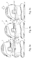
- FIGS. 3a-3c the vacuum cleaner is shown in different states.
- a further function of the bracket 25 according to the invention becomes clear, namely the function as a positioning element for the suction head 3.
- the suction head 3 is shown in a working or use position.
- the suction head 3 is fastened to the tank 2 in such a way that the plane H is oriented horizontally (or parallel to the support plane H ") .
- the bracket 25 is also aligned in this state in or parallel to the plane H.
- the plane H is present also parallel to the plane H ', which is determined by the upper edge of the container 20, 21 (see. FIG. 3a ).
- FIG. 3a the suction head 3 is detached from the tank 2 and shown lifted.
- the container 20, 21 facing away from edge 27 of the bracket 25 biases a plane K, which encloses the angle ⁇ with the plane H '.
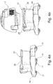
- the bracket can, for example, by a latching mechanism 28 (see also Fig. 4b ), which has a latching nose 28 '(see. Fig. 5 ), which rests on the upper edge of the container, stable in the position according to FIG. 3a be set.
- the latching mechanism comprises a projection and / or a recess which is formed on the bracket 25 and facing the container wall 20.
- the projection or the depression cooperates with a corresponding projection or a corresponding depression, which is formed in the upper region of the container wall 20.
- the projections / depressions act together so that only when a minimum force on the upper edge 27 of the bracket 25, the latching is released and the bracket can be pivoted to the basic position. By exerting this minimum force / torque, the detent is pushed over the edge of the container and locks in the working position (in which the edge 27 of the bracket 25 horizontally in level H '). The detent then engages below a fold of the container edge.
- the bracket 25 is held in the park position by one.
- bracket 25 is releasably fixed in a parking position in which moisture from the suction head 3 can flow quickly and completely into the tank 2.
- the suction head 3 on the bracket 25 (or the edge 27 of the bracket 25) are placed and the bracket 25 support the suction head 3.
- the plane H of the suction head 3 is no longer aligned horizontally or parallel to the plane H 'and to the ground H ", but is inclined relative to H' and H" by an angle ⁇ of approximately 6 °.
- the head 3 is thus stored obliquely.
- Water which is located in the interior of the housing 30, runs downwards through the inclined position and enters the interior 22 of the tank 2.
- the in the FIG. 3b shown position is referred to as parking position, since the vacuum cleaner is not ready for use in this arrangement of components.
- the in the Figure 3c shown position is referred to as a working or operational position, since the vacuum cleaner in this arrangement of components go into operation or may be in operation.
- the bracket 25 can be held in a position by static friction in the joints or bearings 26.
- FIGS. 4a and 4b the two positions of the bracket 25 are shown, namely the basic position with a plane defined by the edge 27 horizontal plane parallel to and flush with the upper edge of the container 20, 21 in FIG. 4a , and the parking position with a plane spanned by the edge 27, which is inclined to the horizontal H "and the upper edge H 'of the container 20, 21 and not flush with the upper edge, in FIG. 4b , H 'and K include an angle ⁇ , H' and H an angle ⁇ .
- the position of the bracket 25 in the parking position is in the FIG. 7 sketched schematically.
- the upper edge 27 of the yoke 25 extends beyond the plane defined by the container rim 20 '.
- the latching nose pushes 28 '(for example, by means of a chamfer of the support surface relative to the horizontal) to the outside (arrow a) and the bracket 25 can be pushed down into the working position.
Landscapes
- Engineering & Computer Science (AREA)
- Mechanical Engineering (AREA)
- Life Sciences & Earth Sciences (AREA)
- Biodiversity & Conservation Biology (AREA)
- Ecology (AREA)
- Forests & Forestry (AREA)
- Wood Science & Technology (AREA)
- Botany (AREA)
- Environmental Sciences (AREA)
- Nozzles For Electric Vacuum Cleaners (AREA)
- Filters For Electric Vacuum Cleaners (AREA)
Description
- Die Erfindung betrifft Staubsauger, umfassend: einen Flüssigkeitsbehälter; und einen Saugkopf, der in einer ersten Position relativ zum Flüssigkeitsbehälter abnehmbar am Flüssigkeitsbehälter angeordnet ist.
- Es ist eine Vielzahl von Staubsaugern zur Reinigung von Räumen bekannt. Dabei wird durch einen Motor ein Luftstrom erzeugt, der über eine Düse Staub und andere Verschmutzungen ansaugt. Der Luftstrom wird im Staubsauger gefiltert, d. h. die Staub- und Schmutzpartikel werden aus dem Luftstrom extrahiert und zur späteren Entsorgung in einem Filter gesammelt.
- Herkömmliche Staubsauger verwenden Filter aus Papier oder Kunstfasermaterialien. Bei diesen Systemen lässt jedoch die Saugkraft mit zunehmender Verschmutzung des Filters nach. Dies wirkt sich negativ auf die Reinigungskraft des Staubsaugers aus. Außerdem können angesaugte Partikel in die Umgebungsluft gelangen.
- Bei sogenannten Wasserstaubsaugern wird anstelle des Papierfilters ein Wasserbad eingesetzt. Das Wasser ist in einem Tank untergebracht, in den die angesaugte Luft strömt. In der Regel ist der Tank abnehmbar am Staubsaugergehäuse angebracht, sodass verschmutztes Wasser einfach ersetzt werden kann. Das Wasserbad nimmt die Staub- und Schmutzpartikel auf und bindet diese. Die gereinigte Luft strömt, meist über einen Separator, in den mit dem Wassertank verbundenen Saugkopf, in dem der Motor untergebracht ist, und wird anschließend an die Umgebung abgegeben. Da Staub und Schmutz vollständig im Wasser gebunden werden, ist die abgegebene Luft bestmöglich gereinigt. Gesundheitliche Beschwerden, die durch Staub, Schmutz Hausstaubmilben u. ä. ausgelöst werden, können so verhindert werden.
- Allerdings besteht bei Wasserstaubsaugern der Nachteil, dass stets mit Feuchtigkeit umgegangen werden muss, die sich an unerwünschten Stellen in den Bauteilen ansammelt. Ein Abtrocknen dieser Bauteile dauert in der Regel relativ lange.
- Aus der
US 6,055,700 A ist ein Vakuumgerät zur Aufnahme von nassen oder trockenen Stoffen mit einem Saugkopfverschluss mit Rastfunktion bekannt, welches den nächstliegenden Stand der Technik bildet. - Der Saugkopf des dort beschriebenen Vakuumgeräts ist in einer ersten Position relativ zum Sammelbehälter abnehmbar am Sammelbehälter angeordnet. Das Vakuumgerät weist ein Positionierelement auf, das so einstellbar ist, dass der Saugkopf in einer zweiten Position relativ zum Sammelbehälter anordenbar ist, wobei der Saugkopf in der zweiten Position relativ zur ersten Position um einen ersten Winkel größer als 0° geneigt ist. Die geneigte Position dient aber einzig der Installation und Verriegelung des Saugkopfes mit dem Deckel des Vakuumgeräts mittels des Positionierelements und stellt den ersten Schritte der Herstellung der Verbindung dar. Hierzu wird der Saugkopf zunächst auf dem Positionierelement aufgesetzt. Anschließend wird der Saugkopf nach unten abgesenkt, das Positionierelement nach außen gedrückt und verriegelt. Das Positionierelement dient somit der Arretierung des abnehmbaren Saugkopfes auf dem restlichen Staubsaugergehäuse.
- Die
US 2010/0139032 A1 beschreibt einen Nass-/ Trockenvakuumstaubsauger mit einem entfernbarem Aufnahmebehälter. - Es ist eine Aufgabe der vorliegenden Erfindung, einen Staubsauger mit Wasserbad bereitzustellen, bei dem der Umgang mit feuchten Bauteilen erleichtert wird.
- Diese Aufgabe wird gelöst durch einen Staubsauger gemäß dem Anspruch 1. Vorteilhafte Ausgestaltungen sind Gegenstand der abhängigen Ansprüche.
- Der erfindungsgemäße Staubsauger umfasst: einen Flüssigkeitsbehälter; und einen Saugkopf, der in einer ersten Position relativ zum Flüssigkeitsbehälter abnehmbar am Flüssigkeitsbehälter angeordnet ist, wobei der Staubsauger ein Positionierelement aufweist, das so einstellbar ist, dass der Saugkopf in einer zweiten Position relativ zum Flüssigkeitsbehälter anordenbar ist, wobei der Saugkopf in der zweiten Position relativ zur ersten Position um einen ersten Winkel (γ) größer als 0° geneigt ist.
- Der Saugkopf weist wenigstens ein Gehäuse und einen im Gehäuse angeordneten Saugmotor auf. Außerdem kann im Inneren des Gehäuses ein Separator vorgesehen sein. Die vom Saugmotor angesaugte Luft wird zunächst über einen Eintrittskanal in den Innenraum des Wasserbehälters geführt. Dort gibt die Luft Schmutz- und Staubpartikel ab, die im Wasserbad gebunden werden. Anschließend wird die Luft (evtl. über einen Separator) in den Saugkopf gesaugt und von dort aus an die Umgebung abgegeben.
- In der ersten Position (Arbeits- oder Einsatzposition) ist der Saugkopf am Behälter befestigt, z.B. mittels eines Rastmechanismus, in der zweiten Position (Parkposition) liegt der Saugkopf geneigt auf dem Behälter und dem Positionierelement auf. Die geneigte Position bzw. Schrägposition gegenüber der Horizontalen (bzw. gegenüber dem Auflageuntergrund und/oder gegenüber der von der Oberkante der Behälteröffnung aufgespannten Ebene) führt dazu, dass Wasser, das während des Betriebs des "Wasserstaubsaugers" in den Motorkopf gelangt ist, schräg nach unten hin abfließt und dann in den Behälter hinein abfließt bzw. abtropft. Der Saugkopf nimmt somit, wenn er abgenommen wird, eine definierte Park- oder Auflageposition gegenüber dem Behälter ein. Auf diese Weise wird das Trocknen des Saugkopfs beschleunigt und verbessert.
- Die Handhabung des Saugkopfs wird somit erleichtert, da dieser in feuchtem Zustand zum Trocknen nicht vom Behälter entfernt werden muss. Er wird lediglich geneigt auf den Behälter aufgelegt. Der Saugkopf, insbesondere die Bereiche um den Separator und das Gebläse des Saugmotors, können besser abtrocknen. Eine Ansammlung von Feuchtigkeit (mit negativen Folgen wie Schimmel oder Geruchsbildung) kann verhindert werden.
- Der erste Winkel (γ) liegt vorzugsweise zwischen 3° und 15°, insbesondere zwischen 3° und 10°. Bei diesen Winkeln wird eine zum Abtrocknen ausreichende Neigung erreicht, bei gleichzeitig stabiler Lage des Saugkopfs auf der Oberseite des Behälters.
- Das Positionierelement ist insbesondere als Bügel ausgebildet.
- Vorzugsweise ist das Positionierelement verschwenkbar am Flüssigkeitsbehälter angeordnet. Der Bügel wirkt damit wie der Handgriff des Behälters, vergleichbar dem Handgriff eines Eimers, und kann, neben seiner Funktion als Positionierelement, auch als Handgriff dienen.
- Das Positionierelement weist wenigstens eine erste Einstellposition auf, die der ersten Position des Saugkopfes entspricht, und eine zweite Einstellposition, die der zweiten Position des Saugkopfes entspricht. Die Entsprechung der Positionen bedeutet, dass in der ersten Einstellposition des Positionierelements der Saugkopf in seiner ersten Position (Einsatzposition) am Behälter angeordnet ist, in der zweiten Einstellposition des Positionierelements der Saugkopf in seiner zweiten Position (Parkposition) am Behälter angeordnet ist bzw. auf dem Behälter aufliegt.
- Das Positionierelement ist vorzugsweise in der ersten Einstellposition und/oder in der zweiten Einstellposition durch einen Arretiermechanismus, insbesondere durch einen Rastmechanismus, festlegbar. Der Mechanismus ist so ausgelegt, dass das Positionierelement unter dem Einfluss der Gewichtskraft des auf dem Positionierelement aufliegenden Saugkopfs seine Position beibehält. Lediglich, wenn zusätzliche Kraft von außen auf das Positionierelement einwirkt, kann die Arretierung/Verrastung gelöst und das Positionierelement in die erste Einstellposition gebracht werden. Dieses Entrasten kann beispielsweise durch Ausüben einer Kraft auf die Oberseite des Saugkopfs bewerkstelligt werden.
- Das Positionierelement kann eine dritte Einstellposition aufweisen, in der das Positionierelement als Handgriff zum Transport des Flüssigkeitsbehälters einsetzbar ist. Ein Verrasten oder anderes Festlegen in dieser dritten Einstellposition ist ebenfalls denkbar.
- Das Positionierelement weist insbesondere eine dem Saugkopf zugewandte Kante auf, die in der ersten Einstellposition parallel und/oder bündig zu einer Oberkante der eine obere Öffnung des Flüssigkeitsbehälters begrenzenden Wand angeordnet ist.
- In einer Ausführungsform der Erfindung weist das Positionierelement eine dem Saugkopf zugewandte Kante auf, die in der zweiten Einstellposition um einen zweiten Winkel (β) größer als 0° gegenüber einer Oberkante der eine obere Öffnung des Flüssigkeitsbehälters begrenzenden Wand geneigt ist.
- Die Oberkante ist in der bestimmungsgemäßen Einsatzposition des Behälters in der Regel parallel zum Untergrund ausgerichtet. Eine Neigung des Saugkopfs stellt somit eine Neigung des Saugkopfs gegenüber der Oberkante und dem Untergrund dar.
- Der zweite Winkel (β) liegt vorzugsweise zwischen 5° und 20°, insbesondere zwischen 6° und 15°. Es gibt einen funktionalen Zusammenhang zwischen dem ersten Winkel und dem zweiten Winkel.
- Der Saugkopf kann Mittel zur stabilen Ablage des Saugkopfes auf einer ebenen Fläche aufweisen. So kann der Saugkopf in einer stabilen Lage auf dem Boden abgelegt werden, wenn er vom Behälter entfernt wird. Die Position kann dabei so geneigt sein, dass die Unterseite des Gehäuses (schräg) nach oben weist, also kein Wasser aus dem Innenraum des Gehäuses abfließen kann. Eine "Zwischenlagerung" des Saugkopfs, beispielsweise zum Entleeren des Wasserbehälters, wird so ermöglicht, ohne die Umgebung durch abtropfendes (Schmutz-)Wasser zu verunreinigen.
- Der Saugkopf kann ein Trägerteil zur Auflage des Flüssigkeitsbehälters auf dem Trägerteil aufweisen. Das Trägerteil ist in der Regel wie ein verfahrbarer Untersatz ausgebildet.
- Das Trägerteil weist vorzugsweise eine Vertiefung auf, deren Querschnitt dem Querschnitt der Bodenfläche des Flüssigkeitsbehälters entspricht. So ist eine passgenaue Ablage des Behälters auf dem Trägerteil gewährleistet, ohne dass der Behälter gegenüber dem Trägerteil seitlich bewegt werden kann.
- Das Trägerteil kann Rollen zur bewegbaren Auflage des Trägerteils auf dem Untergrund aufweisen. Der Staubsauger ist somit insgesamt auf dem Untergrund verfahrbar.
- Die Erfindung betrifft im Ergebnis einen Staubsauger mit einem Trägerteil, einem Flüssigkeitstank und einem Saugkopf. Am Flüssigkeitstank ist ein Bügel verschwenkbar befestigt, sodass der Bügel als Positionierelement für den Saugkopf dienen kann. Der Saugkopf kann in einer Parkposition, die gegenüber der Oberkante des Tanks um einen Winkel γ größer als 0° geneigt ist, angeordnet werden, indem der Saugkopf auf dem Bügel aufliegt. Der Bügel ist in der Parkposition mit dem Behälter verrastet.
- Weitere Merkmale und Vorteile der Erfindung ergeben sich aus der Beschreibung eines bevorzugten Ausführungsbeispiels anhand der Figuren.
- Figur 1
- ist eine perspektivische Ansicht einer Ausführungsform eines Staubsaugers gemäß der vorliegenden Erfindung;
- Figur 2
- ist eine Seitenansicht der Ausführungsform aus der
Figur 1 ; - Figur 3a-3c
- zeigen Seitenansichten der Ausführungsform aus der
Figur 1 in verschiedenen Positionen; - Figur 4a, 4b
- zeigen Ansichten von Komponenten des Staubsaugers der Ausführungsform aus der
Figur 1 ; - Figur 5
- ist eine perspektivische Ansicht von Komponenten des Staubsaugers der Ausführungsform aus der
Figur 1 ; und - Figur 6
- ist eine weitere Seitenansicht der Ausführungsform aus der
Figur 1 . - Figur 7
- ist eine Detailansicht der Ausführungsform aus der
Figur 1 . - In der
Figur 1 ist eine perspektivische Ansicht der bevorzugten Ausführungsform des erfindungsgemäßen Staubsaugers dargestellt. - Der Staubsauger umfasst drei wesentliche Komponenten, nämlich ein Trägerteil 1, einen Flüssigkeits- bzw. Wassertank 2 und einen Saugkopf 3.
- Das Trägerteil 1 weist einen Grundkörper 10 und Rollen 11 auf, die ein komfortables Verfahren des Trägerteils 1 auf dem Boden erlauben. Im Grundkörper 10 ist eine Vertiefung 12 (vgl.
Figur 5 ) ausgebildet, in die der Tank 2 passgenau eingesetzt werden kann, sodass der Tank 2 gegenüber seitlichen Bewegungen gesichert ist. - Der Tank 2 weist, wie in der
Figur 5 dargestellt, eine Seitenwand 20 und eine Bodenwand 21 auf, die einen Innenraum 22 begrenzen. Der Innenraum 22 ist bei Verwendung des Staubsaugers wenigstens teilweise mit Wasser befüllt. Außerdem weist der Tank 2 ein Anschlusselement 23 zum Anschluss eines Schlauchs 4 (vgl.Figur 6 ) auf. Das Anschlusselement weist eine (in derFigur 5 abgedeckte) Öffnung auf, die in einen Kanal 24 mündet, der in den Innenraum 22 mündet. Durch den Schlauch 4 angesaugte Luft strömt demnach durch die Öffnung des Anschlusselements 23 über den Kanal 24 in den Innenraum 22 des Wassertanks 2. - Außerdem weist der Tank 2 einen Bügel 25 (vgl.
Figur 5 ) auf, der über beidseitig am Aufnahmebehälter (der Aufnahmebehälter besteht aus den Wänden 20 und 21) angeordnete Drehgelenke 26 relativ zum Behälter verschwenkbar ist. Der Bügel 25 kann, wie etwa in derFigur 5 dargestellt, um etwa 90° relativ zur Behälteroberkante nach oben verschwenkt und als Tragegriff verwendet werden. Der Tank 2 kann auf diese Weise einfach vom Trägerteil 1 abgehoben und zu einer Frischwasser-/Abwasserstation transportiert werden. - Der Saugkopf 3 ist passgenau und abnehmbar an der Oberseite des Wassertanks 2 befestigt. Der Saugkopf 3 weist ein Gehäuse 30 auf, in dem im Wesentlichen ein Separator und ein Saugmotor untergebracht sind. Über den Separator (nicht dargestellt) wird die gereinigte Luft vom Saugmotor (nicht dargestellt) aus dem Innenraum 22 des Wassertanks 2 angesaugt und anschließend an die Umgebung abgegeben.
- Der Saugkopf 3 weist außerdem ein Bedienfeld 31 mit Knöpfen 32 zum An-/Ausschalten oder zum Einstellen, z. B. der Saugkraft, des Staubsaugers auf.
- Es ist jedoch bei der Verwendung des Staubsaugers unvermeidlich, dass der Separator mit Wasser in Berührung kommt und Feuchtigkeit sogar bis in den Bereich des Saugmotors vordringt. Dies ist unerwünscht, da diese Bereiche dadurch leicht verschmutzen und sich Gerüche und Schimmel bilden können.
- Außerdem ist es unkomfortabel, mit feuchten Komponenten zu hantieren. Wird beispielsweise der Saugkopf 3 vom Tank 2 abgenommen (vgl.
Figur 2 ) und ist der Saugkopf 3 innen noch feucht, so können Wassertropfen insbesondere im Umgebungsbereich des Staubsaugers auf den Boden tropfen und den Boden (der unter Umständen gerade gereinigt wurde) verschmutzen. - Der abgenommene Saugkopf 3 wird, wie in der
Figur 2 rechts dargestellt, nach dem Abnehmen in einem Winkel α (zwischen der Horizontalen Ebene H und der vertikalen Ebene V) von ca. 33° abgelegt. Das Gehäuse 30 ist dabei so ausgebildet, dass der Saugkopf 3 in dieser Position stabil auf dem Boden abgelegt werden kann. Die Ebene H ist so definiert, dass die Ebene horizontal ausgerichtet ist, wenn der Saugkopf 3 in Arbeitsposition (vgl.Figur 1 ) am Tank 2 angeordnet und das Trägerteil 1 auf einer horizontalen Ebene bzw. einem horizontalen Untergrund abgestellt ist. - Der Saugkopf 3 kann im Übrigen durch einen Verschluss, z. B. durch einen lösbaren Schnappverschluss 33, abnehmbar am Tank 2 befestigt sein.
- In den
Figuren 3a-3c ist der Staubsauger in verschiedenen Zuständen dargestellt. Dabei wird eine weitere erfindungsgemäße Funktion des Bügels 25 deutlich, nämlich die Funktion als Positionierelement für den Saugkopf 3. - In der
Figur 3c ist der Saugkopf 3 in einer Arbeits- oder Einsatzposition dargestellt. Der Saugkopf 3 ist dabei so am Tank 2 befestigt, dass die Ebene H horizontal (bzw. parallel zur Auflageebene H") ausgerichtet ist. Auch der Bügel 25 ist in diesem Zustand in bzw. parallel zur Ebene H ausgerichtet. Die Ebene H ist dabei auch parallel zur Ebene H', die durch die Oberkante des Behälters 20, 21 bestimmt wird (vgl.Figur 3a ), ausgerichtet. - In der
Figur 3a ist der Saugkopf 3 vom Tank 2 gelöst und abgehoben dargestellt. Der Bügel 25, der in der Arbeitsposition des Saugkopfes 3 (vgl.Figur 1 ) parallel ausgerichtet war, ist nun um einen Winkel β von ca. 10° gegenüber der Ebene H' nach oben verschwenkt. Die dem Behälter 20, 21 abgewandte Kante 27 des Bügels 25 spannt eine Ebene K auf, die den Winkel β mit der Ebene H' einschließt. - Der Bügel kann beispielsweise durch einen Rastmechanismus 28 (vgl. auch
Fig. 4b ), der eine Rastnase 28' (vgl.Fig. 5 ) aufweist, die sich auf den oberen Rand des Behälters aufliegt, stabil in der Position gemäßFigur 3a festgelegt sein. Der Rastmechanismus umfasst einen Vorsprung und/oder eine Vertiefung auf, der/die am Bügel 25 ausgebildet ist und zur Behälterwand 20 weist. Der Vorsprung bzw. die Vertiefung wirkt mit einem entsprechenden Vorsprung bzw. einer entsprechenden Vertiefung, die im oberen Bereich der Behälterwand 20 ausgebildet ist, zusammen. Die Vorsprünge/Vertiefungen wirken so zusammen, dass erst bei Ausübung einer Mindestkraft auf die Oberkante 27 des Bügels 25 die Verrastung gelöst wird und der Bügel in die Grundposition geschwenkt werden kann. Durch Ausüben dieser Mindestkraft/dieses Mindestdrehmoments wird die Rastnase über den Rand des Behälters geschoben und rastet in der Arbeitsposition (in der die Kante 27 des Bügels 25 horizontal in der Ebene H' liegt) ein. Die Rastnase rastet dann unterhalb eines Falzes des Behälterrandes ein. - In dieser Ausführungsform wird der Bügel 25 in der Parkposition durch einen gehalten.
- Auf diese Weise wird der Bügel 25 lösbar in einer Parkposition fixiert, in der Feuchtigkeit aus dem Saugkopf 3 rasch und vollständig in den Tank 2 abfließen kann.
- In der Parkposition gemäß
Figur 3b kann der Saugkopf 3 auf den Bügel 25 (bzw. die Kante 27 des Bügels 25) aufgelegt werden und der Bügel 25 den Saugkopf 3 abstützen. Die Ebene H des Saugkopfes 3 ist dabei nicht mehr horizontal bzw. parallel zur Ebene H' und zum Untergrund H" ausgerichtet, sondern gegenüber H' und H" um einen Winkel γ von ca. 6° geneigt. Der Kopf 3 ist damit schräg abgelegt. Wasser, das sich im Inneren des Gehäuses 30 befindet, läuft durch die Schrägstellung nach unten hin ab und gelangt in den Innenraum 22 des Tanks 2. - Die in der
Figur 3b dargestellte Position wird als Parkstellung bezeichnet, da der Staubsauger in dieser Anordnung der Bauteile nicht einsatzbereit ist. Die in derFigur 3c dargestellte Position wird als Arbeits- oder Einsatzstellung bezeichnet, da der Staubsauger in dieser Anordnung der Bauteile in Betrieb gehen bzw. in Betrieb sein kann. - In einer anderen Ausführungsform der Erfindung kann der Bügel 25 durch Haftreibung in den Gelenken bzw. Lagern 26 in einer Position gehalten werden.
- In den
Figuren 4a und 4b sind die beiden Positionen des Bügels 25 dargestellt, nämlich die Grundposition mit einer durch die Kante 27 aufgespannten horizontalen Ebene parallel und bündig zur Oberkante des Behälters 20, 21 inFigur 4a , und die Parkposition mit einer durch die Kante 27 aufgespannten Ebene, die zur Horizontalen H" und zur Oberkante H' des Behälters 20, 21 geneigt und mit der Oberkante nicht bündig ist, inFigur 4b . H' und K schließen einen Winkel β ein, H' und H einen Winkel γ. - Die Stellung des Bügels 25 in der Parkposition ist in der
Figur 7 schematisch skizziert. Die Rastnase 28' liegt auf dem Behälterrand 20' auf und hält so den Bügel 25 gegenüber einer durch den Pfeil A symbolisierten Kraft-/Drehmomenteinwirkung (A ist in Richtung des Behälterbodens gerichtet) in der Position. Somit erstreckt sich die obere Kante 27 des Bügels 25 über die durch den Behälterrand 20' bestimmte Ebene hinaus. Erst bei Überschreiten eines bestimmten Werts A schiebt sich die Rastnase 28' (beispielsweise mittels einer Abschrägung der Auflagefläche gegenüber der Horizontalen) nach außen (Pfeil a) und der Bügel 25 lässt sich nach unten in die Arbeitsposition schieben. Es kann ein Anschlag 29 vorgesehen sein, der den Weg des Bügels nach unten begrenzt.
Claims (14)
- Staubsauger mit Wasserbad, umfassend:einen Flüssigkeitsbehälter (2), der zumindest teilweise mit Wasser befüllt ist, um Schmutz und Staub zu binden; undeinen Saugkopf (3), der in einer ersten Position relativ zum Flüssigkeitsbehälter (2) abnehmbar am Flüssigkeitsbehälter (2) angeordnet ist und der Staubsauger ein Positionierelement (25) aufweist, das so einstellbar ist, dass der Saugkopf (3) in einer zweiten Position relativ zum Flüssigkeitsbehälter (2) anordenbar ist, wobei der Saugkopf (3) in der zweiten Position relativ zur ersten Position um einen ersten Winkel (γ) größer als 0° geneigt ist und die geneigte zweite Position dem Abtropfen und Trocknen des Saugkopfes (3) dient.
- Staubsauger nach Anspruch 1,
dadurch gekennzeichnet, dass
der erste Winkel (γ) zwischen 3° und 15° liegt. - Staubsauger nach Anspruch 1 oder 2,
dadurch gekennzeichnet, dass
das Positionierelement (25) als Bügel ausgebildet ist. - Staubsauger nach einem der vorhergehenden Ansprüche,
dadurch gekennzeichnet, dass
das Positionierelement (25) verschwenkbar am Flüssigkeitsbehälter (2) angeordnet ist. - Staubsauger nach einem der vorhergehenden Ansprüche,
dadurch gekennzeichnet, dass
das Positionierelement (25) wenigstens eine erste Einstellposition aufweist, die der ersten Position des Saugkopfes (3) entspricht, und eine zweite Einstellposition, die der zweiten Position des Saugkopfes (3) entspricht. - Staubsauger nach einem der vorhergehenden Ansprüche,
dadurch gekennzeichnet, dass
das Positionierelement (25) in der ersten Einstellposition und/oder in der zweiten Einstellposition durch einen Arretiermechanismus, insbesondere einen Rastmechanismus festlegbar ist. - Staubsauger nach einem der vorhergehenden Ansprüche,
dadurch gekennzeichnet, dass
das Positionierelement (25) eine dritte Einstellposition aufweist, in der das Positionierelement (25) als Handgriff zum Transport des Flüssigkeitsbehälters (2) einsetzbar ist. - Staubsauger nach einem der vorhergehenden Ansprüche,
dadurch gekennzeichnet, dass
das Positionierelement (25) eine dem Saugkopf (3) zugewandte Kante aufweist, die in der ersten Einstellposition parallel und/oder bündig zu einer Oberkante der eine obere Öffnung des Flüssigkeitsbehälters (2) begrenzenden Wand (20) angeordnet ist. - Staubsauger nach einem der vorhergehenden Ansprüche,
dadurch gekennzeichnet, dass
das Positionierelement (25) eine dem Saugkopf (3) zugewandte Kante aufweist, die in der zweiten Einstellposition um einen zweiten Winkel (β) größer als 0° gegenüber einer Oberkante der eine obere Öffnung des Flüssigkeitsbehälters (2) begrenzenden Wand (20) geneigt ist. - Staubsauger nach Anspruch 9,
dadurch gekennzeichnet, dass
der zweite Winkel (β) zwischen 5° und 20° liegt. - Staubsauger nach einem der vorhergehenden Ansprüche,
dadurch gekennzeichnet, dass
der Saugkopf (3) Mittel zur stabilen Ablage des Saugkopfes (3) auf einer ebenen Fläche aufweist. - Staubsauger nach einem der vorhergehenden Ansprüche,
dadurch gekennzeichnet, dass
der Staubsauger ein Trägerteil (1) zur Auflage des Flüssigkeitsbehälters (2) auf dem Trägerteil (1) aufweist. - Staubsauger nach Anspruch 12,
dadurch gekennzeichnet, dass
das Trägerteil (1) eine Vertiefung aufweist, deren Querschnitt dem Querschnitt der Bodenfläche des Flüssigkeitsbehälters (2) entspricht. - Staubsauger nach Anspruch 12 oder 13,
dadurch gekennzeichnet, dass
das Trägerteil (1) Rollen (11) zur bewegbaren Auflage des Trägerteils (1) auf dem Untergrund aufweist.
Applications Claiming Priority (2)
| Application Number | Priority Date | Filing Date | Title |
|---|---|---|---|
| DE102012102180A DE102012102180A1 (de) | 2012-03-15 | 2012-03-15 | Raumreinigungssystem mit Wasserbad |
| PCT/EP2013/053836 WO2013135482A1 (de) | 2012-03-15 | 2013-02-26 | Staubsauger mit wasserbad |
Publications (2)
| Publication Number | Publication Date |
|---|---|
| EP2825083A1 EP2825083A1 (de) | 2015-01-21 |
| EP2825083B1 true EP2825083B1 (de) | 2016-10-12 |
Family
ID=47780052
Family Applications (1)
| Application Number | Title | Priority Date | Filing Date |
|---|---|---|---|
| EP13707152.8A Active EP2825083B1 (de) | 2012-03-15 | 2013-02-26 | Staubsauger mit wasserbad |
Country Status (8)
| Country | Link |
|---|---|
| US (1) | US9572464B2 (de) |
| EP (1) | EP2825083B1 (de) |
| CN (1) | CN104244790B (de) |
| DE (2) | DE102012102180A1 (de) |
| MX (1) | MX351525B (de) |
| PL (1) | PL2825083T3 (de) |
| SG (1) | SG11201405167XA (de) |
| WO (1) | WO2013135482A1 (de) |
Families Citing this family (11)
| Publication number | Priority date | Publication date | Assignee | Title |
|---|---|---|---|---|
| US10111562B2 (en) | 2015-09-30 | 2018-10-30 | Lowe's Companies, Inc. | Vacuum cleaner |
| USD802861S1 (en) * | 2015-12-18 | 2017-11-14 | Alfred Kaercher Gmbh & Co. Kg | Vacuum cleaners |
| USD804115S1 (en) * | 2016-06-17 | 2017-11-28 | Shop Vac Corporation | Vacuum cleaner |
| USD806332S1 (en) * | 2016-09-14 | 2017-12-26 | Shop Vac Corporation | Vacuum cleaner |
| WO2019125953A1 (en) | 2017-12-21 | 2019-06-27 | Tti (Macao Commercial Offshore) Limited | Support structure for a surface cleaning device |
| USD920607S1 (en) * | 2018-06-01 | 2021-05-25 | Techtronic Floor Care Technology Limited | Portable cleaner |
| USD876735S1 (en) * | 2018-07-04 | 2020-02-25 | Elektrowerkzeuge Gmbh Eibenstock | Vacuum cleaner |
| USD939794S1 (en) * | 2019-09-16 | 2021-12-28 | Techtronic Cordless Gp | Floor cleaner |
| AU2023425744A1 (en) | 2023-01-20 | 2025-07-31 | Sharkninja Operating Llc | Extraction cleaner |
| USD1039230S1 (en) * | 2023-04-20 | 2024-08-13 | Hongbo Luo | Vacuum cleaner |
| DE102024124227A1 (de) * | 2024-08-23 | 2026-02-26 | Festool Gmbh | Sauggerät mit Rastanordnung für Gehäuseoberteil und Gehäuseunterteil |
Family Cites Families (25)
| Publication number | Priority date | Publication date | Assignee | Title |
|---|---|---|---|---|
| CH474256A (de) | 1967-10-31 | 1969-06-30 | Manett S A | Wassersauger |
| US5086537A (en) * | 1990-12-04 | 1992-02-11 | Bissell, Inc. | Compact extractor |
| DE4206188C2 (de) * | 1992-02-28 | 1994-10-13 | Fedag Romanshorn Fa | Saugreinigungsgerät |
| JP3281683B2 (ja) | 1993-07-29 | 2002-05-13 | 三洋電機株式会社 | 電気掃除機 |
| US5611107A (en) * | 1994-10-31 | 1997-03-18 | Emerson Electric Co. | Latching mechanisms for wet/dry utility vacuum cleaner with detachable blower |
| US5954863A (en) * | 1996-11-18 | 1999-09-21 | Loveless; Michael L. | Wet and dry vacuum with float valve system |
| US6055700A (en) * | 1998-04-21 | 2000-05-02 | Emerson Electric Co. | Wet/dry vacuum with snap-action powerhead latch |
| US6158083A (en) * | 1998-08-31 | 2000-12-12 | Emerson Electric, Co. | Wet/dry vacuum with reduced operating noise |
| DE19926828A1 (de) | 1999-06-12 | 2000-12-14 | Kaercher Gmbh & Co Alfred | Staubsauger |
| US6249933B1 (en) | 1999-08-26 | 2001-06-26 | Shop Vac Corporation | Pump having sealless shaft |
| US6596044B1 (en) | 2000-03-06 | 2003-07-22 | The Hoover Company | Dirt collecting system for a vacuum cleaner |
| JP2002209812A (ja) | 2001-01-15 | 2002-07-30 | Sanyo Electric Co Ltd | 電気掃除機 |
| US6807706B2 (en) * | 2002-02-07 | 2004-10-26 | Koblenz Electrica, S.A. De C.V. | Vacuum cleaner locking system |
| CN2596927Y (zh) | 2003-01-16 | 2004-01-07 | 宁波富达电器有限公司 | 水过滤型真空吸尘器 |
| US7152274B2 (en) | 2003-04-17 | 2006-12-26 | The Hoover Company | Handle and latch for a removable dirt separation system |
| ITBS20030108A1 (it) | 2003-10-29 | 2005-04-30 | Matic Di Capitani Emilio Alfredo | Apparecchio aspirapolvere e/o aspiraliquidi. |
| EP1535563A3 (de) | 2003-11-26 | 2005-12-21 | South Asia International (H.K.) Ltd. | Staubsauger mit Flüssigkeitsfilter |
| MXPA06006543A (es) * | 2003-12-08 | 2006-08-23 | Shop Vac Corp | Aspiradora con bateria recargable. |
| US20050257340A1 (en) | 2004-05-19 | 2005-11-24 | One World Technologies Limited | Wet/dry vacuum |
| US8074321B2 (en) * | 2005-02-28 | 2011-12-13 | Shop Vac Corporation | Dual-tank vacuum cleaner |
| DE102005018288A1 (de) | 2005-04-18 | 2006-10-19 | PROAIR GmbH Gerätebau | Reinigungsvorrichtung, vorzugsweise Naßsauger |
| CN102743128B (zh) | 2007-10-23 | 2015-07-01 | 莱克电气股份有限公司 | 水过滤吸尘器 |
| MX336973B (es) * | 2008-03-28 | 2016-02-05 | Emerson Electric Co | Ensamble de filtro de facil acceso para un electrodomestico de aspirado para polvo/liquidos. |
| US8973196B2 (en) * | 2008-12-08 | 2015-03-10 | Emerson Electric Co. | Slide-out drum with filter for a wet/dry vacuum appliance |
| US20120311811A1 (en) * | 2011-06-09 | 2012-12-13 | Emerson Electric Co. | Wet/dry vacuum appliance, dust filtration attachment therefore, and methods of use |
-
2012
- 2012-03-15 DE DE102012102180A patent/DE102012102180A1/de not_active Ceased
- 2012-03-15 DE DE202012011402U patent/DE202012011402U1/de not_active Expired - Lifetime
-
2013
- 2013-02-26 US US14/385,462 patent/US9572464B2/en active Active
- 2013-02-26 PL PL13707152T patent/PL2825083T3/pl unknown
- 2013-02-26 CN CN201380014102.2A patent/CN104244790B/zh active Active
- 2013-02-26 WO PCT/EP2013/053836 patent/WO2013135482A1/de not_active Ceased
- 2013-02-26 MX MX2014010968A patent/MX351525B/es active IP Right Grant
- 2013-02-26 EP EP13707152.8A patent/EP2825083B1/de active Active
- 2013-02-26 SG SG11201405167XA patent/SG11201405167XA/en unknown
Also Published As
| Publication number | Publication date |
|---|---|
| HK1203337A1 (en) | 2015-10-30 |
| WO2013135482A1 (de) | 2013-09-19 |
| DE102012102180A1 (de) | 2013-10-02 |
| MX351525B (es) | 2017-10-18 |
| MX2014010968A (es) | 2014-10-17 |
| EP2825083A1 (de) | 2015-01-21 |
| SG11201405167XA (en) | 2014-10-30 |
| PL2825083T3 (pl) | 2017-03-31 |
| CN104244790A (zh) | 2014-12-24 |
| CN104244790B (zh) | 2016-11-09 |
| US9572464B2 (en) | 2017-02-21 |
| DE202012011402U1 (de) | 2013-01-15 |
| US20150067979A1 (en) | 2015-03-12 |
Similar Documents
| Publication | Publication Date | Title |
|---|---|---|
| WO2013135482A1 (de) | Staubsauger mit wasserbad | |
| DE10335186B4 (de) | Naß-Trocken-Kombinationsstaubsauger | |
| DE3725204A1 (de) | Nasssauger | |
| DE10303677A1 (de) | Staubsauger | |
| DE1951306A1 (de) | Elektrischer Staubsauger | |
| EP2845530B1 (de) | Tragbares Sauggerät für Flüssigkeiten oder Flüssigkeits-/Luftgemische | |
| DE112011100895T5 (de) | Beutelfreigabegriff für ein Bodenreinigungsgerät | |
| WO2016058901A1 (de) | Flächen-reinigungsmaschine mit befeuchtungseinrichtung | |
| DE60015237T2 (de) | Saugreinigungsgerät | |
| EP0956806B1 (de) | Sauggerät zum Ansaugen von Schmutz od.dgl. enthaltendem Sauggut | |
| DE3436064C2 (de) | Naß- und Trockensauger | |
| DE212024000137U1 (de) | Reinigungsvorrichtung | |
| DE20311505U1 (de) | Staubabsauggerät | |
| EP2978354B1 (de) | Sauger | |
| DE4209297C2 (de) | Behandlungseinrichtung für den Reinraumbereich | |
| CH686702A5 (de) | Vorrichtung zum Auffangen von Kaffeesatz aus einem Abwasserstrom einer Kaffeemaschine. | |
| DE60026397T2 (de) | Staubsauger mit Flüssigkeitsbad | |
| DE102015016336B4 (de) | Nasssauger | |
| EP4176789B1 (de) | Filtereinheit zum einbau in eine staubsaugvorrichtung sowie staubsaugvorrichtung mit filtereinheit | |
| DE3020571A1 (de) | Staubsauer, insbesondere haushaltsstaubsauger | |
| DE202025105807U1 (de) | Staubsaugervorrichtung | |
| EP2803915B1 (de) | Vorrichtung zur Klimatisierung von Räumen | |
| WO2014075719A1 (de) | Saugvorrichtung | |
| DE8710437U1 (de) | Naßsauger | |
| EP2777465A2 (de) | Bodenreinigungsmaschine mit Handsaugschlauch |
Legal Events
| Date | Code | Title | Description |
|---|---|---|---|
| PUAI | Public reference made under article 153(3) epc to a published international application that has entered the european phase |
Free format text: ORIGINAL CODE: 0009012 |
|
| 17P | Request for examination filed |
Effective date: 20140827 |
|
| AK | Designated contracting states |
Kind code of ref document: A1 Designated state(s): AL AT BE BG CH CY CZ DE DK EE ES FI FR GB GR HR HU IE IS IT LI LT LU LV MC MK MT NL NO PL PT RO RS SE SI SK SM TR |
|
| AX | Request for extension of the european patent |
Extension state: BA ME |
|
| DAX | Request for extension of the european patent (deleted) | ||
| GRAP | Despatch of communication of intention to grant a patent |
Free format text: ORIGINAL CODE: EPIDOSNIGR1 |
|
| INTG | Intention to grant announced |
Effective date: 20160524 |
|
| GRAS | Grant fee paid |
Free format text: ORIGINAL CODE: EPIDOSNIGR3 |
|
| GRAA | (expected) grant |
Free format text: ORIGINAL CODE: 0009210 |
|
| AK | Designated contracting states |
Kind code of ref document: B1 Designated state(s): AL AT BE BG CH CY CZ DE DK EE ES FI FR GB GR HR HU IE IS IT LI LT LU LV MC MK MT NL NO PL PT RO RS SE SI SK SM TR |
|
| REG | Reference to a national code |
Ref country code: GB Ref legal event code: FG4D Free format text: NOT ENGLISH |
|
| REG | Reference to a national code |
Ref country code: CH Ref legal event code: EP |
|
| REG | Reference to a national code |
Ref country code: AT Ref legal event code: REF Ref document number: 835676 Country of ref document: AT Kind code of ref document: T Effective date: 20161015 |
|
| REG | Reference to a national code |
Ref country code: IE Ref legal event code: FG4D Free format text: LANGUAGE OF EP DOCUMENT: GERMAN |
|
| REG | Reference to a national code |
Ref country code: DE Ref legal event code: R096 Ref document number: 502013004947 Country of ref document: DE |
|
| REG | Reference to a national code |
Ref country code: CH Ref legal event code: NV Representative=s name: LERMERRAIBLE PATENT- UND RECHTSANWALTS PARTGMB, CH |
|
| REG | Reference to a national code |
Ref country code: LT Ref legal event code: MG4D |
|
| REG | Reference to a national code |
Ref country code: NL Ref legal event code: MP Effective date: 20161012 |
|
| REG | Reference to a national code |
Ref country code: FR Ref legal event code: PLFP Year of fee payment: 5 |
|
| PG25 | Lapsed in a contracting state [announced via postgrant information from national office to epo] |
Ref country code: LV Free format text: LAPSE BECAUSE OF FAILURE TO SUBMIT A TRANSLATION OF THE DESCRIPTION OR TO PAY THE FEE WITHIN THE PRESCRIBED TIME-LIMIT Effective date: 20161012 |
|
| PG25 | Lapsed in a contracting state [announced via postgrant information from national office to epo] |
Ref country code: SE Free format text: LAPSE BECAUSE OF FAILURE TO SUBMIT A TRANSLATION OF THE DESCRIPTION OR TO PAY THE FEE WITHIN THE PRESCRIBED TIME-LIMIT Effective date: 20161012 Ref country code: GR Free format text: LAPSE BECAUSE OF FAILURE TO SUBMIT A TRANSLATION OF THE DESCRIPTION OR TO PAY THE FEE WITHIN THE PRESCRIBED TIME-LIMIT Effective date: 20170113 Ref country code: NO Free format text: LAPSE BECAUSE OF FAILURE TO SUBMIT A TRANSLATION OF THE DESCRIPTION OR TO PAY THE FEE WITHIN THE PRESCRIBED TIME-LIMIT Effective date: 20170112 Ref country code: LT Free format text: LAPSE BECAUSE OF FAILURE TO SUBMIT A TRANSLATION OF THE DESCRIPTION OR TO PAY THE FEE WITHIN THE PRESCRIBED TIME-LIMIT Effective date: 20161012 |
|
| PG25 | Lapsed in a contracting state [announced via postgrant information from national office to epo] |
Ref country code: RS Free format text: LAPSE BECAUSE OF FAILURE TO SUBMIT A TRANSLATION OF THE DESCRIPTION OR TO PAY THE FEE WITHIN THE PRESCRIBED TIME-LIMIT Effective date: 20161012 Ref country code: FI Free format text: LAPSE BECAUSE OF FAILURE TO SUBMIT A TRANSLATION OF THE DESCRIPTION OR TO PAY THE FEE WITHIN THE PRESCRIBED TIME-LIMIT Effective date: 20161012 Ref country code: HR Free format text: LAPSE BECAUSE OF FAILURE TO SUBMIT A TRANSLATION OF THE DESCRIPTION OR TO PAY THE FEE WITHIN THE PRESCRIBED TIME-LIMIT Effective date: 20161012 Ref country code: IS Free format text: LAPSE BECAUSE OF FAILURE TO SUBMIT A TRANSLATION OF THE DESCRIPTION OR TO PAY THE FEE WITHIN THE PRESCRIBED TIME-LIMIT Effective date: 20170212 Ref country code: PT Free format text: LAPSE BECAUSE OF FAILURE TO SUBMIT A TRANSLATION OF THE DESCRIPTION OR TO PAY THE FEE WITHIN THE PRESCRIBED TIME-LIMIT Effective date: 20170213 Ref country code: NL Free format text: LAPSE BECAUSE OF FAILURE TO SUBMIT A TRANSLATION OF THE DESCRIPTION OR TO PAY THE FEE WITHIN THE PRESCRIBED TIME-LIMIT Effective date: 20161012 Ref country code: ES Free format text: LAPSE BECAUSE OF FAILURE TO SUBMIT A TRANSLATION OF THE DESCRIPTION OR TO PAY THE FEE WITHIN THE PRESCRIBED TIME-LIMIT Effective date: 20161012 |
|
| REG | Reference to a national code |
Ref country code: SK Ref legal event code: T3 Ref document number: E 22963 Country of ref document: SK |
|
| REG | Reference to a national code |
Ref country code: DE Ref legal event code: R097 Ref document number: 502013004947 Country of ref document: DE |
|
| PG25 | Lapsed in a contracting state [announced via postgrant information from national office to epo] |
Ref country code: CZ Free format text: LAPSE BECAUSE OF FAILURE TO SUBMIT A TRANSLATION OF THE DESCRIPTION OR TO PAY THE FEE WITHIN THE PRESCRIBED TIME-LIMIT Effective date: 20161012 Ref country code: EE Free format text: LAPSE BECAUSE OF FAILURE TO SUBMIT A TRANSLATION OF THE DESCRIPTION OR TO PAY THE FEE WITHIN THE PRESCRIBED TIME-LIMIT Effective date: 20161012 Ref country code: DK Free format text: LAPSE BECAUSE OF FAILURE TO SUBMIT A TRANSLATION OF THE DESCRIPTION OR TO PAY THE FEE WITHIN THE PRESCRIBED TIME-LIMIT Effective date: 20161012 Ref country code: RO Free format text: LAPSE BECAUSE OF FAILURE TO SUBMIT A TRANSLATION OF THE DESCRIPTION OR TO PAY THE FEE WITHIN THE PRESCRIBED TIME-LIMIT Effective date: 20161012 |
|
| PLBE | No opposition filed within time limit |
Free format text: ORIGINAL CODE: 0009261 |
|
| STAA | Information on the status of an ep patent application or granted ep patent |
Free format text: STATUS: NO OPPOSITION FILED WITHIN TIME LIMIT |
|
| PG25 | Lapsed in a contracting state [announced via postgrant information from national office to epo] |
Ref country code: BG Free format text: LAPSE BECAUSE OF FAILURE TO SUBMIT A TRANSLATION OF THE DESCRIPTION OR TO PAY THE FEE WITHIN THE PRESCRIBED TIME-LIMIT Effective date: 20170112 Ref country code: SM Free format text: LAPSE BECAUSE OF FAILURE TO SUBMIT A TRANSLATION OF THE DESCRIPTION OR TO PAY THE FEE WITHIN THE PRESCRIBED TIME-LIMIT Effective date: 20161012 |
|
| 26N | No opposition filed |
Effective date: 20170713 |
|
| PG25 | Lapsed in a contracting state [announced via postgrant information from national office to epo] |
Ref country code: MC Free format text: LAPSE BECAUSE OF FAILURE TO SUBMIT A TRANSLATION OF THE DESCRIPTION OR TO PAY THE FEE WITHIN THE PRESCRIBED TIME-LIMIT Effective date: 20161012 |
|
| REG | Reference to a national code |
Ref country code: CH Ref legal event code: PCAR Free format text: NEW ADDRESS: C/O MAIL BOXES ETC. FELDBERGSTRASSE 67, 4057 BASEL (CH) |
|
| REG | Reference to a national code |
Ref country code: IE Ref legal event code: MM4A |
|
| PG25 | Lapsed in a contracting state [announced via postgrant information from national office to epo] |
Ref country code: SI Free format text: LAPSE BECAUSE OF FAILURE TO SUBMIT A TRANSLATION OF THE DESCRIPTION OR TO PAY THE FEE WITHIN THE PRESCRIBED TIME-LIMIT Effective date: 20161012 |
|
| PG25 | Lapsed in a contracting state [announced via postgrant information from national office to epo] |
Ref country code: LU Free format text: LAPSE BECAUSE OF NON-PAYMENT OF DUE FEES Effective date: 20170226 |
|
| REG | Reference to a national code |
Ref country code: FR Ref legal event code: PLFP Year of fee payment: 6 |
|
| PG25 | Lapsed in a contracting state [announced via postgrant information from national office to epo] |
Ref country code: IE Free format text: LAPSE BECAUSE OF NON-PAYMENT OF DUE FEES Effective date: 20170226 |
|
| PG25 | Lapsed in a contracting state [announced via postgrant information from national office to epo] |
Ref country code: MT Free format text: LAPSE BECAUSE OF FAILURE TO SUBMIT A TRANSLATION OF THE DESCRIPTION OR TO PAY THE FEE WITHIN THE PRESCRIBED TIME-LIMIT Effective date: 20161012 |
|
| PG25 | Lapsed in a contracting state [announced via postgrant information from national office to epo] |
Ref country code: HU Free format text: LAPSE BECAUSE OF FAILURE TO SUBMIT A TRANSLATION OF THE DESCRIPTION OR TO PAY THE FEE WITHIN THE PRESCRIBED TIME-LIMIT; INVALID AB INITIO Effective date: 20130226 |
|
| REG | Reference to a national code |
Ref country code: CH Ref legal event code: PCAR Free format text: NEW ADDRESS: HERISAUERSTRASSE 81, 9200 GOSSAU SG (CH) |
|
| PG25 | Lapsed in a contracting state [announced via postgrant information from national office to epo] |
Ref country code: CY Free format text: LAPSE BECAUSE OF FAILURE TO SUBMIT A TRANSLATION OF THE DESCRIPTION OR TO PAY THE FEE WITHIN THE PRESCRIBED TIME-LIMIT Effective date: 20161012 |
|
| PG25 | Lapsed in a contracting state [announced via postgrant information from national office to epo] |
Ref country code: MK Free format text: LAPSE BECAUSE OF FAILURE TO SUBMIT A TRANSLATION OF THE DESCRIPTION OR TO PAY THE FEE WITHIN THE PRESCRIBED TIME-LIMIT Effective date: 20161012 |
|
| PG25 | Lapsed in a contracting state [announced via postgrant information from national office to epo] |
Ref country code: TR Free format text: LAPSE BECAUSE OF FAILURE TO SUBMIT A TRANSLATION OF THE DESCRIPTION OR TO PAY THE FEE WITHIN THE PRESCRIBED TIME-LIMIT Effective date: 20161012 |
|
| PG25 | Lapsed in a contracting state [announced via postgrant information from national office to epo] |
Ref country code: AL Free format text: LAPSE BECAUSE OF FAILURE TO SUBMIT A TRANSLATION OF THE DESCRIPTION OR TO PAY THE FEE WITHIN THE PRESCRIBED TIME-LIMIT Effective date: 20161012 |
|
| REG | Reference to a national code |
Ref country code: CH Ref legal event code: U11 Free format text: ST27 STATUS EVENT CODE: U-0-0-U10-U11 (AS PROVIDED BY THE NATIONAL OFFICE) Effective date: 20260301 |
|
| PGFP | Annual fee paid to national office [announced via postgrant information from national office to epo] |
Ref country code: GB Payment date: 20260219 Year of fee payment: 14 |
|
| PGFP | Annual fee paid to national office [announced via postgrant information from national office to epo] |
Ref country code: DE Payment date: 20260217 Year of fee payment: 14 |
|
| PGFP | Annual fee paid to national office [announced via postgrant information from national office to epo] |
Ref country code: AT Payment date: 20260216 Year of fee payment: 14 |
|
| PGFP | Annual fee paid to national office [announced via postgrant information from national office to epo] |
Ref country code: BE Payment date: 20260218 Year of fee payment: 14 Ref country code: IT Payment date: 20260227 Year of fee payment: 14 |
|
| PGFP | Annual fee paid to national office [announced via postgrant information from national office to epo] |
Ref country code: FR Payment date: 20260223 Year of fee payment: 14 |
|
| PGFP | Annual fee paid to national office [announced via postgrant information from national office to epo] |
Ref country code: CH Payment date: 20260301 Year of fee payment: 14 |
|
| PGFP | Annual fee paid to national office [announced via postgrant information from national office to epo] |
Ref country code: PL Payment date: 20260220 Year of fee payment: 14 |
|
| PGFP | Annual fee paid to national office [announced via postgrant information from national office to epo] |
Ref country code: SK Payment date: 20260219 Year of fee payment: 14 |