EP2824345B1 - Drehbarer Spannmechanismus - Google Patents
Drehbarer Spannmechanismus Download PDFInfo
- Publication number
- EP2824345B1 EP2824345B1 EP14174695.8A EP14174695A EP2824345B1 EP 2824345 B1 EP2824345 B1 EP 2824345B1 EP 14174695 A EP14174695 A EP 14174695A EP 2824345 B1 EP2824345 B1 EP 2824345B1
- Authority
- EP
- European Patent Office
- Prior art keywords
- engagement
- biasing
- engagement members
- members
- clamping mechanism
- Prior art date
- Legal status (The legal status is an assumption and is not a legal conclusion. Google has not performed a legal analysis and makes no representation as to the accuracy of the status listed.)
- Not-in-force
Links
- 230000007246 mechanism Effects 0.000 title claims description 70
- 238000012360 testing method Methods 0.000 claims description 35
- 238000002485 combustion reaction Methods 0.000 claims description 12
- 230000005540 biological transmission Effects 0.000 claims description 6
- 230000008878 coupling Effects 0.000 description 8
- 238000010168 coupling process Methods 0.000 description 8
- 238000005859 coupling reaction Methods 0.000 description 8
- 230000008602 contraction Effects 0.000 description 7
- 238000010276 construction Methods 0.000 description 5
- 230000005484 gravity Effects 0.000 description 5
- 230000002411 adverse Effects 0.000 description 2
- 230000008859 change Effects 0.000 description 2
- 238000010586 diagram Methods 0.000 description 2
- 239000000446 fuel Substances 0.000 description 2
- 238000005259 measurement Methods 0.000 description 2
- 241000282472 Canis lupus familiaris Species 0.000 description 1
- 230000009471 action Effects 0.000 description 1
- 238000013459 approach Methods 0.000 description 1
- 230000006835 compression Effects 0.000 description 1
- 238000007906 compression Methods 0.000 description 1
- 230000010485 coping Effects 0.000 description 1
- 230000000694 effects Effects 0.000 description 1
- 238000012423 maintenance Methods 0.000 description 1
- 238000011056 performance test Methods 0.000 description 1
- 230000009467 reduction Effects 0.000 description 1
Images


Classifications
-
- F—MECHANICAL ENGINEERING; LIGHTING; HEATING; WEAPONS; BLASTING
- F16—ENGINEERING ELEMENTS AND UNITS; GENERAL MEASURES FOR PRODUCING AND MAINTAINING EFFECTIVE FUNCTIONING OF MACHINES OR INSTALLATIONS; THERMAL INSULATION IN GENERAL
- F16D—COUPLINGS FOR TRANSMITTING ROTATION; CLUTCHES; BRAKES
- F16D11/00—Clutches in which the members have interengaging parts
- F16D11/08—Clutches in which the members have interengaging parts actuated by moving a non-rotating part axially
- F16D11/12—Clutches in which the members have interengaging parts actuated by moving a non-rotating part axially with clutching members movable otherwise than only axially
-
- F—MECHANICAL ENGINEERING; LIGHTING; HEATING; WEAPONS; BLASTING
- F16—ENGINEERING ELEMENTS AND UNITS; GENERAL MEASURES FOR PRODUCING AND MAINTAINING EFFECTIVE FUNCTIONING OF MACHINES OR INSTALLATIONS; THERMAL INSULATION IN GENERAL
- F16D—COUPLINGS FOR TRANSMITTING ROTATION; CLUTCHES; BRAKES
- F16D11/00—Clutches in which the members have interengaging parts
- F16D11/16—Clutches in which the members have interengaging parts with clutching members movable otherwise than only axially
-
- G—PHYSICS
- G01—MEASURING; TESTING
- G01M—TESTING STATIC OR DYNAMIC BALANCE OF MACHINES OR STRUCTURES; TESTING OF STRUCTURES OR APPARATUS, NOT OTHERWISE PROVIDED FOR
- G01M15/00—Testing of engines
- G01M15/02—Details or accessories of testing apparatus
-
- G—PHYSICS
- G01—MEASURING; TESTING
- G01M—TESTING STATIC OR DYNAMIC BALANCE OF MACHINES OR STRUCTURES; TESTING OF STRUCTURES OR APPARATUS, NOT OTHERWISE PROVIDED FOR
- G01M15/00—Testing of engines
- G01M15/04—Testing internal-combustion engines
Definitions
- the present invention relates to a rotation clamping mechanism (connecting mechanism) that transmits rotational power from a rotational driving apparatus to a rotated object, and in particular to a rotation clamping mechanism installed on a rotational driving apparatus.
- a rotational shaft coupling apparatus (see Japanese Laid-Open Patent Publication No. H05-113388 ) is one example of a rotational driving apparatus that clamps a rotated object and transmits rotational power. Such coupling apparatus is used in a cold test apparatus for a completed engine (internal combustion engine).
- a cold test apparatus uses a coupling apparatus to connect a motor of the test apparatus to a gear (for example, the drive plate) of a rotational shaft of the engine to be tested, and forcibly drives the engine using a motor to carry out various performance tests on the engine.
- the coupling apparatus described above is equipped with a meshing portion 13 that meshes with the gear of a rotational shaft, and is a construction where unbalanced weights 18c are provided on meshing hook portions 18 provided on the meshing portion 13 (see FIG. 1 of Patent Document 1).
- the meshing hook portions 18 are positioned so as to mesh with the gear of the rotational shaft of the engine and then the motor is driven to rotate the meshing portion 13.
- the meshing hook portions 18 of the meshing portion 13 and the unbalanced weights 18c rotate, and due to the centrifugal force of the unbalanced weights 18c, the meshing hook portions 18 are pressed against the gear so that the rotational shaft of the engine is clamped on the meshing portion 13.
- the rotational shaft of the engine starts rotating state, which makes testing possible.
- GB 399 907 A relates to a coupling for connecting together the printing-unit drive and the auxiliary web-feeding and other drives in printing machines operating from a reel.
- US-3,760,919 relates to a clutch operable by a control force and having as its driver a hub with opposed lugs and as its driven member a block mounting opposed pivoted dogs urged by springs into position to engage the opposed lugs of the driver.
- US-3,224,701 relates to a mechanism for supporting a hollow core, such as the core of a role of newsprint, at its ends in a suitable mechanism, such as a printing press.
- the present invention was conceived in view of the problems described above and aims to provide a rotation clamping mechanism constructed so as to be capable of suppressing the occurrence of vibration at the rotational driving apparatus more reliably, regardless of the state in which the rotational driving apparatus and the rotated object are connected.
- a rotation clamping mechanism including: a rotating member installed so as to be capable of being rotationally driven; and engagement members that are attached to the rotating member and transmits rotational power, wherein the engagement members are placed in engagement with a rotated object placed at a power transmission implementation position, which is in a predetermined positional relationship with the engagement members, and the rotated object is rotated by rotating the rotating member, at least two engagement members are attached to the rotating member, the engagement members are supported on the rotating member in state where the engagement members are capable of swinging to an engagement position where there is engagement whereby it is possible to transmit power to the rotated object and to a release position where the engagement is released, the rotation clamping mechanism further includes: an opening/closing mechanism that opens and closes the engagement members between the engagement position and the release position; and a biasing member that biases the engagement members toward the engagement position, and when positioned at the engagement position, the plurality of engagement members clamp the rotated object in a floating state where the engagement members are pressed onto the rotated object by the
- a biasing direction of the biasing member is a direction perpendicular to an axial direction of a rotational axis of the rotating member, and a swinging plane of each engagement member may be a plane formed by a biasing direction of the biasing force applied to the engagement member and the axial direction of the rotational axis
- the opening/closing mechanism may include a pressing member that slidably contacts a sliding surface of the engagement member, the pressing member may apply a pressing force that resists the biasing force of the biasing member to the engagement members and may be capable of moving between a pressing position that positions the engagement members at the release position and a withdrawal position where the pressing member is separated from the engagement members, and the engagement members positioned at the engagement position may be pressed onto the rotated object in a floating state by the biasing force of the biasing member.
- a swinging axis position of each engagement member may be a midway position between a contact position of the engagement member on the rotated object and a contact position of the biasing member on the engagement member, and may be disposed so as to be offset toward the contact position between the biasing member and the engagement member from a midway position that is equidistant from both contact positions.
- the biasing member may be disposed so that the contact position with each engagement member in the biasing direction is positioned closer to the rotational axis than the swinging axis position of the biasing member.
- Another aspect of the present invention is a rotation test apparatus for an internal combustion engine including the rotation clamping mechanism described above, wherein the rotated object to be engaged and rotated by the engagement members is a drive plate of an internal combustion engine.
- the rotation clamping mechanism since a rotated object is clamped by a plurality of engagement members that are in a floating state, when the rotated object is rotated, the generation of vibration at the rotation clamping mechanism is suppressed more reliably. That is, even if the contact positions between the engagement members and the rotated object fluctuate when the rotated object is rotated, such fluctuations can be flexibly handled by the rotated object swinging with respect to the rotating member, which means that the shaking at the contact positions between the engagement members and the rotated object is prevented.
- a rotation clamping mechanism 1 (see FIG. 1 ) according to the present embodiment is used by a cold test apparatus for an engine (i.e., a testing apparatus for internal combustion engines).
- the cold test apparatus includes an engine loading portion (not shown) that is installed on an apparatus base portion, also not shown, and the rotation clamping mechanism 1, and is an apparatus for carrying out various tests on an engine by rotating a drive plate B (rotated object) of the engine, which has been loaded at a predetermined test position (power transmission implementation position) on the engine loading portion, using the rotation clamping mechanism 1.
- the rotation clamping mechanism 1 clamps the drive plate B of the engine placed at the test position and, as shown in FIG. 1 , is equipped with a rotating member 20 which is fixed to an output shaft portion 11 of a motor installed on the apparatus base portion. Accordingly, when the motor is driven, the output shaft portion 11 rotates around a rotational axis 11a so that the rotating member 20 integrally rotates together with the output shaft portion 11.
- the rotating member 20 is equipped with a front end portion 21 fixed to a front end of the output shaft portion 11, a base portion 22 fixed to a base end of the output shaft portion 11, and a sliding portion 23 that is cylindrically shaped and disposed so as to surround the base end of the base portion 22.
- a slider body 51, described later, that is capable of sliding along an outer circumference of the sliding portion 23 is disposed on the outside of the sliding portion 23.
- the front end portion 21, the base portion 22, and the sliding portion 23 are integrally assembled using fixing members such as screws 20a to construct the rotating member 20.
- the rotation clamping mechanism 1 includes engagement members 30 equipped with hook portions (contact portion) 31 that contact the drive plate B that is to be clamped, biasing members 40 that apply biasing forces to the engagement members 30, and cam rollers (pressing members) 52 for opening and closing the engagement members 30.
- each engagement member 30 includes: an arm portion 32 that is supported, at a swinging shaft portion 30a thereof, on the front end portion 21 of the rotating member 20 so as to be capable of swinging and extends from the swinging shaft portion 30a toward the front Xa in a rotational axis direction X; and a tail portion 33 that extends toward the rear Xb from the swinging shaft portion 30a.
- the arm portion 32 is equipped, at a front end thereof, with a hook portion 31 that contacts the drive plate B.
- the hook portion 31 is formed at a position where the drive plate B is contacted and is provided with a convex and convex form that is capable of engaging a gear G formed on the outer circumference of the drive plate B.
- the tail portion 33 includes a biasing surface 33a contacted by a head portion 42 of a biasing member 40, described later, a cam surface (pressing surface) 33b contacted by a cam roller 52, and a cam groove 34 formed so that a front Xa side in the rotational axis direction thereof is downwardly inclined toward the rotational axis 11a.
- the biasing surface 33a of the tail portion 33 is a surface that is inclined toward the rotational axis at the center of the rotating member 20 (i.e., toward the inside in the radial direction).
- the cam surface 33b is a surface positioned on the head portion 42 side of the cam groove 34 which the cam roller 52 can be pressed out of, and is an inclined surface that is inclined so as to approach the rotational axis 11a from the rear Xb side in the rotational axis direction toward the front Xa side. Note that the cam surface 33b does not need to be a groove surface inside a groove portion and may be an outer circumferential surface of the tail portion 33.
- the position (swinging axis position) of the swinging shaft portion 30a of each engagement member 30 is disposed at a midway position between the position of the hook portion 31 (the “contact position") and a position where the head portion 42 of the corresponding biasing member 40 contacts the engagement member 30 (the “biasing position”).
- the swinging axis position is disposed at a midway position between the position of the hook portion 31 and the position where the cam roller 52 contacts the engagement member 30.
- Each engagement member 30 is capable of swinging between an engagement position, which is a state where the hook portion 31 contacts the drive plate B (see FIG. 2 ), and a release position (see FIG. 1 ), which is a state where the engagement is released.
- Each engagement member 30 at the engagement position is in a state where the hook portion 31 engages the gear G of the drive plate B and the drive plate B is clamped by the rotation clamping mechanism 1 (see FIG. 2 ). If the rotating member 20 is rotated in a state where the drive plate B is clamped, the rotational power of the rotating member 20 will be transmitted via the engagement members 30 to the drive plate B, which makes it possible to rotate the drive plate B. That is, it is possible to drive (i.e., cold test) the engine without supplying fuel to the engine and actually burning the fuel.
- each engagement member 30 at the release position is in a state where the hook portion 31 is separated from the drive plate B. In this state, it is possible to load and unload the engine to be cold tested at a predetermined test position.
- the rotation clamping mechanism 1 is equipped with three engagement members 30, for example.
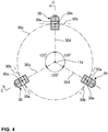
- the swinging axes 30b of the swinging shaft portions 30a of the respective engagement members 30 are tangents on a same inscribed circle 30c that is centered on the rotational axis 11a of the rotating member 20.
- the trajectories (swinging planes) 30d traced by center planes in the width direction of the engagement members 30 are all perpendicular to the circumferential direction of the inscribed circle 30c, and pass tangent points between the swinging axes 30b and the inscribed circle 30c.
- the three swinging planes 30d intersect at the position of the rotational axis 11a.
- the three engagement members 30 are disposed at equal intervals so that the three swinging planes 30d are disposed at 120° intervals. Note that although an example where the number of the engagement members 30 is three is given in the present embodiment, the number may be two or four or more.
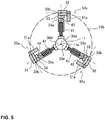
- the biasing members 40 applies a biasing force to the engagement members 30 so as to bias the engagement members 30 in a direction so as to rotate toward the engagement position, and as shown in FIG. 5 , one biasing member 40 is provided corresponding to each engagement member 30.
- each biasing member 40 is disposed between the rotational axis 11a and the tail portion 33 of an engagement member 30, and is equipped with a coil spring 41 and a head portion 42 attached to a front end portion of the spring 41.
- the spring 41 is a compression spring whose direction of extension/contraction is oriented in a radial direction perpendicular to the axial direction X of the rotational axis 11a of the rotating member 20 (a radial direction that extends toward the outside from the rotational axis 11a) and is in a state where the spring 41 is capable of extension.
- Each spring 41 is disposed so that the axis of extension/contraction that passes through the center of the spring 41 and extends in the direction of extension/contraction is positioned on the swinging plane 30d of the corresponding engagement member 30.
- the swinging plane 30d of each engagement member 30 matches a plane formed by the rotational axis 11a of the rotating member 20 and the axis of extension/contraction of the spring 41 (the biasing direction of the biasing member). In this way, in the same way as the swinging planes 30d of the engagement members 30, the springs 41 are disposed at 120° intervals.
- each spring 41 contacts the rotating member 20 at a base end portion thereof (an end portion on the rotational axis side in the radial direction), contacts the head portion at the front end portion on the outside in the radial direction (see FIG. 1 ), and biases the head portion 42 toward the outside in the radial direction in keeping with extension of the spring 41.
- the head portion 42 is a cylindrical body that is provided so as to cover the front end portion of the spring 41 that moves forward and backward and is attached to the spring 41.
- the head portion 42 also contacts the tail portion 33 of the engagement member 30 and a part of the head portion 42 that contacts the tail portion 33 is formed of a spherical portion.
- each engagement member 30 at the release position (see FIG. 1 ) is in a state where the tail portion 33 is pressed onto the cam roller 52 by the biasing force.
- the engagement member 30 in such state is positioned at the release position in a state where the engagement member 30 is sandwiched between the biasing member 40 and the cam roller 52.
- the engagement member 30 (see FIG. 2 ) at the engagement position is in a state where the hook portion 31 is pressed against the drive plate B by the biasing force.
- the biasing force of the biasing member 40 acts as a force that keeps the hook portion 31 in the engagement state with the drive plate B.
- Maintenance, such as replacement and removal, of the biasing members 40 according to the present embodiment is also simple. That is, in a state where an engine is not loaded at the test position, by merely removing the swinging shaft portions 30a of the engagement members 30 and removing the engagement members 30 from the rotating member 20, it is possible to easily remove the biasing members 40 to the outside in the radial direction.
- the distance D1 (see FIG. 2 ) from the swinging axis 30b to the contact position of the head portion 42 is shorter than the distance D2 from the swinging axis 30b to the hook portion 31. That is, the swinging shaft portion 30a is disposed so as to be offset from a midway position between the position of the hook portion 31 and the biasing position (i.e., the position where the head portion 42 contacts the engagement member 30) toward such biasing position.
- the slider 50 includes a slider body 51 that is cylindrical and is attached to the outer circumference of the rotating member 20 and the cam rollers (pressing members) 52 installed on rib portions 51a on the front side (in the rotational axis direction) of the slider body 51.
- the rib portions 51a are provided so as to protrude outward in the radial direction from the slider body 51 and rotatably support the cam rollers 52.
- the slider body 51 is disposed in a state so as to be slidable in the rotational axis direction X of the rotating member 20 and is moved forward and backward in the rotational axis direction X by an actuator (not shown).
- the cam rollers 52 are members that construct opening/closing mechanisms for the engagement members 30, with one cam roller 52 being provided corresponding to each engagement member 30.
- Each cam roller 52 moves forward and backward in the rotational axis direction X together with the slider body 51 when the slider body 51 is moved forward and backward, and is capable of moving forward and backward between a withdrawal position (see FIG. 2 ) when the cam rollers 52 have moved to the front Xa in the rotational axis direction X and a pressing position (see FIG. 1 ) when the cam rollers 52 have moved to the rear Xb.
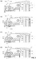
- Each cam roller 52 is a cylindrical member and the direction of the center axis (the center axis of the cylinder) 52a of each cam roller 52 matches the direction of the swinging axis 30b of the corresponding engagement member 30 (see FIGS. 3A to 3D , 4 , and 5 ).
- the center axes 52a of the three cam rollers 52 are positioned on tangents of a same inscribed circle 52b that is centered on the rotational axis 11a of the rotating member 20.
- Each cam roller 52 contacts the cam surface 33b of the tail portion 33 of the corresponding engagement member 30 in a slidable state and is disposed inside the cam groove 34. Note that the respective cam rollers 52 are disposed so that the center axes 52a thereof are positioned closer to the rotational axis that the position of the swinging axes 30b (see FIG. 1 ), and are disposed in a state that is perpendicular to the swinging planes 30d of the corresponding engagement members 30 (see FIG. 5 ).
- each cam surface 33b is inclined so as to become increasingly close to the rotational axis 11a toward the front in the direction in which the cam rollers 52 move forward and backward (i.e., the rotational axis direction).
- the tail portion 33 of the engagement member 30 is biased toward the outside in the radial direction (i.e., toward the engagement position) by the biasing member 40.
- the engagement members 30 are positioned in a state where the engagement members 30 are sandwiched by the cam rollers 52 and the biasing members 40 until the engagement members 30 reach the engagement position where the hook portions 31 engage the drive plate B.
- the state where the engagement members 30 are sandwiched between the members 40, 52 ends, and the hook portions 31 become pressed onto the drive plate B by reactive forces to both the biasing force of the biasing members 40 and the centrifugal force due to the weight of the biasing members 40.
- the engagement members 30 are opened and closed using the cam rollers 52, the cam surfaces 33b, and the biasing members 40 described above, which construct opening/closing mechanisms for the engagement members 30.
- the engagement members 30 at the engagement position are in a state where the hook portions 31 are pressed onto the drive plate B and are not in a state where the engagement members 30 are positioned by being sandwiched between the biasing members 40 and the cam rollers 52. That is, even if there are positional fluctuations in the drive plate B that is the clamped object (due to the product precision and/or attachment precision), it will be possible for the engagement position of the engagement members 30 to fluctuate in keeping with such fluctuations.
- the rotation clamping mechanism 1 that sandwiches the drive plate B using the three engagement members 30 positioned at the engagement position is a floating clamping mechanism that is capable of coping with positional fluctuations in the drive plate B. Accordingly, in a state where the engagement members 30 are positioned at the engagement position, the rotational force of the rotation clamping mechanism 1 is transmitted via the engagement members 30 to the drive plate B (that is, to the engine).
- the configuration of the cold test apparatus is the same as a well-known construction, and therefore detailed description thereof is omitted here.
- the engine to be tested is loaded and placed at the predetermined test position. At this time, the engine is loaded so that the center C of the drive plate B and the rotational axis 11a of the rotating member 20 of the rotation clamping mechanism 1 are as closely aligned as possible.
- the actuator is driven to move the slider body 51 forward and thereby move the cam rollers 52 forward.
- the engagement members 30 are pressed by the biasing force of the biasing members 40 and rotate to the engagement position and the hook portions 31 of the engagement members 30 contact and engage the drive plate B of the engine. That is, the drive plate B becomes clamped by the three engagement members 30.
- cam rollers 52 move to the withdrawal position where the cam rollers 52 are separated from the cam surfaces 33b of the engagement members 30.
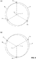
- FIGS. 6A and 6B individual reference numerals 31a, 31b, 31c have been assigned to the respective hook portions 31, with FIG. 6B showing a state that has been rotated by 60° from the state in FIG. 6A .
- the respective hook portions 31a, 31b, 31c would rotate along the dot-dot-dash line if there were no misalignment between the axes, after rotating by 60° the hook portion 31a for example shown in FIG. 6A swings to a position that is even further separated from the position shown by the dot-dot-dash line (see FIG. 6B ). That is, the respective engagement members 30 will swing during a driving operation.
- the rotation clamping mechanism 1 of the present embodiment minimizes the generation of vibration as described below. Accordingly, with a cold test apparatus that uses the rotation clamping mechanism 1 according to the present embodiment, the vibration transmitted to the rotated object during a cold test is minimized and it is possible to carry out more accurate cold tests for an engine to be tested.
- the three engagement members 30 positioned at the engagement position clamp the drive plate B in a floating state as described above. Accordingly, during a driving operation of the drive plate B by the rotation clamping mechanism 1, the respective engagement members 30 can independently follow the drive plate B and the clamping force (i.e., the reactive forces to both the biasing force of the biasing members 40 and the centrifugal forces due to the weight of the biasing members 40) of the respective hook portions 31 can always be kept constant (or substantially constant). This means that the clamping state is maintained without the clamping of the drive plate B by the respective engagement members 30 being influenced by vibration or the like of the engagement members 30. Accordingly, shaking at the contact positions between the hook portions 31 and the drive plate B is prevented.
- the clamping force i.e., the reactive forces to both the biasing force of the biasing members 40 and the centrifugal forces due to the weight of the biasing members 40
- the drive plate B when the drive plate B is clamped by the engagement members 30, the drive plate B is clamped with the engagement members 30 in a floating state where the cam rollers 52 are separated from the cam surfaces 33b of the engagement members 30 at the engagement position, which means that during a cold test, it is possible to drastically reduce the transmission of vibration of predetermined frequencies that accompany rotation of the rotating member 20 to the engagement members 30.
- the engagement members 30 apply only rotational forces and clamping forces to the drive plate B. In other words, only rotational forces and biasing forces for clamping are transmitted via the engagement members 30 to the drive plate B and there is no transmission of vibration frequencies that accompany rotation of the rotating member 20.
- each spring 41 of the biasing members 40 is a direction perpendicular to the axial direction of the rotational axis 11a of the rotating member 20 and a direction along a swinging plane 30d (see FIG. 5 ).
- the biasing members 40 are disposed so that the orientation of the biasing forces of the biasing members 40 are oriented along the swinging planes 30d.
- the position of the swinging axis 30b of the engagement member 30 is disposed so as to be offset from a midway position between the position of the hook portion 31 and the contact position of the head portion 42 on the biasing member 40 toward the biasing position. If the drive plate B is rotated in a state where there is misalignment between the center of the rotational axis 11a of the rotating member 20 and the center C of the drive plate B, the respective engagement members 30 will swing with different swinging phases when the rotating member 20 rotates, resulting in the risk of the center of gravity of the entire rotating part of the rotation clamping mechanism 1 fluctuating, which would cause vibration.
- the biasing position will fluctuate less than the fluctuation in the position of the hook portion 31 and there will be less fluctuation in the extension and contraction of the biasing member 40. It also becomes possible to reduce the length and size of the tail portion 33 of the engagement member 30. If it is possible to reduce the fluctuation in the extension and contraction of the biasing member 40 and to reduce the size of the tail portion 33, it will be possible to reliably reduce the fluctuation in the center of gravity of the rotating part of the rotation clamping mechanism 1, and the generation of vibration due to fluctuation in the center of gravity will be minimized.
- each biasing member 40 is disposed so that the biasing position (the contact position between the biasing member 40 and the biasing surface 33a of the tail portion 33 of the corresponding engagement member 30) is disposed closer to the rotational axis 11a of the rotating member 20 than the position of the swinging axis 30b. In this way, if each biasing member 40 is disposed at a position close to the rotational axis 11a, the configuration of the entire rotating member will be disposed at a position close to the rotational axis, which makes the rotating member 20 more compact and also lighter. Since the weight of the rotating member 20 is reduced, the inertia moment of the rotating member 20 is also reduced.
- rotation clamping mechanism is not limited to the mechanism in the embodiment described above. Mechanisms that have been modified within a range that does not depart from the scope of the present invention are also included in the range of the present invention.
- each engagement member 30 is constructed so as to include the cam groove 34 that is engaged by the cam roller 52, if a cam surface 33b with which the cam roller 52 can make sliding contact is formed, it is possible to use a construction that does not include the cam groove 34.
Landscapes
- Engineering & Computer Science (AREA)
- General Engineering & Computer Science (AREA)
- Mechanical Engineering (AREA)
- Physics & Mathematics (AREA)
- General Physics & Mathematics (AREA)
- Chemical & Material Sciences (AREA)
- Combustion & Propulsion (AREA)
- Testing Of Engines (AREA)
- Jigs For Machine Tools (AREA)
- Clamps And Clips (AREA)
Claims (5)
- Drehspannmechanismus, der enthält: ein Drehelement (20), das so eingebaut ist, dass es in Drehung angetrieben werden kann; und Eingriffselemente (30), die am Drehelement (20) befestigt sind und Drehkraft übertragen, wobei die Eingriffselemente (30) in Eingriff mit einem gedreht werdenden Gegenstand angeordnet sind, der in einer Ausführungsposition einer Kraftübertragung angeordnet ist, die in einer vorbestimmten Positionsbeziehung mit dem Eingriffselement (30) ist, und der gedreht werdende Gegenstand durch Drehen des Drehelements (20) gedreht wird, wobei
mindestens zwei Eingriffselemente (30) am Drehelement (20) befestigt sind, die Eingriffselemente (30) auf dem Drehelement (20) in einem Zustand getragen werden, in dem die Eingriffselemente (30) in eine Eingriffsposition, in der ein Eingriff stattfindet, wodurch es möglich ist, Kraft auf den gedreht werdenden Gegenstand zu übertragen, und in eine Freigabeposition schwingen können, in der der Eingriff gelöst wird,
wobei der Drehspannmechanismus weiter enthält: einen Öffnungs-/Schließmechanismus (52), der die Eingriffselemente (30) zwischen der Eingriffsposition und der Freigabeposition öffnet und schließt; und ein Vorspannelement (40), das die Eingriffselemente (30) zur Eingriffsposition hin vorspannt, und
wenn in der Eingriffsposition positioniert, die Vielzahl von Eingriffselementen (30) den gedreht werdenden Gegenstand in einem schwebenden Zustand einspannen, in dem die Eingriffselemente (30) durch das Vorspannelement (40) auf den gedreht werdenden Gegenstand gedrückt werden, dadurch gekennzeichnet, dass
eine Vorspannrichtung des Vorspannelements (40) eine Richtung lotrecht zu einer Achsrichtung einer Drehachse des Drehelements (20) und radial nach außen von der Drehachse (11a) ist, und eine Schwingebene jedes Eingriffselements (30) eine von einer Vorspannrichtung der auf das Eingriffselement (30) angewendeten Vorspannkraft und der axialen Richtung der Drehachse gebildete Ebene ist. - Drehspannmechanismus nach dem vorhergehenden Anspruch, wobei der Öffnungs-/Schließmechanismus (52) ein Anpresselement enthält, das gleitend eine Gleitfläche des Eingriffselements (30) kontaktiert, das Anpresselement eine Anpresskraft anwendet, die der Vorspannkraft des Vorspannelements (40) auf die Eingriffselemente (30) widersteht, und fähig ist, sich zwischen einer Anpressposition, die die Eingriffselemente (30) in der Freigabeposition positioniert, und einer Rückzugsposition zu bewegen, in der das Anpresselement von den Eingriffselementen (30) getrennt wird, und die in der Eingriffsposition positionierten Eingriffselemente (30) durch die Vorspannkraft des Vorspannelements (40) auf den gedreht werdenden Gegenstand in einem schwebenden Zustand gepresst werden.
- Drehspannmechanismus nach einem der vorhergehenden Ansprüche, wobei eine Schwingachsenposition jedes Eingriffselements (30) eine mittlere Position zwischen einer Kontaktposition des Eingriffselements (30) auf dem gedreht werdenden Gegenstand und einer Kontaktposition des Vorspannelements (40) auf dem Eingriffselement (30) ist, und so angeordnet ist, dass sie von einer mittleren Position versetzt ist, die den gleichen Abstand von beiden Kontaktpositionen zur Kontaktposition zwischen dem Vorspannelement (40) und dem Eingriffselement (30) hat.
- Drehspannmechanismus nach Anspruch 3, wobei das Vorspannelement (40) so angeordnet ist, dass die Kontaktposition mit jedem Eingriffselement (30) in der Vorspannrichtung näher an der Drehachse positioniert ist als die Schwingachsenposition des Vorspannelements (40).
- Drehtestvorrichtung für einen Verbrennungsmotor, die einen Drehspannmechanismus nach einem der vorhergehenden Ansprüche aufweist, wobei der gedreht werdende Gegenstand, in den die Eingriffselemente (30) eingreifen und ihn drehen sollen, eine Antriebsscheibe B eines Verbrennungsmotors ist.
Applications Claiming Priority (1)
| Application Number | Priority Date | Filing Date | Title |
|---|---|---|---|
| JP2013135653A JP5873460B2 (ja) | 2013-06-27 | 2013-06-27 | 回転挟持機構 |
Publications (3)
| Publication Number | Publication Date |
|---|---|
| EP2824345A2 EP2824345A2 (de) | 2015-01-14 |
| EP2824345A3 EP2824345A3 (de) | 2015-12-16 |
| EP2824345B1 true EP2824345B1 (de) | 2019-04-24 |
Family
ID=51210235
Family Applications (1)
| Application Number | Title | Priority Date | Filing Date |
|---|---|---|---|
| EP14174695.8A Not-in-force EP2824345B1 (de) | 2013-06-27 | 2014-06-27 | Drehbarer Spannmechanismus |
Country Status (4)
| Country | Link |
|---|---|
| US (1) | US9291209B2 (de) |
| EP (1) | EP2824345B1 (de) |
| JP (1) | JP5873460B2 (de) |
| CN (1) | CN104251267B (de) |
Families Citing this family (8)
| Publication number | Priority date | Publication date | Assignee | Title |
|---|---|---|---|---|
| JP6702618B2 (ja) * | 2016-11-24 | 2020-06-03 | ダイハツ工業株式会社 | エンジン試験駆動用アダプタ |
| CN107283263A (zh) * | 2017-06-16 | 2017-10-24 | 苏州泛能电力科技有限公司 | 应用于五金钳类工具磨削的转移装置及其方法 |
| CN108402798A (zh) * | 2018-04-12 | 2018-08-17 | 浙江工贸职业技术学院 | 一种创意产品用展示台 |
| JP7104328B2 (ja) | 2018-12-17 | 2022-07-21 | スター精密株式会社 | 旋盤 |
| JP7197781B2 (ja) * | 2018-12-17 | 2022-12-28 | スター精密株式会社 | 旋盤 |
| JP2020097076A (ja) * | 2018-12-17 | 2020-06-25 | スター精密株式会社 | 旋盤 |
| CN116677722B (zh) * | 2023-05-24 | 2025-10-17 | 中车太原机车车辆有限公司 | 一种铁路车辆控制系统用离合装置及铁路车辆 |
| CN118687845B (zh) * | 2024-08-26 | 2024-11-19 | 常州艾特检验检测技术服务有限公司 | 一种混动变速器空载试验平台及其使用方法 |
Family Cites Families (10)
| Publication number | Priority date | Publication date | Assignee | Title |
|---|---|---|---|---|
| GB399907A (en) * | 1931-05-09 | 1933-10-19 | Koenig & Bauer Schnellpressfab | Improvements in rotary intaglio printing machines |
| US3224701A (en) * | 1964-08-11 | 1965-12-21 | Arlie B Wynne | Roll lock-up |
| US3760919A (en) * | 1972-03-06 | 1973-09-25 | Simmons Co | Positive clutch with dual releasing cams |
| US3938634A (en) * | 1975-01-22 | 1976-02-17 | Clark Equipment Company | Clutch mechanism |
| US4277972A (en) * | 1979-12-06 | 1981-07-14 | Modular Data Systems, Inc. | Engine dynamometer |
| JPH0523869Y2 (de) * | 1986-12-22 | 1993-06-17 | ||
| JP3106604B2 (ja) * | 1991-10-22 | 2000-11-06 | 株式会社明電舎 | 回転軸の結合装置 |
| EP1693661B2 (de) * | 2003-12-12 | 2013-04-03 | Hirata Corporation | Testvorrichtung des motorantriebs |
| JP4408254B2 (ja) * | 2004-11-18 | 2010-02-03 | 株式会社小野測器 | 回転駆動装置 |
| JP5679562B2 (ja) * | 2011-02-24 | 2015-03-04 | 東芝三菱電機産業システム株式会社 | エンジン試験装置 |
-
2013
- 2013-06-27 JP JP2013135653A patent/JP5873460B2/ja active Active
-
2014
- 2014-06-27 EP EP14174695.8A patent/EP2824345B1/de not_active Not-in-force
- 2014-06-27 US US14/318,214 patent/US9291209B2/en not_active Expired - Fee Related
- 2014-06-27 CN CN201410302638.0A patent/CN104251267B/zh not_active Expired - Fee Related
Also Published As
| Publication number | Publication date |
|---|---|
| JP2015010903A (ja) | 2015-01-19 |
| JP5873460B2 (ja) | 2016-03-01 |
| CN104251267B (zh) | 2017-01-04 |
| EP2824345A3 (de) | 2015-12-16 |
| CN104251267A (zh) | 2014-12-31 |
| US9291209B2 (en) | 2016-03-22 |
| EP2824345A2 (de) | 2015-01-14 |
| US20150001029A1 (en) | 2015-01-01 |
Similar Documents
| Publication | Publication Date | Title |
|---|---|---|
| EP2824345B1 (de) | Drehbarer Spannmechanismus | |
| US9856955B2 (en) | Starter generator belt tensioner | |
| EP3039308B1 (de) | Isolator zur verwendung mit einem mittels einer motor-generator einheit unterstützten oder gestarteten motor oder einem motor mit einem endlostriebelement | |
| US9964920B2 (en) | Process cartridge and photosensitive drum driving component | |
| JP5200111B2 (ja) | 拡大可能プーリ | |
| KR20190006547A (ko) | 로터리 텐셔너 | |
| US20190331170A1 (en) | Gear power transmitting mechanism | |
| EP2816723A1 (de) | Drehkreuzmechanismus mit piezoelektrischen Stellgliedern | |
| KR101428182B1 (ko) | 변속기 입력축의 댐퍼 | |
| CN109555645B (zh) | 张紧传动装置、变桨系统以及风力发电机组 | |
| CN104428112B (zh) | 闭锁装置 | |
| KR101877103B1 (ko) | 변속기의 토크 측정 장치 | |
| JP2024079086A (ja) | ノブ保持構造及びスマートロック | |
| JP2004218677A (ja) | 駆動伝達装置 | |
| JP2009174112A (ja) | 練条機の支持体を固定するための装置 | |
| CN103852262B (zh) | 门部件开关试验装置及方法 | |
| JP2751348B2 (ja) | ローラの試験方法及び装置 | |
| US10161458B2 (en) | Structure for coupling rotary actuator to driven body | |
| JP6431491B2 (ja) | トルク変動吸収装置 | |
| CN103277456B (zh) | 发动机飞轮 | |
| KR20210115688A (ko) | 카메라 어셈블리 | |
| JP4396601B2 (ja) | エンジンのバランス修正方法 | |
| CN109555824B (zh) | 张紧传动装置、变桨系统以及风力发电机组 | |
| CN205161640U (zh) | 带有自动停止机构的钓机 | |
| Dong et al. | An Improved Design of the Engine Bench Test Tool for the Dual Mass Flywheel (DMF) |
Legal Events
| Date | Code | Title | Description |
|---|---|---|---|
| 17P | Request for examination filed |
Effective date: 20140627 |
|
| AK | Designated contracting states |
Kind code of ref document: A2 Designated state(s): AL AT BE BG CH CY CZ DE DK EE ES FI FR GB GR HR HU IE IS IT LI LT LU LV MC MK MT NL NO PL PT RO RS SE SI SK SM TR |
|
| AX | Request for extension of the european patent |
Extension state: BA ME |
|
| PUAI | Public reference made under article 153(3) epc to a published international application that has entered the european phase |
Free format text: ORIGINAL CODE: 0009012 |
|
| PUAL | Search report despatched |
Free format text: ORIGINAL CODE: 0009013 |
|
| AK | Designated contracting states |
Kind code of ref document: A3 Designated state(s): AL AT BE BG CH CY CZ DE DK EE ES FI FR GB GR HR HU IE IS IT LI LT LU LV MC MK MT NL NO PL PT RO RS SE SI SK SM TR |
|
| AX | Request for extension of the european patent |
Extension state: BA ME |
|
| RIC1 | Information provided on ipc code assigned before grant |
Ipc: F16D 11/10 20060101AFI20151110BHEP Ipc: F16D 11/12 20060101ALI20151110BHEP |
|
| R17P | Request for examination filed (corrected) |
Effective date: 20160429 |
|
| RBV | Designated contracting states (corrected) |
Designated state(s): AL AT BE BG CH CY CZ DE DK EE ES FI FR GB GR HR HU IE IS IT LI LT LU LV MC MK MT NL NO PL PT RO RS SE SI SK SM TR |
|
| STAA | Information on the status of an ep patent application or granted ep patent |
Free format text: STATUS: EXAMINATION IS IN PROGRESS |
|
| 17Q | First examination report despatched |
Effective date: 20180615 |
|
| GRAP | Despatch of communication of intention to grant a patent |
Free format text: ORIGINAL CODE: EPIDOSNIGR1 |
|
| STAA | Information on the status of an ep patent application or granted ep patent |
Free format text: STATUS: GRANT OF PATENT IS INTENDED |
|
| INTG | Intention to grant announced |
Effective date: 20181130 |
|
| GRAS | Grant fee paid |
Free format text: ORIGINAL CODE: EPIDOSNIGR3 |
|
| GRAA | (expected) grant |
Free format text: ORIGINAL CODE: 0009210 |
|
| STAA | Information on the status of an ep patent application or granted ep patent |
Free format text: STATUS: THE PATENT HAS BEEN GRANTED |
|
| AK | Designated contracting states |
Kind code of ref document: B1 Designated state(s): AL AT BE BG CH CY CZ DE DK EE ES FI FR GB GR HR HU IE IS IT LI LT LU LV MC MK MT NL NO PL PT RO RS SE SI SK SM TR |
|
| REG | Reference to a national code |
Ref country code: GB Ref legal event code: FG4D |
|
| REG | Reference to a national code |
Ref country code: CH Ref legal event code: EP |
|
| REG | Reference to a national code |
Ref country code: DE Ref legal event code: R096 Ref document number: 602014045209 Country of ref document: DE |
|
| REG | Reference to a national code |
Ref country code: AT Ref legal event code: REF Ref document number: 1124501 Country of ref document: AT Kind code of ref document: T Effective date: 20190515 Ref country code: IE Ref legal event code: FG4D |
|
| REG | Reference to a national code |
Ref country code: NL Ref legal event code: MP Effective date: 20190424 |
|
| REG | Reference to a national code |
Ref country code: LT Ref legal event code: MG4D |
|
| PG25 | Lapsed in a contracting state [announced via postgrant information from national office to epo] |
Ref country code: NL Free format text: LAPSE BECAUSE OF FAILURE TO SUBMIT A TRANSLATION OF THE DESCRIPTION OR TO PAY THE FEE WITHIN THE PRESCRIBED TIME-LIMIT Effective date: 20190424 |
|
| PG25 | Lapsed in a contracting state [announced via postgrant information from national office to epo] |
Ref country code: LT Free format text: LAPSE BECAUSE OF FAILURE TO SUBMIT A TRANSLATION OF THE DESCRIPTION OR TO PAY THE FEE WITHIN THE PRESCRIBED TIME-LIMIT Effective date: 20190424 Ref country code: FI Free format text: LAPSE BECAUSE OF FAILURE TO SUBMIT A TRANSLATION OF THE DESCRIPTION OR TO PAY THE FEE WITHIN THE PRESCRIBED TIME-LIMIT Effective date: 20190424 Ref country code: NO Free format text: LAPSE BECAUSE OF FAILURE TO SUBMIT A TRANSLATION OF THE DESCRIPTION OR TO PAY THE FEE WITHIN THE PRESCRIBED TIME-LIMIT Effective date: 20190724 Ref country code: SE Free format text: LAPSE BECAUSE OF FAILURE TO SUBMIT A TRANSLATION OF THE DESCRIPTION OR TO PAY THE FEE WITHIN THE PRESCRIBED TIME-LIMIT Effective date: 20190424 Ref country code: ES Free format text: LAPSE BECAUSE OF FAILURE TO SUBMIT A TRANSLATION OF THE DESCRIPTION OR TO PAY THE FEE WITHIN THE PRESCRIBED TIME-LIMIT Effective date: 20190424 Ref country code: HR Free format text: LAPSE BECAUSE OF FAILURE TO SUBMIT A TRANSLATION OF THE DESCRIPTION OR TO PAY THE FEE WITHIN THE PRESCRIBED TIME-LIMIT Effective date: 20190424 Ref country code: PT Free format text: LAPSE BECAUSE OF FAILURE TO SUBMIT A TRANSLATION OF THE DESCRIPTION OR TO PAY THE FEE WITHIN THE PRESCRIBED TIME-LIMIT Effective date: 20190824 Ref country code: AL Free format text: LAPSE BECAUSE OF FAILURE TO SUBMIT A TRANSLATION OF THE DESCRIPTION OR TO PAY THE FEE WITHIN THE PRESCRIBED TIME-LIMIT Effective date: 20190424 |
|
| PG25 | Lapsed in a contracting state [announced via postgrant information from national office to epo] |
Ref country code: BG Free format text: LAPSE BECAUSE OF FAILURE TO SUBMIT A TRANSLATION OF THE DESCRIPTION OR TO PAY THE FEE WITHIN THE PRESCRIBED TIME-LIMIT Effective date: 20190724 Ref country code: GR Free format text: LAPSE BECAUSE OF FAILURE TO SUBMIT A TRANSLATION OF THE DESCRIPTION OR TO PAY THE FEE WITHIN THE PRESCRIBED TIME-LIMIT Effective date: 20190725 Ref country code: LV Free format text: LAPSE BECAUSE OF FAILURE TO SUBMIT A TRANSLATION OF THE DESCRIPTION OR TO PAY THE FEE WITHIN THE PRESCRIBED TIME-LIMIT Effective date: 20190424 Ref country code: RS Free format text: LAPSE BECAUSE OF FAILURE TO SUBMIT A TRANSLATION OF THE DESCRIPTION OR TO PAY THE FEE WITHIN THE PRESCRIBED TIME-LIMIT Effective date: 20190424 Ref country code: PL Free format text: LAPSE BECAUSE OF FAILURE TO SUBMIT A TRANSLATION OF THE DESCRIPTION OR TO PAY THE FEE WITHIN THE PRESCRIBED TIME-LIMIT Effective date: 20190424 |
|
| REG | Reference to a national code |
Ref country code: AT Ref legal event code: MK05 Ref document number: 1124501 Country of ref document: AT Kind code of ref document: T Effective date: 20190424 |
|
| PG25 | Lapsed in a contracting state [announced via postgrant information from national office to epo] |
Ref country code: IS Free format text: LAPSE BECAUSE OF FAILURE TO SUBMIT A TRANSLATION OF THE DESCRIPTION OR TO PAY THE FEE WITHIN THE PRESCRIBED TIME-LIMIT Effective date: 20190824 |
|
| REG | Reference to a national code |
Ref country code: DE Ref legal event code: R097 Ref document number: 602014045209 Country of ref document: DE |
|
| PG25 | Lapsed in a contracting state [announced via postgrant information from national office to epo] |
Ref country code: SK Free format text: LAPSE BECAUSE OF FAILURE TO SUBMIT A TRANSLATION OF THE DESCRIPTION OR TO PAY THE FEE WITHIN THE PRESCRIBED TIME-LIMIT Effective date: 20190424 Ref country code: MC Free format text: LAPSE BECAUSE OF FAILURE TO SUBMIT A TRANSLATION OF THE DESCRIPTION OR TO PAY THE FEE WITHIN THE PRESCRIBED TIME-LIMIT Effective date: 20190424 Ref country code: DK Free format text: LAPSE BECAUSE OF FAILURE TO SUBMIT A TRANSLATION OF THE DESCRIPTION OR TO PAY THE FEE WITHIN THE PRESCRIBED TIME-LIMIT Effective date: 20190424 Ref country code: AT Free format text: LAPSE BECAUSE OF FAILURE TO SUBMIT A TRANSLATION OF THE DESCRIPTION OR TO PAY THE FEE WITHIN THE PRESCRIBED TIME-LIMIT Effective date: 20190424 Ref country code: RO Free format text: LAPSE BECAUSE OF FAILURE TO SUBMIT A TRANSLATION OF THE DESCRIPTION OR TO PAY THE FEE WITHIN THE PRESCRIBED TIME-LIMIT Effective date: 20190424 Ref country code: CZ Free format text: LAPSE BECAUSE OF FAILURE TO SUBMIT A TRANSLATION OF THE DESCRIPTION OR TO PAY THE FEE WITHIN THE PRESCRIBED TIME-LIMIT Effective date: 20190424 Ref country code: EE Free format text: LAPSE BECAUSE OF FAILURE TO SUBMIT A TRANSLATION OF THE DESCRIPTION OR TO PAY THE FEE WITHIN THE PRESCRIBED TIME-LIMIT Effective date: 20190424 |
|
| REG | Reference to a national code |
Ref country code: CH Ref legal event code: PL |
|
| PG25 | Lapsed in a contracting state [announced via postgrant information from national office to epo] |
Ref country code: SM Free format text: LAPSE BECAUSE OF FAILURE TO SUBMIT A TRANSLATION OF THE DESCRIPTION OR TO PAY THE FEE WITHIN THE PRESCRIBED TIME-LIMIT Effective date: 20190424 |
|
| PLBE | No opposition filed within time limit |
Free format text: ORIGINAL CODE: 0009261 |
|
| STAA | Information on the status of an ep patent application or granted ep patent |
Free format text: STATUS: NO OPPOSITION FILED WITHIN TIME LIMIT |
|
| GBPC | Gb: european patent ceased through non-payment of renewal fee |
Effective date: 20190724 |
|
| REG | Reference to a national code |
Ref country code: BE Ref legal event code: MM Effective date: 20190630 |
|
| PG25 | Lapsed in a contracting state [announced via postgrant information from national office to epo] |
Ref country code: TR Free format text: LAPSE BECAUSE OF FAILURE TO SUBMIT A TRANSLATION OF THE DESCRIPTION OR TO PAY THE FEE WITHIN THE PRESCRIBED TIME-LIMIT Effective date: 20190424 |
|
| 26N | No opposition filed |
Effective date: 20200127 |
|
| PG25 | Lapsed in a contracting state [announced via postgrant information from national office to epo] |
Ref country code: IE Free format text: LAPSE BECAUSE OF NON-PAYMENT OF DUE FEES Effective date: 20190627 Ref country code: GB Free format text: LAPSE BECAUSE OF NON-PAYMENT OF DUE FEES Effective date: 20190724 |
|
| PG25 | Lapsed in a contracting state [announced via postgrant information from national office to epo] |
Ref country code: LI Free format text: LAPSE BECAUSE OF NON-PAYMENT OF DUE FEES Effective date: 20190630 Ref country code: LU Free format text: LAPSE BECAUSE OF NON-PAYMENT OF DUE FEES Effective date: 20190627 Ref country code: BE Free format text: LAPSE BECAUSE OF NON-PAYMENT OF DUE FEES Effective date: 20190630 Ref country code: CH Free format text: LAPSE BECAUSE OF NON-PAYMENT OF DUE FEES Effective date: 20190630 Ref country code: SI Free format text: LAPSE BECAUSE OF FAILURE TO SUBMIT A TRANSLATION OF THE DESCRIPTION OR TO PAY THE FEE WITHIN THE PRESCRIBED TIME-LIMIT Effective date: 20190424 |
|
| PG25 | Lapsed in a contracting state [announced via postgrant information from national office to epo] |
Ref country code: FR Free format text: LAPSE BECAUSE OF NON-PAYMENT OF DUE FEES Effective date: 20190630 |
|
| PG25 | Lapsed in a contracting state [announced via postgrant information from national office to epo] |
Ref country code: CY Free format text: LAPSE BECAUSE OF FAILURE TO SUBMIT A TRANSLATION OF THE DESCRIPTION OR TO PAY THE FEE WITHIN THE PRESCRIBED TIME-LIMIT Effective date: 20190424 |
|
| PG25 | Lapsed in a contracting state [announced via postgrant information from national office to epo] |
Ref country code: MT Free format text: LAPSE BECAUSE OF FAILURE TO SUBMIT A TRANSLATION OF THE DESCRIPTION OR TO PAY THE FEE WITHIN THE PRESCRIBED TIME-LIMIT Effective date: 20190424 Ref country code: HU Free format text: LAPSE BECAUSE OF FAILURE TO SUBMIT A TRANSLATION OF THE DESCRIPTION OR TO PAY THE FEE WITHIN THE PRESCRIBED TIME-LIMIT; INVALID AB INITIO Effective date: 20140627 |
|
| PGFP | Annual fee paid to national office [announced via postgrant information from national office to epo] |
Ref country code: DE Payment date: 20210602 Year of fee payment: 8 Ref country code: IT Payment date: 20210511 Year of fee payment: 8 |
|
| PG25 | Lapsed in a contracting state [announced via postgrant information from national office to epo] |
Ref country code: MK Free format text: LAPSE BECAUSE OF FAILURE TO SUBMIT A TRANSLATION OF THE DESCRIPTION OR TO PAY THE FEE WITHIN THE PRESCRIBED TIME-LIMIT Effective date: 20190424 |
|
| REG | Reference to a national code |
Ref country code: DE Ref legal event code: R119 Ref document number: 602014045209 Country of ref document: DE |
|
| PG25 | Lapsed in a contracting state [announced via postgrant information from national office to epo] |
Ref country code: DE Free format text: LAPSE BECAUSE OF NON-PAYMENT OF DUE FEES Effective date: 20230103 |
|
| PG25 | Lapsed in a contracting state [announced via postgrant information from national office to epo] |
Ref country code: IT Free format text: LAPSE BECAUSE OF NON-PAYMENT OF DUE FEES Effective date: 20220627 |