EP2824006A1 - Fahrzeugbremssteuervorrichtung - Google Patents
Fahrzeugbremssteuervorrichtung Download PDFInfo
- Publication number
- EP2824006A1 EP2824006A1 EP13757090.9A EP13757090A EP2824006A1 EP 2824006 A1 EP2824006 A1 EP 2824006A1 EP 13757090 A EP13757090 A EP 13757090A EP 2824006 A1 EP2824006 A1 EP 2824006A1
- Authority
- EP
- European Patent Office
- Prior art keywords
- amount
- braking
- master
- cylinder pressure
- fluid
- Prior art date
- Legal status (The legal status is an assumption and is not a legal conclusion. Google has not performed a legal analysis and makes no representation as to the accuracy of the status listed.)
- Granted
Links
Images


Classifications
-
- B—PERFORMING OPERATIONS; TRANSPORTING
- B60—VEHICLES IN GENERAL
- B60T—VEHICLE BRAKE CONTROL SYSTEMS OR PARTS THEREOF; BRAKE CONTROL SYSTEMS OR PARTS THEREOF, IN GENERAL; ARRANGEMENT OF BRAKING ELEMENTS ON VEHICLES IN GENERAL; PORTABLE DEVICES FOR PREVENTING UNWANTED MOVEMENT OF VEHICLES; VEHICLE MODIFICATIONS TO FACILITATE COOLING OF BRAKES
- B60T13/00—Transmitting braking action from initiating means to ultimate brake actuator with power assistance or drive; Brake systems incorporating such transmitting means, e.g. air-pressure brake systems
- B60T13/10—Transmitting braking action from initiating means to ultimate brake actuator with power assistance or drive; Brake systems incorporating such transmitting means, e.g. air-pressure brake systems with fluid assistance, drive, or release
- B60T13/66—Electrical control in fluid-pressure brake systems
- B60T13/662—Electrical control in fluid-pressure brake systems characterised by specified functions of the control system components
-
- B—PERFORMING OPERATIONS; TRANSPORTING
- B60—VEHICLES IN GENERAL
- B60T—VEHICLE BRAKE CONTROL SYSTEMS OR PARTS THEREOF; BRAKE CONTROL SYSTEMS OR PARTS THEREOF, IN GENERAL; ARRANGEMENT OF BRAKING ELEMENTS ON VEHICLES IN GENERAL; PORTABLE DEVICES FOR PREVENTING UNWANTED MOVEMENT OF VEHICLES; VEHICLE MODIFICATIONS TO FACILITATE COOLING OF BRAKES
- B60T13/00—Transmitting braking action from initiating means to ultimate brake actuator with power assistance or drive; Brake systems incorporating such transmitting means, e.g. air-pressure brake systems
- B60T13/74—Transmitting braking action from initiating means to ultimate brake actuator with power assistance or drive; Brake systems incorporating such transmitting means, e.g. air-pressure brake systems with electrical assistance or drive
- B60T13/745—Transmitting braking action from initiating means to ultimate brake actuator with power assistance or drive; Brake systems incorporating such transmitting means, e.g. air-pressure brake systems with electrical assistance or drive acting on a hydraulic system, e.g. a master cylinder
-
- B—PERFORMING OPERATIONS; TRANSPORTING
- B60—VEHICLES IN GENERAL
- B60T—VEHICLE BRAKE CONTROL SYSTEMS OR PARTS THEREOF; BRAKE CONTROL SYSTEMS OR PARTS THEREOF, IN GENERAL; ARRANGEMENT OF BRAKING ELEMENTS ON VEHICLES IN GENERAL; PORTABLE DEVICES FOR PREVENTING UNWANTED MOVEMENT OF VEHICLES; VEHICLE MODIFICATIONS TO FACILITATE COOLING OF BRAKES
- B60T7/00—Brake-action initiating means
- B60T7/02—Brake-action initiating means for personal initiation
- B60T7/04—Brake-action initiating means for personal initiation foot actuated
- B60T7/042—Brake-action initiating means for personal initiation foot actuated by electrical means, e.g. using travel or force sensors
-
- B—PERFORMING OPERATIONS; TRANSPORTING
- B60—VEHICLES IN GENERAL
- B60T—VEHICLE BRAKE CONTROL SYSTEMS OR PARTS THEREOF; BRAKE CONTROL SYSTEMS OR PARTS THEREOF, IN GENERAL; ARRANGEMENT OF BRAKING ELEMENTS ON VEHICLES IN GENERAL; PORTABLE DEVICES FOR PREVENTING UNWANTED MOVEMENT OF VEHICLES; VEHICLE MODIFICATIONS TO FACILITATE COOLING OF BRAKES
- B60T13/00—Transmitting braking action from initiating means to ultimate brake actuator with power assistance or drive; Brake systems incorporating such transmitting means, e.g. air-pressure brake systems
- B60T13/02—Transmitting braking action from initiating means to ultimate brake actuator with power assistance or drive; Brake systems incorporating such transmitting means, e.g. air-pressure brake systems with mechanical assistance or drive
-
- B—PERFORMING OPERATIONS; TRANSPORTING
- B60—VEHICLES IN GENERAL
- B60T—VEHICLE BRAKE CONTROL SYSTEMS OR PARTS THEREOF; BRAKE CONTROL SYSTEMS OR PARTS THEREOF, IN GENERAL; ARRANGEMENT OF BRAKING ELEMENTS ON VEHICLES IN GENERAL; PORTABLE DEVICES FOR PREVENTING UNWANTED MOVEMENT OF VEHICLES; VEHICLE MODIFICATIONS TO FACILITATE COOLING OF BRAKES
- B60T13/00—Transmitting braking action from initiating means to ultimate brake actuator with power assistance or drive; Brake systems incorporating such transmitting means, e.g. air-pressure brake systems
- B60T13/74—Transmitting braking action from initiating means to ultimate brake actuator with power assistance or drive; Brake systems incorporating such transmitting means, e.g. air-pressure brake systems with electrical assistance or drive
-
- B—PERFORMING OPERATIONS; TRANSPORTING
- B60—VEHICLES IN GENERAL
- B60T—VEHICLE BRAKE CONTROL SYSTEMS OR PARTS THEREOF; BRAKE CONTROL SYSTEMS OR PARTS THEREOF, IN GENERAL; ARRANGEMENT OF BRAKING ELEMENTS ON VEHICLES IN GENERAL; PORTABLE DEVICES FOR PREVENTING UNWANTED MOVEMENT OF VEHICLES; VEHICLE MODIFICATIONS TO FACILITATE COOLING OF BRAKES
- B60T2270/00—Further aspects of brake control systems not otherwise provided for
- B60T2270/82—Brake-by-Wire, EHB
Definitions
- the present invention relates to a vehicle braking control device that generates force-multiplied brake hydraulic pressure in a master cylinder by an assist thrust imparted to an assist member in response to a movement of an input member.
- a vehicle braking control device uses an electric actuator to move an assist member in forward and backward directions, and multiplies the force to output a brake pedal input from a master cylinder (for example, see Patent Document 1).
- controlling the electric actuator makes it possible to vary the relative displacement between the input member that moves in the forward and backward directions by operating the brake pedal, and the assist member that moves relative to the input member, resulting in a desired braking characteristic.
- Patent Document 1 Patent 4784756 Publication
- a target degree of relative displacement is set based on an operating amount of the brake pedal, and the electric actuator is controlled so that the relationship of the degree of relative displacement between the input member and the assist member is at the target displacement amount, based on the degree of relative displacement or a displacement amount of the assist member.
- a characteristic representing the relationship between the brake fluid amount (hereinafter referred to as amount of fluid consumed by braking) that is supplied to a brake caliper in response to movement in the forward and backward directions of the input member and the assist member, and the master-cylinder pressure varies according to the resupply of brake fluid during a braking operation.
- amount of fluid consumed by braking a characteristic representing the relationship between the brake fluid amount (hereinafter referred to as amount of fluid consumed by braking) that is supplied to a brake caliper in response to movement in the forward and backward directions of the input member and the assist member, and the master-cylinder pressure varies according to the resupply of brake fluid during a braking operation.
- the master cylinder outputted from the master cylinder can be different.
- braking generated braking force
- the feeling of the pedal will vary relative to preset assumptions, if the electric actuator is controlled based on the degree of relative displacement between the input member and the assist member or the displacement amount of the assist member.
- the driver may experience an unpleasant feeling
- an object of the present invention is to provide a vehicle braking control device that controls braking and the feeling of the brake even if the relationship characteristics of the amount of fluid consumed by braking and the master-cylinder pressure vary.
- this vehicle braking control device is equipped with an input member, an assist member, a force-multiplying actuator, and a control means, a force-multiplied hydraulic brake pressure being generated in a master cylinder by an assist thrust imparted to the assist member in response to a movement of the input member, wherein the vehicle braking control device further comprises a reference map, an amount-of-fluid-consumed-in-braking-estimating means, and a master-cylinder pressure detection means.
- the input member is moved forward and backward by operation of the brake pedal.
- the assist member is disposed to be capable of moving in a relative manner with respect to a direction of movement of the input member.
- the force-multiplying actuator moves the assist member forward and backward, and varies the degree of relative displacement between the input member and the assist member.
- the reference map is preset with the characteristic representing the relationship between the amount of fluid consumed by braking and the master-cylinder pressure.
- the amount-of fluid-consumed-in-braking-estimating means calculates an estimated amount of fluid consumed by braking, which is the amount of fluid consumed in braking for implementing a braking force based on the brake pedal operating amount.
- the master-cylinder pressure-detection means detects the actual master-cylinder pressure.
- control means when the characteristic representing the relationship between the estimated amount of fluid consumed by braking and the actual master-cylinder pressure has a difference with regard to the reference map, sets a target value for the degree of relative displacement between the input member and the assist member based on the operating amount of the brake pedal, and corrects the degree of relative displacement between the input member and the assist member toward a direction to reduce characteristics differences, when controlling the force-multiplying actuator so that the degree of relative displacement matches the target value.
- the target value of the degree of relative displacement between the input member and the assist member is corrected by the control means in a direction in which the characteristics difference is reduced.
- the actual master-cylinder pressure becomes an ideal master-cylinder pressure (a reference master-cylinder pressure) with regard to the operating amount of the brake pedal, thereby controlling to vary the braking and pedal feel with regard to the assumption. This results in reducing an unpleasant sensation for the driver.
- Embodiment 1 a configuration of the vehicle braking control device according to Embodiment 1 will now be described focusing on a basic configuration of an electric vehicle, a configuration of a braking device, a configuration of a control system, and a configuration for calculating a target displacement correction amount.
- FIG. 1 is an overall view of an essential structure of an electric vehicle that has adopted the vehicle braking control device pursuant to Embodiment 1.
- an electric vehicle S pursuant to Embodiment 1 is equipped with a motor/generator 101; a reduction drive 102; a braking mechanism 103; left and right front wheels (drive wheels) FL, and FR; left and right rear wheels RL, and RR; and an integrated controller 110.
- the motor/generator 101 is a synchronous type motor/generator with a permanent magnet embedded in a rotor, and a stator coil wrapped around a stator. This is interlocked to the left and right front wheels FL, FR via the reduction drive 102. Also, the motor/generator 101 is controlled by charging a three-phase AC current created by a drive circuit 104, based on a control instruction from the integrated controller 110.
- the drive circuit 104 controls giving and receiving electrical power with a battery 105 composed of a lithium ion battery or the like, for the example.
- the motor/generator 101 acts as an electric motor that is rotatably driven by receiving a supply of electrical power from the battery, by the control of the drive circuit 104.
- the rotor receives rotating energy from the left and right front wheels FL and FR, which are the drive wheels, it is possible to charge the battery by functioning as an electric power generator that produces electromotive force at both ends of the stator coil.
- the drive circuit 104 adjusts so that a drive torque or regenerative torque that is produced by the motor/generator 101 matches the torque instruction value sent from the integrated controller 110.
- the braking mechanism 103 includes disc rotors 40a - 40d in a hydraulic braking system disposed on each FL, FR, RL, RR wheel, and a braking device 1.
- the braking device 1 activates a brake hydraulic on each of the disc rotors 40a - 40d in response to a braking operation implemented by the driver thereby imparting frictional braking torque on each of the FL, FR, RL, and RR wheels. Also, this controls frictional braking torque based on a regenerative coordinated control instruction from the integrated controller 110.
- the integrated controller 110 has a feature for driving the electric automobile S at maximum efficiency by controlling energy consumed by the entire vehicle.
- This inputs necessary information from a motor-speed sensor 121 that detects a motor speed Nm, and from a wheel-speed sensor 124 or the like that detects the wheel speeds of each of the right and left wheels FL and FR and the rear wheels RL, and RR, and information via a CAN communication line 130.
- this executes drive control or regenerative control at the motor/generator 101 by outputting a control instruction to the drive circuit 104, and executes braking control by outputting a control instruction to the braking device 1.
- the integrated controller 110 implements energy recovery with high energy recovery efficiency using regenerative braking up to a low vehicle speed, particularly in a driving pattern that repeats acceleration and deceleration, by distributing with priority to regenerative braking torque with regard to the target deceleration speed.
- an upper limit torque is established in correspondence with a speed determined by the vehicle speed. Accordingly, when the overall target deceleration speed cannot be completely covered only when decelerating to the target deceleration speed using the regenerative braking torque, a regenerative coordinated control instruction is outputted to the braking device 1 so that the deficit can be compensated for with the hydraulic braking torque using the braking mechanism 103.
- FIG. 2 is an overall structural view of a braking device in the vehicle braking control device pursuant to Embodiment 1.
- the braking device 1 includes a master cylinder 2; a reservoir tank RES; wheel cylinders 4a - 4d disposed on each of the FL, FR, RL, and RR wheels; a master-cylinder pressure-control mechanism 5 and input rod (input member) 6 disposed connected to the master cylinder 2; a brake-operation amount detection unit 7; and a master-cylinder pressure-control unit 8 that controls the master-cylinder pressure-control mechanism 5.
- the input rod 6 moderates a fluid pressure (hereinafter referred to as master-cylinder pressure Pmc) in the master cylinder 2 by cycling (advance or retreat) by operation of the brake pedal BP.
- master-cylinder pressure Pmc a fluid pressure
- the master-cylinder pressure-control mechanism 5 and the master-cylinder pressure-control unit 8 moderate the master-cylinder pressure Pmc by cycling the primary piston (assist member) 2b of the master cylinder 2.
- an X axis is set for an axial direction of the master cylinder 2; the brake pedal BP side is defined as a negative direction.
- the master cylinder 2 pursuant to Embodiment 1 is a so-called tandem type. This includes the primary piston (assist member) 2b and a secondary piston 2c in a cylinder body 2a.
- a primary hydraulic chamber 2d is formed as a first hydraulic chamber between an inner periphery of the cylinder body 2a, a face in a positive direction on the X axis of the primary piston 2b, and a face of the negative direction on the X axis of the secondary piston 2c.
- a secondary hydraulic chamber 2e is formed as a second hydraulic chamber between the inner periphery of the cylinder body 2a, and a face at a positive direction on the X axis of the secondary piston 2c.
- the primary hydraulic chamber 2d is communicably connected to a primary circuit 10 and the secondary hydraulic chamber 2e is communicably connected to the secondary circuit 20.
- the primary hydraulic chamber 2d volume varies by a stroke of the primary piston 2b and the secondary piston 2c inside the cylinder body 2a.
- a return spring 2f that urges the primary piston 2b in the negative direction on the X axis is disposed in the primary hydraulic chamber 2d.
- the secondary hydraulic chamber 2e volume varies by a stroke of the secondary piston 2c inside the cylinder body 2a.
- a return spring 2g that urges the secondary piston 2c in the negative direction on the X axis is disposed in the secondary hydraulic chamber 2e.
- various valves, motor pumps, reservoirs and the like are disposed on the primary circuit 10 and the secondary circuit 20 to implement ABS control and the like.
- a primary hydraulic sensor (master-cylinder pressure-detection means) 13 is disposed on the primary circuit 10; a secondary hydraulic sensor (master-cylinder pressure-detection means) 14 is disposed on the secondary circuit 20.
- the primary hydraulic sensor 13 detects fluid pressure in the primary hydraulic chamber 2d; the secondary hydraulic sensor 14 detects the fluid pressure in the secondary hydraulic chamber 2e. This fluid pressure information is sent to the master-cylinder pressure-control unit 8.
- a detection value (fluid pressure in the primary hydraulic chamber 2d) of the primary hydraulic sensor 13 is the master-cylinder pressure Pmc.
- One end 6a of the input rod 6 in the positive direction on the X axis is grounded inside the primary hydraulic chamber 2d, penetrating a bulkhead 2h of the primary piston 2b. A space between the end 6a of the input rod 6 and the bulkhead 2h of the primary piston 2b is sealed to ensure fluid tightness; the end 6a is disposed to be able to slide on the X axis direction in the bulkhead 2h. Conversely, another end 6b of the input rod 6 in the negative direction on the X axis is interlocked to the brake pedal BP. When the driver depresses the brake pedal BP, the input rod 6 moves in the positive direction on the X axis; when the driver returns the brake pedal BP, the input rod 6 moves in the negative direction on the X axis.
- a large diameter unit 6f is formed on the input rod 6, having a larger diameter than an inner periphery of the bulkhead 2h in the primary piston 2b, and a smaller diameter than an outer diameter of a plunge unit 6c.
- a gap L1 when the brake is not being activated, is disposed between a side face of the large diameter unit 6f in the positive direction on the X axis and a side face of the bulkhead 2h in the negative direction on the X axis. Because of this gap L1, it is possible to reduce a pressure of the hydraulic brake for the amount of regenerative braking by relative movement of the primary piston 2b in the negative direction on the X axis with regard to the input rod 6 when the regenerative coordinated control instruction is received from the integrated controller 110.
- Hydraulic fluid in the primary hydraulic chamber 2d is compressed by the input rod 6 or the primary piston 2b moving in the positive direction on the X axis thereby supplying compressed hydraulic fluid to the primary circuit 10.
- the secondary piston 2c moves in the positive direction on the X axis by compression of the primary hydraulic chamber 2d caused by the compressed hydraulic fluid.
- Operating fluid in the secondary hydraulic chamber 2e is compressed by the secondary piston 2c moving in the positive direction on the X axis thereby supplying compressed operating fluid to the secondary circuit 20.
- the brake-operation amount detection unit 7 detects the driver's required deceleration speed, and is disposed at the other end 6b of the input rod 6.
- the brake-operation amount detection unit 7 is a stroke sensor that detects a displacement amount (stroke) of the input rod 6 on the X axis direction; in other words, this is a stroke sensor for the brake pedal BP.
- the reservoir tank RES has at least two hydraulic chambers mutually partitioned by a bulkhead (not shown in the drawing). Each hydraulic chamber is communicably connected to the primary hydraulic chamber 2d and the secondary hydraulic chamber 2e of the master cylinder 2 via brake circuits 11 and 12.
- Wheel cylinders (frictional braking units) 4a - 4d include cylinders, pistons and pads and the like. The pistons are moved by operating fluid supplied to the cylinder unit 2a; pads that are interlocked to the pistons are pushed by the disc rotors 40a - 40d. Also, disc rotors 40a - 40d rotate as one body with each FL, FR, RL, RR wheel; braking torque that acts on the disc rotors 40a - 40d is the braking force that acts between each FL, FR, RL, RR wheel, and a road surface.
- the master-cylinder pressure-control mechanism 5 controls the displacement amount of the primary piston 2b that is proportional to the master-cylinder pressure Pmc according to a control instruction from the master-cylinder pressure-control unit 8, and includes the drive motor 50, a speed reducer 51, and a rotation-rectilinear transducer 55.
- the master-cylinder pressure-control unit 8 is an arithmetic processing circuit. It controls the actions of the drive motor 50 based on sensor signals and the like from the brake-operation amount detection unit 7 and the drive motor 50.
- the drive motor 50 is a three-phase, DC, brushless motor; it is operated by electric power that is supplied based on a control signal from the master-cylinder pressure-control unit 8 to generate the predetermined rotational torque.
- the speed reducer 51 reduces an output rotation of the drive motor 50 using a pulley deceleration method.
- the speed reducer 51 includes a small diameter drive-side pulley 52 disposed on an output shaft of the drive motor 50, a large diameter follower-side pulley 53 disposed on a ball-screw nut 56 on the rotation-rectilinear transducer 53, and a belt 54 trained around the drive side and follower side pulleys 52 and 53.
- the speed reducer 51 transmits rotational torque of the drive motor 50 to the rotation-rectilinear transducer 55 by amplifying only the deceleration ratio (a radius ratio of the drive side and follower side pulleys 52, and 53).
- the rotation-rectilinear transducer 55 converts the rotational power from the drive motor 50 into a rectilinear power. That rectilinear power pushes the primary piston 2b.
- a ball-screw method was adopted as the power-conversion mechanism.
- the rotation-rectilinear transducer 55 includes the ball-screw nut 56, a ball-screw shaft 57, a movable member 58, and a return spring 59.
- a first housing member HSG1 is connected to the negative direction of the master cylinder 2 on the X axis; a second housing member HSG2 is connected to the negative direction of the first housing member HSG1 on the X axis.
- the ball-screw nut 56 is disposed to be rotatable at an inner periphery of a bearing BRG disposed in the second housing member HSG2. At an outer circumference of the ball-screw nut 56 is fitted the follower side pulley 53. At an inner periphery of the ball-screw nut 56 is threaded a hollow ball-screw shaft 57. A plurality of holes is disposed to be able to rotate in a gap between the ball-screw nut 56 and the ball-screw shaft 57.
- the movable member 58 is integrated to an end of the ball-screw shaft 57 in positive direction on the X axis; the primary piston 2b is mated to a face of movable member 58 in the positive direction on the X axis.
- the primary piston 2b is housed inside the first housing member HSG1, and an end of the primary piston 2b in the positive direction on the X axis is fitted in the inner periphery of the primary piston 2b projecting from the first housing member HSG1.
- the return spring 59 is disposed at an outer circumference of the primary piston 2b inside the first housing member HSG1. One end of the return spring 59 is fastened to a face A inside the first housing member HSG1 in the positive direction on the X axis; one end engages the movable member 58 in the negative direction on the X axis.
- the return spring 59 is disposed to be pressed and collapsed between the face A and the movable member 58; it urges the movable member 58 and the ball-screw shaft 57 in the negative direction on the X axis.
- FIG. 2 shows a status where the ball-screw shaft 57 is at an initial position with maximum displacement in the negative direction on the X axis when the brake is not being operated.
- a pair of springs (urging means) 6d, and 6e are arranged in an annular gap B defined between the input rod 6 and the primary piston 2b.
- One end of each of the pair of springs 6d, and 6e is locked to a flange unit 6c disposed on the input rod 6; another end of the spring 6d is locked to the bulkhead 2h on the primary piston 2b; the other end of the spring 6e is locked to the movable member 58.
- the pair of springs 6d, and 6e urge the input rod 6 to the primary piston 2b toward a neutral position of the relative displacement of both, and function to hold the input rod 6 and the primary piston 2b in the neutral position of relative movement when there is no braking action.
- An urging force acts to return the input rod 6 to the neutral position with regard to the primary piston 2b when the input rod 6 and the primary piston 2b are relatively displaced in either direction from the neutral position, by one of these springs 6d, and 6e.
- a revolution-angle detection sensor (assist member movement amount detection means) 50a is disposed on the drive motor 50.
- a position signal of the motor output shaft detected by this is inputted to the master-cylinder pressure-control unit 8.
- the master-cylinder pressure-control unit 8 calculates the revolution angle of the drive motor 50 based on the inputted position signal, and calculates a drive amount of the rotation-rectilinear transducer 55, in other words, the displacement amount of the primary piston 2b on the X axis direction of the position, based on this revolution angle.
- the master-cylinder pressure-control unit 8 controls displacement of the primary piston 2b in response to the displacement of the input rod 6 by the drive motor 50. In other words, this controls the degree of relative displacement ⁇ X of the input rod 6 and the primary piston 2b.
- the master-cylinder pressure-control mechanism 5 and the master-cylinder pressure-control unit 8 are equipped with a target deceleration speed computing unit (not shown in the drawing) to calculating the target deceleration speed that is determined by the amount of displacement of the input rod 6 by the driver operating the brake. This also displaces the primary piston 2b in response to the target deceleration speed. This compresses the primary hydraulic chamber 2d by the thrusting force of the primary piston 2b by adding thrusting force of the input rod 6, and adjusts the master-cylinder pressure Pmc. In other words, the thrusting force of the input rod 6 is amplified.
- An amplification rate (hereinafter referred to as power assist ratio ⁇ ) is determined in the following way using a ratio and the like of the cross-sectional area in the axial direction (hereinafter referred to as pressure bearing areas AIR and APP) of the input rod 6 and the primary piston 2b in the primary hydraulic chamber 2d.
- the pressure bearing area AIR on the input rod 6 is set to be smaller than the pressure bearing area APP on the primary piston 2b.
- master-cylinder pressure characteristic means a change characteristic of the master-cylinder pressure Pmc with regard to the input rod stroke Xi. It is possible to attain a stroke characteristic that indicates the piston stroke Xb with regard to the input rod stroke Xi, and the target displacement amount calculation characteristic that indicates the change in the degree of relative displacement ⁇ x with regard to the input rod stroke Xi that corresponds to the target master-cylinder pressure characteristic. Calculate the target value of the degree of relative displacement ⁇ x (hereinafter referred to as the target degree of relative displacement ⁇ x*) based on the target displacement-amount calculation-characteristic data.
- one target degree of relative displacement ⁇ x* is defined with regard to the input rod stroke Xi, indicating the change characteristic of the target degree of relative displacement ⁇ x* with regard to the input rod stroke Xi, in the target displacement amount calculation characteristic.
- the input rod stroke Xi as described above is detected by the brake-operation amount detection unit 7, the piston stroke Xb is calculated based on a signal from the revolution-angle detection sensor 50a, and the degree of relative displacement ⁇ x can be found by a difference in the detected (calculated) displacement amount.
- power assist control set the target degree of relative displacement ⁇ x* based on the degree of relative displacement ⁇ x and the target displacement-amount calculation characteristics, and control (feedback control) the drive motor 50 so that the detected (calculated) degree of relative displacement ⁇ x matches the target degree of relative displacement ⁇ x*.
- Embodiment 1 because power assist control is implemented without using a depressing force sensor, the cost is reduced for that amount. Also, by controlling the drive motor 50 so that the degree of relative displacement ⁇ x becomes any optional, predetermined value, it is possible to attain a power assist ratio that is higher, or a power assist ratio that is lower than the power assist ratio determined by the pressure bearing area (AIR + APP) / AIR, and it is possible to attain a braking force based on the predetermined power assist ratio.
- Constant power assist control integrally displaces the input rod 6 and the primary piston 2b.
- the master-cylinder pressure Pmc generated along with the forward movement of the input rod 6 becomes larger in a quadratic curve, cubic curve or multidimensional curve (hereinafter referred to as these are collectively referred to as multi-order curves) that are a compound of high-order curves and the like that are higher than these.
- the power assist control sets the target degree of relative displacement ⁇ x* to a predetermined positive value and controls the drive motor 50 so that the degree of relative displacement ⁇ x becomes this predetermined value.
- the piston stroke Xb of the primary piston 2b increases compared to the input rod stroke Xi following the input rod 6 movement forward toward a direction to increase the master-cylinder pressure Pmc.
- the power assist ratio ⁇ becomes a size twice that of (1 + K ⁇ ⁇ x / FIR). In other words, this is synonymous to cycling the primary piston 2b only for an amount multiplying a proportional gain (1 + K ⁇ ⁇ x / FIR) by the input rod stroke Xi. In this way, the power assist ratio ⁇ is changed in response to the ⁇ x.
- the master-cylinder pressure-control mechanism 5 acts as a power assist source making it possible to generate a braking force as required by the driver and to attain a great reduction in pedal effort.
- the proportional gain (1 + K ⁇ ⁇ x / FIR) described above it is desirable for the proportional gain (1 + K ⁇ ⁇ x / FIR) described above to be 1.
- a braking force is temporarily required that is higher than the driver's brake operation amount, such as when emergency braking or the like, for example, it is possible to change the proportional gain to a value that exceeds 1.
- the power assist control is a method for controlling the drive motor 50 that advances forward movement of the primary piston 2b more with regard to the forward movement of the input rod 6, and the degree of relative displacement ⁇ x of the primary piston 2b with regard to the input rod 6 becomes larger along with the forward movement of the input rod 6.
- the increase in the master-cylinder pressure Pmc becomes higher than the constant power assist control along with the forward movement of the input rod 6.
- the increase in the master-cylinder pressure Pmc that is generated along with the forward movement (displacement in the positive direction on the X axis) of the input rod 6 becomes larger than the constant power assist control (the master-cylinder pressure characteristic that increases in the multidimensional curves is more precipitous).
- the power assist control includes a stroke characteristic where an increase in the piston stroke Xb is greater than one with regard to the increase in the input rod stroke Xi.
- the power assist variable control in addition to the control described above (controlling the drive motor 50 so that the piston stroke Xb is large compared to the input rod stroke Xi, following the movement of the input rod 6 in a direction to increase the master-cylinder pressure Pmc), this controls the drive motor 50 so that the piston stroke Xb becomes smaller compared to the input rod stroke Xi, following the movement of the input rod 6 in the direction to increase the Pmc.
- this it is possible to reduce frictional braking torque in response to the increase in the regenerative braking torque when implementing regenerative coordinated control.
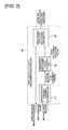
- FIG. 3 is a control block diagram of a target relative displacement-amount correction unit in the vehicle braking control device pursuant to Embodiment 1.
- the master-cylinder pressure-control unit 8 is equipped with a target relative displacement-amount correction unit (control means) 80, shown in FIG. 3 .
- the target relative displacement-amount correction unit 80 is equipped with a brake consumed fluid amount estimating unit (brake consumed fluid amount estimating means) 81, a correction-displacement amount calculating unit (correction-amount-calculating means) 82, and a target relative displacement-computing unit (target value correcting means) 83.
- the brake consumed fluid amount estimating unit 81 With the brake consumed fluid amount estimating unit 81, a target master-cylinder pressure Ps* that is required for implementing braking force is calculated based on a target deceleration speed computed by the target deceleration speed computing unit in response to an operating amount of the brake pedal BP detected by the brake-operation amount detection unit 7. Furthermore, the brake consumed fluid-amount estimating unit 81 includes a consumed fluid-amount fluid-pressure reference characteristic (reference map) that is a preset reference, and calculates the amount of fluid consumed by braking (estimated amount of fluid consumed by braking Q ⁇ ) that is required for generating the calculated target master-cylinder pressure Ps* from this consumed fluid-amount fluid-pressure reference characteristic.
- a consumed fluid-amount fluid-pressure reference characteristic reference map
- the amount of fluid consumed by braking is an amount of brake fluid supplied to the wheel cylinders 4a - 4d, by movement of the input rod 6 and the primary piston 2b.
- the consumed fluid-amount fluid-pressure reference characteristic is a reference map preset with relationship characteristics of the amount of fluid consumed by braking Q and the master-cylinder pressure Pmc.
- the consumed fluid-amount fluid-pressure reference characteristic has a characteristic that when the amount of fluid consumed by braking Q increases, the master-cylinder pressure Pmc increases. This is a characteristic of a multi-order curve that compounds high-order curves.
- the amount of fluid consumed by braking Q which is an intake characteristic in the consumed fluid-amount fluid-pressure reference characteristic is calculated based on equation (4) below, from the input rod stroke Xi, and the piston stroke Xb of the primary piston 2b.
- the master-cylinder pressure which is an output characteristic, use the actual master-cylinder pressure PmcA detected by the primary hydraulic sensor 13 and the secondary hydraulic sensor 14.
- Q Xi ⁇ AIR + Xb - ⁇ XRES ⁇ APP
- the correction-displacement amount calculating unit 82 calculates the target displacement-correction amount ⁇ x ⁇ which is a correction amount of the target degree of relative displacement ⁇ x*, so that the characteristics difference is reduced when a characteristics difference ⁇ V occurs between the estimated amount of fluid consumed by braking Q ⁇ calculated by the brake consumed fluid amount estimating unit 81 and a required amount of fluid consumed by braking Q1 found using the actual master-cylinder pressure PmcA and the consumed fluid amount fluid-pressure reference characteristic.
- the target relative displacement-computing unit 83 calculates the target degree of relative displacement ⁇ x** after correcting by subtracting from the target degree of relative displacement ⁇ x* the target displacement-correction amount ⁇ x ⁇ that was calculated by the correction-displacement amount calculating unit 82, and correcting the target degree of relative displacement ⁇ x*.
- FIG. 5 is a flowchart showing a flow of a calculating process of the target relative displacement correction amount executed by a brake controller in Embodiment 1. Each step depicted in FIG. 5 will now be described below.
- step S101 the amount of fluid consumed by braking (required amount of fluid consumed by braking Q1) required to generate the actual master-cylinder pressure PmcA is calculated using the detected master-cylinder pressure PmcA and the consumed fluid amount fluid-pressure reference characteristic that is a reference; thereafter the process shifts to step S102.
- the master-cylinder pressure PmcA is calculated based on the fluid pressure in the primary hydraulic chamber 2d detected by the primary hydraulic sensor 13, and the fluid pressure in the secondary hydraulic chamber 2e detected by the secondary hydraulic sensor 14.
- step S102 continuing from the calculation of the required amount of fluid consumed by braking Q1 at step S101, the amount of fluid consumed by braking change amount (increase/decrease amount)
- is calculated by subtracting the estimated amount of fluid consumed by braking Q ⁇ from the required amount of fluid consumed by braking Q1.
- step S103 continuing from calculating the amount of fluid consumed by braking change amount
- the change amount threshold th is set to any value, giving consideration to sensor error or variations in manufacturing and the like, for example. Also, it is acceptable to set the change amount threshold th to an offset with regard to the amount of change where the driver does not feel a change in the pedal feeling or the like.
- step S104 continuing from the judgment of change amount > change amount threshold th, the correction amount of the target degree of relative displacement ⁇ x* (target displacement-correction amount ⁇ x ⁇ ) is calculated at step S103. The process shifts to the end.
- the target displacement-correction amount ⁇ x ⁇ is found in the following way, for example.
- the master-cylinder pressure calculated based on the target deceleration speed found using the piston stroke Xb is the target master-cylinder pressure Ps*.
- the calculation of the master-cylinder pressure Ps* from the target deceleration speed is implemented using a coefficient found at that time, by pre-measuring a relationship between the deceleration speed and the pressure.
- Xi is expressed in equation (5) below as a function of the consumed fluid-amount fluid-pressure reference characteristic.
- Psa f ⁇ Xi , ⁇ x * - ⁇ x ⁇ , ⁇ V
- the depressing force is FIR* when the target master-cylinder pressure Ps* from the relationship in the pressure equilibrium equation (1).
- the fluid pressure FIRa that is required to generate the master-cylinder pressure Psa is calculated using the equation (7) below.
- FIRa Ps - AIR - K ⁇ ⁇ x * - ⁇ x ⁇ a
- FIRe FIR * - FIRa
- J P * - Pe T ⁇ R_ 1 ⁇ P * - Pe + FIR * - FIRe T ⁇ R_ 2 ⁇ FIR * - FIRe
- R_1 and R_2 are set by balancing so that the driver does not feel any unpleasantness in changes of the pedal feel.
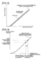
- FIG. 6 is a relationship characteristic map of the amount of fluid consumed by braking and master-cylinder pressure, showing an action of a target displacement correction implemented by the vehicle braking control device in Embodiment 1.
- the target degree of relative displacement ⁇ x* is set to correspond to the deceleration speed required by the driver found from the input rod 6 and the stroke Xi.
- the piston stroke Xb of the primary piston 2b is controlled so that the master-cylinder pressure (target master-cylinder pressure Ps*) is generated at a size that corresponds to the target degree of relative displacement ⁇ x*.
- the master-cylinder pressure (actual master-cylinder pressure PmcA) that is actually used is calculated at step S101 in the flowchart shown in FIG. 5 .
- step S102 finds the amount of fluid consumed by braking (required amount of fluid consumed by braking Q1) required to implement the detected actual master-cylinder pressure PmcA based on the consumed fluid amount fluid-pressure reference characteristic.
- step S103 finds the amount of fluid consumed by braking (estimated amount of fluid consumed by braking Q ⁇ ) required to implement the target master-cylinder pressure Ps* based on the consumed-fluid amount fluid-pressure reference characteristic. Also, the amount of fluid consumed by braking change amount
- the actual master-cylinder pressure PmcA that is actually occurring is a value that is larger than the target master-cylinder pressure Ps* (estimated master-cylinder pressure) found using the input rod stroke Xi. This indicates that the braking force on the input rod stroke Xi is higher than the reference. (See FIG. 7 )
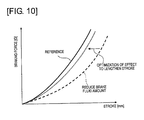
- the actual master-cylinder pressure PmcA that is actually occurring is a value that is smaller than the target master-cylinder pressure Ps* (estimated master-cylinder pressure) found using the input rod stroke Xi. This indicates that the braking force on the input rod 6 stroke Xi is lower than the reference. (See FIG. 10 )
- step S103 the process advances from step S103 to step S104 to calculate the correction amount of the target degree of relative displacement ⁇ x* (target displacement-correction amount ⁇ x ⁇ ).
- the target displacement-correction amount ⁇ x ⁇ is set in a direction to reduce the target degree of relative displacement ⁇ x*.
- the target displacement-correction amount ⁇ x ⁇ is set in a direction to increase the target degree of relative displacement ⁇ x*.
- the relationship of the stroke with the braking force and the relationship of the depressing force and the braking force are optimally distributed by setting the target displacement-correction amount ⁇ x ⁇ to a value where the evaluation function J shown in equation (9) is a minimum, giving consideration to the relationships of the stroke amount (input rod stroke Xi) of the brake pedal BP, the depressing force (input rod thrusting force FIR) of the brake pedal, and the braking force (master-cylinder pressure Pmc).
- the piston stroke Xb of the primary piston 2b is controlled so that the master-cylinder pressure Pmc is generated at a size that corresponds to the corrected target degree of relative displacement ⁇ x**.
- an amount of increase or decrease
- Embodiment 2 is an example where the target displacement-correction amount ⁇ x ⁇ is variable in response to a speed at which the driver operates the brake pedal.
- FIG. 11 is a control block diagram of a target degree of relative displacement correction unit in the vehicle braking control device pursuant to Embodiment 2.
- the vehicle braking control device pursuant to Embodiment 2 is equipped with a target relative displacement-amount correction unit 80A shown in FIG. 11 .
- the target relative displacement-amount correction unit 80A is equipped with a brake consumed fluid amount estimating unit 81, a corrected displacement-amount calculating unit 82A, a target relative displacement-computing unit 83, and a brake-operation speed estimating unit 84.
- the brake consumed fluid amount estimating unit 81 calculates the estimated amount of fluid consumed by braking Q ⁇ using the same procedures as those described in Embodiment 1. For that reason, a detailed description will be omitted. Also, the target relative displacement-computing unit 83 calculates the target degree of relative displacement ⁇ x** after correction using the same procedures as those described in Embodiment 1. For that reason, a detailed description will be omitted.
- the brake-operation speed estimating unit 84 estimates the pedal operation speed based on the operating amount (required deceleration speed) of the brake pedal BP detected by the brake-operation amount detection unit 7.
- estimation of the pedal operating speed is executed by a pseudo-differential operation that uses a high-pass filter, for example.
- the corrected displacement-amount calculating unit 82A includes a consumed fluid-amount fluid pressure reference characteristic preset for each operating speed of the brake pedal BP. Also, this switches the consumed fluid-amount fluid pressure reference characteristic that is applied when calculating the required amount of fluid consumed by braking Q1 in response to the estimated pedal operating speed estimated by the brake-operation speed estimating unit 84. Thereafter, the target displacement-correction amount ⁇ x ⁇ is calculated using the same procedure as in Embodiment 1.
- the target displacement-correction amount ⁇ x ⁇ varies in response to the magnitude of the estimated pedal operating speed. For that reason, it is possible to calculate the target displacement-correction amount ⁇ x ⁇ by considering an effect of the change in transitional master-cylinder pressure, when the brake pedal operating speed is fast and the master-cylinder pressure is transitionally high, more accurately to correct the target degree of relative displacement ⁇ x*. This results in inhibiting changes in braking and changes in the braking feeling, and inhibiting an unpleasant feeling sensed by the driver.
- the estimated pedal operating speed estimated by the brake-operation speed estimating unit 84 exceeds a preset threshold, it is acceptable to set the correction amount of the degree of relative displacement ⁇ x to a comparatively high value, compared to when the estimated pedal operating speed is below the threshold.
- the correction-amount-calculating means (corrected displacement-amount calculating unit) 82A is composed to increase or to decrease the correction amount ⁇ x ⁇ in response to the operating speed (estimated pedal operating speed) of the brake pedal BP.
Applications Claiming Priority (2)
| Application Number | Priority Date | Filing Date | Title |
|---|---|---|---|
| JP2012047798 | 2012-03-05 | ||
| PCT/JP2013/055715 WO2013133176A1 (ja) | 2012-03-05 | 2013-03-01 | 車両用制動制御装置 |
Publications (3)
| Publication Number | Publication Date |
|---|---|
| EP2824006A1 true EP2824006A1 (de) | 2015-01-14 |
| EP2824006A4 EP2824006A4 (de) | 2015-11-18 |
| EP2824006B1 EP2824006B1 (de) | 2017-05-03 |
Family
ID=49116656
Family Applications (1)
| Application Number | Title | Priority Date | Filing Date |
|---|---|---|---|
| EP13757090.9A Active EP2824006B1 (de) | 2012-03-05 | 2013-03-01 | Fahrzeugbremssteuervorrichtung |
Country Status (4)
| Country | Link |
|---|---|
| US (1) | US9452747B2 (de) |
| EP (1) | EP2824006B1 (de) |
| JP (1) | JP5800083B2 (de) |
| WO (1) | WO2013133176A1 (de) |
Cited By (3)
| Publication number | Priority date | Publication date | Assignee | Title |
|---|---|---|---|---|
| WO2017093040A1 (de) * | 2015-12-02 | 2017-06-08 | Continental Teves Ag & Co. Ohg | Bremsdrucksteuergerät |
| EP3279047A4 (de) * | 2015-12-07 | 2018-05-30 | Ningbo Tuopu Intelligent Brake System Co., Ltd. | Mechanische, elektrische und magnetische integrierte bremskraftverstärkervorrichtung |
| WO2019214835A1 (de) * | 2018-05-09 | 2019-11-14 | Ipgate Ag | Kolben-zylinder-system mit getrenntem lager- und dichtbereich |
Families Citing this family (12)
| Publication number | Priority date | Publication date | Assignee | Title |
|---|---|---|---|---|
| DE102012203698A1 (de) * | 2012-03-08 | 2013-09-12 | Robert Bosch Gmbh | Verfahren zum Betreiben eines Bremskraftverstärkers eines Fahrzeugs und Steuervorrichtung für einen Bremskraftverstärker eines Fahrzeugs |
| JP5898035B2 (ja) * | 2012-09-28 | 2016-04-06 | 日立オートモティブシステムズ株式会社 | ディスクブレーキ装置 |
| KR101478065B1 (ko) * | 2012-11-13 | 2015-01-02 | 주식회사 만도 | 전기 부스터 제어 장치 및 그 제어 방법 |
| JP6297344B2 (ja) * | 2014-01-31 | 2018-03-20 | 日立オートモティブシステムズ株式会社 | ブレーキ装置 |
| US10464536B2 (en) * | 2016-11-11 | 2019-11-05 | Honda Motor Co., Ltd. | Adaptive vehicle braking systems, and methods of use and manufacture thereof |
| CN106891899B (zh) * | 2017-02-15 | 2019-03-29 | 同济大学 | 纯电动汽车两档自动变速箱最佳经济性换挡规律计算方法 |
| KR102403612B1 (ko) * | 2017-04-24 | 2022-05-31 | 주식회사 만도 | 전자식 브레이크 시스템 및 그 제어 방법 |
| CN108791262B (zh) * | 2017-05-05 | 2022-04-01 | 罗伯特·博世有限公司 | 车辆制动系统的制动灯控制 |
| JP6747388B2 (ja) * | 2017-06-28 | 2020-08-26 | 株式会社アドヴィックス | 制動制御装置 |
| DE112018005492T5 (de) * | 2017-09-26 | 2020-10-15 | Hitachi Automotive Systems, Ltd. | Elektroverstärker |
| JP2020077260A (ja) * | 2018-11-08 | 2020-05-21 | 朝日電装株式会社 | 車両用制御システム |
| CN112918454B (zh) * | 2021-03-31 | 2021-12-07 | 东风汽车集团股份有限公司 | 线控制动系统状态的分析方法、系统及存储介质 |
Family Cites Families (7)
| Publication number | Priority date | Publication date | Assignee | Title |
|---|---|---|---|---|
| JP4631142B2 (ja) * | 2000-09-28 | 2011-02-16 | 日産自動車株式会社 | ブレーキ制御装置 |
| CN102320292B (zh) * | 2005-09-26 | 2014-06-11 | 株式会社日立制作所 | 电动助力装置 |
| JP4692833B2 (ja) * | 2006-04-28 | 2011-06-01 | 日立オートモティブシステムズ株式会社 | ブレーキ装置 |
| JP5262827B2 (ja) * | 2009-02-25 | 2013-08-14 | 日産自動車株式会社 | 車両用制動制御装置 |
| JP5241667B2 (ja) * | 2009-09-30 | 2013-07-17 | 日立オートモティブシステムズ株式会社 | ブレーキ制御システム |
| JP5672430B2 (ja) * | 2010-03-31 | 2015-02-18 | 日立オートモティブシステムズ株式会社 | ブレーキ制御装置 |
| JP5961513B2 (ja) * | 2012-09-28 | 2016-08-02 | 日立オートモティブシステムズ株式会社 | 車両制御装置およびブレーキ制御装置 |
-
2013
- 2013-03-01 JP JP2014503819A patent/JP5800083B2/ja active Active
- 2013-03-01 EP EP13757090.9A patent/EP2824006B1/de active Active
- 2013-03-01 WO PCT/JP2013/055715 patent/WO2013133176A1/ja active Application Filing
- 2013-03-01 US US14/374,571 patent/US9452747B2/en active Active
Cited By (4)
| Publication number | Priority date | Publication date | Assignee | Title |
|---|---|---|---|---|
| WO2017093040A1 (de) * | 2015-12-02 | 2017-06-08 | Continental Teves Ag & Co. Ohg | Bremsdrucksteuergerät |
| US10562506B2 (en) | 2015-12-02 | 2020-02-18 | Continental Teves Ag & Co. Ohg | Brake pressure control unit |
| EP3279047A4 (de) * | 2015-12-07 | 2018-05-30 | Ningbo Tuopu Intelligent Brake System Co., Ltd. | Mechanische, elektrische und magnetische integrierte bremskraftverstärkervorrichtung |
| WO2019214835A1 (de) * | 2018-05-09 | 2019-11-14 | Ipgate Ag | Kolben-zylinder-system mit getrenntem lager- und dichtbereich |
Also Published As
| Publication number | Publication date |
|---|---|
| US20150035352A1 (en) | 2015-02-05 |
| EP2824006B1 (de) | 2017-05-03 |
| CN104185581A (zh) | 2014-12-03 |
| US9452747B2 (en) | 2016-09-27 |
| JPWO2013133176A1 (ja) | 2015-07-30 |
| JP5800083B2 (ja) | 2015-10-28 |
| WO2013133176A1 (ja) | 2013-09-12 |
| EP2824006A4 (de) | 2015-11-18 |
Similar Documents
| Publication | Publication Date | Title |
|---|---|---|
| EP2824006B1 (de) | Fahrzeugbremssteuervorrichtung | |
| JP6236672B2 (ja) | 電動車両の制御装置 | |
| EP2213539B1 (de) | Bremsregelung für ein Fahrzeug | |
| US9714017B2 (en) | Brake controller | |
| JP6870101B2 (ja) | 電動倍力装置 | |
| JP6849822B2 (ja) | 電動倍力装置およびブレーキ制御装置 | |
| KR20140109277A (ko) | 브레이크 제어 장치 | |
| CN104973030A (zh) | 用于车辆的被设计成实现平滑减速的制动装置 | |
| JP2011031693A (ja) | ブレーキ制御システム | |
| JP5830965B2 (ja) | 制動力制御装置 | |
| JP6033645B2 (ja) | ブレーキ装置 | |
| JP5566873B2 (ja) | 車両用ブレーキ装置 | |
| JP5304273B2 (ja) | ブレーキ倍力装置の制御装置 | |
| US10556573B2 (en) | Braking control device for vehicle | |
| JP5262827B2 (ja) | 車両用制動制御装置 | |
| JP2015093586A (ja) | 車両用制動制御装置 | |
| JP5982885B2 (ja) | 制動制御装置 | |
| JP6049540B2 (ja) | ブレーキ制御装置 | |
| JP5245770B2 (ja) | ブレーキ倍力装置、ブレーキ倍力装置付き車両、およびブレーキ倍力方法 | |
| CN104185581B (zh) | 车辆用制动控制装置 | |
| KR101316584B1 (ko) | 차량 브레이크 시스템 및 그 제어 방법 | |
| JP6318586B2 (ja) | 車両用制動制御装置 |
Legal Events
| Date | Code | Title | Description |
|---|---|---|---|
| PUAI | Public reference made under article 153(3) epc to a published international application that has entered the european phase |
Free format text: ORIGINAL CODE: 0009012 |
|
| 17P | Request for examination filed |
Effective date: 20141001 |
|
| AK | Designated contracting states |
Kind code of ref document: A1 Designated state(s): AL AT BE BG CH CY CZ DE DK EE ES FI FR GB GR HR HU IE IS IT LI LT LU LV MC MK MT NL NO PL PT RO RS SE SI SK SM TR |
|
| AX | Request for extension of the european patent |
Extension state: BA ME |
|
| DAX | Request for extension of the european patent (deleted) | ||
| RA4 | Supplementary search report drawn up and despatched (corrected) |
Effective date: 20151015 |
|
| RIC1 | Information provided on ipc code assigned before grant |
Ipc: B60T 13/74 20060101AFI20151009BHEP Ipc: B60T 7/04 20060101ALI20151009BHEP |
|
| GRAP | Despatch of communication of intention to grant a patent |
Free format text: ORIGINAL CODE: EPIDOSNIGR1 |
|
| INTG | Intention to grant announced |
Effective date: 20161102 |
|
| GRAS | Grant fee paid |
Free format text: ORIGINAL CODE: EPIDOSNIGR3 |
|
| GRAA | (expected) grant |
Free format text: ORIGINAL CODE: 0009210 |
|
| AK | Designated contracting states |
Kind code of ref document: B1 Designated state(s): AL AT BE BG CH CY CZ DE DK EE ES FI FR GB GR HR HU IE IS IT LI LT LU LV MC MK MT NL NO PL PT RO RS SE SI SK SM TR |
|
| REG | Reference to a national code |
Ref country code: GB Ref legal event code: FG4D |
|
| REG | Reference to a national code |
Ref country code: AT Ref legal event code: REF Ref document number: 889613 Country of ref document: AT Kind code of ref document: T Effective date: 20170515 Ref country code: CH Ref legal event code: EP |
|
| REG | Reference to a national code |
Ref country code: IE Ref legal event code: FG4D |
|
| REG | Reference to a national code |
Ref country code: DE Ref legal event code: R096 Ref document number: 602013020653 Country of ref document: DE |
|
| REG | Reference to a national code |
Ref country code: NL Ref legal event code: MP Effective date: 20170503 |
|
| REG | Reference to a national code |
Ref country code: AT Ref legal event code: MK05 Ref document number: 889613 Country of ref document: AT Kind code of ref document: T Effective date: 20170503 |
|
| REG | Reference to a national code |
Ref country code: LT Ref legal event code: MG4D |
|
| PG25 | Lapsed in a contracting state [announced via postgrant information from national office to epo] |
Ref country code: AT Free format text: LAPSE BECAUSE OF FAILURE TO SUBMIT A TRANSLATION OF THE DESCRIPTION OR TO PAY THE FEE WITHIN THE PRESCRIBED TIME-LIMIT Effective date: 20170503 Ref country code: FI Free format text: LAPSE BECAUSE OF FAILURE TO SUBMIT A TRANSLATION OF THE DESCRIPTION OR TO PAY THE FEE WITHIN THE PRESCRIBED TIME-LIMIT Effective date: 20170503 Ref country code: NO Free format text: LAPSE BECAUSE OF FAILURE TO SUBMIT A TRANSLATION OF THE DESCRIPTION OR TO PAY THE FEE WITHIN THE PRESCRIBED TIME-LIMIT Effective date: 20170803 Ref country code: ES Free format text: LAPSE BECAUSE OF FAILURE TO SUBMIT A TRANSLATION OF THE DESCRIPTION OR TO PAY THE FEE WITHIN THE PRESCRIBED TIME-LIMIT Effective date: 20170503 Ref country code: GR Free format text: LAPSE BECAUSE OF FAILURE TO SUBMIT A TRANSLATION OF THE DESCRIPTION OR TO PAY THE FEE WITHIN THE PRESCRIBED TIME-LIMIT Effective date: 20170804 Ref country code: HR Free format text: LAPSE BECAUSE OF FAILURE TO SUBMIT A TRANSLATION OF THE DESCRIPTION OR TO PAY THE FEE WITHIN THE PRESCRIBED TIME-LIMIT Effective date: 20170503 Ref country code: LT Free format text: LAPSE BECAUSE OF FAILURE TO SUBMIT A TRANSLATION OF THE DESCRIPTION OR TO PAY THE FEE WITHIN THE PRESCRIBED TIME-LIMIT Effective date: 20170503 |
|
| PG25 | Lapsed in a contracting state [announced via postgrant information from national office to epo] |
Ref country code: PL Free format text: LAPSE BECAUSE OF FAILURE TO SUBMIT A TRANSLATION OF THE DESCRIPTION OR TO PAY THE FEE WITHIN THE PRESCRIBED TIME-LIMIT Effective date: 20170503 Ref country code: BG Free format text: LAPSE BECAUSE OF FAILURE TO SUBMIT A TRANSLATION OF THE DESCRIPTION OR TO PAY THE FEE WITHIN THE PRESCRIBED TIME-LIMIT Effective date: 20170803 Ref country code: NL Free format text: LAPSE BECAUSE OF FAILURE TO SUBMIT A TRANSLATION OF THE DESCRIPTION OR TO PAY THE FEE WITHIN THE PRESCRIBED TIME-LIMIT Effective date: 20170503 Ref country code: LV Free format text: LAPSE BECAUSE OF FAILURE TO SUBMIT A TRANSLATION OF THE DESCRIPTION OR TO PAY THE FEE WITHIN THE PRESCRIBED TIME-LIMIT Effective date: 20170503 Ref country code: RS Free format text: LAPSE BECAUSE OF FAILURE TO SUBMIT A TRANSLATION OF THE DESCRIPTION OR TO PAY THE FEE WITHIN THE PRESCRIBED TIME-LIMIT Effective date: 20170503 Ref country code: SE Free format text: LAPSE BECAUSE OF FAILURE TO SUBMIT A TRANSLATION OF THE DESCRIPTION OR TO PAY THE FEE WITHIN THE PRESCRIBED TIME-LIMIT Effective date: 20170503 Ref country code: IS Free format text: LAPSE BECAUSE OF FAILURE TO SUBMIT A TRANSLATION OF THE DESCRIPTION OR TO PAY THE FEE WITHIN THE PRESCRIBED TIME-LIMIT Effective date: 20170903 |
|
| REG | Reference to a national code |
Ref country code: FR Ref legal event code: PLFP Year of fee payment: 6 |
|
| PG25 | Lapsed in a contracting state [announced via postgrant information from national office to epo] |
Ref country code: SK Free format text: LAPSE BECAUSE OF FAILURE TO SUBMIT A TRANSLATION OF THE DESCRIPTION OR TO PAY THE FEE WITHIN THE PRESCRIBED TIME-LIMIT Effective date: 20170503 Ref country code: RO Free format text: LAPSE BECAUSE OF FAILURE TO SUBMIT A TRANSLATION OF THE DESCRIPTION OR TO PAY THE FEE WITHIN THE PRESCRIBED TIME-LIMIT Effective date: 20170503 Ref country code: CZ Free format text: LAPSE BECAUSE OF FAILURE TO SUBMIT A TRANSLATION OF THE DESCRIPTION OR TO PAY THE FEE WITHIN THE PRESCRIBED TIME-LIMIT Effective date: 20170503 Ref country code: DK Free format text: LAPSE BECAUSE OF FAILURE TO SUBMIT A TRANSLATION OF THE DESCRIPTION OR TO PAY THE FEE WITHIN THE PRESCRIBED TIME-LIMIT Effective date: 20170503 Ref country code: EE Free format text: LAPSE BECAUSE OF FAILURE TO SUBMIT A TRANSLATION OF THE DESCRIPTION OR TO PAY THE FEE WITHIN THE PRESCRIBED TIME-LIMIT Effective date: 20170503 |
|
| REG | Reference to a national code |
Ref country code: DE Ref legal event code: R097 Ref document number: 602013020653 Country of ref document: DE |
|
| PG25 | Lapsed in a contracting state [announced via postgrant information from national office to epo] |
Ref country code: SM Free format text: LAPSE BECAUSE OF FAILURE TO SUBMIT A TRANSLATION OF THE DESCRIPTION OR TO PAY THE FEE WITHIN THE PRESCRIBED TIME-LIMIT Effective date: 20170503 Ref country code: IT Free format text: LAPSE BECAUSE OF FAILURE TO SUBMIT A TRANSLATION OF THE DESCRIPTION OR TO PAY THE FEE WITHIN THE PRESCRIBED TIME-LIMIT Effective date: 20170503 |
|
| PLBE | No opposition filed within time limit |
Free format text: ORIGINAL CODE: 0009261 |
|
| STAA | Information on the status of an ep patent application or granted ep patent |
Free format text: STATUS: NO OPPOSITION FILED WITHIN TIME LIMIT |
|
| 26N | No opposition filed |
Effective date: 20180206 |
|
| PG25 | Lapsed in a contracting state [announced via postgrant information from national office to epo] |
Ref country code: SI Free format text: LAPSE BECAUSE OF FAILURE TO SUBMIT A TRANSLATION OF THE DESCRIPTION OR TO PAY THE FEE WITHIN THE PRESCRIBED TIME-LIMIT Effective date: 20170503 |
|
| REG | Reference to a national code |
Ref country code: CH Ref legal event code: PL |
|
| PG25 | Lapsed in a contracting state [announced via postgrant information from national office to epo] |
Ref country code: MC Free format text: LAPSE BECAUSE OF FAILURE TO SUBMIT A TRANSLATION OF THE DESCRIPTION OR TO PAY THE FEE WITHIN THE PRESCRIBED TIME-LIMIT Effective date: 20170503 |
|
| REG | Reference to a national code |
Ref country code: BE Ref legal event code: MM Effective date: 20180331 |
|
| REG | Reference to a national code |
Ref country code: IE Ref legal event code: MM4A |
|
| PG25 | Lapsed in a contracting state [announced via postgrant information from national office to epo] |
Ref country code: LU Free format text: LAPSE BECAUSE OF NON-PAYMENT OF DUE FEES Effective date: 20180301 |
|
| PG25 | Lapsed in a contracting state [announced via postgrant information from national office to epo] |
Ref country code: IE Free format text: LAPSE BECAUSE OF NON-PAYMENT OF DUE FEES Effective date: 20180301 |
|
| PG25 | Lapsed in a contracting state [announced via postgrant information from national office to epo] |
Ref country code: CH Free format text: LAPSE BECAUSE OF NON-PAYMENT OF DUE FEES Effective date: 20180331 Ref country code: BE Free format text: LAPSE BECAUSE OF NON-PAYMENT OF DUE FEES Effective date: 20180331 Ref country code: LI Free format text: LAPSE BECAUSE OF NON-PAYMENT OF DUE FEES Effective date: 20180331 |
|
| PG25 | Lapsed in a contracting state [announced via postgrant information from national office to epo] |
Ref country code: MT Free format text: LAPSE BECAUSE OF NON-PAYMENT OF DUE FEES Effective date: 20180301 |
|
| PG25 | Lapsed in a contracting state [announced via postgrant information from national office to epo] |
Ref country code: TR Free format text: LAPSE BECAUSE OF FAILURE TO SUBMIT A TRANSLATION OF THE DESCRIPTION OR TO PAY THE FEE WITHIN THE PRESCRIBED TIME-LIMIT Effective date: 20170503 |
|
| PG25 | Lapsed in a contracting state [announced via postgrant information from national office to epo] |
Ref country code: HU Free format text: LAPSE BECAUSE OF FAILURE TO SUBMIT A TRANSLATION OF THE DESCRIPTION OR TO PAY THE FEE WITHIN THE PRESCRIBED TIME-LIMIT; INVALID AB INITIO Effective date: 20130301 Ref country code: PT Free format text: LAPSE BECAUSE OF FAILURE TO SUBMIT A TRANSLATION OF THE DESCRIPTION OR TO PAY THE FEE WITHIN THE PRESCRIBED TIME-LIMIT Effective date: 20170503 |
|
| PG25 | Lapsed in a contracting state [announced via postgrant information from national office to epo] |
Ref country code: MK Free format text: LAPSE BECAUSE OF NON-PAYMENT OF DUE FEES Effective date: 20170503 Ref country code: CY Free format text: LAPSE BECAUSE OF FAILURE TO SUBMIT A TRANSLATION OF THE DESCRIPTION OR TO PAY THE FEE WITHIN THE PRESCRIBED TIME-LIMIT Effective date: 20170503 |
|
| PG25 | Lapsed in a contracting state [announced via postgrant information from national office to epo] |
Ref country code: AL Free format text: LAPSE BECAUSE OF FAILURE TO SUBMIT A TRANSLATION OF THE DESCRIPTION OR TO PAY THE FEE WITHIN THE PRESCRIBED TIME-LIMIT Effective date: 20170503 |
|
| PGFP | Annual fee paid to national office [announced via postgrant information from national office to epo] |
Ref country code: FR Payment date: 20230222 Year of fee payment: 11 |
|
| PGFP | Annual fee paid to national office [announced via postgrant information from national office to epo] |
Ref country code: GB Payment date: 20230222 Year of fee payment: 11 Ref country code: DE Payment date: 20230221 Year of fee payment: 11 |
|
| REG | Reference to a national code |
Ref country code: DE Ref legal event code: R084 Ref document number: 602013020653 Country of ref document: DE |
|
| REG | Reference to a national code |
Ref country code: GB Ref legal event code: 746 Effective date: 20230922 |