EP2822425B1 - Sitzrahmen mit niedrigem profil - Google Patents
Sitzrahmen mit niedrigem profil Download PDFInfo
- Publication number
- EP2822425B1 EP2822425B1 EP13757525.4A EP13757525A EP2822425B1 EP 2822425 B1 EP2822425 B1 EP 2822425B1 EP 13757525 A EP13757525 A EP 13757525A EP 2822425 B1 EP2822425 B1 EP 2822425B1
- Authority
- EP
- European Patent Office
- Prior art keywords
- positioning module
- wheelchair
- seat
- frame member
- frame
- Prior art date
- Legal status (The legal status is an assumption and is not a legal conclusion. Google has not performed a legal analysis and makes no representation as to the accuracy of the status listed.)
- Active
Links
- 238000000034 method Methods 0.000 claims description 8
- 238000009434 installation Methods 0.000 description 3
- 230000008901 benefit Effects 0.000 description 2
- 229910000831 Steel Inorganic materials 0.000 description 1
- 230000003028 elevating effect Effects 0.000 description 1
- 230000007246 mechanism Effects 0.000 description 1
- 230000004048 modification Effects 0.000 description 1
- 238000012986 modification Methods 0.000 description 1
- 239000010959 steel Substances 0.000 description 1
- 238000003466 welding Methods 0.000 description 1
Images


Classifications
-
- A—HUMAN NECESSITIES
- A61—MEDICAL OR VETERINARY SCIENCE; HYGIENE
- A61G—TRANSPORT, PERSONAL CONVEYANCES, OR ACCOMMODATION SPECIALLY ADAPTED FOR PATIENTS OR DISABLED PERSONS; OPERATING TABLES OR CHAIRS; CHAIRS FOR DENTISTRY; FUNERAL DEVICES
- A61G5/00—Chairs or personal conveyances specially adapted for patients or disabled persons, e.g. wheelchairs
- A61G5/10—Parts, details or accessories
- A61G5/1056—Arrangements for adjusting the seat
- A61G5/1059—Arrangements for adjusting the seat adjusting the height of the seat
-
- A—HUMAN NECESSITIES
- A61—MEDICAL OR VETERINARY SCIENCE; HYGIENE
- A61G—TRANSPORT, PERSONAL CONVEYANCES, OR ACCOMMODATION SPECIALLY ADAPTED FOR PATIENTS OR DISABLED PERSONS; OPERATING TABLES OR CHAIRS; CHAIRS FOR DENTISTRY; FUNERAL DEVICES
- A61G5/00—Chairs or personal conveyances specially adapted for patients or disabled persons, e.g. wheelchairs
- A61G5/10—Parts, details or accessories
- A61G5/1056—Arrangements for adjusting the seat
- A61G5/1075—Arrangements for adjusting the seat tilting the whole seat backwards
-
- A—HUMAN NECESSITIES
- A61—MEDICAL OR VETERINARY SCIENCE; HYGIENE
- A61G—TRANSPORT, PERSONAL CONVEYANCES, OR ACCOMMODATION SPECIALLY ADAPTED FOR PATIENTS OR DISABLED PERSONS; OPERATING TABLES OR CHAIRS; CHAIRS FOR DENTISTRY; FUNERAL DEVICES
- A61G5/00—Chairs or personal conveyances specially adapted for patients or disabled persons, e.g. wheelchairs
- A61G5/10—Parts, details or accessories
- A61G5/1091—Cushions, seats or abduction devices
-
- B—PERFORMING OPERATIONS; TRANSPORTING
- B62—LAND VEHICLES FOR TRAVELLING OTHERWISE THAN ON RAILS
- B62B—HAND-PROPELLED VEHICLES, e.g. HAND CARTS OR PERAMBULATORS; SLEDGES
- B62B1/00—Hand carts having only one axis carrying one or more transport wheels; Equipment therefor
- B62B1/10—Hand carts having only one axis carrying one or more transport wheels; Equipment therefor in which the load is intended to be transferred totally to the wheels
- B62B1/12—Hand carts having only one axis carrying one or more transport wheels; Equipment therefor in which the load is intended to be transferred totally to the wheels involving parts being adjustable, collapsible, attachable, detachable, or convertible
-
- A—HUMAN NECESSITIES
- A61—MEDICAL OR VETERINARY SCIENCE; HYGIENE
- A61G—TRANSPORT, PERSONAL CONVEYANCES, OR ACCOMMODATION SPECIALLY ADAPTED FOR PATIENTS OR DISABLED PERSONS; OPERATING TABLES OR CHAIRS; CHAIRS FOR DENTISTRY; FUNERAL DEVICES
- A61G5/00—Chairs or personal conveyances specially adapted for patients or disabled persons, e.g. wheelchairs
- A61G5/10—Parts, details or accessories
- A61G5/1056—Arrangements for adjusting the seat
- A61G5/1062—Arrangements for adjusting the seat adjusting the width of the seat
-
- A—HUMAN NECESSITIES
- A61—MEDICAL OR VETERINARY SCIENCE; HYGIENE
- A61G—TRANSPORT, PERSONAL CONVEYANCES, OR ACCOMMODATION SPECIALLY ADAPTED FOR PATIENTS OR DISABLED PERSONS; OPERATING TABLES OR CHAIRS; CHAIRS FOR DENTISTRY; FUNERAL DEVICES
- A61G5/00—Chairs or personal conveyances specially adapted for patients or disabled persons, e.g. wheelchairs
- A61G5/10—Parts, details or accessories
- A61G5/1056—Arrangements for adjusting the seat
- A61G5/1064—Arrangements for adjusting the seat adjusting the depth of the seat
-
- A—HUMAN NECESSITIES
- A61—MEDICAL OR VETERINARY SCIENCE; HYGIENE
- A61G—TRANSPORT, PERSONAL CONVEYANCES, OR ACCOMMODATION SPECIALLY ADAPTED FOR PATIENTS OR DISABLED PERSONS; OPERATING TABLES OR CHAIRS; CHAIRS FOR DENTISTRY; FUNERAL DEVICES
- A61G5/00—Chairs or personal conveyances specially adapted for patients or disabled persons, e.g. wheelchairs
- A61G5/10—Parts, details or accessories
- A61G5/1056—Arrangements for adjusting the seat
- A61G5/1067—Arrangements for adjusting the seat adjusting the backrest relative to the seat portion
-
- Y—GENERAL TAGGING OF NEW TECHNOLOGICAL DEVELOPMENTS; GENERAL TAGGING OF CROSS-SECTIONAL TECHNOLOGIES SPANNING OVER SEVERAL SECTIONS OF THE IPC; TECHNICAL SUBJECTS COVERED BY FORMER USPC CROSS-REFERENCE ART COLLECTIONS [XRACs] AND DIGESTS
- Y10—TECHNICAL SUBJECTS COVERED BY FORMER USPC
- Y10T—TECHNICAL SUBJECTS COVERED BY FORMER US CLASSIFICATION
- Y10T29/00—Metal working
- Y10T29/49—Method of mechanical manufacture
- Y10T29/49616—Structural member making
- Y10T29/49622—Vehicular structural member making
-
- Y—GENERAL TAGGING OF NEW TECHNOLOGICAL DEVELOPMENTS; GENERAL TAGGING OF CROSS-SECTIONAL TECHNOLOGIES SPANNING OVER SEVERAL SECTIONS OF THE IPC; TECHNICAL SUBJECTS COVERED BY FORMER USPC CROSS-REFERENCE ART COLLECTIONS [XRACs] AND DIGESTS
- Y10—TECHNICAL SUBJECTS COVERED BY FORMER USPC
- Y10T—TECHNICAL SUBJECTS COVERED BY FORMER US CLASSIFICATION
- Y10T29/00—Metal working
- Y10T29/49—Method of mechanical manufacture
- Y10T29/49826—Assembling or joining
Definitions
- Many conventional wheelchairs are modified to include after-market or third party modular positioning mechanisms installed beneath the seat to provide for adjustable tilting and/or elevation of the wheelchair seat.
- a positioning module Upon installation of a positioning module with the wheelchair, a seat frame is assembled on top of the positioning module, resulting in a raised position of the seat frame and an increased seat height on the apparatus.
- GB 2 098 935 relates to such a conventional wheelchair.
- a seat frame for use with a seating apparatus, such as, for example, a wheelchair.
- a seat frame is provided in a low profile configuration to reduce overall seat height.
- a low profile seat frame is configured to at least partially straddle a supporting portion of the seating apparatus, such as, for example, a positioning module installed on a wheelchair, thereby reducing the height of the seat frame on the apparatus.
- a wheelchair includes a chassis, a positioning module, a seat frame, and a seat.
- the positioning module is mounted to an upper portion of the chassis and is operable to adjust at least one of an angular position and an elevational position of a seating area of the positioning module.
- the seat frame includes a support member secured to and spanning the seating area of the positioning module and a front frame member secured to a front end of the support member and overhanging a front edge of the seating area of the positioning module, such that the seat frame at least partially straddles the positioning module.
- the front frame member is connected with and at least partially supports at least one of a side frame member, foot rest, leg rest and arm rest assembled with and supported by the front frame member.
- the seat is secured to an upper surface of the support member.
- a low profile seat frame for assembly with a positioning module of a seating apparatus includes a support plate and front, rear, and first and second side frame members.
- the support plate includes a horizontally extending planar portion defining a seating area and a downward extending front flange disposed along a front end of the planar portion.
- the front frame member is secured to the front flange of the support plate, and the rear frame member is secured to an upper surface of the planar portion along a rear end opposite the front end.
- the first and second side frame members each include a front extension arm telescopically received in a corresponding tubular end of the front frame member and a rear extension arm telescopically received in a corresponding tubular end of the rear frame member; wherein the front extension arm of each of the first and second side frame members is vertically offset from the corresponding rear extension arm to accommodate a vertical offset between the front and rear frame members.
- a method for installing on a wheelchair a positioning module operable to adjust at least one of an angular position and an elevational position of a seating area at least partially defined by an upper surface of the positioning module.
- the positioning module is assembled to a chassis of the wheelchair.
- a low profile seat frame is provided, and includes a support plate having opposed upper and lower surfaces, a front frame member secured to a front end of the support plate and extending beyond the lower surface of the support plate, and a rear frame member secured to the upper surface of the support plate at a rear end of the support plate.
- the low profile seat frame is secured to the positioning module, such that the support plate spans the seating area of the positioning module and the front frame member overhangs a front edge of the seating area. At least one of a side frame member, a foot rest, a leg rest, and an arm rest is assembled with the front frame member. A wheelchair seat is secured to the upper surface of the support plate.
- interconnection may be direct as between the components or may be indirect, such as through the use of one or more intermediary components.
- reference to a "member,” “component,” or “portion” shall not be limited to a single structural member, component, or element but can include an assembly of components, members or elements.
- Positioning modules for wheelchairs or other seating apparatuses are often assembled with the apparatus as an after-market modification, installed between the chassis and seat frame, for example, to provide for adjustable tilting and/or elevation of the seat frame.
- Such an installation increases the height of the seat frame on the apparatus. This increased height may result in reduced clearance for the seated user, for example, reduced clearance for the user's legs under tables, desks, and other obstructions.
- a low profile seat frame for use with seating apparatuses, such as, for example, wheelchairs.
- a low profile seat frame is configured to at least partially straddle or overhang a seat supporting positioning module of the apparatus, such as, for example, a seat elevating and/or seat tilting positioning module.
- a seat supporting positioning module of the apparatus such as, for example, a seat elevating and/or seat tilting positioning module.
- This arrangement reduces the height of the seat frame on the seating apparatus by at least partially receiving or overlapping the positioning module with the seat frame.
- a wheelchair or other such seating apparatus may be retrofit with a positioning module by removing the seat and seat frame from the chassis, assembling the positioning module to the chassis, assembling the low profile seat frame to the positioning module, and assembling the seat to the low profile seat frame.
- FIG. 1 schematically illustrates a low profile seat frame 10 assembled with a positioning module 5 (or other such structure defining a seating area) of a seating apparatus, in accordance with an exemplary embodiment of the present application.
- the positioning module is secured to a chassis 3 or other such base of the seating or wheelchair apparatus.
- the seat frame 10 includes a central support member 12 sized to span a seating area of the positioning module 5, and a front frame member 14 secured to a front end of the support member 12 (e.g., secured to a downward front flange) and positioned to at least partially overhang a front edge or side 4 of the positioning module 5, such that the seat frame 10 at least partially straddles or receives the positioning module 5.
- an upper surface of the front frame member 14 is aligned with or recessed from a upper surface of the support member 12.
- the front frame member 14 may be used to support one or more of a seat (e.g., seat pan, seat cushion), leg rests, footrests, arm rests, or other components of the seating apparatus.
- the support member 12 may be provided as one or more plates, rails, tubes or other such structures.
- the support member 12 may be provided as a relatively thin, flat component (e.g., a 3.175 mm (1/8 inch) thick steel plate) to reduce the profile of the seating assembly, while maintaining rigid support for the seat frame 10.
- the front frame member 14 may be provided as a relatively thick (as compared to the support member) bar, tube (e.g., square or cylindrical tube, e.g., a 25.4 mm (1 inch) wide/diameter square/cylindrical tube), or other such component, sized to facilitate the support of and/or connection to other components of the apparatus.
- tube e.g., square or cylindrical tube, e.g., a 25.4 mm (1 inch) wide/diameter square/cylindrical tube
- the height or elevation of the seat may be reduced, as compared to a seat assembly in which the seat frame is disposed entirely on top of the positioning module.
- a rear frame member 16 may similarly be secured to a rear end of the support member 12 (e.g., secured to a downward rear flange) and positioned to at least partially overhang a rear edge or side 6 of the positioning module 5, such that the seat frame 10 fully spans a length of the positioning module 5.
- the rear frame member 16 may be positioned such that an upper surface of the rear frame member 16 is aligned with or recessed from the upper surface of the support member 12.
- the rear frame member 16 may be used to support a seat (e.g., seat pan, seat cushion), backrests, armrests, or other components of the seating apparatus.
- the rear frame member 16 may be provided as a relatively thick (as compared to the support member) bar, tube (e.g., square or cylindrical tube, e.g., a 25.4 mm (1 inch) wide/diameter square/cylindrical tube), or other such component, sized to facilitate the support of and/or connection to other components of the apparatus.
- tube e.g., square or cylindrical tube, e.g., a 25.4 mm (1 inch) wide/diameter square/cylindrical tube
- other such component sized to facilitate the support of and/or connection to other components of the apparatus.
- a seat frame 20 may include a rear frame member 26 secured to a rear end of the support member 22 and positioned such that the rear frame member 26 is disposed entirely above the positioning module 5 when the seat frame 20 is installed on the positioning module 5. Because the rear frame member 26 is located behind a seating area S of the seat frame 20, the elevated position of the rear frame member 26 does not affect the height of the seat.
- a low profile seat frame may additionally or alternatively include one or more side frame members secured to side ends of a support member.
- the side frame members may be configured to support a seat pan, armrests, backrests, or other components of a seating apparatus.
- Figure 3 schematically illustrates an exemplary low profile seat frame 30 assembled with a positioning module 5 of a seating apparatus, in accordance with an exemplary embodiment of the present application.
- the seat frame 30 includes a central support member 32 sized to span a width of the positioning module 5, and first and second side frame members 37, 39 secured to first and second side ends of the support member 32 (e.g., secured to downward side flanges) and positioned to at least partially overhang first and second sides or edges 7, 9 of the positioning module 5, such that the seat frame 30 straddles or receives the positioning module 5.
- first and second side frame members 37, 39 secured to first and second side ends of the support member 32 (e.g., secured to downward side flanges) and positioned to at least partially overhang first and second sides or edges 7, 9 of the positioning module 5, such that the seat frame 30 straddles or receives the positioning module 5.
- one or more side frame members may be detached from a support member and secured to a front frame member and/or rear frame member, for example, to provide rigid support for a seat that is substantially wider than the positioning module.
- FIG 4 schematically illustrates an exemplary low profile seat frame 40 assembled with a positioning module 5 of a seating apparatus, in accordance with an exemplary embodiment of the present application.
- the seat frame 40 includes a central support member 42 sized to span a width of the positioning module 5, and first and second side frame members 47, 49 secured to front and rear frame members 44, 46 and detached (and, optionally, spaced apart) from the support member 42.
- the side frame members 47, 49 are positioned to at least partially overhang first and second side edges 7, 9 of the positioning module 5, such that the seat frame 40 straddles or receives the positioning module 5.
- side frame members may be detachable and/or adjustable on the front and rear frame members.
- the front and rear frame members are hollow or tubular to receive arm extensions of the side frame members in telescoping engagement, to permit adjustment of the width of the seat frame.
- Fasteners e.g., bolts, retaining pins
- side frame members may be provided with hollow arm extensions to telescopically receive ends of the front and rear frame members.
- Other adjustable arrangements can also be used such as, for example, overlapping brackets and fasteners.
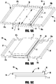
- FIGS 5A, 5B, and 5C illustrate various views of a low profile seat frame 50 assembled with a positioning module (shown schematically at 5) for installation on a seating apparatus (e.g., on a wheelchair 100, as shown in Figures 6A and 6B ), in accordance with an exemplary embodiment of the present application.
- the seat frame 50 includes a central support plate 52 sized to span a length of the positioning module 5 at least corresponding to a seating area of the seat frame, and a tubular front frame member 54 (e.g., a 25.4 mm (1 inch) wide square tube) secured to a front end of the support plate 52 and positioned to at least partially overhang a front edge or side 4 of the positioning module 5.
- a tubular front frame member 54 e.g., a 25.4 mm (1 inch) wide square tube
- the exemplary support plate includes a downward extending front flange 51 that is fastened (e.g., welded or otherwise attached) to the front frame member 54, with an upper surface of the front frame member 54 being substantially aligned with an upper surface of the support plate 52.
- the support plate may additionally include downward extending side flanges 58 positioned to closely receive sides or edges 7, 9 of the positioning module 5, for example, to provide additional rigid support of the support plate 52 against lateral movement on the positioning module 5.
- the support plate 52 may additionally be secured to the positioning module 5 by fasteners extending through mounting holes in the support plate 52 (e.g., fasteners securing a seat pan or seat cushion to the positioning module 5).
- the exemplary seat frame 50 includes a tubular rear frame member 56 (e.g., a 25.4 mm (1 inch) wide square tube) secured to the upper surface of the support plate 52 (e.g., by welding) along a rear end of the support plate 52, beyond the seating area S of the seat frame 50. As a result, the rear frame member 56 is raised or elevated with respect to the front frame member 54.
- a tubular rear frame member 56 e.g., a 25.4 mm (1 inch) wide square tube
- the exemplary seat frame 50 further includes first and second telescoping side frame members 57, 59 each having front arm extensions 57a, 59a sized and positioned to be received in the hollow or tubular ends of the front frame member 54, and rear arm extensions 57b, 59b sized and positioned to be received in the hollow or tubular ends of the rear frame member 56.
- the rear arm extensions 57b, 59b may be similarly offset in elevation with respected to the front arm extensions 57a, 59a, as evident in Figures 5A-5C .
- the front arm extensions 57a, 59a may be stepped down from an upper surface of the corresponding side frame member 57, 59, and the rear arm extensions 57b, 59b may extend upward from the upper surface of the corresponding side frame member 57, 59.
- the arm extensions 57a, 59a, 57b, 59b are laterally telescoped within the corresponding front and rear frame members 54, 56 to desired positions, which may, but need not, be substantially symmetrical.
- fasteners may be installed through aligned mounting holes in the front and rear frame members 54, 56 and the arm extensions 57a, 59a, 57b, 59b.
- a low profile seat frame 50' may utilize a narrower front frame member 54' secured to the front of the support plate 52', to further limit the portion of the seating area S' extending beyond the front of the positioning module (not shown), for example, to reduce the resulting load on the positioning module by the occupant of the wheelchair.
- the front frame member 54' may be formed from a 25.4 mm by 12.7 mm (1 inch by 1/2 inch) rectangular tube, for telescoping engagement with front arm extensions 57a', 59a' of the side frame members 57', 59'.
- the rear frame member 56' being positioned behind the seating area S' may, but need not, utilize a wider component (e.g., a 25.4 mm (1 inch) 'diameter cylindrical tube).
- a low profile seat frame 150 is provided, and includes a support plate 152 having opposed upper and lower surfaces, a front frame member 154 secured to a front end of the support plate 152 and extending beyond the lower surface of the support plate, and a rear frame member 156 secured to the upper surface of the support plate at a rear end of the support plate 152.
- the low profile seat frame 150 is secured to the positioning module 105, such that the support plate 152 spans the seating area of the positioning module and the front frame member 154 overhangs a front edge of the seating area.
- First and second side frame members 157, 159 are assembled with the front and rear frame members 154, 156 by inserting front extension arms 157a, 159a of the first and second side frame members 157, 159 into hollow ends of the front frame member 154, and inserting rear extension arms 157b, 159b of the first and second side frame members into hollow ends of the rear frame member 156.
- the side frame members are telescopically adjusted with respect to the front and rear frame members to define a desired width of a seating area, and the side frame members are secured in the selected positions (e.g., using fasteners assembled with the front and rear frame members).
- a backrest assembly 170 is secured to the rear frame member 156 (e.g., using brackets 171), and a leg rest assembly 180 is secured to the side frame members 157, 159 (e.g., using a support bar 181 installed between the side frame members and mounting brackets 182 secured to the support bar).
- a seat e.g., a seat pan and seat cushion, shown schematically in phantom at 190
- the support plate 152 e.g., using fasteners.
- FIGS 8A, 8B, and 8C illustrate a positioning module 5 assembled with an exemplary seat frame 60 having telescoping side frame members 67, 69 and utilizing a conventional non-low profile configuration.
- the tubular front and rear frame members 64, 66 and connecting cross bars 62a, 62b are all disposed directly on the upper surface of the positioning module 5, creating a higher profile or elevated seating area.
Landscapes
- Life Sciences & Earth Sciences (AREA)
- Animal Behavior & Ethology (AREA)
- General Health & Medical Sciences (AREA)
- Public Health (AREA)
- Veterinary Medicine (AREA)
- Health & Medical Sciences (AREA)
- Engineering & Computer Science (AREA)
- Chemical & Material Sciences (AREA)
- Combustion & Propulsion (AREA)
- Transportation (AREA)
- Mechanical Engineering (AREA)
- Seats For Vehicles (AREA)
- Chair Legs, Seat Parts, And Backrests (AREA)
Claims (14)
- Ein Rollstuhl, umfassend:ein Gestell (3, 101);ein Positionierungsmodul (5, 105), das an einem oberen Abschnitt des Gestells montiert ist, wobei das Positionierungsmodul betreibbar ist, mindestens eine von einer Winkelposition und einer Höhenposition eines Sitzbereichs des Positionierungsmoduls einzustellen;einen Sitzrahmen (10, 20, 30, 40, 50, 50', 150), umfassend:dadurch gekennzeichnet, dass:
ein Stützelement (12, 22, 32, 42, 52, 52', 152), das am Sitzbereich des Positionierungsmoduls befestigt ist und diesen überspannt;der Sitzrahmen ferner ein vorderes Rahmenelement (14, 24, 44, 54, 54', 154) umfasst, das an einem vorderen Endabschnitt des Stützelements befestigt ist und von einem vorderen Rand (4) des Sitzbereichs des Positionierungsmoduls derart überhängt, dass der Sitzrahmen mindestens teilweise das Positionierungsmodul übergreift, wobei das vordere Rahmenelement mit mindestens einem von einem seitlichen Rahmenelement (37, 39, 47, 49, 57, 59, 57', 59', 157, 159), einer Fußauflage, einer Beinauflage (180) und einer Armauflage verbunden ist und diese mindestens teilweise stützt, die mit dem vorderen Rahmenelement zusammengefügt ist und von diesem gestützt wird; undeinen Sitz (190), der an einer oberen Fläche des Stützelements befestigt ist;wobei sich eine obere Fläche des vorderen Rahmenelements nicht über einer oberen Fläche des Stützelements erstreckt. - Der Rollstuhl nach Anspruch 1, wobei der Sitzrahmen ferner ein hinteres Rahmenelement (16, 26, 46, 56, 56', 156) umfasst, das an einer oberen Fläche des Stützelements entlang eines hinteren Endes des Stützelements befestigt ist.
- Der Rollstuhl nach Anspruch 2, wobei der Sitzrahmen ferner erste und zweite seitliche Rahmenelemente (37, 39, 47, 49, 57, 59, 57', 59', 157, 159) umfasst, die mit dem vorderen und hinteren Rahmenelement zusammengefügt sind, um eine Breite des Sitzrahmens zu definieren.
- Der Rollstuhl nach Anspruch 3, wobei die ersten und zweiten seitlichen Rahmenelemente vom Stützelement beabstandet sind.
- Der Rollstuhl nach einem der Ansprüche 1 bis 4, wobei das Stützelement eine Platte (52, 52', 152) umfasst.
- Der Rollstuhl nach einem der Ansprüche 1 bis 5, wobei das Stützelement einen sich nach unten erstreckenden vorderen Flansch (51) aufweist, wobei das vordere Rahmenelement am vorderen Flansch befestigt ist.
- Der Rollstuhl nach einem der Ansprüche 1 bis 6, wobei die obere Fläche des vorderen Rahmenelements gegenüber der oberen Fläche des Stützelements vertieft ist.
- Der Rollstuhl nach einem der Ansprüche 1 bis 6, wobei die obere Fläche des vorderen Rahmenelements mit der oberen Fläche des Stützelements im Wesentlichen ausgerichtet ist.
- Der Rollstuhl nach einem der Ansprüche 1 bis 8, wobei das Stützelement eine maximale Höhe aufweist, die kleiner ist als eine maximale Höhe des vorderen Rahmenelements.
- Der Rollstuhl nach einem der Ansprüche 1 bis 9, wobei das Stützelement mindestens erste und zweite sich nach unten erstreckende Flansche (58) aufweist, die bemessen sind, das Positionierungsmodul dazwischen eng aufzunehmen.
- Ein Verfahren zum Installieren eines Positionierungsmoduls (5, 105) auf einem Rollstuhl, wobei das Positionierungsmodul betreibbar ist, mindestens eine von einer Winkelposition und einer Höhenposition eines Sitzbereichs einzustellen, der mindestens teilweise von einer oberen Fläche des Positionierungsmoduls definiert wird, wobei das Verfahren umfasst:Zusammenfügen des Positionierungsmoduls mit einem Gestell (3, 101) des Rollstuhls;Bereitstellen eines Sitzrahmens (10, 20, 30, 40, 50, 50', 150) mit niedrigem Profil, dadurch gekennzeichnet, dass:der Sitzrahmen mit niedrigem Profil eine Stützplatte (52, 152) mit gegenüberliegenden oberen und unteren Fläche, ein vorderes Rahmenelement (14, 24, 44, 54, 54', 154), das an einem vorderen Endabschnitt der Stützplatte befestigt ist und sich über die untere Fläche der Stützplatte hinaus erstreckt, und ein hinteres Rahmenelement (16, 26, 46, 56, 56', 156), das an der oberen Fläche der Stützplatte an einem hinteren Ende der Stützplatte befestigt ist, aufweist;Befestigen des Sitzrahmens mit niedrigem Profil am Positionierungsmodul, so dass die Stützplatte den Sitzbereich des Positionierungsmoduls überspannt, und das vordere Rahmenelement von einem vorderen Rand (4) des Sitzbereichs überhängt;Zusammenfügen mindestens eines von einem seitlichen Rahmenelement (37, 39, 47, 49, 57, 59, 57', 59', 157, 159), einer Fußauflage, einer Beinauflage (180) und einer Armauflage mit dem vorderen Rahmenelement; undBefestigen eines Rollstuhlsitzes (190) an der oberen Fläche der Stützplatte.
- Das Verfahren nach Anspruch 11, ferner umfassend das Zusammenfügen ersten und zweiten seitlichen Rahmenelemente (37, 39, 47, 49, 57, 59, 57', 59', 157, 159) mit dem vorderen und hinteren Rahmenelement, um erste und zweite Seitenränder des Sitzbereichs zu definieren.
- Das Verfahren nach einem der Ansprüche 11 und 12, ferner umfassend das Befestigen einer Beinauflagenanordnung (180) am vorderen Rahmenelement und das Befestigen einer Rückenlehnenanordnung (170) am hinteren Rahmenelement.
- Das Verfahren nach einem der Ansprüche 11 bis 13, wobei das Befestigen des Sitzrahmens mit niedrigem Profil am Positionierungsmodul und das Befestigen des Rollstuhlsitzes an der oberen Fläche der Stützplatte das Installieren von Befestigungsmitteln, die mit dem Rollstuhlsitz durch Montagelöcher in der Stützplatte zusammengefügt werden, und das Befestigen der Befestigungsmittel mit dem Positionierungsmodul umfassen.
Applications Claiming Priority (2)
| Application Number | Priority Date | Filing Date | Title |
|---|---|---|---|
| US201261607278P | 2012-03-06 | 2012-03-06 | |
| PCT/IB2013/000927 WO2013132350A2 (en) | 2012-03-06 | 2013-03-06 | Low profile seat frame |
Publications (3)
| Publication Number | Publication Date |
|---|---|
| EP2822425A2 EP2822425A2 (de) | 2015-01-14 |
| EP2822425A4 EP2822425A4 (de) | 2015-11-04 |
| EP2822425B1 true EP2822425B1 (de) | 2018-07-04 |
Family
ID=49117449
Family Applications (1)
| Application Number | Title | Priority Date | Filing Date |
|---|---|---|---|
| EP13757525.4A Active EP2822425B1 (de) | 2012-03-06 | 2013-03-06 | Sitzrahmen mit niedrigem profil |
Country Status (7)
| Country | Link |
|---|---|
| US (2) | US8757655B2 (de) |
| EP (1) | EP2822425B1 (de) |
| CN (1) | CN104427911B (de) |
| AU (1) | AU2013229147B2 (de) |
| CA (1) | CA2865870C (de) |
| NZ (1) | NZ629501A (de) |
| WO (1) | WO2013132350A2 (de) |
Families Citing this family (6)
| Publication number | Priority date | Publication date | Assignee | Title |
|---|---|---|---|---|
| TWM483075U (zh) * | 2014-01-22 | 2014-08-01 | Karma Medical Prod Co Ltd | 電動輪椅之座椅機構 |
| CN106078643A (zh) * | 2016-07-11 | 2016-11-09 | 浙江英洛华康复器材有限公司 | 电动轮椅装配台 |
| CN106078630A (zh) * | 2016-07-11 | 2016-11-09 | 浙江英洛华康复器材有限公司 | 电动轮椅装配流水线 |
| CN106890053A (zh) * | 2017-04-18 | 2017-06-27 | 常熟市平方轮椅有限公司 | 一种可调式电动轮椅车 |
| US11134781B2 (en) * | 2017-08-14 | 2021-10-05 | Ashley Furniture Industries, Inc. | Frame structure and assembly method for motion furniture |
| DE102022116241A1 (de) | 2022-06-29 | 2024-01-04 | Otto Bock Mobility Solutions Gmbh | Rollstuhl |
Family Cites Families (20)
| Publication number | Priority date | Publication date | Assignee | Title |
|---|---|---|---|---|
| US3250569A (en) * | 1964-05-25 | 1966-05-10 | Edward J Gaffney | Elevator seats |
| DE2210492C3 (de) * | 1972-03-04 | 1981-01-08 | Fa. Wilhelm Meyer, 4973 Vlotho | Krankenfahrstuhl |
| US4351540A (en) * | 1980-11-13 | 1982-09-28 | Quadra Wheelchairs, Inc. | Wheelchair construction |
| DE3121127C2 (de) * | 1981-05-27 | 1983-07-21 | Messerschmitt-Bölkow-Blohm GmbH, 8000 München | Zusammenlegbarer Rollstuhl für Behinderte |
| AU1749483A (en) * | 1982-08-02 | 1984-02-09 | Friends Of The Disabled Association Inc. | Wheel chair transfer device |
| US4650201A (en) * | 1984-10-22 | 1987-03-17 | Peterson, Wicks, Nemer & Kamrath, P.A. | Lightweight wheelchair |
| GB2225558B (en) | 1988-09-29 | 1992-07-29 | Mangar Aids Ltd | Wheelchair apparatus |
| US5669086A (en) * | 1994-07-09 | 1997-09-23 | Mangar International Limited | Inflatable medical lifting devices |
| US5674041A (en) | 1995-06-07 | 1997-10-07 | The Board Of Trustees Operating Michigan State University | Method and apparatus for transporting and transferring a person |
| SE506462C2 (sv) * | 1995-11-15 | 1997-12-15 | Handinter Ag | Rullstolsits med inställbar bredd |
| JP3587039B2 (ja) * | 1997-12-16 | 2004-11-10 | スズキ株式会社 | 電動車椅子のフレーム構造 |
| US6540250B1 (en) * | 2000-05-12 | 2003-04-01 | Clifford D. Peterson | Height adjustable wheelchair |
| CA2359379A1 (en) * | 2001-10-19 | 2003-04-19 | Richard Eakins | Raisable leg rest |
| US20050087957A1 (en) * | 2003-10-23 | 2005-04-28 | Bennett John E. | Riser seat and wheelchairs with same |
| US6945602B2 (en) * | 2003-12-18 | 2005-09-20 | Haworth, Inc. | Tilt control mechanism for chair |
| TWM301050U (en) * | 2006-03-24 | 2006-11-21 | Heartway Medical Products Co L | Chair tilt adjusting mechanism of electric wheelchair |
| GB0610313D0 (en) * | 2006-05-24 | 2006-07-05 | Firth Charles B | Wheelchair with elevating seat |
| US7988172B2 (en) * | 2008-12-16 | 2011-08-02 | Max Mobility, Llc | Power-supplemented manual height-adjusting wheelchair |
| CN201379724Y (zh) * | 2009-03-15 | 2010-01-13 | 姚湘江 | 升降电动轮椅车 |
| CN102217997B (zh) * | 2011-06-08 | 2015-09-02 | 洛阳圣瑞机电技术有限公司 | 一种椅面可升降的轮椅 |
-
2013
- 2013-03-06 CN CN201380012823.XA patent/CN104427911B/zh not_active Expired - Fee Related
- 2013-03-06 CA CA2865870A patent/CA2865870C/en active Active
- 2013-03-06 EP EP13757525.4A patent/EP2822425B1/de active Active
- 2013-03-06 US US13/786,909 patent/US8757655B2/en active Active
- 2013-03-06 NZ NZ629501A patent/NZ629501A/en unknown
- 2013-03-06 AU AU2013229147A patent/AU2013229147B2/en active Active
- 2013-03-06 WO PCT/IB2013/000927 patent/WO2013132350A2/en active Application Filing
-
2014
- 2014-06-23 US US14/311,483 patent/US8910969B2/en active Active
Non-Patent Citations (1)
| Title |
|---|
| None * |
Also Published As
| Publication number | Publication date |
|---|---|
| US20140300085A1 (en) | 2014-10-09 |
| US20130257021A1 (en) | 2013-10-03 |
| CN104427911A (zh) | 2015-03-18 |
| WO2013132350A3 (en) | 2013-11-21 |
| US8910969B2 (en) | 2014-12-16 |
| AU2013229147A1 (en) | 2014-09-18 |
| CN104427911B (zh) | 2017-07-25 |
| US8757655B2 (en) | 2014-06-24 |
| EP2822425A4 (de) | 2015-11-04 |
| CA2865870A1 (en) | 2013-09-12 |
| CA2865870C (en) | 2019-02-12 |
| AU2013229147B2 (en) | 2016-09-29 |
| NZ629501A (en) | 2016-06-24 |
| WO2013132350A2 (en) | 2013-09-12 |
| EP2822425A2 (de) | 2015-01-14 |
Similar Documents
| Publication | Publication Date | Title |
|---|---|---|
| EP2822425B1 (de) | Sitzrahmen mit niedrigem profil | |
| EP0138876B1 (de) | Stuhl mit unterstützungsteilen für das gesäss beziehungsweise die schienbeine eines stuhlbenutzers | |
| US8336898B2 (en) | Reconfigurable tilt wheelchair | |
| CA2828157C (en) | Multifunctional seat furniture | |
| JP6106975B2 (ja) | 椅子 | |
| JP4943041B2 (ja) | 天板昇降式テーブルへのパネルの取付構造 | |
| JP2008049804A (ja) | リクライニング式自動車用シート | |
| JP6364309B2 (ja) | シート | |
| JP3598480B2 (ja) | 椅子の足掛板取付装置 | |
| US20130001990A1 (en) | High strength low mass seat mounting system for row seating | |
| CN213489966U (zh) | 一种可便捷拆装的骨科护理床辅助支撑设备 | |
| JP6488837B2 (ja) | 乗物用シート | |
| CN210903729U (zh) | 一种结构可灵活调节的轮椅 | |
| CN211559385U (zh) | 一种办公系统的组合框架结构 | |
| CN215347900U (zh) | 一种具有靠背调节功能的椅子 | |
| CN220237221U (zh) | 病床用辅助支架 | |
| CN216102678U (zh) | 皮划艇座椅调节机构及带有该座椅调节机构的皮划艇 | |
| JP3149740U (ja) | 椅子 | |
| CN212219996U (zh) | 一种座椅可调头部支撑 | |
| JP2007289378A (ja) | 介護用ベッド | |
| CN220296278U (zh) | 一种焊接辅助装置 | |
| CN209965755U (zh) | 新型可翻转座椅 | |
| CN209915358U (zh) | 一种多功能学生座椅 | |
| JP3081655U (ja) | 洋式トイレ用手摺り | |
| CN209073849U (zh) | 餐厅椅子及其支架 |
Legal Events
| Date | Code | Title | Description |
|---|---|---|---|
| PUAI | Public reference made under article 153(3) epc to a published international application that has entered the european phase |
Free format text: ORIGINAL CODE: 0009012 |
|
| 17P | Request for examination filed |
Effective date: 20140825 |
|
| AK | Designated contracting states |
Kind code of ref document: A2 Designated state(s): AL AT BE BG CH CY CZ DE DK EE ES FI FR GB GR HR HU IE IS IT LI LT LU LV MC MK MT NL NO PL PT RO RS SE SI SK SM TR |
|
| AX | Request for extension of the european patent |
Extension state: BA ME |
|
| DAX | Request for extension of the european patent (deleted) | ||
| A4 | Supplementary search report drawn up and despatched |
Effective date: 20151002 |
|
| RIC1 | Information provided on ipc code assigned before grant |
Ipc: A47C 3/20 20060101ALI20150928BHEP Ipc: A47C 7/00 20060101AFI20150928BHEP Ipc: A47C 3/16 20060101ALI20150928BHEP Ipc: A61G 5/10 20060101ALI20150928BHEP |
|
| GRAP | Despatch of communication of intention to grant a patent |
Free format text: ORIGINAL CODE: EPIDOSNIGR1 |
|
| STAA | Information on the status of an ep patent application or granted ep patent |
Free format text: STATUS: GRANT OF PATENT IS INTENDED |
|
| INTG | Intention to grant announced |
Effective date: 20180212 |
|
| GRAS | Grant fee paid |
Free format text: ORIGINAL CODE: EPIDOSNIGR3 |
|
| GRAA | (expected) grant |
Free format text: ORIGINAL CODE: 0009210 |
|
| STAA | Information on the status of an ep patent application or granted ep patent |
Free format text: STATUS: THE PATENT HAS BEEN GRANTED |
|
| AK | Designated contracting states |
Kind code of ref document: B1 Designated state(s): AL AT BE BG CH CY CZ DE DK EE ES FI FR GB GR HR HU IE IS IT LI LT LU LV MC MK MT NL NO PL PT RO RS SE SI SK SM TR |
|
| REG | Reference to a national code |
Ref country code: GB Ref legal event code: FG4D |
|
| REG | Reference to a national code |
Ref country code: CH Ref legal event code: EP |
|
| REG | Reference to a national code |
Ref country code: AT Ref legal event code: REF Ref document number: 1013588 Country of ref document: AT Kind code of ref document: T Effective date: 20180715 |
|
| REG | Reference to a national code |
Ref country code: IE Ref legal event code: FG4D |
|
| REG | Reference to a national code |
Ref country code: DE Ref legal event code: R096 Ref document number: 602013039740 Country of ref document: DE |
|
| REG | Reference to a national code |
Ref country code: SE Ref legal event code: TRGR |
|
| REG | Reference to a national code |
Ref country code: NL Ref legal event code: MP Effective date: 20180704 |
|
| REG | Reference to a national code |
Ref country code: LT Ref legal event code: MG4D |
|
| REG | Reference to a national code |
Ref country code: AT Ref legal event code: MK05 Ref document number: 1013588 Country of ref document: AT Kind code of ref document: T Effective date: 20180704 |
|
| PG25 | Lapsed in a contracting state [announced via postgrant information from national office to epo] |
Ref country code: NL Free format text: LAPSE BECAUSE OF FAILURE TO SUBMIT A TRANSLATION OF THE DESCRIPTION OR TO PAY THE FEE WITHIN THE PRESCRIBED TIME-LIMIT Effective date: 20180704 |
|
| PG25 | Lapsed in a contracting state [announced via postgrant information from national office to epo] |
Ref country code: BG Free format text: LAPSE BECAUSE OF FAILURE TO SUBMIT A TRANSLATION OF THE DESCRIPTION OR TO PAY THE FEE WITHIN THE PRESCRIBED TIME-LIMIT Effective date: 20181004 Ref country code: CZ Free format text: LAPSE BECAUSE OF FAILURE TO SUBMIT A TRANSLATION OF THE DESCRIPTION OR TO PAY THE FEE WITHIN THE PRESCRIBED TIME-LIMIT Effective date: 20180704 Ref country code: LT Free format text: LAPSE BECAUSE OF FAILURE TO SUBMIT A TRANSLATION OF THE DESCRIPTION OR TO PAY THE FEE WITHIN THE PRESCRIBED TIME-LIMIT Effective date: 20180704 Ref country code: RS Free format text: LAPSE BECAUSE OF FAILURE TO SUBMIT A TRANSLATION OF THE DESCRIPTION OR TO PAY THE FEE WITHIN THE PRESCRIBED TIME-LIMIT Effective date: 20180704 Ref country code: AT Free format text: LAPSE BECAUSE OF FAILURE TO SUBMIT A TRANSLATION OF THE DESCRIPTION OR TO PAY THE FEE WITHIN THE PRESCRIBED TIME-LIMIT Effective date: 20180704 Ref country code: IS Free format text: LAPSE BECAUSE OF FAILURE TO SUBMIT A TRANSLATION OF THE DESCRIPTION OR TO PAY THE FEE WITHIN THE PRESCRIBED TIME-LIMIT Effective date: 20181104 Ref country code: PL Free format text: LAPSE BECAUSE OF FAILURE TO SUBMIT A TRANSLATION OF THE DESCRIPTION OR TO PAY THE FEE WITHIN THE PRESCRIBED TIME-LIMIT Effective date: 20180704 Ref country code: NO Free format text: LAPSE BECAUSE OF FAILURE TO SUBMIT A TRANSLATION OF THE DESCRIPTION OR TO PAY THE FEE WITHIN THE PRESCRIBED TIME-LIMIT Effective date: 20181004 Ref country code: FI Free format text: LAPSE BECAUSE OF FAILURE TO SUBMIT A TRANSLATION OF THE DESCRIPTION OR TO PAY THE FEE WITHIN THE PRESCRIBED TIME-LIMIT Effective date: 20180704 Ref country code: GR Free format text: LAPSE BECAUSE OF FAILURE TO SUBMIT A TRANSLATION OF THE DESCRIPTION OR TO PAY THE FEE WITHIN THE PRESCRIBED TIME-LIMIT Effective date: 20181005 |
|
| PG25 | Lapsed in a contracting state [announced via postgrant information from national office to epo] |
Ref country code: HR Free format text: LAPSE BECAUSE OF FAILURE TO SUBMIT A TRANSLATION OF THE DESCRIPTION OR TO PAY THE FEE WITHIN THE PRESCRIBED TIME-LIMIT Effective date: 20180704 Ref country code: ES Free format text: LAPSE BECAUSE OF FAILURE TO SUBMIT A TRANSLATION OF THE DESCRIPTION OR TO PAY THE FEE WITHIN THE PRESCRIBED TIME-LIMIT Effective date: 20180704 Ref country code: AL Free format text: LAPSE BECAUSE OF FAILURE TO SUBMIT A TRANSLATION OF THE DESCRIPTION OR TO PAY THE FEE WITHIN THE PRESCRIBED TIME-LIMIT Effective date: 20180704 Ref country code: LV Free format text: LAPSE BECAUSE OF FAILURE TO SUBMIT A TRANSLATION OF THE DESCRIPTION OR TO PAY THE FEE WITHIN THE PRESCRIBED TIME-LIMIT Effective date: 20180704 |
|
| REG | Reference to a national code |
Ref country code: DE Ref legal event code: R097 Ref document number: 602013039740 Country of ref document: DE |
|
| PG25 | Lapsed in a contracting state [announced via postgrant information from national office to epo] |
Ref country code: EE Free format text: LAPSE BECAUSE OF FAILURE TO SUBMIT A TRANSLATION OF THE DESCRIPTION OR TO PAY THE FEE WITHIN THE PRESCRIBED TIME-LIMIT Effective date: 20180704 Ref country code: IT Free format text: LAPSE BECAUSE OF FAILURE TO SUBMIT A TRANSLATION OF THE DESCRIPTION OR TO PAY THE FEE WITHIN THE PRESCRIBED TIME-LIMIT Effective date: 20180704 Ref country code: RO Free format text: LAPSE BECAUSE OF FAILURE TO SUBMIT A TRANSLATION OF THE DESCRIPTION OR TO PAY THE FEE WITHIN THE PRESCRIBED TIME-LIMIT Effective date: 20180704 |
|
| PLBE | No opposition filed within time limit |
Free format text: ORIGINAL CODE: 0009261 |
|
| STAA | Information on the status of an ep patent application or granted ep patent |
Free format text: STATUS: NO OPPOSITION FILED WITHIN TIME LIMIT |
|
| PG25 | Lapsed in a contracting state [announced via postgrant information from national office to epo] |
Ref country code: SM Free format text: LAPSE BECAUSE OF FAILURE TO SUBMIT A TRANSLATION OF THE DESCRIPTION OR TO PAY THE FEE WITHIN THE PRESCRIBED TIME-LIMIT Effective date: 20180704 Ref country code: DK Free format text: LAPSE BECAUSE OF FAILURE TO SUBMIT A TRANSLATION OF THE DESCRIPTION OR TO PAY THE FEE WITHIN THE PRESCRIBED TIME-LIMIT Effective date: 20180704 Ref country code: SK Free format text: LAPSE BECAUSE OF FAILURE TO SUBMIT A TRANSLATION OF THE DESCRIPTION OR TO PAY THE FEE WITHIN THE PRESCRIBED TIME-LIMIT Effective date: 20180704 |
|
| 26N | No opposition filed |
Effective date: 20190405 |
|
| PG25 | Lapsed in a contracting state [announced via postgrant information from national office to epo] |
Ref country code: SI Free format text: LAPSE BECAUSE OF FAILURE TO SUBMIT A TRANSLATION OF THE DESCRIPTION OR TO PAY THE FEE WITHIN THE PRESCRIBED TIME-LIMIT Effective date: 20180704 |
|
| PG25 | Lapsed in a contracting state [announced via postgrant information from national office to epo] |
Ref country code: MC Free format text: LAPSE BECAUSE OF FAILURE TO SUBMIT A TRANSLATION OF THE DESCRIPTION OR TO PAY THE FEE WITHIN THE PRESCRIBED TIME-LIMIT Effective date: 20180704 |
|
| REG | Reference to a national code |
Ref country code: CH Ref legal event code: PL |
|
| PG25 | Lapsed in a contracting state [announced via postgrant information from national office to epo] |
Ref country code: LU Free format text: LAPSE BECAUSE OF NON-PAYMENT OF DUE FEES Effective date: 20190306 |
|
| REG | Reference to a national code |
Ref country code: BE Ref legal event code: MM Effective date: 20190331 |
|
| PG25 | Lapsed in a contracting state [announced via postgrant information from national office to epo] |
Ref country code: LI Free format text: LAPSE BECAUSE OF NON-PAYMENT OF DUE FEES Effective date: 20190331 Ref country code: CH Free format text: LAPSE BECAUSE OF NON-PAYMENT OF DUE FEES Effective date: 20190331 Ref country code: IE Free format text: LAPSE BECAUSE OF NON-PAYMENT OF DUE FEES Effective date: 20190306 |
|
| PG25 | Lapsed in a contracting state [announced via postgrant information from national office to epo] |
Ref country code: BE Free format text: LAPSE BECAUSE OF NON-PAYMENT OF DUE FEES Effective date: 20190331 |
|
| PG25 | Lapsed in a contracting state [announced via postgrant information from national office to epo] |
Ref country code: TR Free format text: LAPSE BECAUSE OF FAILURE TO SUBMIT A TRANSLATION OF THE DESCRIPTION OR TO PAY THE FEE WITHIN THE PRESCRIBED TIME-LIMIT Effective date: 20180704 |
|
| PG25 | Lapsed in a contracting state [announced via postgrant information from national office to epo] |
Ref country code: PT Free format text: LAPSE BECAUSE OF FAILURE TO SUBMIT A TRANSLATION OF THE DESCRIPTION OR TO PAY THE FEE WITHIN THE PRESCRIBED TIME-LIMIT Effective date: 20181104 Ref country code: MT Free format text: LAPSE BECAUSE OF NON-PAYMENT OF DUE FEES Effective date: 20190306 |
|
| PG25 | Lapsed in a contracting state [announced via postgrant information from national office to epo] |
Ref country code: CY Free format text: LAPSE BECAUSE OF FAILURE TO SUBMIT A TRANSLATION OF THE DESCRIPTION OR TO PAY THE FEE WITHIN THE PRESCRIBED TIME-LIMIT Effective date: 20180704 |
|
| PG25 | Lapsed in a contracting state [announced via postgrant information from national office to epo] |
Ref country code: HU Free format text: LAPSE BECAUSE OF FAILURE TO SUBMIT A TRANSLATION OF THE DESCRIPTION OR TO PAY THE FEE WITHIN THE PRESCRIBED TIME-LIMIT; INVALID AB INITIO Effective date: 20130306 |
|
| PG25 | Lapsed in a contracting state [announced via postgrant information from national office to epo] |
Ref country code: MK Free format text: LAPSE BECAUSE OF FAILURE TO SUBMIT A TRANSLATION OF THE DESCRIPTION OR TO PAY THE FEE WITHIN THE PRESCRIBED TIME-LIMIT Effective date: 20180704 |
|
| REG | Reference to a national code |
Ref country code: DE Ref legal event code: R082 Ref document number: 602013039740 Country of ref document: DE Representative=s name: KARAKATSANIS, GEORGIOS, DR., DE |
|
| PGFP | Annual fee paid to national office [announced via postgrant information from national office to epo] |
Ref country code: FR Payment date: 20230327 Year of fee payment: 11 |
|
| PGFP | Annual fee paid to national office [announced via postgrant information from national office to epo] |
Ref country code: SE Payment date: 20230315 Year of fee payment: 11 Ref country code: GB Payment date: 20230327 Year of fee payment: 11 Ref country code: DE Payment date: 20230329 Year of fee payment: 11 |
|
| PGFP | Annual fee paid to national office [announced via postgrant information from national office to epo] |
Ref country code: DE Payment date: 20240320 Year of fee payment: 12 Ref country code: GB Payment date: 20240320 Year of fee payment: 12 |