EP2821580A1 - Dreheinrichtung mit Sicherheitssensor - Google Patents
Dreheinrichtung mit Sicherheitssensor Download PDFInfo
- Publication number
- EP2821580A1 EP2821580A1 EP14001849.0A EP14001849A EP2821580A1 EP 2821580 A1 EP2821580 A1 EP 2821580A1 EP 14001849 A EP14001849 A EP 14001849A EP 2821580 A1 EP2821580 A1 EP 2821580A1
- Authority
- EP
- European Patent Office
- Prior art keywords
- rotation
- rotary device
- wing
- spacer
- axis
- Prior art date
- Legal status (The legal status is an assumption and is not a legal conclusion. Google has not performed a legal analysis and makes no representation as to the accuracy of the status listed.)
- Granted
Links
- 125000006850 spacer group Chemical group 0.000 claims description 38
- 238000000034 method Methods 0.000 claims description 3
- 238000005096 rolling process Methods 0.000 claims description 3
- 238000001514 detection method Methods 0.000 claims description 2
- 238000009420 retrofitting Methods 0.000 claims 1
- 238000010008 shearing Methods 0.000 description 4
- 238000009434 installation Methods 0.000 description 2
- 239000000463 material Substances 0.000 description 2
- 208000027418 Wounds and injury Diseases 0.000 description 1
- 230000004888 barrier function Effects 0.000 description 1
- 230000033228 biological regulation Effects 0.000 description 1
- 239000003086 colorant Substances 0.000 description 1
- 230000006378 damage Effects 0.000 description 1
- 230000007547 defect Effects 0.000 description 1
- 230000001419 dependent effect Effects 0.000 description 1
- 238000011161 development Methods 0.000 description 1
- 230000018109 developmental process Effects 0.000 description 1
- 239000011888 foil Substances 0.000 description 1
- 208000014674 injury Diseases 0.000 description 1
- 230000001105 regulatory effect Effects 0.000 description 1
Images
Classifications
-
- E—FIXED CONSTRUCTIONS
- E05—LOCKS; KEYS; WINDOW OR DOOR FITTINGS; SAFES
- E05F—DEVICES FOR MOVING WINGS INTO OPEN OR CLOSED POSITION; CHECKS FOR WINGS; WING FITTINGS NOT OTHERWISE PROVIDED FOR, CONCERNED WITH THE FUNCTIONING OF THE WING
- E05F15/00—Power-operated mechanisms for wings
- E05F15/60—Power-operated mechanisms for wings using electrical actuators
- E05F15/603—Power-operated mechanisms for wings using electrical actuators using rotary electromotors
- E05F15/608—Power-operated mechanisms for wings using electrical actuators using rotary electromotors for revolving wings
-
- E—FIXED CONSTRUCTIONS
- E05—LOCKS; KEYS; WINDOW OR DOOR FITTINGS; SAFES
- E05F—DEVICES FOR MOVING WINGS INTO OPEN OR CLOSED POSITION; CHECKS FOR WINGS; WING FITTINGS NOT OTHERWISE PROVIDED FOR, CONCERNED WITH THE FUNCTIONING OF THE WING
- E05F15/00—Power-operated mechanisms for wings
- E05F15/40—Safety devices, e.g. detection of obstructions or end positions
- E05F15/42—Detection using safety edges
- E05F15/48—Detection using safety edges by transmission of mechanical forces, e.g. rigid or movable members
-
- E—FIXED CONSTRUCTIONS
- E05—LOCKS; KEYS; WINDOW OR DOOR FITTINGS; SAFES
- E05F—DEVICES FOR MOVING WINGS INTO OPEN OR CLOSED POSITION; CHECKS FOR WINGS; WING FITTINGS NOT OTHERWISE PROVIDED FOR, CONCERNED WITH THE FUNCTIONING OF THE WING
- E05F15/00—Power-operated mechanisms for wings
- E05F15/60—Power-operated mechanisms for wings using electrical actuators
- E05F15/603—Power-operated mechanisms for wings using electrical actuators using rotary electromotors
- E05F15/611—Power-operated mechanisms for wings using electrical actuators using rotary electromotors for swinging wings
- E05F15/614—Power-operated mechanisms for wings using electrical actuators using rotary electromotors for swinging wings operated by meshing gear wheels, one of which being mounted at the wing pivot axis; operated by a motor acting directly on the wing pivot axis
-
- E—FIXED CONSTRUCTIONS
- E05—LOCKS; KEYS; WINDOW OR DOOR FITTINGS; SAFES
- E05Y—INDEXING SCHEME ASSOCIATED WITH SUBCLASSES E05D AND E05F, RELATING TO CONSTRUCTION ELEMENTS, ELECTRIC CONTROL, POWER SUPPLY, POWER SIGNAL OR TRANSMISSION, USER INTERFACES, MOUNTING OR COUPLING, DETAILS, ACCESSORIES, AUXILIARY OPERATIONS NOT OTHERWISE PROVIDED FOR, APPLICATION THEREOF
- E05Y2400/00—Electronic control; Electrical power; Power supply; Power or signal transmission; User interfaces
- E05Y2400/10—Electronic control
- E05Y2400/52—Safety arrangements associated with the wing motor
- E05Y2400/53—Wing impact prevention or reduction
- E05Y2400/54—Obstruction or resistance detection
- E05Y2400/55—Obstruction or resistance detection by using load sensors
- E05Y2400/552—Switches
Definitions
- the present invention relates to a rotating device with at least two rotating blades and a safety sensor, wherein the safety sensor is arranged on a in the direction of rotation (R) front and bottom guided shear edge of the wings, and wherein the safety sensor in a mechanical contact with an obstacle, the rotational speed of the Rotary device changed.
- R direction of rotation
- Such rotary devices are well known, especially in revolving doors.
- In addition to manually operated revolving doors are also known, which are equipped with an electric motor drive.
- the electromotive drive applies the entire or only a part of the applied for a rotational movement of the revolving door drive force.
- electric motor drives with fully automatic, microprocessor-controlled drive systems.
- the known revolving doors have on the outside two fixed drum walls, which have two passages, which are generally diametrically opposed.
- a rotating device with a two-, three- or four-leaf rotating part with a central axis of rotation, from which go directly or indirectly door leaves.
- this rotating device is set in rotation, or assisted by the electric motor drive in the rotation.
- the door wings rotate during the rotation of the rotating device in such a way that the outwardly directed ends, the Also referred to as end faces of the door, complete with the inner sides of the drum walls.
- a complicated sensor system for a person passing the revolving door is usually necessary for the rotary part driven by an electromotive drive in a revolving door, depending on the installation situation.
- the sensors can include switching mats, sensor strips, light curtains, infrared and radar detectors and light barriers. If, for example, the person stands in the rotary part of the revolving door or for any reason can not keep up with the revolving speed of the revolving door, it must be ensured that the speed of rotation is reduced, or if the door is brought into contact with a door in the direction of rotation from behind. the rotation of the rotary member is abruptly interrupted. This abrupt holding maneuver in an emergency is not easy to perform and is also very material-demanding.
- the present invention seeks to provide a low-cost security sensor that ensures proper operation of a revolving device of a revolving door while maintaining the safety-relevant aspect, and also perceived by the persons who pass a revolving door of a revolving door, and recognized as a security sensor becomes.
- This object is based on a rotating device, comprising at least two wings rotating on a rotation axis and a safety sensor, wherein the safety sensor is arranged on a in the direction of rotation (R) front and bottom guided shear edge of the wings, and wherein the safety sensor in a mechanical contact with an obstacle, the rotational speed of the rotating means changed, solved in accordance with the preamble of claim 1 in conjunction with the characterizing features.
- Advantageous developments are specified in the dependent claims.
- the safety sensor comprises at least one at least partially non-flexible band, which is arranged in the region of the axis of rotation on a clamping element, and which is arranged on an axis of rotation opposite the edge of the wing and spaced from the wing.
- the security sensor comprises an at least partially non-flexible band, which can be, for example, a band made of a mesh, of a foil or of another roll-up material.
- This band is arranged in the region of the axis of rotation of the rotary device on a clamping element and is spaced therefrom to the wing, for example a door of a revolving door, up to the axis of rotation of the rotating device opposite edge of the wing, that is guided to the front side of the wing.
- the tape is arranged in the direction of rotation of the door at the front of the shear edge of the wings over its entire wing width.
- a sensor such as a switch, a Hall sender or a read contact.
- a sensor such as a switch, a Hall sender or a read contact.
- the tape preferably has a height between 15 cm and 30 cm, and particularly preferably has a height of 25 cm, it can serve as an advertising surface, or by color markings or different colors to the persons who use the rotating device, to be brought into focus.
- the band may also have a height less than 15 cm, or may be greater than 30 cm in height.
- a made of a light-conducting, light-emitting or light-reflecting material produced Band between the clamping element and the axis of rotation opposite edge of the wings to arrange.
- the band is held on the opposite axis of rotation of the blade on a spacer which comprises an elastic element.
- the spacer is preferably mounted pivotably on an axis in the region of the edge of the wing on the wing, wherein an elastic element in the axis, for example a spring, generates an axle voltage which influences the pivoting mobility of the spacer.
- an elastic element in the axis for example a spring
- the pivoting mobility of the spacer is variable via an adjustment of the axial stress on the resilient element.
- the pivoting mobility of the spacer is preferably chosen so via the setting of the elastic member in the axis that there is a balance between the tensile force of the arranged in the rotation range of the rotary member clamping element and the axial tension of the spacer on the tensioning element and spacer connecting and strained band.
- the spacer is overcoming the equilibrium of the tensile force and the axial stress, namely in the case of mechanical pressure exerted on the band by an obstacle which strikes the belt, pivotable from an initial position in the direction of the axis of rotation.
- the spacer is again pivotable back into its starting position counter to this direction.
- the path shortens from the clamping element to the spacer, namely the path corresponding to the length of the spacer.
- the tensioning element arranged in the region of the axis of rotation attempts to restore its equilibrium with the spacer over the strip, which is why it increases the tension of the strip again. This is preferably done by rolling up the tape.
- the clamping element is designed as a spring-loaded tensioning roller.
- the tensioning roller is mounted in a particularly preferred manner on an axis which is arranged at least in sections parallel to the axis of rotation of the rotating device.
- the axis is acted upon by a spring-elastic element.
- the resilient element can be adjusted preferably a bias of the clamping element.
- the length of the tensioning element along the axis is determined by the height of the belt. However, the length of the tensioning element can also vary to the height of the belt.
- the clamping element rolls the tape at least in sections in the case of mechanical contact with an obstacle, which is in rotational movement in front of the wing of the rotary device.
- the tape is clamped in its relaxation between the shear edge and the bottom over which moves the wing of the rotating device, and on the other hand, preferably, the rolling of the belt, namely the rotational movement of the clamping element of a Sensor detected.
- the sensor is advantageously a signal to a controller on which the rotational speed of the revolving door is changed or regulated.
- the change or regulation of the rotational speed is to be understood in this case as meaning that the rotational speed is reduced in the case of a mechanical contact of the belt with an obstacle.
- the reduction of the rotational speed up to a stop, d. H. take place to a standstill of the rotating device.
- the rotating device with the safety sensor according to the invention is suitable for a revolving door with outer, fixed and two passages having drum walls and with a disposed within the surrounding drum walls rotating device with at least two rotating doors and a safety sensor according to one of the preceding claims.
- the wings of the rotating device are to be understood as meaning the at least two rotating door leaves of the revolving door.
- the safety sensor according to the invention can also be arranged in combination with known sensor systems, such as presence sensors, in a rotating device of a revolving door.
- the security sensor according to the invention In already installed rotary devices of a revolving door or already installed revolving doors, the security sensor according to the invention, the present example, a known safety contact strip replaced install later, or retrofit.
- a clamping element is arranged in the region of the axis of rotation of the revolving door on each window wing, and a spacer is arranged on the edge of the window leaf opposite the axis of rotation.
- the spacer and the clamping element are connected to an at least partially non-flexible band and brought to each other on the tape to tension.
- arranged on the spacer spring element such as an adjustable spring, ensures a balance of tensile force of the clamping element and clamping force of the spacer.
- the security sensor according to the invention can also be used for curved door leaves.
- a flexible configuration of the spacer is necessary.
- care must be taken in the flexible design of the spacer that the operation of the safety sensor is not affected.
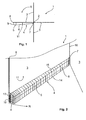
- FIG. 1 shows a rotating device 1 with the safety sensor 4 according to the invention.
- the rotating device 1 comprises four wings 3, the extending from a rotation axis 2 in the drawing up, down, left and right.
- the safety sensor 4 according to the invention is arranged in the direction of rotation R at the front of the shearing edge 5 of the blade 3, which is formed at the lower edge of the blade 3, and which moves near the ground on the wing 3 extending to the left.
- a clamping element 7 is arranged in front of the wing 3. From the clamping element 7 is up to the edge 8 of the wing 3, ie up to its front side, a band 6 spaced from the front surface 11 of the wing 3 stretched.
- the band 6 is held at the edge 8 of the wing 3, or at its front side, by a spacer 9, which is decisive for the spacing of the band 6 from the front surface 11 of the wing 3.
- the spacer 9 is pivotable, in this case represented by an arrow, in the direction of the axis of rotation 2, or in the direction of the clamping element 7.
- the spacer 9 pivots in the event of mechanical contact of the strip 6 with an occurring obstacle in the direction of the clamping element 7 or in the axis of rotation 2. This shortens the path of the band 6 between the spacer 9 and the clamping element 7, namely by a value which is calculated from the pivot angle and the length of the pivoted spacer 9.
- the spacer 9 is in a pivot angle to the wing 3 of 0 ° parallel to the wing 3 at. In this case, the path of the band 6 between the spacer 9 and the clamping element 7 is shortened by the length of the spacer 9.
- FIG. 2 shows a perspective view of the safety sensor 4 from FIG. 1 in a detailed view. From the front left in the viewing plane, the viewer looks at the edge 8 of the wing 3, or on its front side.
- a spacer 9 is arranged at the front over the shearing edge 5 at the edge 8 of the blade 3, which is mounted in the present case on an axis 13 extending parallel to the edge 8 of the blade 3.
- this axis 13 is spring-loaded by an elastic clamping element 10, for example by an axle-mounted spring.
- the tensioning force of the spacers 9 mounted on this axle 13 can be adjusted.
- the spacer 9 is designed so that it spaced between this and the rear right in the viewing plane in the axis of rotation 2 of the rotating device 1 clamping element 7 strained band 6 spaced from the front surface 11 of the wing 3 and this over a large area along the wing 3 in a three-dimensional shape forces.
- the band 6 has a parallel to the front surface 11 of the blade 3 end face 14 and an upward toward the front surface 11 of the wing 3 towards angled roof surface 15, which is the clamping element 7 out as a result of reducing the distance between the End face 14 of the band 6 and the front surface 11 of the wing 3 tapers.
- the clamping element 7 is mounted on an axis 16 arranged parallel to the axis of rotation 2 of the rotary element 1.
- the length of the clamping element 7 along the axis 16 in the present case corresponds to the height of the belt 6, which is calculated from the height of the end face 14 of the belt 6 and the height of the roof 15 of the belt 6.
- the tensioning element 7 is a tensioning roller on which the belt 6 can be rolled up. When the tape 6 is rolled up by the tensioning element 7, the tape is again brought from its positively driven three-dimensional shape into a two-dimensional shape.
Landscapes
- Engineering & Computer Science (AREA)
- Mechanical Engineering (AREA)
- Power-Operated Mechanisms For Wings (AREA)
- Extensible Doors And Revolving Doors (AREA)
Abstract
Description
- Die vorliegende Erfindung betrifft eine Dreheinrichtung mit mindestens zwei rotierenden Flügeln und einen Sicherheitssensor, wobei der Sicherheitssensor an einer in Drehrichtung (R) vorne und am Boden geführten Scherkante der Flügel angeordnet ist, und wobei der Sicherheitssensor bei einem mechanischen Kontakt mit einem Hindernis die Drehgeschwindigkeit der Dreheinrichtung verändert.
- Solche Dreheinrichtungen sind insbesondere in Karusselltüren hinlänglich bekannt. Neben manuell betätigbaren Karusselltüren sind auch solche bekannt, die mit einem elektromotorischen Antrieb ausgestattet sind. Dabei gibt es Konzepte, bei denen der elektromotorische Antrieb die gesamte oder auch nur einen Teil der für eine Drehbewegung der Karusselltür aufzubringende Antriebskraft aufbringt. Es sind auch elektromotorische Antriebe mit vollautomatischen, mikroprozessorgesteuerten Antriebssystemen bekannt.
- Die bekannten Karusselltüren weisen außen zwei feststehende Trommelwände auf, welche zwei Durchgänge besitzen, die in der Regel diametral gegenüberliegen. Innerhalb der Trommelwände befindet sich eine Dreheinrichtung mit einem zwei-, drei- oder vierflügeligen Drehteil mit einer im Zentrum stehenden Drehachse, von der direkt oder indirekt Türflügel ausgehen. Mittels eines elektromotorischen Antriebes wird diese Dreheinrichtung in Drehung versetzt, bzw. mittels des elektromotorischen Antriebes in der Drehung unterstützt. Die Türflügel rotieren bei der Drehung der Dreheinrichtung und zwar dergestalt, dass die nach außen gerichteten Enden, die auch als Stirnseiten der Türflügel bezeichnet werden, mit den Innenseiten der Trommelwände abschließen.
- Für das durch einen elektromotorischen Antrieb angetriebene Drehteil in einer Karusselltür ist je nach Einbausituation in der Regel eine aufwändige Sensorik für eine die Karusselltür passierende Person notwendig. Die Sensorik kann dabei Schaltmatten, Sensorleisten, Lichtvorhänge, Infrarot- und Radarmelder und Lichtschranken umfassen. Bleibt beispielsweise die Person im Drehteil der Karusselltür stehen oder kann aus welchem Grund auch immer nicht mit der Drehgeschwindigkeit der Karusselltür Schritt halten, muss bei Kontakt mit einem in Drehrichtung von hinten an die Person herangeführten Türflügel gewährleistet werden, dass die Drehgeschwindigkeit verringert wird, bzw. die Drehung des Drehteils abrupt unterbrochen wird. Dieses abrupte Haltemanöver im Notfall ist nicht einfach durchzuführen und ist zudem sehr materialbeanspruchend. Üblicher Weise sind bei den bekannten Karusselltüren mitdrehende Anwesenheitssensoren, sowie an den Scherkanten Sicherheitskontaktleisten aus Gummi verbaut, welche bei Deformation einen elektrischen Kontakt auslösen. Diese Sensoren sind extrem kostenintensiv. Zudem sind den Personen, die die Karusselltür passieren, der Erfassungsbereich der Sensoren und der Grund der Anwesenheitssensoren oftmals nicht bekannt. Dies führt regelmäßig dazu, dass die Karusselltür durch diese Personen ungewollt durch Auslösen der Sicherheitssensorik gestoppt wird bzw. deren Drehgeschwindigkeit verringert wird. Das ungewollte Stoppen und das Verringern der Drehgeschwindigkeit der Karusselltür wird oftmals als Defekt des Antriebes der Karusselltür gewertet, weshalb die Personen, die in einer Karusselltür vermeintlich zwangsgestoppt werden, im Extremfall unbeherrscht bzw. panisch reagieren. Zumindest aber sind die Personen, die durch einen vermeintlichen Zwangsstopp in der Karusselltür festgehalten werden, oftmals unzufrieden.
- Davon ausgehend liegt der vorliegenden Erfindung die Aufgabe zugrunde, einen preisgünstigen Sicherheitssensor zu schaffen, der eine einwandfreie Funktionsweise einer Dreheinrichtung einer Karusselltür unter Beibehaltung des sicherheitsrelevanten Aspektes gewährleistet, und der zudem von den Personen, die eine Dreheinrichtung einer Karusselltür passieren, wahrgenommen und als Sicherheitssensor erkannt wird.
- Diese Aufgabe wird ausgehend von einer Dreheinrichtung, umfassend mindestens zwei an einer Drehachse rotierende Flügel und einen Sicherheitssensor, wobei der Sicherheitssensor an einer in Drehrichtung (R) vorne und am Boden geführten Scherkante der Flügel angeordnet ist, und wobei der Sicherheitssensor bei einem mechanischen Kontakt mit einem Hindernis die Drehgeschwindigkeit der Dreheinrichtung verändert, gemäß dem Oberbegriff des Anspruchs 1 in Verbindung mit den kennzeichnenden Merkmalen gelöst. Vorteilhafte Weiterbildungen sind in den abhängigen Ansprüchen angegeben.
- Die Erfindung schließt die technische Lehre ein, dass der Sicherheitssensor wenigstens ein zumindest abschnittsweise nicht flexibles Band umfasst, welches im Bereich der Drehachse an einem Spannelement angeordnet ist, und welches an einem der Drehachse gegenüberliegenden Rand der Flügel und beabstandet zu dem Flügel angeordnet ist.
- Erfindungsgemäß umfasst der Sicherheitssensor ein zumindest abschnittsweise nicht flexibles Band, welches beispielsweise ein aus einem Geflecht, ein aus einer Folie oder ein aus einem anderen aufrollbaren Material hergestelltes Band sein kann. Dieses Band ist im Bereich der Drehachse der Dreheinrichtung an einem Spannelement angeordnet und wird von diesem beabstandet zu dem Flügel, beispielsweise einem Türflügel einer Karusselltür, bis zu dem der Drehachse der Dreheinrichtung gegenüberliegenden Rand des Flügels, also bis an die Stirnseite des Flügels geführt. Das bedeutet, dass das Band in Drehrichtung der Tür vorne an der Scherkante der Flügel über dessen gesamte Flügelbreite angeordnet ist. Sobald eine Person, die sich in der Dreheinrichtung befindet, das Band eindrückt, wird dessen Spannung verändert, wobei die Spannungsänderung über das Spannelement von einem Sensor, beispielsweise einem Schalter, einem Hallgeber oder einem Read-Kontakt erfasst wird. Auf diese Weise kann eine kostengünstige und als Sicherheitssensor voll funktionsfähige Sicherheitskontaktleiste bereitgestellt werden, die von Personen, die die Dreheinrichtung benutzen, als solche gesehen und von diesen Personen als Sensor wahrgenommen werden.
- Insbesondere vor dem Hintergrund, dass das Band vorzugsweise eine Höhe zwischen 15 cm und 30 cm aufweist, und besonders bevorzugt eine Höhe von 25 cm aufweist, kann es als Werbefläche dienen, bzw. durch Farbmarkierungen oder unterschiedliche Farben den Personen, die die Dreheinrichtung benutzen, in den Fokus gerückt werden. Natürlich kann das Band auch eine geringere Höhe als 15 cm aufweisen, bzw. kann dessen Höhe größer als 30 cm sein. Selbstverständlich ist es auch denkbar, ein aus einem Licht leitenden, Licht emittierenden oder Licht reflektierenden Material hergestelltes Band zwischen dem Spannelement und dem der Drehachse gegenüberliegenden Rand der Flügel anzuordnen.
- In vorteilhafter Weise ist das Band an dem der Drehachse gegenüberliegenden Rand des Flügels an einem Abstandshalter gehalten, der ein elastisches Element umfasst. Dabei ist der Abstandshalter vorzugsweise schwenkbeweglich an einer Achse im Bereich des Randes des Flügels am Flügel gehaltert, wobei ein elastisches Element in der Achse, beispielsweise eine Feder, eine Achsspannung erzeugt, die die Schwenkbeweglichkeit des Abstandshalters beeinflusst. Besonders bevorzugt ist dabei die Schwenkbeweglichkeit des Abstandshalters über eine Einstellung der Achsspannung über das federelastische Element veränderbar. Die Schwenkbeweglichkeit des Abstandshalters wird dabei bevorzugt so über die Einstellung des elastischen Elements in der Achse gewählt, dass ein Gleichgewicht zwischen der Zugkraft des im Drehbereich des Drehelements angeordneten Spannelements und der Achsspannung des Abstandshalters über das das Spannelement und Abstandshalter verbindende und verspannte Band besteht.
- Vorzugsweise ist der Abstandshalter bei Überwindung des Gleichgewichts der Zugkraft und der Achsspannung, nämlich bei mechanischer Druckausübung auf das Band durch ein Hindernis, welches auf das Band trifft, aus einer Ausgangsposition in Richtung der Drehachse verschwenkbar. Das bedeutet natürlich auch, dass bei Entlastung des Bandes und bei Gleichgewichtswiederherstellung zwischen der Zugkraft und der Achsspannung der Abstandshalter entgegen dieser Richtung wieder zurückschwenkbar in seine Ausgangsposition ist. Bei Überwindung des Gleichgewichts und durch Verschwenken des Abstandshalters in Richtung der Drehachse, verkürzt sich der Weg vom Spannelement zu dem Abstandshalter, nämlich um den Weg, der der Länge des Abstandshalters entspricht. Dies verursacht eine Spannungsminderung des den Abstandshalters und das Spannelement verbindende Band. In Folge dessen versucht das im Bereich der Drehachse angeordnete Spannelement dessen Gleichgewicht mit dem Abstandshalter über das Band wiederherzustellen, weshalb es die Spannung des Bandes wieder erhöht. Dies geschieht vorzugsweise durch ein Aufrollen des Bandes.
- Vorzugsweise ist das Spannelement als federbelastete Spannrolle ausgebildet. Dabei ist die Spannrolle in besonders bevorzugter Weise auf einer Achse gelagert, die zumindest abschnittsweise parallel zur Drehachse der Dreheinrichtung angeordnet ist. Dabei wird die Achse von einem federelastischen Element kraftbeaufschlagt. Durch das federelastische Element kann bevorzugt eine Vorspannung des Spannelements eingestellt werden. In vorteilhafter Weise ist die Länge des Spannelements entlang der Achse durch die Höhe des Bandes bestimmt. Die Länge des Spannelements kann aber auch zu der Höhe des Bandes variieren.
- Vorteilhafterweise rollt das Spannelement das Band bei einem mechanischen Kontakt mit einem Hindernis, welches sich in Drehbewegung vor dem Flügel der Dreheinrichtung befindet, zumindest abschnittsweise auf. Dadurch wird zum einen verhindert, dass sich das Band bei dessen Entspannung zwischen dem Scherrand und dem Boden, über den sich der Flügel der Dreheinrichtung bewegt, eingeklemmt wird, und zum anderen wird vorzugsweise das Aufrollen des Bandes, nämlich die Drehbewegung des Spannelements, von einem Sensor erfasst. Der Sensor gibt dabei in vorteilhafter Weise ein Signal an eine Steuerung weiter, über die die Drehgeschwindigkeit der Karusselltür verändert bzw. reguliert wird.
- Die Veränderung bzw. Regulierung der Drehgeschwindigkeit ist vorliegend so zu verstehen, dass die Drehgeschwindigkeit bei einem mechanischen Kontakt des Bandes mit einem Hindernis verringert wird. Dabei kann die Verringerung der Drehgeschwindigkeit bis zu einem Stopp, d. h. bis zu einem Stillstand der Dreheinrichtung erfolgen.
- In bevorzugter Weise eignet sich die Dreheinrichtung mit dem erfindungsgemäßen Sicherheitssensor für eine Karusselltür mit äußeren, feststehenden und zwei Durchgänge aufweisenden Trommelwänden sowie mit einer innerhalb der umgebenden Trommelwänden angeordneten Dreheinrichtung mit mindestens zwei rotierenden Türflügeln und einem Sicherheitssensor nach einem der vorhergehenden Ansprüche. Als Flügel der Dreheinrichtung sind dabei die mindestens zwei rotierenden Türflügel der Karusselltür zu verstehen. Natürlich kann der erfindungsgemäße Sicherheitssensor auch in Kombination mit bekannten Sensorsystemen, wie beispielsweise Anwesenheitssensoren, in einer Dreheinrichtung einer Karusselltür angeordnet sein.
- Bei bereits installierten Dreheinrichtungen einer Karusselltür bzw. bei bereits installierten Karusselltüren, lässt sich der erfindungsgemäße Sicherheitssensor, der vorliegend beispielsweise eine bekannte Sicherheitskontaktleiste ersetzt, nachträglich installieren, bzw. nachrüsten. Dabei wird im Bereich der Drehachse der Karusselltür an jedem Fensterflügel ein Spannelement und an dem der Drehachse gegenüberliegenden Rand des Fensterflügels ein Abstandshalter angeordnet. Der Abstandshalter und das Spannelement werden mit einem zumindest abschnittsweise nicht flexiblen Band verbunden und gegenseitig über das Band auf Spannung gebracht. Dabei sorgt ein am Abstandshalter angeordnetes Federelement, beispielsweise eine verstellbare Feder, für ein Gleichgewicht aus Zugkraft des Spannelements und Spannkraft des Abstandshalters.
- In vorteilhafter Weise kann der erfindungsgemäße Sicherheitssensor auch für gebogene Türblätter verwendet werden. Dabei ist in Bezug auf eine mögliche Verletzungsgefahr eine flexible Ausgestaltung des Abstandshalters notwendig. Natürlich ist bei der flexiblen Ausgestaltung der Abstandshalter darauf zu achten, dass die Funktionsweise des Sicherheitssensors nicht beeinträchtigt wird.
- Weitere, die Erfindung verbessernde Maßnahmen werden nachstehend mit der Beschreibung bevorzugter Ausführungsbeispiele der Erfindung anhand der Figuren näher dargestellt. Es zeigt:
- Fig. 1
- eine Draufsicht auf eine Dreheinrichtung mit einem erfindungsgemäßen Sicherheitssensor und
- Fig. 2
- eine perspektivische Ansicht des Sicherheitssensors aus
Figur 1 in einer Detailansicht. - In den unterschiedlichen Figuren sind gleiche Teile stets mit denselben Bezugszeichen versehen, weshalb diese in der Regel auch nur einmal beschrieben werden.
-
Figur 1 zeigt eine Dreheinrichtung 1 mit dem erfindungsgemäßen Sicherheitssensor 4. Die Dreheinrichtung 1 umfasst vier Flügel 3, die sich von einer Drehachse 2 in der Zeichnung nach oben, nach unten, nach links und nach rechts erstrecken. Beispielhaft ist an dem sich nach links erstreckenden Flügel 3 der erfindungsgemäße Sicherheitssensor 4 in Drehrichtung R vorne an der Scherkante 5 des Flügels 3 angeordnet, welche am unteren Rand des Flügels 3 ausgebildet ist, und welche sich bodennah bewegt. Im Bereich der Drehachse 2 der Dreheinrichtung 1 ist vor dem Flügel 3 ein Spannelement 7 angeordnet. Von dem Spannelement 7 aus ist bis zu dem Rand 8 des Flügels 3, also bis zu dessen Stirnseite, ein Band 6 beabstandet zu der vorderen Fläche 11 des Flügels 3 gespannt. Das Band 6 wird am Rand 8 des Flügels 3, bzw. an dessen Stirnseite, von einem Abstandshalter 9 gehalten, der maßgeblich für die Beabstandung des Bandes 6 von der vorderen Fläche 11 des Flügels 3 ist. Der Abstandshalter 9 ist dabei verschwenkbar, vorliegend durch einen Pfeil dargestellt, in Richtung der Drehachse 2, bzw. in Richtung des Spannelements 7. Dabei verschwenkt der Abstandshalter 9 bei einem mechanischen Kontakt des Bandes 6 mit einem auftretenden Hindernis in die Richtung des Spannelements 7 bzw. in der Drehachse 2. Dadurch verkürzt sich der Weg des Bandes 6 zwischen dem Abstandshalter 9 und dem Spannelement 7, und zwar um einen Wert, der sich aus dem Schwenkwinkel und der Länge des verschwenkten Abstandshalters 9 berechnet. Im Extremfall liegt der Abstandshalter 9 in einem Schwenkwinkel zu dem Flügel 3 von 0° parallel am Flügel 3 an. In diesem Fall verkürzt sich der Weg des Bandes 6 zwischen dem Abstandshalter 9 und dem Spannelement 7 um die Länge des Abstandshalters 9. -
Figur 2 zeigt eine perspektivische Ansicht des Sicherheitssensors 4 ausFigur 1 in einer Detailansicht. Von vorne links in der Betrachtungsebene schaut der Betrachter auf den Rand 8 des Flügels 3, bzw. auf dessen Stirnseite. In Drehrichtung R ist vorne über der Scherkante 5 am Rand 8 des Flügels 3 ein Abstandshalter 9 angeordnet, der vorliegend an einer sich parallel zum Rand 8 des Flügels 3 erstreckenden Achse 13 gelagert ist. Vorzugsweise ist diese Achse 13 durch ein elastisches Spannelement 10, beispielsweise durch eine achsgelagerte Feder federbelastbar. Durch das elastische Spannelement 10 kann dadurch die Spannkraft des an dieser Achse 13 gelagerten Abstandshalter 9 eingestellt werden. Vorliegend ist der Abstandshalter 9 so ausgestaltet, dass er das sich zwischen diesem und dem in der Betrachtungsebene hinten rechts im Bereich der Drehachse 2 der Dreheinrichtung 1 angeordneten Spannelement 7 verspannte Band 6 beabstandet zu der vorderen Fläche 11 des Flügels 3 und dieses über einen großen Bereich entlang des Flügels 3 in eine dreidimensionale Form zwingt. Dabei weist das Band 6 eine parallel zur vorderen Fläche 11 des Flügels 3 liegende Stirnfläche 14 und eine dazu nach oben hin zur vorderen Fläche 11 des Flügels 3 hin abgewinkelte Dachfläche 15 auf, die sich zum Spannelement 7 hin in Folge der Verringerung des Abstandes zwischen der Stirnfläche 14 des Bandes 6 und der vorderen Fläche 11 des Flügels 3 verjüngt. Das Spannelement 7 ist wie dargestellt auf einer sich parallel zur Drehachse 2 des Drehelements 1 angeordneten Achse 16 gelagert. Die Länge des Spannelements 7 entlang der Achse 16 entspricht vorliegend der Höhe des Bandes 6, welche sich aus der Höhe der Stirnfläche 14 des Bandes 6 und der Höhe des Daches 15 des Bandes 6 berechnet. Bevorzugt handelt es sich bei dem Spannelement 7 um eine Spannrolle, auf die das Band 6 aufrollbar ist. Beim Aufrollen des Bandes 6 durch das Spannelement 7 wird das Band wieder aus seiner zwangsgeführten dreidimensionalen Form in eine zweidimensionale Form gebracht. - Die Erfindung beschränkt sich in ihrer Ausführung nicht auf das vorhergehend angegebene bevorzugte Ausführungsbeispiel bzw. auf das vorhergehend angegebene Verfahren. Vielmehr ist eine Anzahl von Varianten denkbar, welche von der dargestellten Lösung auch bei grundsätzlich anders gearteten Ausführungen Gebrauch macht. Sämtliche aus den Ansprüchen, der Beschreibung oder den Zeichnungen hervorgehende Merkmale und/oder Vorteile, einschließlich konstruktiver Einzelheiten, räumliche Anordnungen und Verfahrensschritte, können sowohl für sich als auch in den verschiedensten Kombinationen erfindungswesentlich sein.
-
- 1
- Dreheinrichtung
- 2
- Drehachse
- 3
- Flügel
- 4
- Sicherheitssensor
- 5
- Scherkante
- 6
- Band
- 7
- Spannelement
- 8
- Rand des Flügels 3
- 9
- Abstandshalter
- 10
- elastisches Spannelement
- 11
- vordere Fläche des Flügels 3
- 13
- Achse zur Lagerung des Abstandshalters 9
- 14
- Stirnfläche Band 6
- 15
- Dachfläche Band 6
- 16
- Achse zur Lagerung des Spannelements 7
Claims (10)
- Dreheinrichtung (1), umfassend mindestens zwei an einer Drehachse (2) rotierende Flügel (3) und einen Sicherheitssensor (4), wobei der Sicherheitssensor (4) an einer in Drehrichtung (R) vorne und am Boden geführten Scherkante (5) der Flügel (3) angeordnet ist, und wobei der Sicherheitssensor (4) bei einem mechanischen Kontakt mit einem Hindernis eine Drehgeschwindigkeit der Dreheinrichtung (1) verändert, dadurch gekennzeichnet, dass der Sicherheitssensor (4) wenigstens ein zumindest abschnittsweise nicht flexibles Band (6) umfasst, welches im Bereich der Drehachse (2) an einem Spannelement (7) angeordnet ist, und welches an einem der Drehachse (2) gegenüberliegenden Rand (8) der Flügel (3) und beabstandet zu dem Flügel (3) angeordnet ist.
- Dreheinrichtung (1) nach Anspruch 1, dadurch gekennzeichnet, dass ein Abstandshalter (9), umfassend wenigstens ein elastisches Spannelement (10), welcher das Band (6) vom Rand (8) des Flügels (3) bis zu dem Spannelement (7) zumindest abschnittsweise beabstandet zu dem Flügel (3) hält.
- Dreheinrichtung (1) nach Anspruch 2, dadurch gekennzeichnet, dass der Abstandshalter (9) in Richtung der Drehachse (2) verschwenkbar ist.
- Dreheinrichtung (1) nach einem der vorhergehenden Ansprüche, dadurch gekennzeichnet, dass das Band (6) zwischen dem Abstandshalter (9) und dem Spannelement (7) beabstandet zur vorderen Fläche (11) des Flügels (3) spannbar ist.
- Dreheinrichtung (1) nach einem der vorhergehenden Ansprüche, dadurch gekennzeichnet, dass das Spannelement (7) eine federbelastete Spannrolle ist und/oder das elastische Spannelement (10) eine Feder ist.
- Dreheinrichtung (1) nach einem der vorhergehenden Ansprüche, dadurch gekennzeichnet, dass das Spannelement (7) das Band (6) bei einem mechanischen Kontakt mit einem auftretenden Hindernis zumindest abschnittsweise aufrollt.
- Dreheinrichtung (1) nach einem der vorhergehenden Ansprüche, dadurch gekennzeichnet, dass ein Sensor ein Aufrollen des Bandes (6) durch das Spannelement (7) erfasst.
- Dreheinrichtung (1) nach einem der vorhergehenden Ansprüche, dadurch gekennzeichnet, dass der Sensor bei Erfassung des Aufrollens des Bandes (6) durch das Spannelement (7) ein Signal an eine Steuerung weiterleitet, die die Drehgeschwindigkeit der Dreheinrichtung (2) reguliert.
- Karusselltür mit äußeren, feststehenden und zwei Durchgänge aufweisenden Trommelwänden sowie mit einer innerhalb der umgebenden Trommelwänden angeordneten Dreheinrichtung (2) mit mindestens zwei rotierenden Türflügeln (3) und einem Sicherheitssensor (6) nach einem der vorhergehenden Ansprüche.
- Verfahren zum Nachrüsten einer Dreheinrichtung (2), insbesondere einer Dreheinrichtung (2) einer Karusselltür, mit einem Sicherheitssensor (6), insbesondere nach einem der vorhergehenden Ansprüche, dadurch gekennzeichnet, dass im Bereich der Drehachse (2) der Dreheinrichtung (1) ein Spannelement (7) angeordnet wird, und dass am Rand eines Flügels (3) ein Abstandshalter (9) angeordnet wird, wobei zwischen dem Spannelement (7) und dem Abstandshalter (9) ein zumindest abschnittsweise nicht flexibles Band (6) zumindest abschnittsweise beabstandet zu dem Flügel (3) gespannt wird.
Applications Claiming Priority (1)
| Application Number | Priority Date | Filing Date | Title |
|---|---|---|---|
| DE102013107007.8A DE102013107007A1 (de) | 2013-07-03 | 2013-07-03 | Dreheinrichtung mit Sicherheitssensor |
Publications (2)
| Publication Number | Publication Date |
|---|---|
| EP2821580A1 true EP2821580A1 (de) | 2015-01-07 |
| EP2821580B1 EP2821580B1 (de) | 2017-07-12 |
Family
ID=50927872
Family Applications (1)
| Application Number | Title | Priority Date | Filing Date |
|---|---|---|---|
| EP14001849.0A Not-in-force EP2821580B1 (de) | 2013-07-03 | 2014-05-28 | Dreheinrichtung mit Sicherheitssensor |
Country Status (2)
| Country | Link |
|---|---|
| EP (1) | EP2821580B1 (de) |
| DE (1) | DE102013107007A1 (de) |
Families Citing this family (1)
| Publication number | Priority date | Publication date | Assignee | Title |
|---|---|---|---|---|
| DE102020117346A1 (de) * | 2020-07-01 | 2022-01-05 | Dormakaba Deutschland Gmbh | Karusselltür mit lichtsignalfunktion |
Citations (3)
| Publication number | Priority date | Publication date | Assignee | Title |
|---|---|---|---|---|
| JPH116362A (ja) * | 1997-06-18 | 1999-01-12 | Nabco Ltd | 自動回転ドア |
| JP2005068754A (ja) * | 2003-08-22 | 2005-03-17 | Matsushita Electric Ind Co Ltd | 自動回転ドア装置 |
| JP2009155869A (ja) * | 2007-12-26 | 2009-07-16 | Sanwa Shutter Corp | 回転ドア装置 |
-
2013
- 2013-07-03 DE DE102013107007.8A patent/DE102013107007A1/de not_active Withdrawn
-
2014
- 2014-05-28 EP EP14001849.0A patent/EP2821580B1/de not_active Not-in-force
Patent Citations (3)
| Publication number | Priority date | Publication date | Assignee | Title |
|---|---|---|---|---|
| JPH116362A (ja) * | 1997-06-18 | 1999-01-12 | Nabco Ltd | 自動回転ドア |
| JP2005068754A (ja) * | 2003-08-22 | 2005-03-17 | Matsushita Electric Ind Co Ltd | 自動回転ドア装置 |
| JP2009155869A (ja) * | 2007-12-26 | 2009-07-16 | Sanwa Shutter Corp | 回転ドア装置 |
Also Published As
| Publication number | Publication date |
|---|---|
| EP2821580B1 (de) | 2017-07-12 |
| DE102013107007A1 (de) | 2015-01-08 |
Similar Documents
| Publication | Publication Date | Title |
|---|---|---|
| WO2007036216A1 (de) | Sperrelement, insbesondere für eine durchgangssperre zur personendurchgangskontrolle | |
| EP2925947B1 (de) | Rolltor mit einem torblatt in gestalt eines flexiblen behangs | |
| EP1671006B1 (de) | Rolltor mit kollisionsschutz | |
| DE19881124B4 (de) | Mit Klemmschutzsystem versehener Fensterheber für Kraftfahrzeuge | |
| DE10122407B4 (de) | Mähvorrichtung zum Mähen eines Bereichs neben einem Tragmittel | |
| EP3660251B1 (de) | Schutzvorrichtung, insbesondere industrietor | |
| EP2821580B1 (de) | Dreheinrichtung mit Sicherheitssensor | |
| DE69603590T2 (de) | Hubtor mit sicherheitssystem | |
| WO2005108730A1 (de) | Karusselltür | |
| EP1936098B1 (de) | Automatische Türanlage | |
| EP2354415B1 (de) | Sektionaltor | |
| DE10109141C2 (de) | Vorrichtung zum Hemmen der öffnenden Schwenkbewegung einer Fahrzeugtüre | |
| DE202010010794U1 (de) | Torantriebsvorrichtung sowie damit versehene Toranlage | |
| DE19906562B4 (de) | Einklemmsicherung für Fensterheber von Fahrzeugen | |
| DE202012101497U1 (de) | Torantriebsset und Prüfkörper | |
| EP2402543B1 (de) | Rolltor und Verfahren zur Erfassung eines unerwünschten Lastzustands bei einem solchen Rolltor | |
| EP2216473A1 (de) | Schiebe-Falt-Laden | |
| DE102014221953A1 (de) | Sicherheitsanordnung für Schwenktore, Torflügel sowie Schwenktor und Verfahren zum Absichern eines Torflügels eines Schwenktores | |
| DE102016121312B4 (de) | Fensteranordnung | |
| DE102006033719B4 (de) | Rolltor mit einem zumindest abschnittsweise flexiblen Torblatt | |
| DE3817911A1 (de) | Schwenktuere fuer absperrungen in durchgangsanlagen | |
| DE102009022409B4 (de) | Lamellenvorhang | |
| DE20320336U1 (de) | Rolltor mit Kollisionsschutz | |
| DE102004053820B4 (de) | Sensoranordnung für automatische Türanlagen | |
| EP3088652B1 (de) | Betriebsstartverfahren für einen automatischen gebäudeabschluss, gebäudeabschlussantriebsvorrichtung zur verwendung in dem verfahren sowie automatischer gebäudeabschluss |
Legal Events
| Date | Code | Title | Description |
|---|---|---|---|
| PUAI | Public reference made under article 153(3) epc to a published international application that has entered the european phase |
Free format text: ORIGINAL CODE: 0009012 |
|
| 17P | Request for examination filed |
Effective date: 20140528 |
|
| AK | Designated contracting states |
Kind code of ref document: A1 Designated state(s): AL AT BE BG CH CY CZ DE DK EE ES FI FR GB GR HR HU IE IS IT LI LT LU LV MC MK MT NL NO PL PT RO RS SE SI SK SM TR |
|
| AX | Request for extension of the european patent |
Extension state: BA ME |
|
| R17P | Request for examination filed (corrected) |
Effective date: 20150625 |
|
| RBV | Designated contracting states (corrected) |
Designated state(s): AL AT BE BG CH CY CZ DE DK EE ES FI FR GB GR HR HU IE IS IT LI LT LU LV MC MK MT NL NO PL PT RO RS SE SI SK SM TR |
|
| 17Q | First examination report despatched |
Effective date: 20160809 |
|
| STAA | Information on the status of an ep patent application or granted ep patent |
Free format text: STATUS: EXAMINATION IS IN PROGRESS |
|
| RAP1 | Party data changed (applicant data changed or rights of an application transferred) |
Owner name: DORMAKABA DEUTSCHLAND GMBH |
|
| REG | Reference to a national code |
Ref country code: DE Ref legal event code: R079 Ref document number: 502014004514 Country of ref document: DE Free format text: PREVIOUS MAIN CLASS: E05F0015000000 Ipc: E05F0015480000 |
|
| GRAP | Despatch of communication of intention to grant a patent |
Free format text: ORIGINAL CODE: EPIDOSNIGR1 |
|
| STAA | Information on the status of an ep patent application or granted ep patent |
Free format text: STATUS: GRANT OF PATENT IS INTENDED |
|
| RIC1 | Information provided on ipc code assigned before grant |
Ipc: E05F 15/614 20150101ALN20170124BHEP Ipc: E05F 15/608 20150101ALI20170124BHEP Ipc: E05F 15/48 20150101AFI20170124BHEP |
|
| RIC1 | Information provided on ipc code assigned before grant |
Ipc: E05F 15/48 20150101AFI20170215BHEP Ipc: E05F 15/614 20150101ALN20170215BHEP Ipc: E05F 15/608 20150101ALI20170215BHEP |
|
| INTG | Intention to grant announced |
Effective date: 20170228 |
|
| GRAS | Grant fee paid |
Free format text: ORIGINAL CODE: EPIDOSNIGR3 |
|
| GRAA | (expected) grant |
Free format text: ORIGINAL CODE: 0009210 |
|
| STAA | Information on the status of an ep patent application or granted ep patent |
Free format text: STATUS: THE PATENT HAS BEEN GRANTED |
|
| AK | Designated contracting states |
Kind code of ref document: B1 Designated state(s): AL AT BE BG CH CY CZ DE DK EE ES FI FR GB GR HR HU IE IS IT LI LT LU LV MC MK MT NL NO PL PT RO RS SE SI SK SM TR |
|
| REG | Reference to a national code |
Ref country code: GB Ref legal event code: FG4D Free format text: NOT ENGLISH |
|
| REG | Reference to a national code |
Ref country code: CH Ref legal event code: EP |
|
| REG | Reference to a national code |
Ref country code: AT Ref legal event code: REF Ref document number: 908512 Country of ref document: AT Kind code of ref document: T Effective date: 20170715 |
|
| REG | Reference to a national code |
Ref country code: IE Ref legal event code: FG4D Free format text: LANGUAGE OF EP DOCUMENT: GERMAN |
|
| REG | Reference to a national code |
Ref country code: DE Ref legal event code: R096 Ref document number: 502014004514 Country of ref document: DE |
|
| REG | Reference to a national code |
Ref country code: NL Ref legal event code: MP Effective date: 20170712 |
|
| REG | Reference to a national code |
Ref country code: LT Ref legal event code: MG4D |
|
| PG25 | Lapsed in a contracting state [announced via postgrant information from national office to epo] |
Ref country code: SE Free format text: LAPSE BECAUSE OF FAILURE TO SUBMIT A TRANSLATION OF THE DESCRIPTION OR TO PAY THE FEE WITHIN THE PRESCRIBED TIME-LIMIT Effective date: 20170712 Ref country code: FI Free format text: LAPSE BECAUSE OF FAILURE TO SUBMIT A TRANSLATION OF THE DESCRIPTION OR TO PAY THE FEE WITHIN THE PRESCRIBED TIME-LIMIT Effective date: 20170712 Ref country code: LT Free format text: LAPSE BECAUSE OF FAILURE TO SUBMIT A TRANSLATION OF THE DESCRIPTION OR TO PAY THE FEE WITHIN THE PRESCRIBED TIME-LIMIT Effective date: 20170712 Ref country code: HR Free format text: LAPSE BECAUSE OF FAILURE TO SUBMIT A TRANSLATION OF THE DESCRIPTION OR TO PAY THE FEE WITHIN THE PRESCRIBED TIME-LIMIT Effective date: 20170712 Ref country code: NL Free format text: LAPSE BECAUSE OF FAILURE TO SUBMIT A TRANSLATION OF THE DESCRIPTION OR TO PAY THE FEE WITHIN THE PRESCRIBED TIME-LIMIT Effective date: 20170712 Ref country code: NO Free format text: LAPSE BECAUSE OF FAILURE TO SUBMIT A TRANSLATION OF THE DESCRIPTION OR TO PAY THE FEE WITHIN THE PRESCRIBED TIME-LIMIT Effective date: 20171012 |
|
| PG25 | Lapsed in a contracting state [announced via postgrant information from national office to epo] |
Ref country code: LV Free format text: LAPSE BECAUSE OF FAILURE TO SUBMIT A TRANSLATION OF THE DESCRIPTION OR TO PAY THE FEE WITHIN THE PRESCRIBED TIME-LIMIT Effective date: 20170712 Ref country code: IS Free format text: LAPSE BECAUSE OF FAILURE TO SUBMIT A TRANSLATION OF THE DESCRIPTION OR TO PAY THE FEE WITHIN THE PRESCRIBED TIME-LIMIT Effective date: 20171112 Ref country code: RS Free format text: LAPSE BECAUSE OF FAILURE TO SUBMIT A TRANSLATION OF THE DESCRIPTION OR TO PAY THE FEE WITHIN THE PRESCRIBED TIME-LIMIT Effective date: 20170712 Ref country code: PL Free format text: LAPSE BECAUSE OF FAILURE TO SUBMIT A TRANSLATION OF THE DESCRIPTION OR TO PAY THE FEE WITHIN THE PRESCRIBED TIME-LIMIT Effective date: 20170712 Ref country code: BG Free format text: LAPSE BECAUSE OF FAILURE TO SUBMIT A TRANSLATION OF THE DESCRIPTION OR TO PAY THE FEE WITHIN THE PRESCRIBED TIME-LIMIT Effective date: 20171012 Ref country code: GR Free format text: LAPSE BECAUSE OF FAILURE TO SUBMIT A TRANSLATION OF THE DESCRIPTION OR TO PAY THE FEE WITHIN THE PRESCRIBED TIME-LIMIT Effective date: 20171013 Ref country code: ES Free format text: LAPSE BECAUSE OF FAILURE TO SUBMIT A TRANSLATION OF THE DESCRIPTION OR TO PAY THE FEE WITHIN THE PRESCRIBED TIME-LIMIT Effective date: 20170712 |
|
| REG | Reference to a national code |
Ref country code: DE Ref legal event code: R097 Ref document number: 502014004514 Country of ref document: DE |
|
| PG25 | Lapsed in a contracting state [announced via postgrant information from national office to epo] |
Ref country code: DK Free format text: LAPSE BECAUSE OF FAILURE TO SUBMIT A TRANSLATION OF THE DESCRIPTION OR TO PAY THE FEE WITHIN THE PRESCRIBED TIME-LIMIT Effective date: 20170712 Ref country code: RO Free format text: LAPSE BECAUSE OF FAILURE TO SUBMIT A TRANSLATION OF THE DESCRIPTION OR TO PAY THE FEE WITHIN THE PRESCRIBED TIME-LIMIT Effective date: 20170712 Ref country code: CZ Free format text: LAPSE BECAUSE OF FAILURE TO SUBMIT A TRANSLATION OF THE DESCRIPTION OR TO PAY THE FEE WITHIN THE PRESCRIBED TIME-LIMIT Effective date: 20170712 |
|
| PLBE | No opposition filed within time limit |
Free format text: ORIGINAL CODE: 0009261 |
|
| STAA | Information on the status of an ep patent application or granted ep patent |
Free format text: STATUS: NO OPPOSITION FILED WITHIN TIME LIMIT |
|
| PG25 | Lapsed in a contracting state [announced via postgrant information from national office to epo] |
Ref country code: SM Free format text: LAPSE BECAUSE OF FAILURE TO SUBMIT A TRANSLATION OF THE DESCRIPTION OR TO PAY THE FEE WITHIN THE PRESCRIBED TIME-LIMIT Effective date: 20170712 Ref country code: SK Free format text: LAPSE BECAUSE OF FAILURE TO SUBMIT A TRANSLATION OF THE DESCRIPTION OR TO PAY THE FEE WITHIN THE PRESCRIBED TIME-LIMIT Effective date: 20170712 Ref country code: IT Free format text: LAPSE BECAUSE OF FAILURE TO SUBMIT A TRANSLATION OF THE DESCRIPTION OR TO PAY THE FEE WITHIN THE PRESCRIBED TIME-LIMIT Effective date: 20170712 Ref country code: EE Free format text: LAPSE BECAUSE OF FAILURE TO SUBMIT A TRANSLATION OF THE DESCRIPTION OR TO PAY THE FEE WITHIN THE PRESCRIBED TIME-LIMIT Effective date: 20170712 |
|
| 26N | No opposition filed |
Effective date: 20180413 |
|
| PG25 | Lapsed in a contracting state [announced via postgrant information from national office to epo] |
Ref country code: SI Free format text: LAPSE BECAUSE OF FAILURE TO SUBMIT A TRANSLATION OF THE DESCRIPTION OR TO PAY THE FEE WITHIN THE PRESCRIBED TIME-LIMIT Effective date: 20170712 |
|
| PG25 | Lapsed in a contracting state [announced via postgrant information from national office to epo] |
Ref country code: MT Free format text: LAPSE BECAUSE OF FAILURE TO SUBMIT A TRANSLATION OF THE DESCRIPTION OR TO PAY THE FEE WITHIN THE PRESCRIBED TIME-LIMIT Effective date: 20170712 |
|
| REG | Reference to a national code |
Ref country code: DE Ref legal event code: R119 Ref document number: 502014004514 Country of ref document: DE |
|
| REG | Reference to a national code |
Ref country code: CH Ref legal event code: PL |
|
| GBPC | Gb: european patent ceased through non-payment of renewal fee |
Effective date: 20180528 |
|
| REG | Reference to a national code |
Ref country code: BE Ref legal event code: MM Effective date: 20180531 |
|
| PG25 | Lapsed in a contracting state [announced via postgrant information from national office to epo] |
Ref country code: MC Free format text: LAPSE BECAUSE OF FAILURE TO SUBMIT A TRANSLATION OF THE DESCRIPTION OR TO PAY THE FEE WITHIN THE PRESCRIBED TIME-LIMIT Effective date: 20170712 |
|
| REG | Reference to a national code |
Ref country code: IE Ref legal event code: MM4A |
|
| PG25 | Lapsed in a contracting state [announced via postgrant information from national office to epo] |
Ref country code: CH Free format text: LAPSE BECAUSE OF NON-PAYMENT OF DUE FEES Effective date: 20180531 Ref country code: LI Free format text: LAPSE BECAUSE OF NON-PAYMENT OF DUE FEES Effective date: 20180531 |
|
| PG25 | Lapsed in a contracting state [announced via postgrant information from national office to epo] |
Ref country code: LU Free format text: LAPSE BECAUSE OF NON-PAYMENT OF DUE FEES Effective date: 20180528 |
|
| PG25 | Lapsed in a contracting state [announced via postgrant information from national office to epo] |
Ref country code: IE Free format text: LAPSE BECAUSE OF NON-PAYMENT OF DUE FEES Effective date: 20180528 Ref country code: DE Free format text: LAPSE BECAUSE OF NON-PAYMENT OF DUE FEES Effective date: 20181201 Ref country code: GB Free format text: LAPSE BECAUSE OF NON-PAYMENT OF DUE FEES Effective date: 20180528 Ref country code: FR Free format text: LAPSE BECAUSE OF NON-PAYMENT OF DUE FEES Effective date: 20180531 |
|
| PG25 | Lapsed in a contracting state [announced via postgrant information from national office to epo] |
Ref country code: BE Free format text: LAPSE BECAUSE OF NON-PAYMENT OF DUE FEES Effective date: 20180531 |
|
| PG25 | Lapsed in a contracting state [announced via postgrant information from national office to epo] |
Ref country code: TR Free format text: LAPSE BECAUSE OF FAILURE TO SUBMIT A TRANSLATION OF THE DESCRIPTION OR TO PAY THE FEE WITHIN THE PRESCRIBED TIME-LIMIT Effective date: 20170712 |
|
| PG25 | Lapsed in a contracting state [announced via postgrant information from national office to epo] |
Ref country code: PT Free format text: LAPSE BECAUSE OF FAILURE TO SUBMIT A TRANSLATION OF THE DESCRIPTION OR TO PAY THE FEE WITHIN THE PRESCRIBED TIME-LIMIT Effective date: 20170712 Ref country code: HU Free format text: LAPSE BECAUSE OF FAILURE TO SUBMIT A TRANSLATION OF THE DESCRIPTION OR TO PAY THE FEE WITHIN THE PRESCRIBED TIME-LIMIT; INVALID AB INITIO Effective date: 20140528 |
|
| PG25 | Lapsed in a contracting state [announced via postgrant information from national office to epo] |
Ref country code: MK Free format text: LAPSE BECAUSE OF NON-PAYMENT OF DUE FEES Effective date: 20170712 Ref country code: CY Free format text: LAPSE BECAUSE OF FAILURE TO SUBMIT A TRANSLATION OF THE DESCRIPTION OR TO PAY THE FEE WITHIN THE PRESCRIBED TIME-LIMIT Effective date: 20170712 |
|
| PG25 | Lapsed in a contracting state [announced via postgrant information from national office to epo] |
Ref country code: AL Free format text: LAPSE BECAUSE OF FAILURE TO SUBMIT A TRANSLATION OF THE DESCRIPTION OR TO PAY THE FEE WITHIN THE PRESCRIBED TIME-LIMIT Effective date: 20170712 |
|
| REG | Reference to a national code |
Ref country code: AT Ref legal event code: MM01 Ref document number: 908512 Country of ref document: AT Kind code of ref document: T Effective date: 20190528 |
|
| PG25 | Lapsed in a contracting state [announced via postgrant information from national office to epo] |
Ref country code: AT Free format text: LAPSE BECAUSE OF NON-PAYMENT OF DUE FEES Effective date: 20190528 |