EP2820719B1 - Steckverbinder - Google Patents
Steckverbinder Download PDFInfo
- Publication number
- EP2820719B1 EP2820719B1 EP13712495.4A EP13712495A EP2820719B1 EP 2820719 B1 EP2820719 B1 EP 2820719B1 EP 13712495 A EP13712495 A EP 13712495A EP 2820719 B1 EP2820719 B1 EP 2820719B1
- Authority
- EP
- European Patent Office
- Prior art keywords
- plug
- socket
- locking device
- locking
- plug connector
- Prior art date
- Legal status (The legal status is an assumption and is not a legal conclusion. Google has not performed a legal analysis and makes no representation as to the accuracy of the status listed.)
- Not-in-force
Links
Images

Classifications
-
- B—PERFORMING OPERATIONS; TRANSPORTING
- B60—VEHICLES IN GENERAL
- B60L—PROPULSION OF ELECTRICALLY-PROPELLED VEHICLES; SUPPLYING ELECTRIC POWER FOR AUXILIARY EQUIPMENT OF ELECTRICALLY-PROPELLED VEHICLES; ELECTRODYNAMIC BRAKE SYSTEMS FOR VEHICLES IN GENERAL; MAGNETIC SUSPENSION OR LEVITATION FOR VEHICLES; MONITORING OPERATING VARIABLES OF ELECTRICALLY-PROPELLED VEHICLES; ELECTRIC SAFETY DEVICES FOR ELECTRICALLY-PROPELLED VEHICLES
- B60L53/00—Methods of charging batteries, specially adapted for electric vehicles; Charging stations or on-board charging equipment therefor; Exchange of energy storage elements in electric vehicles
- B60L53/10—Methods of charging batteries, specially adapted for electric vehicles; Charging stations or on-board charging equipment therefor; Exchange of energy storage elements in electric vehicles characterised by the energy transfer between the charging station and the vehicle
- B60L53/14—Conductive energy transfer
- B60L53/16—Connectors, e.g. plugs or sockets, specially adapted for charging electric vehicles
-
- H—ELECTRICITY
- H01—ELECTRIC ELEMENTS
- H01R—ELECTRICALLY-CONDUCTIVE CONNECTIONS; STRUCTURAL ASSOCIATIONS OF A PLURALITY OF MUTUALLY-INSULATED ELECTRICAL CONNECTING ELEMENTS; COUPLING DEVICES; CURRENT COLLECTORS
- H01R13/00—Details of coupling devices of the kinds covered by groups H01R12/70 or H01R24/00 - H01R33/00
- H01R13/46—Bases; Cases
- H01R13/502—Bases; Cases composed of different pieces
-
- H—ELECTRICITY
- H01—ELECTRIC ELEMENTS
- H01R—ELECTRICALLY-CONDUCTIVE CONNECTIONS; STRUCTURAL ASSOCIATIONS OF A PLURALITY OF MUTUALLY-INSULATED ELECTRICAL CONNECTING ELEMENTS; COUPLING DEVICES; CURRENT COLLECTORS
- H01R13/00—Details of coupling devices of the kinds covered by groups H01R12/70 or H01R24/00 - H01R33/00
- H01R13/62—Means for facilitating engagement or disengagement of coupling parts or for holding them in engagement
-
- H—ELECTRICITY
- H01—ELECTRIC ELEMENTS
- H01R—ELECTRICALLY-CONDUCTIVE CONNECTIONS; STRUCTURAL ASSOCIATIONS OF A PLURALITY OF MUTUALLY-INSULATED ELECTRICAL CONNECTING ELEMENTS; COUPLING DEVICES; CURRENT COLLECTORS
- H01R13/00—Details of coupling devices of the kinds covered by groups H01R12/70 or H01R24/00 - H01R33/00
- H01R13/62—Means for facilitating engagement or disengagement of coupling parts or for holding them in engagement
- H01R13/629—Additional means for facilitating engagement or disengagement of coupling parts, e.g. aligning or guiding means, levers, gas pressure electrical locking indicators, manufacturing tolerances
-
- H—ELECTRICITY
- H01—ELECTRIC ELEMENTS
- H01R—ELECTRICALLY-CONDUCTIVE CONNECTIONS; STRUCTURAL ASSOCIATIONS OF A PLURALITY OF MUTUALLY-INSULATED ELECTRICAL CONNECTING ELEMENTS; COUPLING DEVICES; CURRENT COLLECTORS
- H01R13/00—Details of coupling devices of the kinds covered by groups H01R12/70 or H01R24/00 - H01R33/00
- H01R13/62—Means for facilitating engagement or disengagement of coupling parts or for holding them in engagement
- H01R13/639—Additional means for holding or locking coupling parts together, after engagement, e.g. separate keylock, retainer strap
- H01R13/6397—Additional means for holding or locking coupling parts together, after engagement, e.g. separate keylock, retainer strap with means for preventing unauthorised use
-
- H—ELECTRICITY
- H01—ELECTRIC ELEMENTS
- H01R—ELECTRICALLY-CONDUCTIVE CONNECTIONS; STRUCTURAL ASSOCIATIONS OF A PLURALITY OF MUTUALLY-INSULATED ELECTRICAL CONNECTING ELEMENTS; COUPLING DEVICES; CURRENT COLLECTORS
- H01R13/00—Details of coupling devices of the kinds covered by groups H01R12/70 or H01R24/00 - H01R33/00
- H01R13/73—Means for mounting coupling parts to apparatus or structures, e.g. to a wall
-
- B—PERFORMING OPERATIONS; TRANSPORTING
- B60—VEHICLES IN GENERAL
- B60L—PROPULSION OF ELECTRICALLY-PROPELLED VEHICLES; SUPPLYING ELECTRIC POWER FOR AUXILIARY EQUIPMENT OF ELECTRICALLY-PROPELLED VEHICLES; ELECTRODYNAMIC BRAKE SYSTEMS FOR VEHICLES IN GENERAL; MAGNETIC SUSPENSION OR LEVITATION FOR VEHICLES; MONITORING OPERATING VARIABLES OF ELECTRICALLY-PROPELLED VEHICLES; ELECTRIC SAFETY DEVICES FOR ELECTRICALLY-PROPELLED VEHICLES
- B60L2270/00—Problem solutions or means not otherwise provided for
- B60L2270/30—Preventing theft during charging
- B60L2270/32—Preventing theft during charging of electricity
-
- B—PERFORMING OPERATIONS; TRANSPORTING
- B60—VEHICLES IN GENERAL
- B60L—PROPULSION OF ELECTRICALLY-PROPELLED VEHICLES; SUPPLYING ELECTRIC POWER FOR AUXILIARY EQUIPMENT OF ELECTRICALLY-PROPELLED VEHICLES; ELECTRODYNAMIC BRAKE SYSTEMS FOR VEHICLES IN GENERAL; MAGNETIC SUSPENSION OR LEVITATION FOR VEHICLES; MONITORING OPERATING VARIABLES OF ELECTRICALLY-PROPELLED VEHICLES; ELECTRIC SAFETY DEVICES FOR ELECTRICALLY-PROPELLED VEHICLES
- B60L2270/00—Problem solutions or means not otherwise provided for
- B60L2270/30—Preventing theft during charging
- B60L2270/34—Preventing theft during charging of parts
-
- H—ELECTRICITY
- H01—ELECTRIC ELEMENTS
- H01R—ELECTRICALLY-CONDUCTIVE CONNECTIONS; STRUCTURAL ASSOCIATIONS OF A PLURALITY OF MUTUALLY-INSULATED ELECTRICAL CONNECTING ELEMENTS; COUPLING DEVICES; CURRENT COLLECTORS
- H01R2201/00—Connectors or connections adapted for particular applications
- H01R2201/26—Connectors or connections adapted for particular applications for vehicles
-
- Y—GENERAL TAGGING OF NEW TECHNOLOGICAL DEVELOPMENTS; GENERAL TAGGING OF CROSS-SECTIONAL TECHNOLOGIES SPANNING OVER SEVERAL SECTIONS OF THE IPC; TECHNICAL SUBJECTS COVERED BY FORMER USPC CROSS-REFERENCE ART COLLECTIONS [XRACs] AND DIGESTS
- Y02—TECHNOLOGIES OR APPLICATIONS FOR MITIGATION OR ADAPTATION AGAINST CLIMATE CHANGE
- Y02T—CLIMATE CHANGE MITIGATION TECHNOLOGIES RELATED TO TRANSPORTATION
- Y02T10/00—Road transport of goods or passengers
- Y02T10/60—Other road transportation technologies with climate change mitigation effect
- Y02T10/70—Energy storage systems for electromobility, e.g. batteries
-
- Y—GENERAL TAGGING OF NEW TECHNOLOGICAL DEVELOPMENTS; GENERAL TAGGING OF CROSS-SECTIONAL TECHNOLOGIES SPANNING OVER SEVERAL SECTIONS OF THE IPC; TECHNICAL SUBJECTS COVERED BY FORMER USPC CROSS-REFERENCE ART COLLECTIONS [XRACs] AND DIGESTS
- Y02—TECHNOLOGIES OR APPLICATIONS FOR MITIGATION OR ADAPTATION AGAINST CLIMATE CHANGE
- Y02T—CLIMATE CHANGE MITIGATION TECHNOLOGIES RELATED TO TRANSPORTATION
- Y02T10/00—Road transport of goods or passengers
- Y02T10/60—Other road transportation technologies with climate change mitigation effect
- Y02T10/7072—Electromobility specific charging systems or methods for batteries, ultracapacitors, supercapacitors or double-layer capacitors
-
- Y—GENERAL TAGGING OF NEW TECHNOLOGICAL DEVELOPMENTS; GENERAL TAGGING OF CROSS-SECTIONAL TECHNOLOGIES SPANNING OVER SEVERAL SECTIONS OF THE IPC; TECHNICAL SUBJECTS COVERED BY FORMER USPC CROSS-REFERENCE ART COLLECTIONS [XRACs] AND DIGESTS
- Y02—TECHNOLOGIES OR APPLICATIONS FOR MITIGATION OR ADAPTATION AGAINST CLIMATE CHANGE
- Y02T—CLIMATE CHANGE MITIGATION TECHNOLOGIES RELATED TO TRANSPORTATION
- Y02T90/00—Enabling technologies or technologies with a potential or indirect contribution to GHG emissions mitigation
- Y02T90/10—Technologies relating to charging of electric vehicles
- Y02T90/14—Plug-in electric vehicles
Definitions
- the invention relates to a connector for electrically connecting an electric vehicle to a charging device, with a plug or a socket and an electrically driven locking device, wherein the plug or the socket for establishing an electrical connection to a second socket or a second plug of a second Electric vehicle or the charging device associated connector is configured.
- electrical interlock connectors are known and normatively provided to transfer electrical energy from the charger to charge a vehicle accumulator provided in the electric vehicle.
- a device plug can be provided on the charging device and / or on the electric vehicle, so that an electrical connection between the charging device and the electric vehicle can be produced by means of a connecting cable which has a cable plug corresponding to the device plug at both ends.
- the device connector and the cable connector can be designed as a plug or socket, the cable connector often as a plug, so with male contacts, and the device connector is often designed as a socket, so with female contacts.
- this electrical lock can provide a mechanical retraction of a cylindrical pin perpendicular to the direction of insertion of the fully plugged onto the plug connector, wherein by the cylindrical pin of the device connector and the cable connector in the radial direction can be penetrated via corresponding holes or contours, so that when locking a positive connection in the axial direction is generated.
- a manual release of the connected connector is prevented so that due to security aspects under electrical load standing connector can not be separated from each other or not fully performed charging of the vehicle battery is not interrupted.
- the drive of the cylinder pin is electromechanical, for example via solenoids or actuators with upstream mechanics.
- DE 20 2010 014351 U1 describes a mounted socket, at least comprising a sliding latch for locking a plugged into a plug receptacle of the extension socket connector and a servomotor, based on the extension socket, in a first mounting position can be mounted, wherein the servomotor is coupled in this directly to the latch.
- a device plug is inserted into the opening of a wall, such as an electric vehicle or a charging device, this often has to be done from the back of the wall, since the drive of the cylinder pin, especially if the cylindrical pin is inserted perpendicular to the plug-in direction of the connector, laterally protruding from the connector so that passage of the connector including driving the cylinder pin from the front of the wall through the opening is impossible.
- This means that a subsequent mounting of such a device plug, especially if no back attach the appliance plug to the wall due to limited space is possible in almost all Cases excluded. Therefore, it is the object of the invention to provide a connector for electrically connecting an electric vehicle with an electromechanically operated cylinder pin for locking a male-female pair, which is also subsequently mounted in a wall and in tight spaces.
- the object of the invention is achieved by a connector for electrically connecting an electric vehicle to a charging device, with a plug or a socket and an electromechanically driven locking device, wherein the plug or the socket for establishing an electrical connection to a second socket or a second connector of a second the electric vehicle or the charging device associated connector is configured, the locking device is designed to be movable axially to the plugging direction of the plug or the socket for mechanically locking and / or unlocking an interconnected male-female pair, and the locking device and / or the plug or the socket has a centering device designed in such a way that the locking device is releasably securable to the plug or to the socket in a position predetermined by the centering device.
- the connector is constructed in two parts, namely on the one hand the plug or the socket and on the other hand has the locking direction, wherein the locking direction on the plug or on the socket is releasably fastened. So this means that the connector also subsequently under difficult light and / or space in an opening of a wall an electric vehicle and / or a charging device can be used, for example, in a first step, the plug or the socket from the "outside" of the wall is inserted into the opening and then in a second step, the locking device from the "inside” of the wall the plug already inserted into the wall or on the socket can be fastened.
- the assembly is substantially simplified.
- the locking direction which is designed to be movable axially to the plug-in direction of the plug or the socket for mechanically locking a male-female pair
- due to the centering device comes to rest at a predetermined position on the plug or on the socket
- a cylindrical pin for mechanical locking in a contour of the plug or the socket can move axially to the direction of insertion of the male-female pair.
- the plug and / or the socket can be designed as any known from the prior art means for establishing an electrical connection between the connectors, such as Cable plug and / or device plug.
- both the plug and the socket have a plurality of electrical contacts, wherein the plug with male contacts and the socket with corresponding female contacts is particularly preferably designed.
- the connector can be used in conjunction with any of the known in the art electric vehicle and any charging device.
- the locking means can, as will be explained in more detail below, be designed, for example, as a cylindrical pin or as a bolt, wherein the cylinder pin or bolt axially to the insertion direction of the plug or the socket for mechanically locking and / or unlocking a connected plug socket Pair is designed movable.
- the plug and the socket have a respective contour or opening corresponding to the locking device, so that the locking device in its closed position preferably penetrates both respective contours or openings of the plug and the socket, thereby providing a mechanical locking of the interconnected plug connector. Jacks pair done. Accordingly, the locking device in its open position is not engaged with the aforementioned contour or opening of the second socket or of the second plug, so that the second socket or the second plug is removable from the plug or the socket.
- the centering device for example via a contour provided on the locking device with correspondingly provided on the plug or on the socket Counter contour, as further explained in detail below.
- the predetermined position preferably forms at least one positive connection in the radial direction to the plugging direction of the plug or the socket, especially preferably also forms an axial positive connection axially to the plug-in direction of the plug or the socket, most preferably in the direction of the second socket or the second plug, so preferably in "stripping" of a plug from a corresponding socket.
- the centering device is configured such that by attaching the locking device to the plug or to the socket by means of a first movement of the locking device in the radial direction to the plug-in direction of the plug or the socket and by means of a second movement in the axial direction to the plug-in direction of the plug or the socket, the predetermined position is reached.
- the centering device is preferably designed such that when approaching the locking device "from behind” to the plug or to the socket and subsequent “lowering" of the locking device, ie by the first movement in the radial direction, and following “after front sliding ", ie by the second movement in the axial direction, the predetermined position can be reached, in which the locking device is positively connected to the plug or the socket or the Locking device is positively secured to the plug or to the socket.
- the locking device can be attached in a particularly simple manner even in unfavorable light and / or difficult and cramped space on the plug or on the socket, so that for locking an interconnected male-female pair, the locking device in the predetermined or defined position can be moved axially to the direction of insertion of the plug or the socket.
- the locking device can be configured as desired, wherein very particularly preferably the locking device is designed as a bolt or as a cylindrical pin.
- the plug or the socket has an opening for insertion of the bolt, the opening and the bolt have a substantially equal diameter and the bolt in the predetermined position so relative to the plug or is arranged to the socket, that the bolt for mechanically locking an interconnected male-female pair is inserted axially to the direction of insertion of the plug or the socket in the opening.
- the plug connector has a drive device for the locking device, wherein the drive device comprises the locking device, the centering device is configured in two parts on the drive device and on the plug or on the socket and provided on the drive device first part of Centering device has a semicircular, in the axial direction to the plug-in direction of the plug or the sleeve extending projection and provided on the plug or on the socket second part of the centering device has a semicircular extending groove for positive reception of the projection.
- the first part of the centering device may have a contour and the second part of the centering device may have a counter contour for the positive reception of the contour.
- the centering device is arranged with a first part on the drive device and is arranged with a second part on the plug or on the socket, so that the first part and the second part of the centering device cooperate in such a way in that the locking device and the plug or the socket assume the predetermined position by the joining together of the drive device or the locking device with the plug or the socket.
- the drive device has a fastening means for fixing the drive device attached to the plug or to the socket.
- the fastening means is designed as a screw, for example as a self-tapping screw which may be pre-mounted on the drive means, so that after assembly of the drive means with the plug or the socket and after reaching the predefined position by the fastening means a fixation, preferably a permanent fixation, the drive device is achieved with the plug or with the socket.
- a fixation preferably a permanent fixation
- the electromechanical actuation of the locking device can be effected by any means known from the prior art, but it is particularly preferred that the drive device has an activatable by an electrical pulse actuator for locking or unlocking a mutually connected male-female pair.
- an energy source or other means may be provided, such as an accumulator, a capacitor and / or a coil.
- the energy source can be charged by the charging device and / or a vehicle accumulator assigned to the electric vehicle.
- the connector is configured for mounting in an opening of a wall, that the plug or the socket only in not attached to the plug or on the socket locking device in the opening of one side of the Can be used forth wall and the locking device from the other side of the wall to the plug or socket inserted into the opening can be fastened. Accordingly, it is therefore preferred that the connector is not fastened "on the wall” as a whole, but is designed such that always first the plug or the socket is inserted into the opening of a wall and then in a second step, preferably from the the other side of the wall ago, the locking device with the already in the Wall plugged or the socket is connected.
- the object of the invention is further achieved by a connector assembly comprising a connector as already stated and a second connector, wherein the second connector preferably has a second socket or a second connector corresponding to the occurrence of an electrical connection to the plug or the socket is designed.
- the object of the invention is achieved by a charging device or an electric vehicle, with a connector as previously stated.
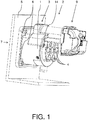
- the Fig. 1 shows a connector for electrically connecting an electric vehicle to a charging device.
- the connector has a socket 1 and a drive device 2, wherein the drive device 2 comprises an electromechanically driven locking device 3.
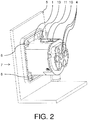
- Fig. 2 shows the jack in isolation while Fig. 3 the drive device 2 shows.
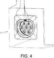
- Fig. 4 the socket 1 in another view.
- the socket 1 has a plurality of electrical contacts 4, which is configured for establishing an electrical connection with a corresponding connector of a second connector assigned to the electric vehicle or the charging device.
- the bushing 1 is inserted into a wall 5, for example of the electric vehicle or the charging device, and fastened to the wall 5 with screws 6.
- the locking device 3 has an axially to the insertion direction 7 of the sleeve movably arranged bolt 8, which is designed here as a cylindrical pin. As in Fig. 3 shown, the bolt 8 remains in this representation in its open position, the following is explained further.
- the drive device 2 has an actuator 9, which, triggered by an electrical pulse, enables a locking or unlocking of an interconnected male-female connector 1 pair.
- the bolt 8 is arranged to be movable axially to the insertion direction 7 of the socket 1 as already stated and drives through an opening 10 to the center line of the connector in the socket 1 in, so that connected to the socket 1 connector, which also has a corresponding opening 10 to the further opening is mechanically locked by retraction of the bolt in the two openings 10 against release of the male connector 1 pair.
- the drive device 2 and thus also the locking device 3, releasably secured to the bushing 1.
- This has the great advantage that first the socket 1 in the wall 5 can be fastened and then in a second step, the drive means 2 can be attached to the socket 1 in a particularly simple manner.
- a centering device 11 is provided, which is configured in two parts, on the one hand, on the bush 1 and on the drive device 2.
- the centering device 11 on the drive device 2 a semicircular, in the axial direction opposite to the insertion direction 7 of the socket 1 extending projection 12, so a contour which cooperates with a provided on the sleeve 1 semicircular extending groove 13 such that in the connected state of the bushing 1 with the drive device 2, the bush 1 and the drive device 2 form a positive connection in a predetermined position by the centering device 11.
- fastening means 14 which can be pre-mounted on the drive device 2 in the connected state of the drive device 2 with the socket 1 in the socket 1 can be inserted.
Landscapes
- Engineering & Computer Science (AREA)
- Computer Security & Cryptography (AREA)
- Power Engineering (AREA)
- Transportation (AREA)
- Mechanical Engineering (AREA)
- Details Of Connecting Devices For Male And Female Coupling (AREA)
Description
- Die Erfindung betrifft einen Steckverbinder zum elektrischen Anschließen eines Elektrofahrzeugs an eine Ladeeinrichtung, mit einem Stecker oder einer Buchse und einer elektrisch angetriebenen Verriegelungseinrichtung, wobei der Stecker bzw. die Buchse zum Herstellen einer elektrischen Verbindung mit einer zweiten Buchse bzw. einem zweiten Stecker eines zweiten dem Elektrofahrzeug oder der Ladeeinrichtung zugeordneten Steckverbinders ausgestaltet ist.
- Im Bereich von E-Mobility-Applikationen sind Steckverbinder mit elektrischer Verriegelung bekannt und normativ vorgesehen, um elektrische Energie von der Ladeeinrichtung zum Aufladen eines in dem Elektrofahrzeug vorgesehenen Fahrzeugakkumulators zu übertragen. Dazu können an der Ladeeinrichtung und/oder an dem Elektrofahrzeug jeweils ein Gerätestecker vorgesehen sein, so dass mittels eines Verbindungskabels, das an beiden Enden einen zu dem Gerätestecker korrespondierenden Kabelstecker aufweist, eine elektrische Verbindung zwischen der Ladeeinrichtung und dem Elektrofahrzeug herstellbar ist. Der Gerätestecker sowie der Kabelstecker können als Stecker oder Buchse ausgeführt sein, wobei der Kabelstecker oftmals als Stecker, also mit männlichen Kontakten, und der Gerätestecker oftmals als Buchse, also mit weiblichen Kontakten, ausgestaltet ist.
- Die Realisierung dieser elektrischen Verriegelung kann ein mechanisches Einfahren eines Zylinderstiftes senkrecht zur Steckrichtung der vollständig auf Anschlag gesteckten Steckverbinder vorsehen, wobei durch den Zylinderstift der Gerätestecker und der Kabelstecker in radialer Richtung über entsprechende Bohrungen oder Konturen durchdrungen werden können, so dass beim Verriegeln ein Formschluss in axialer Richtung erzeugt wird. Dadurch wird ein manuelles Lösen der verbundenen Steckverbinder verhindert, damit aufgrund von Sicherheitsaspekten unter elektrischer Last stehende Steckverbinder nicht voneinander getrennt werden können oder eine nicht vollständig durchgeführte Aufladung des Fahrzeugakkumulators nicht unterbrochen wird. In der Regel erfolgt der Antrieb des Zylinderstiftes elektromechanisch, beispielsweise über Hubmagnete oder Aktuatoren mit vorgeschalteter Mechanik.
-
DE 20 2010 014351 U1 beschreibt eine Anbausteckdose, wenigstens aufweisend einen verschieblichen Riegel zum Verriegeln eines in eine Steckeraufnahme der Anbausteckdose eingesteckten Steckers und einen Stellmotor, der, bezogen auf die Anbausteckdose, in einer ersten Montageposition montierbar ist, wobei der Stellmotor in dieser direkt mit dem Riegel koppelbar ist. - Sofern nun ein Gerätestecker in die Öffnung einer Wandung, beispielsweise eines Elektrofahrzeugs oder einer Ladeeinrichtung, eingesetzt wird, hat dies vielfach von der Rückseite der Wandung her zu erfolgen, da der Antrieb des Zylinderstiftes, insbesondere wenn der Zylinderstift senkrecht zur Steckrichtung der Steckverbinder einführbar ist, seitlich von dem Steckverbinder "absteht", so dass ein Durchführen des Steckverbinders einschließlich des Antriebs des Zylinderstiftes von der Vorderseite der Wandung durch die Öffnung hindurch verunmöglicht ist. Das bedeutet, dass ein nachträgliches Montieren eines derartigen Gerätesteckers, insbesondere wenn kein rückseitiges Anbringen des Gerätesteckers an die Wandung aufgrund beengter Platzverhältnisse möglich ist, in fast allen Fällen ausgeschlossen ist. Daher ist es die Aufgabe der Erfindung, einen Steckverbinder zum elektrischen Anschließen eines Elektrofahrzeugs mit einem elektromechanisch betriebenen Zylinderstift zum Verriegeln eines Stecker-Buchsen-Paares anzugeben, der auch nachträglich in eine Wandung und bei beengten Platzverhältnissen montierbar ist.
- Die Lösung der Aufgabe erfolgt erfindungsgemäß durch die Merkmale des unabhängigen Anspruchs. Vorteilhafte Ausgestaltungen der Erfindung sind in den Unteransprüchen angegeben.
- Demnach wird die Aufgabe der Erfindung gelöst durch einen Steckverbinder zum elektrischen Anschließen eines Elektrofahrzeugs an eine Ladeeinrichtung, mit einem Stecker oder einer Buchse und einer elektromechanisch angetriebenen Verriegelungseinrichtung, wobei der Stecker bzw. die Buchse zum Herstellen einer elektrischen Verbindung mit einer zweiten Buchse bzw. einem zweiten Stecker eines zweiten dem Elektrofahrzeug oder der Ladeeinrichtung zugeordneten Steckverbinders ausgestaltet ist, die Verriegelungseinrichtung axial zur Steckrichtung des Steckers bzw. der Buchse zum mechanischen Verriegeln und/oder Entriegeln eines miteinander verbundenen Stecker-Buchsen-Paares bewegbar ausgestaltet ist, und die Verriegelungseinrichtung und/oder der Stecker bzw. die Buchse eine derart ausgestaltete Zentriereinrichtung aufweist, dass die Verriegelungseinrichtung formschlüssig an dem Stecker bzw. an der Buchse in einer durch die Zentriereinrichtung vorbestimmten Position lösbar befestigbar ist.
- Es ist also ein wesentlicher Punkt der Erfindung, dass der Steckverbinder zweiteilig aufgebaut ist, nämlich einerseits den Stecker bzw. die Buchse und andererseits die Verriegelungsrichtung aufweist, wobei die Verriegelungsrichtung an dem Stecker bzw. an der Buchse lösbar befestigbar ist. Das bedeutet also, dass der Steckverbinder auch nachträglich unter schwierigen Licht- und/oder Platzverhältnissen in eine Öffnung einer Wandung eines Elektrofahrzeugs und/oder einer Ladeeinrichtung einsetzbar ist, so beispielsweise in einem ersten Schritt der Stecker bzw. die Buchse von der "Außenseite" der Wandung in die Öffnung einsetzbar ist und dann in einem zweiten Schritt die Verriegelungseinrichtung von der "Innenseite" der Wandung an den bereits in die Wandung eingesetzten Stecker bzw. an der Buchse befestigbar ist.
- Denn dadurch, dass aufgrund des Vorsehens der Zentriereinrichtung die Verriegelungsrichtung an dem Stecker bzw. an der Buchse formschlüssig in einer vorbestimmten Position befestigbar ist, ist das Zusammenfügen wesentlich vereinfacht. Konkret bedeutet das, dass die Verriegelungsrichtung, welche axial zur Steckrichtung des Steckers bzw. der Buchse zum mechanischen Verriegeln eines Stecker-Buchsen-Paares bewegbar ausgestaltet ist, aufgrund der Zentriereinrichtung an einer vorbestimmten Position an dem Stecker bzw. an der Buchse zu liegen kommt, also beispielsweise in der Ausgestaltung eines Zylinderstiftes zum mechanischen Verriegeln in eine Kontur des Steckers bzw. der Buchse axial zur Steckrichtung des Stecker-Buchsen-Paares einfahren kann. Mit anderen Worten ausgedrückt bedeutet dies, dass aufgrund der Ausgestaltung mit der Zentriereinrichtung ein passgenaues Zusammenfügen der Verriegelungsrichtung mit dem Stecker bzw. der Buchse in die vorbestimmte Position ermöglicht wird, somit also ein Bediener die Verriegelungsrichtung quasi blind mit dem Stecker bzw. der Buchse zusammenfügen kann.
- Grundsätzlich können der Stecker und/oder die Buchse als beliebige aus dem Stand der Technik bekannte Mittel zum Herstellen einer elektrischen Verbindung zwischen den Steckverbindern ausgestaltet sein, so beispielsweise als Kabelstecker und/oder Gerätestecker. Vorzugsweise weisen sowohl der Stecker als auch die Buchse eine Mehrzahl von elektrischen Kontakten auf, wobei besonders bevorzugt der Stecker mit männlichen Kontakten und die Buchse mit dazu korrespondierenden weiblichen Kontakten ausgestaltet ist. Ebenfalls kann der Steckverbinder in Verbindung mit einem beliebigen aus dem Stand der Technik bekannten Elektrofahrzeug sowie einer beliebigen Ladeeinrichtung verwendet werden.
- Das Verriegelungsmittel kann, wie nachfolgend im Detail weiter ausgeführt ist, beispielsweise als Zylinderstift oder als Bolzen ausgeführt sein, wobei der Zylinderstift bzw. Bolzen axial zur Steckrichtung des Steckers bzw. der Buchse zum mechanischen Verriegeln und/oder Entriegeln eines miteinander verbundenen Stecker-Buchsen-Paares bewegbar ausgestaltet ist. Besonders bevorzugt weist der Stecker und die Buchse eine jeweilige zur Verriegelungseinrichtung korrespondierende Kontur oder Öffnung auf, so dass die Verriegelungseinrichtung in ihrer Schließposition bevorzugt beide jeweiligen Konturen bzw. Öffnungen des Steckers und der Buchse durchdringt, so dass dadurch eine mechanische Verriegelung des miteinander verbundenen Stecker-Buchsen-Paares erfolgt. Entsprechend ist die Verriegelungseinrichtung in ihrer Öffnungsposition nicht im Eingriff mit vorgenannter Kontur bzw. Öffnung der zweiten Buchse bzw. des zweiten Steckers, so dass die zweite Buchse bzw. der zweite Stecker aus dem Stecker bzw. der Buchse entfernbar ist.
- Zur Ausgestaltung der Zentriereinrichtung gibt es ebenfalls verschiedene Möglichkeiten, so beispielsweise über eine an der Verriegelungseinrichtung vorgesehene Kontur mit entsprechend an dem Stecker bzw. an der Buchse vorgesehener Gegenkontur, wie nachfolgend im Detail weiter erläutert ist. Jedenfalls ist bevorzugt, dass durch die Zentriereinrichtung eine eindeutige, vorbestimmte Position beim Zusammenfügen der Verriegelungseinrichtung mit dem Stecker bzw. der Buchse erreicht wird, wobei die vorbestimmte Position bevorzugt wenigstens einen Formschluss in radialer Richtung zur Steckrichtung des Steckers bzw. der Buchse ausbildet, ganz besonders bevorzugt auch einen axialen Formschluss axial zur Steckrichtung des Steckers bzw. der Buchse ausbildet, dabei ganz besonders bevorzugt in Richtung der zweiten Buchse bzw. des zweiten Steckers, also bevorzugt in "Abziehrichtung" eines Stecker von einer korrespondierenden Buchse.
- Nach einer weiteren bevorzugten Ausführungsform der Erfindung ist vorgesehen, dass die Zentriereinrichtung derart ausgestaltet ist, dass durch Befestigen der Verriegelungseinrichtung an dem Stecker bzw. an der Buchse mittels einer ersten Bewegung der Verriegelungseinrichtung in radialer Richtung zur Steckrichtung des Steckers bzw. der Buchse und mittels einer zweiten Bewegung in axialer Richtung zur Steckrichtung des Steckers bzw. der Buchse die vorbestimmte Position erreichbar ist. Mit anderen Worten ausgedrückt ist die Zentriereinrichtung vorzugsweise derart ausgestaltet, dass beim Heranführen der Verriegelungseinrichtung "von hinten" an den Stecker bzw. an die Buchse und nachfolgendem "Absenken" der Verriegelungseinrichtung, also durch die erste Bewegung in radialer Richtung, und darauf folgendem "nach vorn Schieben", also durch die zweite Bewegung in axialer Richtung, die vorbestimmte Position erreichbar ist, in der die Verriegelungseinrichtung mit dem Stecker bzw. der Buchse formschlüssig verbunden ist bzw. die Verriegelungseinrichtung formschlüssig an dem Stecker bzw. an der Buchse befestigt ist. Durch eine derartige Ausgestaltung kann also die Verriegelungseinrichtung in besonders einfacher Weise auch bei ungünstigen Licht- und/oder schwierigem sowie beengten Platzverhältnissen an dem Stecker bzw. an der Buchse befestigt werden, so dass zum Verriegeln eines miteinander verbundenen Stecker-Buchsen-Paares die Verriegelungseinrichtung in der vorbestimmten bzw. definierten Position axial zur Steckrichtung des Steckers bzw. der Buchse bewegt werden kann.
- Grundsätzlich kann die Verriegelungseinrichtung beliebig ausgestaltet sein, wobei ganz besonders bevorzugt die Verriegelungseinrichtung als Bolzen oder als Zylinderstift ausgestaltet ist. Nach einer weiter bevorzugten Ausführungsform der Erfindung ist vorgesehen, dass der Stecker bzw. die Buchse eine Öffnung zum Einführen des Bolzens aufweist, die Öffnung und der Bolzen einen im Wesentlichen gleich großen Durchmesser aufweisen und der Bolzen in der vorbestimmten Position derart relativ zu dem Stecker bzw. zu der Buchse angeordnet ist, dass der Bolzen zum mechanischen Verriegeln eines miteinander verbundenen Stecker-Buchsen-Paares axial zur Steckrichtung des Steckers bzw. der Buchse in die Öffnung einführbar ist.
- Nach einer weiteren bevorzugten Ausführungsform der Erfindung ist vorgesehen, dass der Steckverbinder eine Antriebseinrichtung für die Verriegelungseinrichtung aufweist, wobei die Antriebseinrichtung die Verriegelungseinrichtung umfasst, die Zentriereinrichtung zweiteilig an der Antriebseinrichtung und an dem Stecker bzw. an der Buchse ausgestaltet ist und der an der Antriebseinrichtung vorgesehene erste Teil der Zentriereinrichtung eine sich halbkreisförmig, in axialer Richtung zur Steckrichtung des Steckers bzw. der Buchse erstreckende Auskragung aufweist und der an dem Stecker bzw. an der Buchse vorgesehene zweite Teil der Zentriereinrichtung eine sich halbkreisförmig erstreckende Nut zur formschlüssigen Aufnahme der Auskragung aufweist. Alternativ kann der erste Teil der Zentriereinrichtung eine Kontur aufweisen und der zweite Teil der Zentriereinrichtung eine Gegenkontur zur formschlüssigen Aufnahme der Kontur aufweisen. In jedem Fall ist gemäß dieser Ausführungsform vorgesehen, dass die Zentriereinrichtung mit einem ersten Teil an der Antriebseinrichtung angeordnet ist und mit einem zweiten Teil an dem Stecker bzw. an der Buchse angeordnet ist, so dass der erste Teil und der zweite Teil der Zentriereinrichtung derart zusammenwirken, dass durch das Zusammenfügen der Antriebseinrichtung bzw. der Verriegelungseinrichtung mit dem Stecker bzw. der Buchse die Verriegelungseinrichtung und der Stecker bzw. die Buchse die vorbestimmte Position eingehen.
- Nach einer noch weiteren bevorzugten Ausführungsform der Erfindung ist vorgesehen, dass die Antriebseinrichtung ein Befestigungsmittel zum Fixieren der an dem Stecker bzw. an der Buchse befestigten Antriebseinrichtung aufweist. Dabei ist ferner bevorzugt, dass das Befestigungsmittel als Schraube ausgeführt ist, beispielsweise als eine selbstschneidende Schraube, die an der Antriebseinrichtung vormontiert sein kann, so dass nach dem Zusammenfügen der Antriebseinrichtung mit dem Stecker bzw. der Buchse und nach Erreichen der vordefinierten Position durch das Befestigungsmittel eine Fixierung, vorzugsweise eine permanente Fixierung, der Antriebseinrichtung mit dem Stecker bzw. mit der Buchse erreicht wird. Dadurch kann ein "Kippen" der Antriebseinrichtung relativ zum Stecker bzw. zur Buchse verhindert werden, so dass ein noch verlässlicherer Betrieb der Antriebseinrichtung bzw. der Verriegelungseinrichtung gewährleistet werden kann.
- Grundsätzlich kann die elektromechanische Betätigung der Verriegelungseinrichtung durch beliebige aus dem Stand der Technik bekannte Mittel bewirkt werden, wobei jedoch besonders bevorzugt ist, dass die Antriebseinrichtung einen durch einen elektrischen Impuls ansteuerbaren Aktuator zum Verriegeln bzw. Entriegeln eines miteinander verbundenen Stecker-Buchsen-Paares aufweist. Zur Bereitstellung des elektrischen Impulses können eine Energiequelle oder andere Mittel vorgesehen sein, so beispielsweise ein Akkumulator, ein Kondensator und/oder eine Spule. Zudem kann vorgesehen sein, dass die Energiequelle durch die Ladeeinrichtung und/oder einen dem Elektrofahrzeug zugeordneten Fahrzeugakkumulator aufladbar ist.
- Nach einer weiteren bevorzugten Ausführungsform ist vorgesehen, dass der Steckverbinder derart zum Befestigen in einer Öffnung einer Wandung ausgestaltet ist, dass der Stecker bzw. die Buchse nur bei nicht an dem Stecker bzw. an der Buchse befestigten Verriegelungseinrichtung in die Öffnung von der einen Seite der Wandung her einsetzbar ist und die Verriegelungseinrichtung von der anderen Seite der Wandung an dem in die Öffnung eingesetzten Stecker bzw. Buchse befestigbar ist. Demnach ist also bevorzugt, dass der Steckverbinder nicht "als Ganzes" an der Wandung befestigbar ist, sondern derart ausgestaltet ist, dass immer zuerst der Stecker bzw. die Buchse in die Öffnung einer Wandung einzusetzen ist und dann in einem zweiten Schritt, vorzugsweise von der anderen Seite der Wandung her, die Verriegelungseinrichtung mit dem bereits in die Wandung eingesetzten Stecker bzw. der Buchse verbunden wird. Denn durch den mittels der Zentriereinrichtung erreichten Formschluss zwischen dem Stecker bzw. der Buchse und der Verriegelungseinrichtung wird ein "Kippen" vermieden, so dass eine verlässliche und sichere Betätigung der Verriegelungseinrichtung zum Verriegeln eines miteinander verbundenen Stecker-Buchsen-Paares möglich ist. "Miteinander verbunden" meint im Rahmen dieser Erfindung, dass die beiden Steckverbinder eine elektrische Verbindung zwischen dem Elektrofahrzeug und der Ladeeinrichtung bereitstellen und dazu vorzugsweise eine form- und/oder kraftschlüssige Verbindung zwischen ihren Steckern bzw. Buchsen aufweisen.
- Die Aufgabe der Erfindung wird weiterhin gelöst durch eine Steckverbinderanordnung mit einem Steckverbinder wie bereits ausgeführt und einem zweiten Steckverbinder, wobei der zweite Steckverbinder bevorzugt eine zweite Buchse bzw. einen zweiten Stecker aufweist, der korrespondierend zum Eingehen einer elektrischen Verbindung mit dem Stecker bzw. der Buchse ausgestaltet ist. Zudem wird die Aufgabe der Erfindung gelöst durch eine Ladeeinrichtung oder ein Elektrofahrzeug, mit einem Steckverbinder wie vorab ausgeführt.
- Nachfolgend wird die Erfindung unter Bezugnahme auf die anliegende Zeichnung anhand einer bevorzugten Ausführungsform näher erläutert.
- Es zeigen
- Fig. 1
- einen Steckverbinder mit einer Buchse und einer Antriebseinrichtung gemäß einer bevorzugten Ausführungsform der Erfindung,
- Fig. 2
- die Buchse gemäß der bevorzugten Ausführungsform der Erfindung,
- Fig. 3
- die Antriebseinrichtung gemäß der bevorzugten Ausführungsform der Erfindung, und
- Fig. 4
- die Buchse gemäß der bevorzugten Ausführungsform der Erfindung in einer zweiten Ansicht.
- Die
Fig. 1 zeigt einen Steckverbinder zum elektrischen Anschließen eines Elektrofahrzeugs an eine Ladeeinrichtung. Der Steckverbinder weist eine Buchse 1 sowie eine Antriebseinrichtung 2 auf, wobei die Antriebseinrichtung 2 eine elektromechanisch angetriebene Verriegelungseinrichtung 3 umfasst.Fig. 2 zeigt die Buchse in Alleinstellung, währendFig. 3 die Antriebseinrichtung 2 zeigt. Schließlich zeigtFig. 4 die Buchse 1 in einer weiteren Ansicht. - Die Buchse 1 weist eine Mehrzahl von elektrischen Kontakten 4 auf, die zum Herstellen einer elektrischen Verbindung mit einem korrespondierenden Stecker eines zweiten dem Elektrofahrzeug oder der Ladeeinrichtung zugeordneten Steckverbinder ausgestaltet ist. Die Buchse 1 ist in eine Wandung 5, beispielsweise des Elektrofahrzeugs oder der Ladeeinrichtung, eingesetzt und an der Wandung 5 mit Schrauben 6 befestigt.
- Die Verriegelungseinrichtung 3 weist einen axial zur Steckrichtung 7 der Buchse beweglich angeordneten Bolzen 8 auf, welcher vorliegend als Zylinderstift ausgestaltet ist. Wie in
Fig. 3 gezeigt, verharrt der Bolzen 8 in dieser Darstellung in seiner Öffnungsposition, die nachfolgend weiter erläutert ist. Zur Betätigung des Bolzens 8 weist die Antriebseinrichtung 2 einen Aktuator 9 auf, der durch einen elektrischen Impuls angesteuert ein Verriegeln bzw. Entriegeln eines miteinander verbundenen Stecker-Buchsen 1-Paares ermöglicht. - Dazu, also zum Verriegeln, ist der Bolzen 8 wie bereits ausgeführt axial zur Steckrichtung 7 der Buchse 1 beweglich angeordnet und fährt durch eine Öffnung 10 zur Mittenlinie des Steckverbinders in die Buchse 1 herein, so dass ein mit der Buchse 1 verbundener Stecker, der ebenfalls eine zu der Öffnung 10 korrespondierende weitere Öffnung aufweist, durch Einfahren des Bolzens in die beiden Öffnungen 10 mechanisch gegen Lösen des Stecker-Buchsen 1-Paares verriegelt ist.
- Gemäß der Erfindung ist nunmehr vorgesehen, dass die Antriebseinrichtung 2, und damit auch die Verriegelungseinrichtung 3, lösbar an der Buchse 1 befestigbar ist. Das hat den großen Vorteil, dass zunächst die Buchse 1 in der Wandung 5 befestigbar ist und danach in einem zweiten Schritt die Antriebseinrichtung 2 an der Buchse 1 in besonders einfacher Weise befestigt werden kann.
- Damit der Bolzen 8 der Antriebseinrichtung 2 passgenau zum Verriegeln eines Stecker-Buchsen 1-Paares in die Öffnung 10 Aktuatorbetrieben eingleiten kann, muss die Antriebseinrichtung 2 passgenau an der Buchse 1 befestigt werden. Zu diesem Zweck ist eine Zentriereinrichtung 11 vorgesehen, welche zweiteilig einerseits an der Buchse 1 sowie an der Antriebseinrichtung 2 ausgestaltet ist.
- Wie aus
Fig. 2 undFig. 3 ersichtlich, weist die Zentriereinrichtung 11 an der Antriebseinrichtung 2 eine sich halbkreisförmig, in axialer Richtung entgegen der Steckrichtung 7 der Buchse 1 erstreckende Auskragung 12 auf, also eine Kontur, die mit einer an der Buchse 1 vorgesehenen sich halbkreisförmig erstreckenden Nut 13 derart zusammenwirkt, dass im verbundenen Zustand der Buchse 1 mit der Antriebseinrichtung 2 die Buchse 1 und die Antriebseinrichtung 2 eine formschlüssige Verbindung in einer durch die Zentriereinrichtung 11 vorbestimmten Position eingehen. - Konkret bedeutet dies, dass durch die vorliegende und in
Fig. 2 undFig. 3 gezeigte Ausgestaltung der Zentriereinrichtung 11 mittels einer ersten Bewegung der Antriebseinrichtung 2 hin zur Buchse 1, also durch eine Bewegung der Antriebseinrichtung 2 in radialer Richtung zur Steckrichtung 7 der Buchse 1, und mittels einer zweiten Bewegung in axialer Richtung entgegen der Steckrichtung 7 der Buchse 1, die Auskragung 12 in die Aufnahme der Zentriereinrichtung 11, die vorliegend als Nut 13 ausgestaltet ist, hereingleitet, so dass dadurch die vorbestimmte Position erreicht wird. In dieser Position ist dann die Verriegelungseinrichtung 3 an der Buchse 1 derart zentriert, dass der Bolzen 8 in die Öffnung 10 einfahren kann. - Zur weiteren Fixierung der Antriebseinrichtung 2 an der Buchse 1 sind selbstschneidende Schrauben als Befestigungsmittel 14 vorgesehen, die an der Antriebseinrichtung 2 vormontiert im verbundenen Zustand der Antriebseinrichtung 2 mit der Buchse 1 in die Buchse 1 eingeführt werden können.
Bezugszeichenliste Buchse 1 Antriebseinrichtung 2 Verriegelungseinrichtung 3 Elektrische Kontakte 4 Wandung 5 Schraube 6 Steckrichtung 7 Bolzen 8 Aktuator 9 Öffnung 10 Zentriereinrichtung 11 Auskragung 12 Nut 13 Befestigungsmittel 14
Claims (10)
- Steckverbinder zum elektrischen Anschließen eines Elektrofahrzeugs an eine Ladeeinrichtung, mit einem Stecker oder einer Buchse (1) und einer elektromechanisch angetriebenen Verriegelungseinrichtung (3), wobei
der Stecker bzw. die Buchse (1) zum Herstellen einer elektrischen Verbindung mit einer zweiten Buchse bzw. einem zweiten Stecker eines zweiten dem Elektrofahrzeug oder der Ladeeinrichtung zugeordneten Steckverbinders ausgestaltet ist,
die Verriegelungseinrichtung (3) axial zur Steckrichtung (7) des Steckers bzw. der Buchse (1) zum mechanischen Verriegeln und/oder Entriegeln eines miteinander verbundenen Stecker-Buchsen (1)-Paares bewegbar ausgestaltet ist, und
die Verriegelungseinrichtung (3) und/oder der Stecker bzw. die Buchse (1) eine derart ausgestaltete Zentriereinrichtung (11) aufweist, dass die Verriegelungseinrichtung (3) formschlüssig an dem Stecker bzw. an der Buchse (1) in einer durch die Zentriereinrichtung (11) vorbestimmten Position lösbar befestigbar ist. - Steckverbinder nach dem vorhergehenden Anspruch, wobei die Zentriereinrichtung (11) derart ausgestaltet ist, dass durch Befestigen der Verriegelungseinrichtung (3) an dem Stecker bzw. an der Buchse (1) mittels einer ersten Bewegung der Verriegelungseinrichtung (3) in radialer Richtung zur Steckrichtung (7) des Steckers bzw. der Buchse (1) und mittels einer zweiten Bewegung in axialer Richtung zur Steckrichtung (7) des Steckers bzw. der Buchse (1) die vorbestimmte Position erreichbar ist.
- Steckverbinder nach einem der vorhergehenden Ansprüche, wobei die Verriegelungseinrichtung (3) als Bolzen (8) ausgestaltet ist.
- Steckverbinder nach dem vorhergehenden Anspruch, wobei der Stecker bzw. die Buchse (1) eine Öffnung (10) zum Einführen des Bolzens aufweist, die Öffnung (10) und der Bolzen einen im Wesentlichen gleich großen Durchmesser aufweisen und der Bolzen in der vorbestimmten Position derart relativ zu dem Stecker bzw. zu der Buchse (1) angeordnet ist, dass der Bolzen zum mechanischen Verriegeln eines miteinander verbundenen Stecker-Buchsen (1)-Paares axial zur Steckrichtung (7) des Steckers bzw. der Buchse (1) in die Öffnung (10) einführbar ist.
- Steckverbinder nach einem der vorhergehenden Ansprüche, mit einer Antriebseinrichtung (2) für die Verriegelungseinrichtung (3), wobei die Antriebseinrichtung (2) die Verriegelungseinrichtung (3) umfasst, die Zentriereinrichtung (11) zweiteilig an der Antriebseinrichtung (2) und an dem Stecker bzw. an der Buchse (1) ausgestaltet ist und der an der Antriebseinrichtung (2) vorgesehene erste Teil der Zentriereinrichtung (11) eine sich halbkreisförmig, in axialer Richtung zur Steckrichtung (7) des Steckers bzw. der Buchse (1) erstreckende Auskragung (12) aufweist und der an dem Stecker bzw. an der Buchse (1) vorgesehene zweite Teil der Zentriereinrichtung (11) eine sich halbkreisförmig erstreckende Nut (13) zur formschlüssigen Aufnahme der Auskragung (12) aufweist.
- Steckverbinder nach dem vorhergehenden Anspruch, wobei die Antriebseinrichtung ein Befestigungsmittel (14) zum Fixieren der an dem Stecker bzw. an der Buchse (1) befestigten Antriebseinrichtung (2) aufweist.
- Steckverbinder nach einem der vorhergehenden Ansprüche 5 oder 6, wobei die Antriebseinrichtung (2) einen durch einen elektrischen Impuls ansteuerbaren Aktuator (9) zum Verriegeln bzw. Entriegeln eines miteinander verbundenen Stecker-Buchsen (1)-Paares aufweist.
- Steckverbinder nach einem der vorhergehenden Ansprüche, wobei der Steckverbinder derart zum Befestigen in einer Öffnung einer Wandung (5) ausgestaltet ist, dass der Stecker bzw. die Buchse (1) nur bei nicht an dem Stecker bzw. an der Buchse (1) befestigten Verriegelungseinrichtung (3) in die Öffnung von der einen Seite der Wandung (5) her einsetzbar ist und die Verriegelungseinrichtung (3) von der anderen Seite der Wandung (5) an dem in die Öffnung eingesetzten Stecker bzw. an der Buchse (1) befestigbar ist.
- Steckverbinderanordnung mit einem Steckverbinder nach einem der vorhergehenden Ansprüche und einem zweiten Steckverbinder.
- Ladeeinrichtung oder Elektrofahrzeug, mit einem Steckverbinder nach einem der vorhergehenden Ansprüche.
Applications Claiming Priority (2)
| Application Number | Priority Date | Filing Date | Title |
|---|---|---|---|
| DE102012101690.9A DE102012101690B4 (de) | 2012-03-01 | 2012-03-01 | Steckverbinder, Steckverbinderanordnung, Ladeeinrichtung und Elektrofahrzeug |
| PCT/EP2013/054188 WO2013128005A1 (de) | 2012-03-01 | 2013-03-01 | Steckverbinder |
Publications (2)
| Publication Number | Publication Date |
|---|---|
| EP2820719A1 EP2820719A1 (de) | 2015-01-07 |
| EP2820719B1 true EP2820719B1 (de) | 2018-04-18 |
Family
ID=47998394
Family Applications (1)
| Application Number | Title | Priority Date | Filing Date |
|---|---|---|---|
| EP13712495.4A Not-in-force EP2820719B1 (de) | 2012-03-01 | 2013-03-01 | Steckverbinder |
Country Status (7)
| Country | Link |
|---|---|
| US (1) | US9365125B2 (de) |
| EP (1) | EP2820719B1 (de) |
| JP (1) | JP5824762B2 (de) |
| CN (1) | CN104145378B (de) |
| DE (1) | DE102012101690B4 (de) |
| IN (1) | IN2014DN07193A (de) |
| WO (1) | WO2013128005A1 (de) |
Families Citing this family (12)
| Publication number | Priority date | Publication date | Assignee | Title |
|---|---|---|---|---|
| JP5981294B2 (ja) * | 2012-10-12 | 2016-08-31 | 矢崎総業株式会社 | 充電インレット装置 |
| DE202013009554U1 (de) * | 2013-10-28 | 2015-01-29 | Kiekert Aktiengesellschaft | Elektrische Steckverbindung |
| DE102014015148B4 (de) * | 2014-10-13 | 2018-11-29 | Sumitomo Wiring Systems, Ltd. | Ladeverbinder und Verfahren zum Montieren desselben |
| CN106450976B (zh) * | 2016-10-27 | 2019-06-11 | 上海新力动力设备研究所 | 一种双脉冲固体发动机电连接器固定结构 |
| EP3382254B1 (de) * | 2017-03-29 | 2020-06-03 | TI Automotive (Fuldabrück) GmbH | Beheizte rohrleitung mit stecker sowie ein verfahren zum betrieb dieser rohrleitung |
| CN107546534A (zh) * | 2017-08-11 | 2018-01-05 | 中创弘源(北京)新能源科技股份有限公司 | 一种储能电柜用的接口固定座 |
| WO2019040485A1 (en) | 2017-08-21 | 2019-02-28 | Hubbel Incorporated | LOCKED ELECTRICAL CONTACT DEVICE |
| CN108808335A (zh) * | 2018-07-03 | 2018-11-13 | 深圳巴斯巴科技发展有限公司 | 一种带马达式电子锁交流供电端插座装置 |
| CN109994873B (zh) * | 2019-04-16 | 2024-10-01 | 陕西科技大学 | 一种防触电自弹自锁插座装置 |
| CN110397328B (zh) * | 2019-06-06 | 2024-05-24 | 江西中天智能装备股份有限公司 | 一种立体车库充电交换器装置 |
| DE102020132024A1 (de) * | 2020-12-02 | 2022-06-02 | Kiekert Aktiengesellschaft | Ladevorrichtung für ein Kraftfahrzeug |
| CN215299720U (zh) * | 2021-08-03 | 2021-12-24 | 长春捷翼汽车零部件有限公司 | 充电座及汽车 |
Family Cites Families (9)
| Publication number | Priority date | Publication date | Assignee | Title |
|---|---|---|---|---|
| JP2916348B2 (ja) * | 1993-07-22 | 1999-07-05 | 住友電装株式会社 | 電気自動車充電用コネクタ |
| JP5339983B2 (ja) | 2008-05-19 | 2013-11-13 | 富士重工業株式会社 | 電気自動車の制御装置 |
| DE102009016504A1 (de) * | 2009-04-08 | 2011-04-21 | Rwe Ag | Ladekabelverriegelungsvorrichtung und Verfahren zum Verriegeln eines Kabels |
| JP4947132B2 (ja) | 2009-11-30 | 2012-06-06 | 日立電線株式会社 | 接続構造 |
| DE102009057426A1 (de) * | 2009-12-09 | 2011-06-16 | Küster Holding GmbH | Verriegelungsvorrichtung, insbesondere für den Einsatz in oder an einem Fahrzeug, zur Sicherung der Teile eines Steckverbinders, Fahrzeug mit einer solchen Verriegelungsvorrichtung sowie Steckdose, Stecker und Steckverbinder |
| DE202010014351U1 (de) | 2010-10-18 | 2012-01-24 | Schletter Gmbh | Verriegelbare Anbausteckdose |
| CN202013972U (zh) * | 2010-11-10 | 2011-10-19 | 顾金华 | 用于电动汽车的电池接头装置 |
| CN202068024U (zh) * | 2011-04-26 | 2011-12-07 | 乐清市荣盛引进电器有限公司 | 一种电动汽车充电连接装置 |
| DE102011050536A1 (de) * | 2011-05-20 | 2012-11-22 | Phoenix Contact Gmbh & Co. Kg | Steckverbinder |
-
2012
- 2012-03-01 DE DE102012101690.9A patent/DE102012101690B4/de not_active Expired - Fee Related
-
2013
- 2013-03-01 JP JP2014557091A patent/JP5824762B2/ja not_active Expired - Fee Related
- 2013-03-01 US US14/372,434 patent/US9365125B2/en not_active Expired - Fee Related
- 2013-03-01 WO PCT/EP2013/054188 patent/WO2013128005A1/de not_active Ceased
- 2013-03-01 CN CN201380010243.7A patent/CN104145378B/zh not_active Expired - Fee Related
- 2013-03-01 IN IN7193DEN2014 patent/IN2014DN07193A/en unknown
- 2013-03-01 EP EP13712495.4A patent/EP2820719B1/de not_active Not-in-force
Non-Patent Citations (1)
| Title |
|---|
| None * |
Also Published As
| Publication number | Publication date |
|---|---|
| JP5824762B2 (ja) | 2015-12-02 |
| WO2013128005A1 (de) | 2013-09-06 |
| US20150004827A1 (en) | 2015-01-01 |
| IN2014DN07193A (de) | 2015-04-24 |
| EP2820719A1 (de) | 2015-01-07 |
| US9365125B2 (en) | 2016-06-14 |
| DE102012101690A1 (de) | 2013-09-05 |
| CN104145378B (zh) | 2017-04-19 |
| JP2015507342A (ja) | 2015-03-05 |
| CN104145378A (zh) | 2014-11-12 |
| DE102012101690B4 (de) | 2014-03-27 |
Similar Documents
| Publication | Publication Date | Title |
|---|---|---|
| DE102012101690B4 (de) | Steckverbinder, Steckverbinderanordnung, Ladeeinrichtung und Elektrofahrzeug | |
| EP2710688B1 (de) | Elektrischer steckverbinder | |
| EP2957000B1 (de) | Elektrischer rundsteckverbinder mit push-pull-verriegelung | |
| DE102015120921B4 (de) | Steckverbinder und Steckerverbinderanordnung | |
| EP3437163A1 (de) | Verriegelungsvorrichtung für steckverbinder | |
| EP2882049A1 (de) | Elektrische Steckverbindung | |
| DE102019114257B4 (de) | Steckverbinder mit Verriegelungssystem | |
| EP3069414B1 (de) | Prüfsteckerblock | |
| EP3665748B1 (de) | Steckverbinderteil mit einem verriegelungselement | |
| DE102016114577A1 (de) | Vorrichtung und Verfahren zur Kabeldurchführung durch einen Wanddurchbruch | |
| DE102011050938A1 (de) | Kabelstecker | |
| DE202015100360U1 (de) | Kabelhalter und Kabelhaltersystem | |
| DE102011087243B3 (de) | Elektrischer Steckverbinder mit Kontaktsicherung | |
| EP3257113B1 (de) | Hvil-system | |
| EP3403298B1 (de) | Steckverbinder | |
| DE102019114262B3 (de) | Steckverbinder mit Verriegelungssystem | |
| DE102012101687B4 (de) | Gerätestecker | |
| EP3790121A1 (de) | Steckverbinder und stecksystem | |
| DE102011052213B4 (de) | Kontakteinsetzanordnung | |
| DE102016104082B3 (de) | Elektrische Steckvorrichtung mit einem Rastmechanismus | |
| EP2587595B1 (de) | Steckverbindung und Verfahren zum Betreiben einer Steckverbindung für Hochvolt-Anwendungen | |
| DE102008006046A1 (de) | Elektrische Steckvorrichtung | |
| DE102017008167A1 (de) | Elektrische Verbindungsanordnung | |
| DE102017112629A1 (de) | Steckverbinder mit einem Verriegelungsteil | |
| DE102014006201A1 (de) | Kabelschuh, insbesondere für ein Kraftfahrzeug |
Legal Events
| Date | Code | Title | Description |
|---|---|---|---|
| PUAI | Public reference made under article 153(3) epc to a published international application that has entered the european phase |
Free format text: ORIGINAL CODE: 0009012 |
|
| 17P | Request for examination filed |
Effective date: 20140904 |
|
| AK | Designated contracting states |
Kind code of ref document: A1 Designated state(s): AL AT BE BG CH CY CZ DE DK EE ES FI FR GB GR HR HU IE IS IT LI LT LU LV MC MK MT NL NO PL PT RO RS SE SI SK SM TR |
|
| AX | Request for extension of the european patent |
Extension state: BA ME |
|
| DAX | Request for extension of the european patent (deleted) | ||
| GRAP | Despatch of communication of intention to grant a patent |
Free format text: ORIGINAL CODE: EPIDOSNIGR1 |
|
| STAA | Information on the status of an ep patent application or granted ep patent |
Free format text: STATUS: GRANT OF PATENT IS INTENDED |
|
| INTG | Intention to grant announced |
Effective date: 20171110 |
|
| GRAS | Grant fee paid |
Free format text: ORIGINAL CODE: EPIDOSNIGR3 |
|
| GRAA | (expected) grant |
Free format text: ORIGINAL CODE: 0009210 |
|
| STAA | Information on the status of an ep patent application or granted ep patent |
Free format text: STATUS: THE PATENT HAS BEEN GRANTED |
|
| AK | Designated contracting states |
Kind code of ref document: B1 Designated state(s): AL AT BE BG CH CY CZ DE DK EE ES FI FR GB GR HR HU IE IS IT LI LT LU LV MC MK MT NL NO PL PT RO RS SE SI SK SM TR |
|
| REG | Reference to a national code |
Ref country code: GB Ref legal event code: FG4D Free format text: NOT ENGLISH |
|
| REG | Reference to a national code |
Ref country code: CH Ref legal event code: EP |
|
| REG | Reference to a national code |
Ref country code: AT Ref legal event code: REF Ref document number: 991415 Country of ref document: AT Kind code of ref document: T Effective date: 20180515 |
|
| REG | Reference to a national code |
Ref country code: IE Ref legal event code: FG4D Free format text: LANGUAGE OF EP DOCUMENT: GERMAN |
|
| REG | Reference to a national code |
Ref country code: DE Ref legal event code: R096 Ref document number: 502013009949 Country of ref document: DE |
|
| REG | Reference to a national code |
Ref country code: NL Ref legal event code: MP Effective date: 20180418 |
|
| REG | Reference to a national code |
Ref country code: LT Ref legal event code: MG4D |
|
| PG25 | Lapsed in a contracting state [announced via postgrant information from national office to epo] |
Ref country code: NL Free format text: LAPSE BECAUSE OF FAILURE TO SUBMIT A TRANSLATION OF THE DESCRIPTION OR TO PAY THE FEE WITHIN THE PRESCRIBED TIME-LIMIT Effective date: 20180418 |
|
| PG25 | Lapsed in a contracting state [announced via postgrant information from national office to epo] |
Ref country code: PL Free format text: LAPSE BECAUSE OF FAILURE TO SUBMIT A TRANSLATION OF THE DESCRIPTION OR TO PAY THE FEE WITHIN THE PRESCRIBED TIME-LIMIT Effective date: 20180418 Ref country code: LT Free format text: LAPSE BECAUSE OF FAILURE TO SUBMIT A TRANSLATION OF THE DESCRIPTION OR TO PAY THE FEE WITHIN THE PRESCRIBED TIME-LIMIT Effective date: 20180418 Ref country code: BG Free format text: LAPSE BECAUSE OF FAILURE TO SUBMIT A TRANSLATION OF THE DESCRIPTION OR TO PAY THE FEE WITHIN THE PRESCRIBED TIME-LIMIT Effective date: 20180718 Ref country code: ES Free format text: LAPSE BECAUSE OF FAILURE TO SUBMIT A TRANSLATION OF THE DESCRIPTION OR TO PAY THE FEE WITHIN THE PRESCRIBED TIME-LIMIT Effective date: 20180418 Ref country code: FI Free format text: LAPSE BECAUSE OF FAILURE TO SUBMIT A TRANSLATION OF THE DESCRIPTION OR TO PAY THE FEE WITHIN THE PRESCRIBED TIME-LIMIT Effective date: 20180418 Ref country code: AL Free format text: LAPSE BECAUSE OF FAILURE TO SUBMIT A TRANSLATION OF THE DESCRIPTION OR TO PAY THE FEE WITHIN THE PRESCRIBED TIME-LIMIT Effective date: 20180418 Ref country code: SE Free format text: LAPSE BECAUSE OF FAILURE TO SUBMIT A TRANSLATION OF THE DESCRIPTION OR TO PAY THE FEE WITHIN THE PRESCRIBED TIME-LIMIT Effective date: 20180418 Ref country code: NO Free format text: LAPSE BECAUSE OF FAILURE TO SUBMIT A TRANSLATION OF THE DESCRIPTION OR TO PAY THE FEE WITHIN THE PRESCRIBED TIME-LIMIT Effective date: 20180718 |
|
| PG25 | Lapsed in a contracting state [announced via postgrant information from national office to epo] |
Ref country code: LV Free format text: LAPSE BECAUSE OF FAILURE TO SUBMIT A TRANSLATION OF THE DESCRIPTION OR TO PAY THE FEE WITHIN THE PRESCRIBED TIME-LIMIT Effective date: 20180418 Ref country code: GR Free format text: LAPSE BECAUSE OF FAILURE TO SUBMIT A TRANSLATION OF THE DESCRIPTION OR TO PAY THE FEE WITHIN THE PRESCRIBED TIME-LIMIT Effective date: 20180719 Ref country code: HR Free format text: LAPSE BECAUSE OF FAILURE TO SUBMIT A TRANSLATION OF THE DESCRIPTION OR TO PAY THE FEE WITHIN THE PRESCRIBED TIME-LIMIT Effective date: 20180418 Ref country code: RS Free format text: LAPSE BECAUSE OF FAILURE TO SUBMIT A TRANSLATION OF THE DESCRIPTION OR TO PAY THE FEE WITHIN THE PRESCRIBED TIME-LIMIT Effective date: 20180418 |
|
| PG25 | Lapsed in a contracting state [announced via postgrant information from national office to epo] |
Ref country code: PT Free format text: LAPSE BECAUSE OF FAILURE TO SUBMIT A TRANSLATION OF THE DESCRIPTION OR TO PAY THE FEE WITHIN THE PRESCRIBED TIME-LIMIT Effective date: 20180820 |
|
| REG | Reference to a national code |
Ref country code: DE Ref legal event code: R097 Ref document number: 502013009949 Country of ref document: DE |
|
| PG25 | Lapsed in a contracting state [announced via postgrant information from national office to epo] |
Ref country code: SK Free format text: LAPSE BECAUSE OF FAILURE TO SUBMIT A TRANSLATION OF THE DESCRIPTION OR TO PAY THE FEE WITHIN THE PRESCRIBED TIME-LIMIT Effective date: 20180418 Ref country code: CZ Free format text: LAPSE BECAUSE OF FAILURE TO SUBMIT A TRANSLATION OF THE DESCRIPTION OR TO PAY THE FEE WITHIN THE PRESCRIBED TIME-LIMIT Effective date: 20180418 Ref country code: RO Free format text: LAPSE BECAUSE OF FAILURE TO SUBMIT A TRANSLATION OF THE DESCRIPTION OR TO PAY THE FEE WITHIN THE PRESCRIBED TIME-LIMIT Effective date: 20180418 Ref country code: EE Free format text: LAPSE BECAUSE OF FAILURE TO SUBMIT A TRANSLATION OF THE DESCRIPTION OR TO PAY THE FEE WITHIN THE PRESCRIBED TIME-LIMIT Effective date: 20180418 Ref country code: DK Free format text: LAPSE BECAUSE OF FAILURE TO SUBMIT A TRANSLATION OF THE DESCRIPTION OR TO PAY THE FEE WITHIN THE PRESCRIBED TIME-LIMIT Effective date: 20180418 |
|
| PLBE | No opposition filed within time limit |
Free format text: ORIGINAL CODE: 0009261 |
|
| STAA | Information on the status of an ep patent application or granted ep patent |
Free format text: STATUS: NO OPPOSITION FILED WITHIN TIME LIMIT |
|
| PG25 | Lapsed in a contracting state [announced via postgrant information from national office to epo] |
Ref country code: IT Free format text: LAPSE BECAUSE OF FAILURE TO SUBMIT A TRANSLATION OF THE DESCRIPTION OR TO PAY THE FEE WITHIN THE PRESCRIBED TIME-LIMIT Effective date: 20180418 Ref country code: SM Free format text: LAPSE BECAUSE OF FAILURE TO SUBMIT A TRANSLATION OF THE DESCRIPTION OR TO PAY THE FEE WITHIN THE PRESCRIBED TIME-LIMIT Effective date: 20180418 |
|
| 26N | No opposition filed |
Effective date: 20190121 |
|
| PG25 | Lapsed in a contracting state [announced via postgrant information from national office to epo] |
Ref country code: SI Free format text: LAPSE BECAUSE OF FAILURE TO SUBMIT A TRANSLATION OF THE DESCRIPTION OR TO PAY THE FEE WITHIN THE PRESCRIBED TIME-LIMIT Effective date: 20180418 |
|
| PG25 | Lapsed in a contracting state [announced via postgrant information from national office to epo] |
Ref country code: MC Free format text: LAPSE BECAUSE OF FAILURE TO SUBMIT A TRANSLATION OF THE DESCRIPTION OR TO PAY THE FEE WITHIN THE PRESCRIBED TIME-LIMIT Effective date: 20180418 |
|
| REG | Reference to a national code |
Ref country code: CH Ref legal event code: PL |
|
| GBPC | Gb: european patent ceased through non-payment of renewal fee |
Effective date: 20190301 |
|
| PG25 | Lapsed in a contracting state [announced via postgrant information from national office to epo] |
Ref country code: LU Free format text: LAPSE BECAUSE OF NON-PAYMENT OF DUE FEES Effective date: 20190301 |
|
| REG | Reference to a national code |
Ref country code: BE Ref legal event code: MM Effective date: 20190331 |
|
| PG25 | Lapsed in a contracting state [announced via postgrant information from national office to epo] |
Ref country code: GB Free format text: LAPSE BECAUSE OF NON-PAYMENT OF DUE FEES Effective date: 20190301 Ref country code: IE Free format text: LAPSE BECAUSE OF NON-PAYMENT OF DUE FEES Effective date: 20190301 Ref country code: CH Free format text: LAPSE BECAUSE OF NON-PAYMENT OF DUE FEES Effective date: 20190331 Ref country code: LI Free format text: LAPSE BECAUSE OF NON-PAYMENT OF DUE FEES Effective date: 20190331 |
|
| PG25 | Lapsed in a contracting state [announced via postgrant information from national office to epo] |
Ref country code: FR Free format text: LAPSE BECAUSE OF NON-PAYMENT OF DUE FEES Effective date: 20190331 Ref country code: BE Free format text: LAPSE BECAUSE OF NON-PAYMENT OF DUE FEES Effective date: 20190331 |
|
| PG25 | Lapsed in a contracting state [announced via postgrant information from national office to epo] |
Ref country code: TR Free format text: LAPSE BECAUSE OF FAILURE TO SUBMIT A TRANSLATION OF THE DESCRIPTION OR TO PAY THE FEE WITHIN THE PRESCRIBED TIME-LIMIT Effective date: 20180418 |
|
| PG25 | Lapsed in a contracting state [announced via postgrant information from national office to epo] |
Ref country code: MT Free format text: LAPSE BECAUSE OF FAILURE TO SUBMIT A TRANSLATION OF THE DESCRIPTION OR TO PAY THE FEE WITHIN THE PRESCRIBED TIME-LIMIT Effective date: 20180418 |
|
| REG | Reference to a national code |
Ref country code: AT Ref legal event code: MM01 Ref document number: 991415 Country of ref document: AT Kind code of ref document: T Effective date: 20190301 |
|
| PG25 | Lapsed in a contracting state [announced via postgrant information from national office to epo] |
Ref country code: AT Free format text: LAPSE BECAUSE OF NON-PAYMENT OF DUE FEES Effective date: 20190301 |
|
| PG25 | Lapsed in a contracting state [announced via postgrant information from national office to epo] |
Ref country code: CY Free format text: LAPSE BECAUSE OF FAILURE TO SUBMIT A TRANSLATION OF THE DESCRIPTION OR TO PAY THE FEE WITHIN THE PRESCRIBED TIME-LIMIT Effective date: 20180418 |
|
| PG25 | Lapsed in a contracting state [announced via postgrant information from national office to epo] |
Ref country code: IS Free format text: LAPSE BECAUSE OF FAILURE TO SUBMIT A TRANSLATION OF THE DESCRIPTION OR TO PAY THE FEE WITHIN THE PRESCRIBED TIME-LIMIT Effective date: 20180818 |
|
| PG25 | Lapsed in a contracting state [announced via postgrant information from national office to epo] |
Ref country code: HU Free format text: LAPSE BECAUSE OF FAILURE TO SUBMIT A TRANSLATION OF THE DESCRIPTION OR TO PAY THE FEE WITHIN THE PRESCRIBED TIME-LIMIT; INVALID AB INITIO Effective date: 20130301 |
|
| REG | Reference to a national code |
Ref country code: DE Ref legal event code: R084 Ref document number: 502013009949 Country of ref document: DE |
|
| PG25 | Lapsed in a contracting state [announced via postgrant information from national office to epo] |
Ref country code: MK Free format text: LAPSE BECAUSE OF FAILURE TO SUBMIT A TRANSLATION OF THE DESCRIPTION OR TO PAY THE FEE WITHIN THE PRESCRIBED TIME-LIMIT Effective date: 20180418 |
|
| P01 | Opt-out of the competence of the unified patent court (upc) registered |
Effective date: 20230424 |
|
| PGFP | Annual fee paid to national office [announced via postgrant information from national office to epo] |
Ref country code: DE Payment date: 20240529 Year of fee payment: 12 |
|
| REG | Reference to a national code |
Ref country code: DE Ref legal event code: R119 Ref document number: 502013009949 Country of ref document: DE |
|
| PG25 | Lapsed in a contracting state [announced via postgrant information from national office to epo] |
Ref country code: DE Free format text: LAPSE BECAUSE OF NON-PAYMENT OF DUE FEES Effective date: 20251001 |