EP2818706A1 - Compresseur motorisé - Google Patents
Compresseur motorisé Download PDFInfo
- Publication number
- EP2818706A1 EP2818706A1 EP14173416.0A EP14173416A EP2818706A1 EP 2818706 A1 EP2818706 A1 EP 2818706A1 EP 14173416 A EP14173416 A EP 14173416A EP 2818706 A1 EP2818706 A1 EP 2818706A1
- Authority
- EP
- European Patent Office
- Prior art keywords
- capacitor
- circuit board
- motor
- side wall
- driven compressor
- Prior art date
- Legal status (The legal status is an assumption and is not a legal conclusion. Google has not performed a legal analysis and makes no representation as to the accuracy of the status listed.)
- Withdrawn
Links
- 239000003990 capacitor Substances 0.000 claims abstract description 137
- 230000006835 compression Effects 0.000 claims description 18
- 238000007906 compression Methods 0.000 claims description 18
- 239000003507 refrigerant Substances 0.000 claims description 11
- 230000008878 coupling Effects 0.000 description 16
- 238000010168 coupling process Methods 0.000 description 16
- 238000005859 coupling reaction Methods 0.000 description 16
- 230000004308 accommodation Effects 0.000 description 10
- 229910052782 aluminium Inorganic materials 0.000 description 2
- XAGFODPZIPBFFR-UHFFFAOYSA-N aluminium Chemical compound [Al] XAGFODPZIPBFFR-UHFFFAOYSA-N 0.000 description 2
- 238000005452 bending Methods 0.000 description 2
- 238000009413 insulation Methods 0.000 description 2
- 229910052751 metal Inorganic materials 0.000 description 2
- 239000002184 metal Substances 0.000 description 2
- 238000000034 method Methods 0.000 description 1
Images
Classifications
-
- F—MECHANICAL ENGINEERING; LIGHTING; HEATING; WEAPONS; BLASTING
- F04—POSITIVE - DISPLACEMENT MACHINES FOR LIQUIDS; PUMPS FOR LIQUIDS OR ELASTIC FLUIDS
- F04D—NON-POSITIVE-DISPLACEMENT PUMPS
- F04D25/00—Pumping installations or systems
- F04D25/02—Units comprising pumps and their driving means
- F04D25/06—Units comprising pumps and their driving means the pump being electrically driven
- F04D25/0693—Details or arrangements of the wiring
-
- F—MECHANICAL ENGINEERING; LIGHTING; HEATING; WEAPONS; BLASTING
- F04—POSITIVE - DISPLACEMENT MACHINES FOR LIQUIDS; PUMPS FOR LIQUIDS OR ELASTIC FLUIDS
- F04B—POSITIVE-DISPLACEMENT MACHINES FOR LIQUIDS; PUMPS
- F04B27/00—Multi-cylinder pumps specially adapted for elastic fluids and characterised by number or arrangement of cylinders
- F04B27/08—Multi-cylinder pumps specially adapted for elastic fluids and characterised by number or arrangement of cylinders having cylinders coaxial with, or parallel or inclined to, main shaft axis
- F04B27/0873—Component parts, e.g. sealings; Manufacturing or assembly thereof
-
- F—MECHANICAL ENGINEERING; LIGHTING; HEATING; WEAPONS; BLASTING
- F04—POSITIVE - DISPLACEMENT MACHINES FOR LIQUIDS; PUMPS FOR LIQUIDS OR ELASTIC FLUIDS
- F04B—POSITIVE-DISPLACEMENT MACHINES FOR LIQUIDS; PUMPS
- F04B35/00—Piston pumps specially adapted for elastic fluids and characterised by the driving means to their working members, or by combination with, or adaptation to, specific driving engines or motors, not otherwise provided for
- F04B35/04—Piston pumps specially adapted for elastic fluids and characterised by the driving means to their working members, or by combination with, or adaptation to, specific driving engines or motors, not otherwise provided for the means being electric
-
- F—MECHANICAL ENGINEERING; LIGHTING; HEATING; WEAPONS; BLASTING
- F04—POSITIVE - DISPLACEMENT MACHINES FOR LIQUIDS; PUMPS FOR LIQUIDS OR ELASTIC FLUIDS
- F04B—POSITIVE-DISPLACEMENT MACHINES FOR LIQUIDS; PUMPS
- F04B39/00—Component parts, details, or accessories, of pumps or pumping systems specially adapted for elastic fluids, not otherwise provided for in, or of interest apart from, groups F04B25/00 - F04B37/00
- F04B39/12—Casings; Cylinders; Cylinder heads; Fluid connections
- F04B39/121—Casings
-
- F—MECHANICAL ENGINEERING; LIGHTING; HEATING; WEAPONS; BLASTING
- F04—POSITIVE - DISPLACEMENT MACHINES FOR LIQUIDS; PUMPS FOR LIQUIDS OR ELASTIC FLUIDS
- F04C—ROTARY-PISTON, OR OSCILLATING-PISTON, POSITIVE-DISPLACEMENT MACHINES FOR LIQUIDS; ROTARY-PISTON, OR OSCILLATING-PISTON, POSITIVE-DISPLACEMENT PUMPS
- F04C18/00—Rotary-piston pumps specially adapted for elastic fluids
- F04C18/02—Rotary-piston pumps specially adapted for elastic fluids of arcuate-engagement type, i.e. with circular translatory movement of co-operating members, each member having the same number of teeth or tooth-equivalents
- F04C18/0207—Rotary-piston pumps specially adapted for elastic fluids of arcuate-engagement type, i.e. with circular translatory movement of co-operating members, each member having the same number of teeth or tooth-equivalents both members having co-operating elements in spiral form
- F04C18/0215—Rotary-piston pumps specially adapted for elastic fluids of arcuate-engagement type, i.e. with circular translatory movement of co-operating members, each member having the same number of teeth or tooth-equivalents both members having co-operating elements in spiral form where only one member is moving
-
- F—MECHANICAL ENGINEERING; LIGHTING; HEATING; WEAPONS; BLASTING
- F04—POSITIVE - DISPLACEMENT MACHINES FOR LIQUIDS; PUMPS FOR LIQUIDS OR ELASTIC FLUIDS
- F04C—ROTARY-PISTON, OR OSCILLATING-PISTON, POSITIVE-DISPLACEMENT MACHINES FOR LIQUIDS; ROTARY-PISTON, OR OSCILLATING-PISTON, POSITIVE-DISPLACEMENT PUMPS
- F04C23/00—Combinations of two or more pumps, each being of rotary-piston or oscillating-piston type, specially adapted for elastic fluids; Pumping installations specially adapted for elastic fluids; Multi-stage pumps specially adapted for elastic fluids
- F04C23/008—Hermetic pumps
-
- H—ELECTRICITY
- H02—GENERATION; CONVERSION OR DISTRIBUTION OF ELECTRIC POWER
- H02K—DYNAMO-ELECTRIC MACHINES
- H02K11/00—Structural association of dynamo-electric machines with electric components or with devices for shielding, monitoring or protection
- H02K11/30—Structural association with control circuits or drive circuits
- H02K11/33—Drive circuits, e.g. power electronics
-
- F—MECHANICAL ENGINEERING; LIGHTING; HEATING; WEAPONS; BLASTING
- F04—POSITIVE - DISPLACEMENT MACHINES FOR LIQUIDS; PUMPS FOR LIQUIDS OR ELASTIC FLUIDS
- F04C—ROTARY-PISTON, OR OSCILLATING-PISTON, POSITIVE-DISPLACEMENT MACHINES FOR LIQUIDS; ROTARY-PISTON, OR OSCILLATING-PISTON, POSITIVE-DISPLACEMENT PUMPS
- F04C2240/00—Components
- F04C2240/80—Other components
- F04C2240/808—Electronic circuits (e.g. inverters) installed inside the machine
Definitions
- the present invention relates to a motor-driven compressor that includes a compression unit, which compresses refrigerant, an electric motor, which drives the compression unit, and a motor driving circuit, which drives the electric motor.
- the motor-driven compressor includes a motor driving circuit, which includes a planer circuit board and a plurality of electric components of various types.
- the electric components which are electrically connected to the circuit board, include a switching element and a plurality of capacitors, for example.
- the capacitors are provided on the circuit board. Each capacitor includes protruding leads and is electrically connected to the circuit board through the leads. The capacitors are held by a capacitor holder.
- the capacitors are arranged such that the protruding direction of the leads is perpendicular to the mounting surface of the circuit board, on which various types of the electric components are mounted, the size of the motor-driven compressor is increased in the direction perpendicular to the mounting surface of the circuit board. Accordingly, the capacitors may be arranged such that the protruding direction of the leads is in parallel with the mounting surface of the circuit board, and the leads are bent toward the mounting surface of the circuit board. This reduces the size of the motor-driven compressor in the direction perpendicular to the mounting surface of the circuit board in comparison to the case where the leads are not bent and the capacitors are arranged such that the protruding direction of the leads is perpendicular to the mounting surface of the circuit board.
- the positions of the leads at which the bent portions are formed vary between the capacitors during the bending process of the leads. Accordingly, when the leads of each capacitor and the circuit board are connected to each other in the state where the capacitor is held by the capacitor holder, the positions of the leads, which extend toward the mounting surface of the circuit board, may be shifted with respect to portions of the circuit board to which the leads are to be connected. This makes a connection operation between the leads of each capacitor and the circuit board difficult.
- a motor-driven compressor including: a compression unit, an electric motor, a housing, a motor driving circuit, and a capacitor holder.
- the compression unit is adapted to compress refrigerant.
- the electric motor is adapted to drive the compression unit.
- the housing accommodates the compression unit and the electric motor.
- the motor driving circuit is adapted to drive the electric motor and includes a circuit board and a capacitor.
- the capacitor is electrically connected through a lead to the circuit board.
- the capacitor holder is made of a plastic and holds the capacitor.
- the capacitor holder includes a side wall, which covers a side surface of the capacitor. The lead protrudes from the side surface.
- the side wall includes a through-hole, which opens through each of a first end surface of the side wall facing the circuit board and a second end surface of the side wall opposite to the first end surface.
- the through-hole guides the lead toward a portion of the circuit board to which the lead is to be connected.
- the side wall includes a wall surface facing the capacitor, and the side wall includes a slit in the wall surface, which is continuous with the through-hole and opens opposite to the circuit board.
- a motor-driven compressor 10 includes a housing H.
- the housing H includes a discharge housing member 11, a suction housing member 12, and a cover 13, which are made of a metal, preferably aluminum.
- the discharge housing member 11, the suction housing member 12, and the cover 13 are cylindrical and each include a closed end.
- the suction housing member 12 is coupled to the discharge housing member 11.
- the suction housing member 12 has a circumferential wall including a suction port (not shown) connected to an external refrigerant circuit (not shown).
- the discharge housing member 11 includes a discharge port 14 connected to the external refrigerant circuit.
- the suction housing member 12 accommodates a compression unit 15 (indicated by the broken lines in Fig. 1 ), which compresses refrigerant, and an electric motor 16, which drives the compression unit 15.
- the compression unit 15 of the present embodiment includes a fixed scroll, which is fixed in the suction housing member 12, and a movable scroll, which is engaged with the fixed scroll.
- a stator 17 is fixed to the inner surface of the suction housing member 12.
- the stator 17 includes a stator core 17a, which is fixed to the inner surface of the suction housing member 12, and coils 17b, which are wound around teeth (not shown) of the stator core 17a.
- a rotatable rotation shaft 19 extends through the stator 17 in the suction housing member 12.
- a rotor 18 is fixed to the rotation shaft 19.
- the suction housing member 12 has an end wall 12a to which the cover 13 is coupled.
- a planar coupling base 31 is arranged between the suction housing member 12 and the cover 13.
- the coupling base 31 is made of a metal, preferably aluminum.
- the coupling base 31 is coupled to the end wall 12a of the suction housing member 12.
- the coupling base 31 is thermally coupled to the suction housing member 12.
- the cover 13 and the coupling base 31 define an accommodation chamber 13a in the housing H.
- the accommodation chamber 13a accommodates a motor driving circuit 20 that drives the electric motor 16.
- the compression unit 15, the electric motor 16, and the motor driving circuit 20 are arranged in this order along the axis L of the rotation shaft 19 (in the axial direction).
- the electric motor 16 is supplied with power that is controlled by the motor driving circuit 20. This rotates the rotor 18 and the rotation shaft 19 at a controlled rotation speed and drives the compression unit 15.
- the driving of the compression unit 15 draws refrigerant from the external refrigerant circuit into the suction housing member 12 through the suction port, compresses the refrigerant in the suction housing member 12 with the compression unit 15, and discharges the compressed refrigerant to the external refrigerant circuit through the discharge port 14.
- the motor driving circuit 20 includes a flat circuit board 21 and a plurality of electric components of various types, which are electrically connected to the circuit board 21.
- the circuit board 21 is arranged in the accommodation chamber 13a such that a mounting surface 21a of the circuit board 21 on which the electric components are arranged is perpendicular to the axis of the rotation shaft 19.
- the electric components include film capacitors 22, for example.
- the motor driving circuit 20 includes a plurality of film capacitors 22. Each film capacitor 22 includes a flat, rectangular casing. Each film capacitor 22 includes a side surface 22e, from which leads 22a protrude. The leads 22a electrically connect the film capacitor 22 to the circuit board 21.
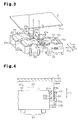
- a plastic capacitor holder 23 holds the film capacitors 22.
- the capacitor holder 23, which holds the film capacitors 22, is coupled to the side of the coupling base 31 that is opposite to the end wall 12a of the suction housing member 12.
- a plurality of bosses 31f projects from the surface of the coupling base 31 that is opposite to the end wall 12a of the suction housing member 12.
- Bolts B1 are inserted through the cover 13 and engaged with the corresponding bosses 31f to fasten the coupling base 31 to the cover 13. Accordingly, the cover 13, the coupling base 31, and the motor driving circuit 20 are combined to form a module.
- a bolt B2 fastens the cover 13, which is combined with the coupling base 31 and the motor driving circuit 20, to the suction housing member 12.
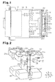
- each film capacitor 22 is arranged such that the projection direction (the direction of arrow X1) of the leads 22a from the side surface 22e and the mounting surface 21a of the circuit board 21 are parallel with each other. Each lead 22a is bent toward the mounting surface 21a of circuit board 21.
- the capacitor holder 23 includes a plurality of accommodation portions 23a, each of which accommodates the corresponding film capacitor 22.
- Each accommodation portion 23a includes a hollowed polygonal shape having a side wall 23e as one side, which covers the corresponding side surface 22e of the film capacitor 22 such that the accommodation portion 23a surrounds four sides of the corresponding film capacitor 22.
- the side wall 23e of the capacitor holder 23 includes a plurality of through-holes 23h, which open through each of the first end surface 231 of the side wall 23e facing the circuit board 21 and the second end surface 232 of the side wall 23e opposite to the first end surface 231 and guide the corresponding leads 22a toward the portions of the circuit board 21 to which the leads 22a are to be connected.
- each accommodation portion 23a of the capacitor holder 23 includes a plurality of first retaining pieces 25.
- the first retaining pieces 25 extend at positions facing the circuit boards 21, and engage with the end surface of the corresponding film capacitor 22 opposite to the coupling base 31.
- the accommodation portion 23a of the capacitor holder 23 also includes a plurality of second retaining pieces 26.
- the second retaining pieces 26 extend at positions opposite to the circuit board 21, and engage with the other end surface of the corresponding film capacitor 22 facing the coupling base 31.
- the side wall 23e positioned between the side surfaces 22e that are arranged facing each other includes the through-holes 23h corresponding to each of the film capacitors 22 that are adjacent to each other.
- the first end surface 231 of each side wall 23e includes the openings of the through-holes 23h corresponding to one of the film capacitors 22 that are adjacent to each other. The openings are arranged on the same straight line.
- the film capacitors 22 that are adjacent to each other are arranged shifted from each other in the direction in which the openings of the through-holes 23h are arranged (direction of arrow Z1).
- the side wall 23e includes a wall surface 233 facing the film capacitor 22.
- the wall surface 233 includes a slit 23b, which is continuous with the through-holes 23h and extend toward the circuit board 21 from a portion of the side wall 23e opposite to the circuit board 21.
- the slit opens opposite to the circuit board.
- the basal portion of each lead 22a with respect to the bent portion can extend through the slit 23b.
- Each film capacitor 22 is inserted into the corresponding accommodation portion 23a in the extended direction, in which the leads 22a extend toward the mounting surface 21a of the circuit board 21 (direction of arrow Y1).
- the leads 22a which extend toward the mounting surface 21a of the circuit board 21, then extend through the corresponding through-holes 23h and are guided to the corresponding portions of the circuit board 21 to which the leads 22a are to be connected. Further, the basal portion of each lead 22a with respect to the bent portion extends through the slit 23b and is covered by the capacitor holder 23. Each film capacitor 22 is held between the first retaining pieces 25 and the second retaining pieces 26. This maintains the state where the accommodation portions 23a accommodate the corresponding film capacitors 22.
- Each lead 22a extends from the side surface 22e of the corresponding film capacitor 22, and its basal portion with respect to the bent portion extends through the slit 23b.
- Each lead 22a, which extends toward the mounting surface 21a of the circuit board 21, extends through the corresponding through-hole 23h. This maintains the film capacitors 22 in the capacitor holder 23 in the state where the leads 22a, which extend toward the mounting surface 21a of the circuit board 21, are positioned at the corresponding portions of the circuit board 21 to which the leads 22a are to be connected. This facilitates the operation of coupling the leads 22a of each film capacitor 22 to the circuit board 21 in the state where the film capacitors 22 are held by the capacitor holder 23.
- the leads 22a which extend toward the mounting surface 21a of the circuit board 21, extend through the corresponding through-holes 23h. This limits the bending of the leads 22a, which extend toward the mounting surface 21a of the circuit board 21, when coupling the leads 22a of each film capacitor 22 to the circuit board 21. This reduces the stress acting on the leads 22a.
- each lead 22a with respect to the bent portion may be exposed from the capacitor holder 23.
- the through-holes 23h may be formed in the side wall 23e such that the openings of the through-holes 23h each corresponding to one of the film capacitors 22 that are adjacent to each other are arranged in the protruding direction (direction of arrow X1) of the leads 22a from the side surface 22e of each film capacitor 22.
- the through-holes 23h each corresponding to one of the film capacitors 22 that are adjacent to each other may be formed in separate side walls.
- the capacitor holder 23 may be configured to hold a single film capacitor 22.
- the number of the film capacitor 22 is not particularly limited. That is, the number may be appropriately changed.
- the capacitors may include an electrolytic capacitor, for example.
- the motor driving circuit 20 may be located radially outward of the rotation shaft 19.
- the compression unit 15 may be of a piston type or a vane type, for example.
Landscapes
- Engineering & Computer Science (AREA)
- Mechanical Engineering (AREA)
- General Engineering & Computer Science (AREA)
- Manufacturing & Machinery (AREA)
- Microelectronics & Electronic Packaging (AREA)
- Power Engineering (AREA)
- Compressor (AREA)
Applications Claiming Priority (1)
| Application Number | Priority Date | Filing Date | Title |
|---|---|---|---|
| JP2013132614A JP2015007391A (ja) | 2013-06-25 | 2013-06-25 | 電動圧縮機 |
Publications (1)
| Publication Number | Publication Date |
|---|---|
| EP2818706A1 true EP2818706A1 (fr) | 2014-12-31 |
Family
ID=50979614
Family Applications (1)
| Application Number | Title | Priority Date | Filing Date |
|---|---|---|---|
| EP14173416.0A Withdrawn EP2818706A1 (fr) | 2013-06-25 | 2014-06-23 | Compresseur motorisé |
Country Status (5)
| Country | Link |
|---|---|
| US (1) | US20140377095A1 (fr) |
| EP (1) | EP2818706A1 (fr) |
| JP (1) | JP2015007391A (fr) |
| KR (1) | KR20150000835A (fr) |
| CN (1) | CN104251213A (fr) |
Cited By (1)
| Publication number | Priority date | Publication date | Assignee | Title |
|---|---|---|---|---|
| FR3040744A1 (fr) * | 2015-09-09 | 2017-03-10 | Valeo Systemes De Controle Moteur | Compresseur de suralimentation electrique |
Families Citing this family (3)
| Publication number | Priority date | Publication date | Assignee | Title |
|---|---|---|---|---|
| CN107635804B (zh) * | 2015-11-27 | 2020-06-26 | 翰昂汽车零部件有限公司 | 制冷制热模块 |
| JP6814607B2 (ja) | 2016-11-11 | 2021-01-20 | 三菱重工サーマルシステムズ株式会社 | 電動圧縮機 |
| JP2023009908A (ja) * | 2021-07-08 | 2023-01-20 | 株式会社豊田自動織機 | 電動圧縮機 |
Citations (5)
| Publication number | Priority date | Publication date | Assignee | Title |
|---|---|---|---|---|
| EP1840378A2 (fr) * | 2006-03-29 | 2007-10-03 | Kabushiki Kaisha Toyota Jidoshokki | Compresseur électrique |
| EP1950377A1 (fr) * | 2007-01-29 | 2008-07-30 | Kabushiki Kaisha Toyota Jidoshokki | Compresseur électrique avec inverseur |
| US20120044661A1 (en) * | 2010-08-19 | 2012-02-23 | Lien Chang Electronic Enterprise Co., Ltd. | Capacitor holder |
| EP2549844A1 (fr) * | 2011-07-19 | 2013-01-23 | Kabushiki Kaisha Toyota Jidoshokki | Structure pour fixer une pièce électrique de compresseur motorisé |
| US20130140079A1 (en) * | 2010-08-25 | 2013-06-06 | Kitagawa Industries Co., Ltd. | Capacitor holder |
Family Cites Families (8)
| Publication number | Priority date | Publication date | Assignee | Title |
|---|---|---|---|---|
| JPS53112286U (fr) * | 1977-02-10 | 1978-09-07 | ||
| JPH0528776Y2 (fr) * | 1988-08-05 | 1993-07-23 | ||
| JP4044265B2 (ja) * | 2000-05-16 | 2008-02-06 | 三菱電機株式会社 | パワーモジュール |
| JP2002070743A (ja) * | 2000-08-29 | 2002-03-08 | Sanden Corp | 冷媒圧縮用電動式圧縮機 |
| JP2002078284A (ja) * | 2000-08-31 | 2002-03-15 | Asmo Co Ltd | モータ |
| DE10331877A1 (de) * | 2002-07-15 | 2004-06-24 | Kabushiki Kaisha Toyota Jidoshokki, Kariya | Elektrokompressor |
| JP5427429B2 (ja) * | 2009-02-10 | 2014-02-26 | 三菱重工業株式会社 | インバータ装置およびインバータ一体型電動圧縮機 |
| JP5517650B2 (ja) * | 2010-02-01 | 2014-06-11 | 三菱重工業株式会社 | インバータ一体型電動圧縮機 |
-
2013
- 2013-06-25 JP JP2013132614A patent/JP2015007391A/ja active Pending
-
2014
- 2014-06-23 EP EP14173416.0A patent/EP2818706A1/fr not_active Withdrawn
- 2014-06-23 KR KR20140076421A patent/KR20150000835A/ko not_active Application Discontinuation
- 2014-06-23 CN CN201410284057.9A patent/CN104251213A/zh active Pending
- 2014-06-24 US US14/312,855 patent/US20140377095A1/en not_active Abandoned
Patent Citations (6)
| Publication number | Priority date | Publication date | Assignee | Title |
|---|---|---|---|---|
| EP1840378A2 (fr) * | 2006-03-29 | 2007-10-03 | Kabushiki Kaisha Toyota Jidoshokki | Compresseur électrique |
| JP2007263061A (ja) | 2006-03-29 | 2007-10-11 | Toyota Industries Corp | 電動コンプレッサ |
| EP1950377A1 (fr) * | 2007-01-29 | 2008-07-30 | Kabushiki Kaisha Toyota Jidoshokki | Compresseur électrique avec inverseur |
| US20120044661A1 (en) * | 2010-08-19 | 2012-02-23 | Lien Chang Electronic Enterprise Co., Ltd. | Capacitor holder |
| US20130140079A1 (en) * | 2010-08-25 | 2013-06-06 | Kitagawa Industries Co., Ltd. | Capacitor holder |
| EP2549844A1 (fr) * | 2011-07-19 | 2013-01-23 | Kabushiki Kaisha Toyota Jidoshokki | Structure pour fixer une pièce électrique de compresseur motorisé |
Cited By (2)
| Publication number | Priority date | Publication date | Assignee | Title |
|---|---|---|---|---|
| FR3040744A1 (fr) * | 2015-09-09 | 2017-03-10 | Valeo Systemes De Controle Moteur | Compresseur de suralimentation electrique |
| EP3142232A1 (fr) * | 2015-09-09 | 2017-03-15 | Valeo Systemes de Controle Moteur | Compresseur de suralimentation électrique |
Also Published As
| Publication number | Publication date |
|---|---|
| KR20150000835A (ko) | 2015-01-05 |
| US20140377095A1 (en) | 2014-12-25 |
| CN104251213A (zh) | 2014-12-31 |
| JP2015007391A (ja) | 2015-01-15 |
Similar Documents
| Publication | Publication Date | Title |
|---|---|---|
| KR101734141B1 (ko) | 전동 압축기 | |
| US20150056086A1 (en) | Electric compressor | |
| KR101178753B1 (ko) | 전동 압축기 | |
| JP5708592B2 (ja) | 電動圧縮機 | |
| JP6256382B2 (ja) | 電動圧縮機 | |
| EP2696076A2 (fr) | Compresseur motorisé | |
| EP2818706A1 (fr) | Compresseur motorisé | |
| US8841806B2 (en) | Electric motor and motor-driven compressor using the same | |
| US10125775B2 (en) | Motor-driven compressor | |
| JP2006042409A (ja) | モータ一体型コンプレッサ | |
| KR101591027B1 (ko) | 전동 압축기 | |
| KR101573970B1 (ko) | 전동 압축기 | |
| JP2016217291A (ja) | 電動コンプレッサ及びその製造方法 | |
| KR102338149B1 (ko) | 전동 압축기 및 전동 압축기의 조립 방법 | |
| KR102625341B1 (ko) | 전동 압축기 | |
| JP2012172543A (ja) | 電動圧縮機 | |
| JP2019152195A (ja) | 電動圧縮機 |
Legal Events
| Date | Code | Title | Description |
|---|---|---|---|
| PUAI | Public reference made under article 153(3) epc to a published international application that has entered the european phase |
Free format text: ORIGINAL CODE: 0009012 |
|
| 17P | Request for examination filed |
Effective date: 20140623 |
|
| AK | Designated contracting states |
Kind code of ref document: A1 Designated state(s): AL AT BE BG CH CY CZ DE DK EE ES FI FR GB GR HR HU IE IS IT LI LT LU LV MC MK MT NL NO PL PT RO RS SE SI SK SM TR |
|
| AX | Request for extension of the european patent |
Extension state: BA ME |
|
| GRAP | Despatch of communication of intention to grant a patent |
Free format text: ORIGINAL CODE: EPIDOSNIGR1 |
|
| RIC1 | Information provided on ipc code assigned before grant |
Ipc: F04B 35/04 20060101ALI20150721BHEP Ipc: F04C 23/00 20060101ALI20150721BHEP Ipc: F04B 39/12 20060101ALI20150721BHEP Ipc: F04B 27/08 20060101AFI20150721BHEP Ipc: H02K 11/00 20060101ALI20150721BHEP |
|
| INTG | Intention to grant announced |
Effective date: 20150818 |
|
| STAA | Information on the status of an ep patent application or granted ep patent |
Free format text: STATUS: THE APPLICATION IS DEEMED TO BE WITHDRAWN |
|
| 18D | Application deemed to be withdrawn |
Effective date: 20160105 |