EP2818613A1 - Geschlossene kraftübertragungsvorrichtung und sicherheitstürschloss damit - Google Patents
Geschlossene kraftübertragungsvorrichtung und sicherheitstürschloss damit Download PDFInfo
- Publication number
- EP2818613A1 EP2818613A1 EP12869289.4A EP12869289A EP2818613A1 EP 2818613 A1 EP2818613 A1 EP 2818613A1 EP 12869289 A EP12869289 A EP 12869289A EP 2818613 A1 EP2818613 A1 EP 2818613A1
- Authority
- EP
- European Patent Office
- Prior art keywords
- door lock
- latch bolt
- connecting shaft
- inclined surface
- moving space
- Prior art date
- Legal status (The legal status is an assumption and is not a legal conclusion. Google has not performed a legal analysis and makes no representation as to the accuracy of the status listed.)
- Granted
Links
- 230000005540 biological transmission Effects 0.000 title claims abstract description 18
- 230000033001 locomotion Effects 0.000 claims abstract description 35
- 230000008878 coupling Effects 0.000 claims description 9
- 238000010168 coupling process Methods 0.000 claims description 9
- 238000005859 coupling reaction Methods 0.000 claims description 9
- 238000006073 displacement reaction Methods 0.000 claims description 7
- 238000003780 insertion Methods 0.000 abstract description 41
- 230000037431 insertion Effects 0.000 abstract description 41
- 238000010276 construction Methods 0.000 description 8
- 230000001965 increasing effect Effects 0.000 description 8
- 238000000034 method Methods 0.000 description 6
- 239000000463 material Substances 0.000 description 4
- 239000003086 colorant Substances 0.000 description 2
- 230000002708 enhancing effect Effects 0.000 description 2
- 238000004519 manufacturing process Methods 0.000 description 2
- 229910052751 metal Inorganic materials 0.000 description 2
- 239000002184 metal Substances 0.000 description 2
- 230000000694 effects Effects 0.000 description 1
- 229920006351 engineering plastic Polymers 0.000 description 1
- -1 ferrous metals Chemical class 0.000 description 1
- 150000002739 metals Chemical class 0.000 description 1
- 238000000926 separation method Methods 0.000 description 1
- 238000003466 welding Methods 0.000 description 1
Images


Classifications
-
- E—FIXED CONSTRUCTIONS
- E05—LOCKS; KEYS; WINDOW OR DOOR FITTINGS; SAFES
- E05B—LOCKS; ACCESSORIES THEREFOR; HANDCUFFS
- E05B55/00—Locks in which a sliding latch is used also as a locking bolt
-
- E—FIXED CONSTRUCTIONS
- E05—LOCKS; KEYS; WINDOW OR DOOR FITTINGS; SAFES
- E05C—BOLTS OR FASTENING DEVICES FOR WINGS, SPECIALLY FOR DOORS OR WINDOWS
- E05C1/00—Fastening devices with bolts moving rectilinearly
- E05C1/08—Fastening devices with bolts moving rectilinearly with latching action
- E05C1/12—Fastening devices with bolts moving rectilinearly with latching action with operating handle or equivalent member moving otherwise than rigidly with the latch
- E05C1/14—Fastening devices with bolts moving rectilinearly with latching action with operating handle or equivalent member moving otherwise than rigidly with the latch the handle or member moving essentially towards or away from the plane of the wing or frame
-
- E—FIXED CONSTRUCTIONS
- E05—LOCKS; KEYS; WINDOW OR DOOR FITTINGS; SAFES
- E05B—LOCKS; ACCESSORIES THEREFOR; HANDCUFFS
- E05B59/00—Locks with latches separate from the lock-bolts or with a plurality of latches or lock-bolts
-
- E—FIXED CONSTRUCTIONS
- E05—LOCKS; KEYS; WINDOW OR DOOR FITTINGS; SAFES
- E05B—LOCKS; ACCESSORIES THEREFOR; HANDCUFFS
- E05B63/00—Locks or fastenings with special structural characteristics
- E05B63/06—Locks or fastenings with special structural characteristics with lengthwise-adjustable bolts ; with adjustable backset, i.e. distance from door edge
-
- E—FIXED CONSTRUCTIONS
- E05—LOCKS; KEYS; WINDOW OR DOOR FITTINGS; SAFES
- E05C—BOLTS OR FASTENING DEVICES FOR WINGS, SPECIALLY FOR DOORS OR WINDOWS
- E05C1/00—Fastening devices with bolts moving rectilinearly
- E05C1/08—Fastening devices with bolts moving rectilinearly with latching action
- E05C1/12—Fastening devices with bolts moving rectilinearly with latching action with operating handle or equivalent member moving otherwise than rigidly with the latch
-
- Y—GENERAL TAGGING OF NEW TECHNOLOGICAL DEVELOPMENTS; GENERAL TAGGING OF CROSS-SECTIONAL TECHNOLOGIES SPANNING OVER SEVERAL SECTIONS OF THE IPC; TECHNICAL SUBJECTS COVERED BY FORMER USPC CROSS-REFERENCE ART COLLECTIONS [XRACs] AND DIGESTS
- Y10—TECHNICAL SUBJECTS COVERED BY FORMER USPC
- Y10T—TECHNICAL SUBJECTS COVERED BY FORMER US CLASSIFICATION
- Y10T292/00—Closure fasteners
- Y10T292/08—Bolts
- Y10T292/096—Sliding
Definitions
- the present invention relates to a safety door lock, and more particularly, to a closed force transmission device capable of adjusting an insertion depth of a latch bolt inserted into a latch bolt insertion groove to improve safety and also simplifying construction components thereof to thereby provide excellent assembly productivity and durability, and a safety door lock using the same.
- a latch bolt is inserted into a latch bolt insertion groove formed at a door frame, and a locking state is maintained.
- an insertion depth of the latch bolt inserted into the latch bolt insertion groove is shallow in about 15 mm.
- the latch bolt may be forcibly separated from the latch bolt insertion groove using a tool such as a screwdriver, and a door may be easily opened. Therefore, a double locking device is required.
- the insertion depth of the latch bolt inserted into the latch bolt insertion groove is deep, for example, in about 20 mm or more, this problem may be solved.
- a rotational angle of the door handle is increased, and thus it is inconvenient to open the door.
- a push-pull door lock in which the door handle is pushed or pulled to open and close the door had been proposed to easily open and close the door.
- a conventional door lock has some problems that a structure thereof is complicated, manufacturing cost is increased due to so many components, and a separate reconstruction work with respect to the door is required when the existing cylindrical or tubular door lock is replaced with the push-pull door lock.
- the insertion depth of the latch bolt inserted into the latch bolt insertion groove may not be increased beyond a predetermined depth, it has low safety, and thus the double locking device may be required.
- the present invention is directed to providing a force transmission device capable of increasing an insertion depth of a latch bolt inserted into a latch bolt insertion groove and thus enhancing safety without a double locking device, and a safety door lock using the same.
- the present invention is directed to providing a force transmission device capable of having a simple fabricating process due to a small number of construction components and being installed to an existing door lock without an additional reconstruction work, and a safety door lock using the same.
- the present invention is directed to providing a force transmission device capable of using various types of door lock handles including an existing door lock handle and thus having a wide choice of designs, and a safety door lock using the same.
- One aspect of the present invention provides a closed safety door lock including a body housing of which both side surfaces are opened in a cylinder shape to pass through a door; a body slidably installed in the body housing to be linearly moved by an external force, and having at least one inclined surface and a body moving space formed at a portion corresponding to the inclined surface to be perpendicular to a linearly moving direction; handles connected with the body through the body housing to respectively protrude outside both side surfaces of the door; and a latch bolt assembly of which one end passes through the body moving space and is coupled to be moved vertically to the moving direction of the body along the inclined surface, and the other end is elastically supported to the body housing to be interlocked with the linear movement of the body and thus to be moved vertically to the moving direction of the body.
- the body and the latch bolt assembly may be returned to their original positions when the external force applied to the body is released.
- the latch bolt assembly may include a connecting shaft movably installed to pass through the body and the body housing; a slider coupled to one side of the connecting shaft to be moved in an axial direction of the connecting shaft while being in contact with the inclined surface at the time of a linear movement of the body and thus to move the connecting shaft in a direction vertical to the moving direction of the body; an elastic body configured to elastically support the other side of the connecting shaft and to return the body and the latch bolt assembly to their original positions when the external force applied to the body is released; and a latch bolt installed at an end of the other side of the connecting shaft to reciprocate in the axial direction of the connecting shaft according to a restoring force of the elastic body and to maintain a locked or unlocked state of the door.
- a cross section of the body moving space may have a circular or rectangular shape, a width thereof may be greater than a diameter of the connecting shaft, and a length thereof may be formed to be twice or more of a displacement of the connecting shaft.
- the inclined surface may be formed into a single inclined surface or one pair of inclined surfaces opposed to each other, and one ends thereof may be in contact with each other to form a predetermined angle.
- the pair of inclined surfaces may be formed in a V-shaped cut-away groove or a reversed V-shaped protrusion.
- the single inclined surface may form an angle of 15 to 75°, and the pair of inclined surfaces may form an angle of 30 to 160°.
- a portion of the slider, which is in contact with the inclined surface, may be formed in an arc shape.
- the displacement of the connecting shaft may be in inverse proportion to an inclined angle of the inclined surface, and may be in proportion to a height between an initial position and an apex position of the inclined surface of the body.
- the safety door lock may further include a latch case configured to simultaneously receive the latch bolt therein when the elastic body is contracted in a state of receiving the elastic body.
- the body moving space of the body may include a first body moving space formed in a slot shape to be parallel with a sliding movement direction in the body housing; and a second body moving space formed to be connected with the first body moving space, formed in the slot shape to be inclined with respect to a sliding movement direction in the body housing, and of which an inner surface is used as the inclined surface.
- the body may include a first surface connected with a first handle; a second surface opposite to the first surface and connected with a second handle; a third surface adjacent to the first and second surfaces; a fourth surface opposite to the third surface; a fifth surface adjacent to the third and fourth surfaces; and a sixth surface opposite to the fifth surface, and the first body moving space may be formed to vertically pass through the third and fourth surfaces, and the second body moving space may be formed to pass through the fifth and sixth surfaces.
- the second body moving space may be formed in a linear shape.
- the body may include a main body in which the body moving space is formed and which is connected with the first handle; and a subsidiary body integrally formed with the main body and connected with the second handle.
- the latch bolt assembly may switch the door into a locked or unlocked state when the latch bolt assembly is located at both ends of the second body moving space.
- the second body moving space may have at least one curved portion.
- Both ends of the first and second body moving spaces may be substantially the same.
- the latch bolt assembly may include a slider installed at the second body moving space of the body to be moved along the second body moving space, and having a coupling hole formed at a portion in which the first and second body moving spaces are crossed; a connecting shaft movably installed to pass through the body and the body housing, installed to pass through the first body moving space of the body, and fixed to the coupling hole of the slider; an elastic body configured to elastically support the other side of the connecting shaft and to provide a restoring force to return the body and the latch bolt assembly to their original positions when the external force applied to the body is released; and a latch bolt installed at an end of the other side of the connecting shaft to reciprocate in an axial direction of the connecting shaft according to the restoring force of the elastic body and to maintain a locked or unlocked state of the door.
- the slider may include a slider rod in which the coupling hole is formed; and one pair of bearings coupled to both ends of the slider rod and moved along the inclined surface of the second body moving space of the body.
- a closed force transmission device including a body slidably installed in a body housing to be linearly moved by an external force, and having at least one inclined surface and a body moving space formed at a portion corresponding to the inclined surface to be perpendicular to a linearly moving direction; and a latch bolt assembly of which one end passes through the body moving space and is coupled to be moved vertically to a moving direction of the body along the inclined surface, and the other end is elastically supported to the body housing to be interlocked with the linear movement of the body and thus to be moved vertically to the moving direction of the body.
- the present invention can adjust the insertion depth of the latch bolt inserted into the latch bolt insertion groove to thereby enhance the safety without the double locking device, can have the simple fabricating process due to the small number of construction components, and also can have excellent durability.
- the present invention can be installed at the existing door in use without the additional reconstruction work and also can use handles having various types and colors, as well as the conventional door handle, thereby providing esthetic properties.
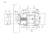
- FIG. 1 is a schematic view illustrating a state in which a safety door lock according to a first embodiment of the present invention is closed
- FIG. 2 is a schematic view illustrating a state in which the safety door lock of FIG. 1 is opened
- FIG. 3 is a perspective view illustrating a state in which a force transmission device according to the first embodiment of the present invention is assembled.
- a door lock includes a force transmission device and handles 1a and 1b installed at a door D.
- the force transmission device includes a body 8 and a latch bolt assembly 80, and may further include a body housing 11.
- the door lock includes the body housing 11 of which both side surfaces are opened in a direction that a through-hole 12 passing through both side surfaces of the door D is formed, the body 8 configured to reciprocate in the body housing 11 by pushing or pulling the handles 1a and 1b and having an inclined surface 15 formed to be slidable with respect to a slider 7, the handles 1a and 1b installed to be connected with the body 8 via the body housing 11 and to protrude outside the both side surfaces of the door D, and the latch bolt assembly 80 interlocked with a reciprocating motion of the body 8, inserted vertically to a lengthwise direction of the body 8 so as to convert a reciprocating direction of the body 8 into a vertical direction, and moved along the lengthwise direction of the body 8.
- the latch bolt assembly 80 includes the slider 7 coupled to one end of a connecting shaft 5 passing through the body 8 to be moved in an axial direction of the connecting shaft 5 while being in contact with the inclined surface having a V-shape groove at the time of a linear motion of the body and to move the connecting shaft 5 in a direction vertical to a moving direction of the body, the connecting shaft 5 installed to be connected with the slider 7 and to linearly reciprocate vertically to the linear reciprocating motion of the body 8, a latch bolt 2 installed at one end of the connecting shaft 5 to be inserted into or separated from a latch bolt insertion groove 16 according to a reciprocating motion of the connecting shaft 5, and an elastic body 6 contracted by a movement of the connecting shaft 5 when an external force is applied in a direction in which the door D is opened, and configured to move and return the connecting shaft 5 in a reverse direction by a returning force when the external force is released.
- the elastic body 6 may be installed at at least one of both ends of the connecting shaft 5 on an outer surface of the body housing 11 to be coupled with the latch bolt 2.
- the first embodiment describes an example in which the elastic body 6 is installed on the outer surface of the body housing 11.
- the elastic body 6 may be installed between an inner surface of the body housing 11 and the inclined surface 15 of the body 8.
- the latch bolt assembly 80 includes a latch case 4 formed to receive the latch bolt 2 in a state of receiving the elastic body 6.
- a body moving space 9 having, for example, an oval or rectangular cross sectional shape vertical to the axial direction of the connecting shaft 5 is formed at a center portion of the body 8, and the connecting shaft 5 reciprocates vertically to the moving direction of the body 8 while being maintained in a state of passing through the body moving space 9. That is, the body moving space 9 means a space in which the body 8 is moved along the connecting shaft 5.
- a connecting shaft guide 17 is formed at the door to prevent shaking of the connecting shaft 5 and to stably reciprocate the connecting shaft 5, when the connecting shaft 5 reciprocates vertically to the moving direction of the body 8.
- the handles 1a and 1b may have a round bar shape, an oval bar shape, or other polygonal shapes, and handles used in the conventional door lock may be used.
- the handles 1a and 1b is assembled to or disassembled from the body 8 through a male screw (not shown) formed in the part toward the body 8 and a female screw (not shown) formed at the body 8.
- shapes, materials, and colors of the handles 1a and 1b may be selected variously in terms of convenience or design, as long as the handles 1a and 1b may push or pull the body 8.
- the body 8 reciprocates along an inner side of the body housing 11 installed inside the through-hole 12 in both directions, and the handle 1a passes through a holder 10, and the holder 10 is fixed to the door D by a holder fixing means 10a.
- the handle performs a complex motion in an up and down direction and a horizontal direction with respect to a door surface, and a reciprocation motion of the handle is transferred to the latch bolt through multiple components, and thus the conventional push-pull door lock has a complicated structure.
- the handle is moved in only one direction vertical to the door surface, and the reciprocating motion of the handle 1a is directly transferred to the latch bolt 2 through the body 8 on which the handle 1a is installed, and thus the number of construction components is small.
- the body housing 11 is installed in the through-hole 12 formed to pass through the both surfaces of the door D and also installed to a predetermined length, such that the body 8 reciprocates along an inner wall of the body housing 11 by the external force which pushes or pulls the handles 1a and 1b.
- the body housing 11 may have various cross sectional shapes such as a circle, an oval, or a polygon. When considering ease of fabrication, it is preferable to have a circular cross sectional shape or a rectangular cross sectional shape.
- the body housing 11 is machined in a " ⁇ "-shape toward an indoor side, and fixed to the door D through a body housing fixing means 11a, and thus the body 8 may easily reciprocate along the inner wall of the body housing 11. Also, disassembling and separating of the door lock at an outdoor side may be prevented and thus a trespass from an outside may be prevented.
- the body 8 linearly reciprocates along the inner wall of the body housing 11 by the external force which pushes or pulls the handles 1a and 1b.
- the connecting shaft 5 reciprocates along the inclined surface 15.
- the inclined surface 15 is formed in a flat surface or a curved surface so that the slider 7 of the latch bolt assembly 80 may be moved in the axial direction of the connecting shaft 5.
- the first embodiment has described an example in which the inclined surface 15 is formed in a V-shaped cut-away groove.
- the connecting shaft 5 of the latch bolt assembly 80 reciprocates between a settling point 18 of the inclined surface 15 forming the V-shaped cut-away groove of the body 8 and two apexes 19, and enables the slider 7 to be continuously in contact with the sliding inclined surface 15 formed at the body 8.
- the sliding inclined surface 15 on which the slider 7 is moved is exposed to an outside, and a moving space of the slider 7 is opened when being seen from a side surface of the body 8.
- the body moving space 9 having the oval or rectangular cross sectional shape vertical to the inclined surface 15 forming the V-shaped cut-away groove and formed vertically to the connecting shaft 5 is formed at the center portion of the body 8 so that the connecting shaft 5 is interlocked with the reciprocating motion of the body 8 and moved vertically to the moving direction of the body 8.
- a width of the body moving space 9 is slightly greater than a diameter of the connecting shaft 5 and a major axis thereof, which is twice or more of a displacement of the latch bolt 2, has the oval or rectangular cross sectional shape, such that the connecting shaft 5 may linearly reciprocate vertically to the linear reciprocating motion of the body 8 while being maintained in a state of passing through the body moving space 9.
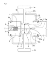
- the inclined surface of the body 8 may be formed in the V-shaped groove, as illustrated in FIGS. 1 and 2 , may be formed in a reversed V-shaped protrusion, as illustrated in FIG. 4 or 6 , or may be formed in a single inclined surface, as illustrated in FIG. 7 .
- the inclined surface 15 is provided in one pair opposite to each other, and it is preferable that one ends thereof are in contact with each other to form a predetermined angle.
- the pair of inclined surfaces may be formed in the V-shaped cut-away groove (referring to FIGS. 1 and 2 ), or may be formed in the reversed V-shaped protrusion (referring to FIGS. 4 and 5 ).
- the angle defined by the pair of inclined surfaces may be 30 to 160°.
- the angle of the sliding inclined surfaces 15 and 15a of the body is reduced, and a height between the settling point (an initial position) and the apexes is increased, the displacement of the connecting shaft with respect to the same moving distance of the body may be increased, and thus the insertion depth of the latch bolt inserted into the latch bolt insertion groove may be deep.
- an inclined surface 15b of FIG. 6 may be formed in the single inclined surface having only one surface. At this time, the single inclined surface may form an angle of 15 to 75°.
- the elastic body having a small elastic force may be used in the door lock mainly used by children or the old and weak, and the elastic body having a large elastic force may be used in the door lock mainly used by adults.
- the body 8 may be machined using a material having various cross sectional shapes such as a board, a rod, a square timber, and a pipe.
- the latch bolt assembly 80 serves to convert the linear reciprocating motion of the body 8 into the vertical reciprocating motion and thus to enable the latch bolt 2 to be inserted into or separated from the latch bolt insertion groove 16.
- the latch bolt assembly 80 includes the connecting shaft 5, the latch bolt 2, the elastic body 6, and the latch case 4, and one end of the connecting shaft 5 is connected with the slider 7, and the other end thereof is connected with the latch bolt 2.
- the latch bolt 2 and a guide bolt 3 are connected with the other end of the connecting shaft 5 to be inserted into or separated from the latch bolt insertion groove 16 according to the reciprocating motion of the connecting shaft 5, and thus to allow the door D to be opened and closed.
- the latch bolt 2 and a guide bolt 3 are received in the latch case 4 together with the connecting shaft 5 and the elastic body 6.
- the latch bolt of the door lock on the market may be inserted into the latch bolt insertion groove 16 in a maximum depth of 15 mm.
- the insertion depth may be adjusted in a depth of 15 mm or more according to the angle of the sliding inclined surface 15 and the moving distance of the body 8.
- the insertion depth of the latch bolt 2 inserted into the latch bolt insertion groove 16 may be deep.
- the safety door lock may be provided.
- the elastic body 6 may be fabricated using a material having elasticity, such as a coil spring, a leaf spring, and rubber.
- connecting shaft guide 17 may be formed at the door to prevent shaking of the connecting shaft 5 and to stably reciprocate the connecting shaft 5, when the connecting shaft 5 reciprocates vertically to the moving direction of the body 8.
- the slider 7 is continuously in contact with the inclined surface 15 and serves to enable the connecting shaft 5 to reciprocate vertically to the reciprocating motion of the body 8.
- a method of connecting the slider 7 with the connecting shaft 5 may include various manners such as a welding. As illustrated in FIG. 3 , when a bolt B and a nut N are used in the connecting method, the insertion length of the latch bolt 2 inserted into the latch bolt insertion groove 16 may be adjusted, as described above.
- the holder 10 serves to protect the body 8 and other construction components from the external force outside the door D and also to prevent separation of the construction components.
- the holder 10 is fixed to the door D by the holder fixing means 10a. Further, the handles 1a and 1b pass through a holder hole 10b formed at a center portion of the holder.
- the body 8 is located at a center portion of the body housing 11, and the slider 7 is located at the settling point 18 of the V-shaped groove of the body 8.
- the latch bolt 2 connected to the connecting shaft 5 protrudes outside the door D and is inserted into the latch bolt insertion groove 16 formed at a strike plate 14, and thus the door D may be maintained in a closed state.
- the body 8 if a user pushes the handle 1a using his/her body such as an arm, the body 8 is moved from the center portion of the body housing 11 to an outside, and the slider 7 is moved up along the sliding inclined surface 15 of the V-shaped groove of the body 8 from the settling point 18 of the body 8 to the apex 19 of the side surface, and thus the connecting shaft 5 connected with the slider 7 is moved toward the connecting shaft guide 17, and the elastic body 6 is contracted. Therefore, the protruding latch bolt 2 is separated from the latch bolt insertion groove 16 and received in the latch case 4.
- the latch bolt of the door lock on the market may be inserted into the latch bolt insertion groove 16 in a maximum depth of 15 mm.
- the insertion depth may be adjusted in a depth of 15 mm or more according to the angle of the sliding inclined surface 15 and the moving distance of the body 8.
- the angle of the body sliding inclined surface 15 formed at the body 8 has the range of 30 to 160°. If the angle of the sliding inclined surface 15 of the body is reduced and the height between the settling point and the apexes is increased, the displacement of the connecting shaft may be increased, and thus the insertion depth of the latch bolt inserted into the latch bolt insertion groove may be deep. Therefore, it is difficult to separate the latch bolt from the latch bolt insertion groove using the tool such as the screw driver, and thus the safety door lock which does not need a double locking device may be provided.
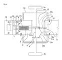
- FIG. 4 is a schematic view illustrating a state in which a safety door lock according to a second embodiment of the present invention is closed
- FIG. 5 is a schematic view illustrating a state in which the safety door lock of FIG. 4 is opened.
- the second embodiment of the present invention has the same configuration and operation as the first embodiment, except a difference in which the sliding inclined surface 15a formed at the body 8 is formed in the reversed V-shape, and thus will be briefly described.
- the body 8 is located at an outer side of the body housing, and the slider 7 is located at a settling point 18a of the body by the elastic force of the elastic body 6, as illustrated in FIG. 4 .
- the latch bolt 2 connected with the slider 7 via the connecting shaft 5 protrudes outside the door D, and is inserted into the latch bolt insertion groove 16 formed at the strike plate 14, and thus the door D is maintained in the closed state.
- the protruding latch bolt 2 is separated from the latch bolt insertion groove 16 and received in the latch case 4. While the latch bolt 2 is received in the latch case 4 as described above, the door D is easily opened by the external force with which the user pushes the door.
- the body 8 is returned to the outside of the body housing, and the slider 7 located at the apex 19a is returned to the settling point 18a along the inclined surface 15a of the body 8, and the latch bolt 2 protrudes to the outside of the door D, and thus the door D is in the locked state.
- FIG. 6 is a schematic view illustrating a state in which a safety door lock according to a third embodiment of the present invention is closed.
- the third embodiment of the present invention has the same configuration and operation as the first and second embodiments, except a difference in which the sliding inclined surface 15b formed at the body 8 is formed in the single inclined surface, and thus will be briefly described.
- each construction component When considering costs, engineering plastics, nonferrous metals, ferrous metals, or the like may be used as a material of each construction component to smoothly perform the above functions and to increase durability thereof, and various fabricating processes may be applied to the construction components.
- the door lock according to the present invention may allow the insertion depth of the latch bolt to be deep, thereby enhancing the safety, and thus persons with physical handicap and reduced mobility, such as disabled persons, patients, and old persons, as well as normal persons may easily open and close the door.
- the fabricating cost is low due to its simple structure, and the present invention may be also installed at the door using the cylindrical or tubular door lock without an additional reconstruction work and may use variously designed handles.
- the first to third embodiments have described an example in which the inclined surface 15 is formed at one side surface of the body 8, but are not limited thereto.
- the inclined surface 15 may be formed in the body 8. That is, the body 8 according to the first to third embodiments has an opened structure in which the inclined surface 15 is exposed to one side surface, and the body 8 according to the fourth to seventh embodiments has an closed structure in which the inclined surface 15 is formed at an inside.
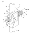
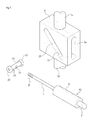
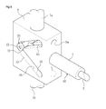
- FIG. 7 is an exploded perspective view illustrating the body 8 and the latch bolt assembly 80 of a closed force transmission device according to the fourth embodiment of the present invention.
- FIG. 8 is a perspective view illustrating a state in which the body 8 and the latch bolt assembly 80 of the closed force transmission device of FIG. 7 are assembled.
- FIGS. 7 and 8 illustrate only the body 8 and latch bolt assembly 80 in the safety door lock according to the fourth embodiment, and the other structures may have the same configurations as those in the safety door lock according to the first to third embodiments.
- the body 8 has the inclined surface 15 formed therein.
- the inclined surface 15 is formed by an inner surface of a linear hole. That is, first and second body moving spaces 9a and 9b as body moving spaces 9a and 9b are formed at the body 8.
- the first body moving space 9a is formed in a slot shape to be parallel with a sliding movement direction in the body housing.
- the second body moving space 9b is formed to be connected with the first body moving space 9a, and formed in the slot shape to be inclined with respect to the sliding movement direction in the body housing, and the inner surface thereof is used as the inclined surface 15.
- the body 8 includes a first surface connected with the first handle 1a, a second surface opposite to the first surface and connected with the second handle 1b, a third surface adjacent to the first and second surfaces, a fourth surface opposite to the third surface, a fifth surface adjacent to the third and fourth surfaces, and a sixth surface opposite to the fifth surface.
- the first body moving space 9a is formed to vertically pass through the third and fourth surfaces, and formed in the slot shape to be parallel with the sliding movement direction in the body housing.
- the second body moving space 9b is formed to pass through the fifth and sixth surfaces, and formed in the slot to be inclined with respect to the sliding movement direction in the body housing, and the inner surface of the second body moving space 9b is used as the inclined surface 15.
- Positions of both ends of the first and second body moving spaces 9a and 9b are formed to be substantially the same, such that the body 8 guides a stable movement of the latch bolt assembly 80.
- the fourth embodiment describes an example in which the second body moving space 9b is formed in a linear shape.
- the body 8 linearly reciprocates along the inner wall of the body housing by the external force which pushes or pulls the handles 1a and 1b.
- the connecting shaft 5 reciprocates between the settling point 18 and the apex 19 of the inclined surface 15 of the body 8, and allows a slider 20 to be continuously in contact with the sliding inclined surface 15 formed at the body 8.
- the settling point 18 and the apex 19 may be located at the both ends of the second body moving space 9b.
- the settling point 18 is located to be adjacent to a latch guide 4.
- the latch bolt assembly 80 includes the slider 20, the connecting shaft 5, the elastic body, and the latch bolt 2. Since the elastic body and the latch bolt 2 installed at the latch guide 4 has the same configurations as those in the first to third embodiments, detailed description thereof will be omitted, and the slider 20 and the connecting shaft 5 will be mainly described.
- the elastic body may be installed at at least one of both ends of the body housing, and may be installed to be coupled with the latch bolt 2.
- the slider 20 is installed at the second body moving space 9b of the body 8, and moved along the second body moving space 9b, and a coupling hole 23 is formed at a portion in which the first and second body moving spaces 9a and 9b are crossed.
- the slider 20 includes a slider rod 21 in which the coupling hole 23 is formed, and one pair of bearings 25 coupled to both ends of the slider rod 21 and moved along the inclined surface 15 of the second body moving space 9b of the body 8.
- the connecting shaft 5 is movably installed to pass through the body 8 and the body housing, and installed to pass through the first body moving space 9a of the body 8.
- the connecting shaft 5 is coupled and fixed into the coupling hole 23 of the slider 20.
- the safety door lock according to the fourth embodiment as described above is operated as follows. That is, if the handles 1a and 1b are pushed or pulled, the slider 20 is moved along the inclined surface 15, and interlockingly moves the latch bolt 2 to an inner sider of the latch guide 4. And if the force which pushes or pulls the handles 1a and 1b is released, the latch bolt 2 protrudes outside the latch guide 4 due to the elastic force of the elastic body installed at the latch guide 4. That is, the safety door lock according to the fourth embodiment is operated in the same manner as that according to the third embodiment, except that the inclined surface 15 is formed in the body 8.
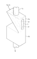
- the fourth embodiment has described an example in which the second body moving space 9b is formed in the linear shape, but is not limited thereto.
- the second body moving space 9b may have at least one curved portion. That is, as illustrated in FIG. 9 , the second body moving space 9b of the safety door lock according to the fifth embodiment is formed by an inner surface of a V-shaped hole.
- the body 8 linearly reciprocates along the inner wall of the body housing by the external force which pushes or pulls the handles 1a and 1b.
- the connecting shaft 5 reciprocates between the settling point 18 and two apexes 19 of the V-shaped inclined surface 15 of the body 8, and allows the slider 20 to be continuously in contact with the sliding inclined surface 15 formed at the body 8.
- the settling point 18 may be located at a valley portion of the V-shaped inclined surface 15, and the apexes may be located at both ends of the V-shaped inclined surface 15.
- a protruding portion of the second body moving space 9b is formed at a side distant from a surface at which the latch guide 4 is installed, but may be formed at a reverse side adjacent to the surface, like the first embodiment.
- the safety door lock according to the fifth embodiment is operated in the same manner as that according to the second embodiment, except that the inclined surface 15 is formed in the body 8.
- each body 8 of the safety door locks according to the third and fourth embodiments as described above may be modified into a body 8 as illustrated in FIGS. 10 and 11 . That is, referring to FIG. 10 , a safety door lock according to a sixth embodiment may be used in only one direction using the handles 1a and 1b, and may include a subsidiary body 8b configured to install the handles 1a and 1b to be symmetrical to each other with respect to the body 8.
- the body 8 may include a main body 8a in which the body moving space 9 is formed, and the subsidiary body 8b connected with the main body 8a.
- the first handle 1a may be connected with the main body 8a, and the second handle 1b may be connected with the subsidiary body 8b.
- the settling point 18 and the apex 19 may be located at the both ends of the body moving space 9.
- the settling point 18 is installed to a side adjacent to the latch guide. That is, the settling point 18 is installed to a side adjacent to a portion connected with the subsidiary body 8b.
- a safety door lock according to a seventh embodiment may be used in only one direction using the handles 1a and 1b, and may include a subsidiary body 8b configured to install the handles 1a and 1b to be symmetrical to each other with respect to the body 8.
- the body 8 may include a main body 8a in which the body moving spaces 9a and 9b are formed, and the subsidiary body 8b connected with the main body 8a.
- the first handle 1a may be connected with the main body 8a, and the second handle 1b may be connected with the subsidiary body 8b.
- the settling point 18 and the apex 19 may be located at the both ends of the second body moving space 9b.
- the settling point 18 is installed to the side adjacent to the latch guide. That is, the settling point 18 is installed to a side adjacent to a portion connected with the subsidiary body 8b.
Landscapes
- Engineering & Computer Science (AREA)
- Mechanical Engineering (AREA)
- Structural Engineering (AREA)
- Lock And Its Accessories (AREA)
Applications Claiming Priority (2)
| Application Number | Priority Date | Filing Date | Title |
|---|---|---|---|
| KR1020120019232A KR101327412B1 (ko) | 2012-02-24 | 2012-02-24 | 폐쇄형 힘 전달기구 및 그를 이용한 안전 도어록 |
| PCT/KR2012/001874 WO2013125746A1 (ko) | 2012-02-24 | 2012-03-15 | 폐쇄형 힘 전달기구 및 그를 이용한 안전 도어록 |
Publications (3)
| Publication Number | Publication Date |
|---|---|
| EP2818613A1 true EP2818613A1 (de) | 2014-12-31 |
| EP2818613A4 EP2818613A4 (de) | 2016-05-18 |
| EP2818613B1 EP2818613B1 (de) | 2018-11-28 |
Family
ID=49005911
Family Applications (1)
| Application Number | Title | Priority Date | Filing Date |
|---|---|---|---|
| EP12869289.4A Not-in-force EP2818613B1 (de) | 2012-02-24 | 2012-03-15 | Geschlossene kraftübertragungsvorrichtung und sicherheitstürschloss damit |
Country Status (8)
| Country | Link |
|---|---|
| US (1) | US9771745B2 (de) |
| EP (1) | EP2818613B1 (de) |
| JP (1) | JP5969055B2 (de) |
| KR (1) | KR101327412B1 (de) |
| CN (1) | CN104169508B (de) |
| AU (1) | AU2012370602B2 (de) |
| IN (1) | IN2014KN01760A (de) |
| WO (1) | WO2013125746A1 (de) |
Families Citing this family (8)
| Publication number | Priority date | Publication date | Assignee | Title |
|---|---|---|---|---|
| CN103038083B (zh) * | 2010-05-28 | 2016-11-16 | 凯毅德股份公司 | 用于机车的致动驱动器 |
| BR112013004047A2 (pt) * | 2010-08-27 | 2019-11-26 | Hee Kim Young | mecanismo de trasferência de força |
| WO2016033804A1 (en) * | 2014-09-05 | 2016-03-10 | Hampton Products International Corporation | Handle set having latch bolt actuable by pushing handle |
| KR101740621B1 (ko) | 2015-09-24 | 2017-05-29 | 김영희 | 힘 전달 장치 |
| TWI817974B (zh) | 2017-12-28 | 2023-10-11 | 日商中外製藥股份有限公司 | 細胞毒性誘導治療劑 |
| DE102019100398A1 (de) * | 2019-01-09 | 2020-07-09 | Emka Beschlagteile Gmbh & Co. Kg | Befestigungsvorrichtung |
| KR102144784B1 (ko) * | 2019-01-22 | 2020-08-18 | 주식회사 우보테크 | 차량 도어용 플러시 핸들 |
| KR102254176B1 (ko) * | 2020-12-01 | 2021-05-21 | 이규민 | 마그네틱을 갖는 개폐장치가 구비되는 양 방향 도어 |
Family Cites Families (24)
| Publication number | Priority date | Publication date | Assignee | Title |
|---|---|---|---|---|
| US823174A (en) * | 1905-06-07 | 1906-06-12 | John Jorgenson | Lock. |
| US980630A (en) * | 1910-04-29 | 1911-01-03 | Edson Granger | Combined lock and latch. |
| US1021864A (en) * | 1911-01-27 | 1912-04-02 | Carl Denzler | Lock. |
| US1209924A (en) * | 1916-05-16 | 1916-12-26 | Cashus Elwood Ackley | Door-lock. |
| US2036154A (en) * | 1935-05-02 | 1936-03-31 | Hickson F Littledale | Combined latch and lock structure |
| CH225523A (de) * | 1942-03-20 | 1943-02-15 | Finger Franz | Türschloss. |
| US2726889A (en) * | 1952-07-24 | 1955-12-13 | Melpar Inc | Latch |
| US2960858A (en) * | 1956-10-08 | 1960-11-22 | Webster Desmond Edward Charles | Closure fastening device |
| US3385622A (en) * | 1966-05-16 | 1968-05-28 | Lorin D. Winger | Latch and lock mechanism |
| US3490803A (en) * | 1967-01-03 | 1970-01-20 | Henry W Rollins | Door lock construction |
| US3582121A (en) * | 1969-09-26 | 1971-06-01 | Henry W Rollins | Control for door lock set |
| JPS5427900A (en) * | 1977-07-30 | 1979-03-02 | Matsushita Electric Works Ltd | Apparatus for releasing door lock |
| JPH0450377Y2 (de) * | 1987-01-17 | 1992-11-27 | ||
| JPS63136177U (de) * | 1987-02-26 | 1988-09-07 | ||
| US5026101A (en) * | 1990-04-27 | 1991-06-25 | Dotterweich John E | Push-pull or twist door knob/handle mechanism |
| US5947535A (en) * | 1996-10-18 | 1999-09-07 | Baker; John R. | Dual motion, quick release latch mechanism |
| KR200160871Y1 (en) | 1997-06-12 | 1999-11-15 | Park Seong Hwn | The door lock structure movable from the front to the rear |
| KR200184812Y1 (ko) * | 1997-06-20 | 2000-06-01 | 손영수 | 개량 도어록 |
| KR100247234B1 (ko) * | 1997-08-30 | 2000-03-15 | 천강월 | 도어록크 |
| KR20000074623A (ko) * | 1999-05-24 | 2000-12-15 | 이병국 | 푸시-풀 타입 도어 개폐장치 |
| CN2533222Y (zh) * | 2002-03-29 | 2003-01-29 | 台湾福兴工业股份有限公司 | 平把锁的内侧上锁装置 |
| KR100943543B1 (ko) * | 2009-04-22 | 2010-02-22 | 윤병만 | 안전형 도어록 장치 |
| KR101185769B1 (ko) | 2010-09-07 | 2012-10-02 | 김영희 | 안전 도어록 |
| KR101293221B1 (ko) * | 2013-02-08 | 2013-08-08 | 송건회 | 도어록 장치 |
-
2012
- 2012-02-24 KR KR1020120019232A patent/KR101327412B1/ko not_active Expired - Fee Related
- 2012-03-15 EP EP12869289.4A patent/EP2818613B1/de not_active Not-in-force
- 2012-03-15 AU AU2012370602A patent/AU2012370602B2/en not_active Ceased
- 2012-03-15 JP JP2014558658A patent/JP5969055B2/ja not_active Expired - Fee Related
- 2012-03-15 CN CN201280070621.6A patent/CN104169508B/zh not_active Expired - Fee Related
- 2012-03-15 US US14/379,929 patent/US9771745B2/en not_active Expired - Fee Related
- 2012-03-15 WO PCT/KR2012/001874 patent/WO2013125746A1/ko not_active Ceased
-
2014
- 2014-08-21 IN IN1760KON2014 patent/IN2014KN01760A/en unknown
Also Published As
| Publication number | Publication date |
|---|---|
| KR20130097514A (ko) | 2013-09-03 |
| EP2818613B1 (de) | 2018-11-28 |
| KR101327412B1 (ko) | 2013-11-08 |
| AU2012370602A1 (en) | 2014-09-25 |
| JP2015511285A (ja) | 2015-04-16 |
| WO2013125746A1 (ko) | 2013-08-29 |
| JP5969055B2 (ja) | 2016-08-10 |
| US9771745B2 (en) | 2017-09-26 |
| AU2012370602B2 (en) | 2015-12-17 |
| CN104169508B (zh) | 2016-06-08 |
| US20150042106A1 (en) | 2015-02-12 |
| CN104169508A (zh) | 2014-11-26 |
| IN2014KN01760A (de) | 2015-10-23 |
| EP2818613A4 (de) | 2016-05-18 |
Similar Documents
| Publication | Publication Date | Title |
|---|---|---|
| EP2818613B1 (de) | Geschlossene kraftübertragungsvorrichtung und sicherheitstürschloss damit | |
| KR101185769B1 (ko) | 안전 도어록 | |
| US8813298B2 (en) | Cleaning tool and stick-like tool | |
| US9103419B2 (en) | Radially engaging system | |
| KR200469274Y1 (ko) | 클러치 연결이 용이한 전자식 문 잠금장치 | |
| US20210214967A1 (en) | Deadbolt assembly | |
| US11458359B2 (en) | Chest expander | |
| CA3128623C (en) | Transmission mechanism and lock | |
| KR101666764B1 (ko) | 푸시풀형 도어락 | |
| CN111734238A (zh) | 一种按钮式机柜门锁结构及机柜门 | |
| CN109398294B (zh) | 一种安全带高度调节器 | |
| CN102016205A (zh) | 锁定机构闭锁装置 | |
| CN107386779B (zh) | 一种中心锁及帐篷 | |
| US11686122B2 (en) | Transmission mechanism and lock | |
| JP4832977B2 (ja) | 家具の脚体の上下伸縮構造 | |
| CN212224956U (zh) | 一种按钮式机柜门锁结构及机柜门 | |
| CN217060872U (zh) | 一种锁紧机构及电子设备 | |
| CN116084780B (zh) | 一种门磁吸锁和玻璃房门 | |
| CN217999218U (zh) | 防猫眼开锁锁具 | |
| JP2008127857A (ja) | 引戸用ロック具及びこれを利用した引戸錠 | |
| CN117215063A (zh) | 位置调节机构及头戴设备 |
Legal Events
| Date | Code | Title | Description |
|---|---|---|---|
| PUAI | Public reference made under article 153(3) epc to a published international application that has entered the european phase |
Free format text: ORIGINAL CODE: 0009012 |
|
| 17P | Request for examination filed |
Effective date: 20140904 |
|
| AK | Designated contracting states |
Kind code of ref document: A1 Designated state(s): AL AT BE BG CH CY CZ DE DK EE ES FI FR GB GR HR HU IE IS IT LI LT LU LV MC MK MT NL NO PL PT RO RS SE SI SK SM TR |
|
| AX | Request for extension of the european patent |
Extension state: BA ME |
|
| DAX | Request for extension of the european patent (deleted) | ||
| REG | Reference to a national code |
Ref country code: DE Ref legal event code: R079 Ref document number: 602012054203 Country of ref document: DE Free format text: PREVIOUS MAIN CLASS: E05B0055140000 Ipc: E05C0001140000 |
|
| RA4 | Supplementary search report drawn up and despatched (corrected) |
Effective date: 20160420 |
|
| RIC1 | Information provided on ipc code assigned before grant |
Ipc: E05B 63/06 20060101ALI20160414BHEP Ipc: E05C 1/14 20060101AFI20160414BHEP |
|
| STAA | Information on the status of an ep patent application or granted ep patent |
Free format text: STATUS: EXAMINATION IS IN PROGRESS |
|
| 17Q | First examination report despatched |
Effective date: 20170614 |
|
| GRAP | Despatch of communication of intention to grant a patent |
Free format text: ORIGINAL CODE: EPIDOSNIGR1 |
|
| STAA | Information on the status of an ep patent application or granted ep patent |
Free format text: STATUS: GRANT OF PATENT IS INTENDED |
|
| INTG | Intention to grant announced |
Effective date: 20180605 |
|
| GRAS | Grant fee paid |
Free format text: ORIGINAL CODE: EPIDOSNIGR3 |
|
| GRAA | (expected) grant |
Free format text: ORIGINAL CODE: 0009210 |
|
| STAA | Information on the status of an ep patent application or granted ep patent |
Free format text: STATUS: THE PATENT HAS BEEN GRANTED |
|
| AK | Designated contracting states |
Kind code of ref document: B1 Designated state(s): AL AT BE BG CH CY CZ DE DK EE ES FI FR GB GR HR HU IE IS IT LI LT LU LV MC MK MT NL NO PL PT RO RS SE SI SK SM TR |
|
| REG | Reference to a national code |
Ref country code: GB Ref legal event code: FG4D |
|
| REG | Reference to a national code |
Ref country code: CH Ref legal event code: EP |
|
| REG | Reference to a national code |
Ref country code: AT Ref legal event code: REF Ref document number: 1070432 Country of ref document: AT Kind code of ref document: T Effective date: 20181215 |
|
| REG | Reference to a national code |
Ref country code: DE Ref legal event code: R096 Ref document number: 602012054203 Country of ref document: DE |
|
| REG | Reference to a national code |
Ref country code: IE Ref legal event code: FG4D |
|
| REG | Reference to a national code |
Ref country code: NL Ref legal event code: MP Effective date: 20181128 |
|
| REG | Reference to a national code |
Ref country code: LT Ref legal event code: MG4D |
|
| REG | Reference to a national code |
Ref country code: AT Ref legal event code: MK05 Ref document number: 1070432 Country of ref document: AT Kind code of ref document: T Effective date: 20181128 |
|
| PG25 | Lapsed in a contracting state [announced via postgrant information from national office to epo] |
Ref country code: IS Free format text: LAPSE BECAUSE OF FAILURE TO SUBMIT A TRANSLATION OF THE DESCRIPTION OR TO PAY THE FEE WITHIN THE PRESCRIBED TIME-LIMIT Effective date: 20190328 Ref country code: FI Free format text: LAPSE BECAUSE OF FAILURE TO SUBMIT A TRANSLATION OF THE DESCRIPTION OR TO PAY THE FEE WITHIN THE PRESCRIBED TIME-LIMIT Effective date: 20181128 Ref country code: NO Free format text: LAPSE BECAUSE OF FAILURE TO SUBMIT A TRANSLATION OF THE DESCRIPTION OR TO PAY THE FEE WITHIN THE PRESCRIBED TIME-LIMIT Effective date: 20190228 Ref country code: LT Free format text: LAPSE BECAUSE OF FAILURE TO SUBMIT A TRANSLATION OF THE DESCRIPTION OR TO PAY THE FEE WITHIN THE PRESCRIBED TIME-LIMIT Effective date: 20181128 Ref country code: HR Free format text: LAPSE BECAUSE OF FAILURE TO SUBMIT A TRANSLATION OF THE DESCRIPTION OR TO PAY THE FEE WITHIN THE PRESCRIBED TIME-LIMIT Effective date: 20181128 Ref country code: BG Free format text: LAPSE BECAUSE OF FAILURE TO SUBMIT A TRANSLATION OF THE DESCRIPTION OR TO PAY THE FEE WITHIN THE PRESCRIBED TIME-LIMIT Effective date: 20190228 Ref country code: ES Free format text: LAPSE BECAUSE OF FAILURE TO SUBMIT A TRANSLATION OF THE DESCRIPTION OR TO PAY THE FEE WITHIN THE PRESCRIBED TIME-LIMIT Effective date: 20181128 Ref country code: AT Free format text: LAPSE BECAUSE OF FAILURE TO SUBMIT A TRANSLATION OF THE DESCRIPTION OR TO PAY THE FEE WITHIN THE PRESCRIBED TIME-LIMIT Effective date: 20181128 Ref country code: LV Free format text: LAPSE BECAUSE OF FAILURE TO SUBMIT A TRANSLATION OF THE DESCRIPTION OR TO PAY THE FEE WITHIN THE PRESCRIBED TIME-LIMIT Effective date: 20181128 |
|
| PG25 | Lapsed in a contracting state [announced via postgrant information from national office to epo] |
Ref country code: PT Free format text: LAPSE BECAUSE OF FAILURE TO SUBMIT A TRANSLATION OF THE DESCRIPTION OR TO PAY THE FEE WITHIN THE PRESCRIBED TIME-LIMIT Effective date: 20190328 Ref country code: AL Free format text: LAPSE BECAUSE OF FAILURE TO SUBMIT A TRANSLATION OF THE DESCRIPTION OR TO PAY THE FEE WITHIN THE PRESCRIBED TIME-LIMIT Effective date: 20181128 Ref country code: GR Free format text: LAPSE BECAUSE OF FAILURE TO SUBMIT A TRANSLATION OF THE DESCRIPTION OR TO PAY THE FEE WITHIN THE PRESCRIBED TIME-LIMIT Effective date: 20190301 Ref country code: RS Free format text: LAPSE BECAUSE OF FAILURE TO SUBMIT A TRANSLATION OF THE DESCRIPTION OR TO PAY THE FEE WITHIN THE PRESCRIBED TIME-LIMIT Effective date: 20181128 Ref country code: SE Free format text: LAPSE BECAUSE OF FAILURE TO SUBMIT A TRANSLATION OF THE DESCRIPTION OR TO PAY THE FEE WITHIN THE PRESCRIBED TIME-LIMIT Effective date: 20181128 |
|
| PG25 | Lapsed in a contracting state [announced via postgrant information from national office to epo] |
Ref country code: NL Free format text: LAPSE BECAUSE OF FAILURE TO SUBMIT A TRANSLATION OF THE DESCRIPTION OR TO PAY THE FEE WITHIN THE PRESCRIBED TIME-LIMIT Effective date: 20181128 |
|
| PG25 | Lapsed in a contracting state [announced via postgrant information from national office to epo] |
Ref country code: IT Free format text: LAPSE BECAUSE OF FAILURE TO SUBMIT A TRANSLATION OF THE DESCRIPTION OR TO PAY THE FEE WITHIN THE PRESCRIBED TIME-LIMIT Effective date: 20181128 Ref country code: CZ Free format text: LAPSE BECAUSE OF FAILURE TO SUBMIT A TRANSLATION OF THE DESCRIPTION OR TO PAY THE FEE WITHIN THE PRESCRIBED TIME-LIMIT Effective date: 20181128 Ref country code: DK Free format text: LAPSE BECAUSE OF FAILURE TO SUBMIT A TRANSLATION OF THE DESCRIPTION OR TO PAY THE FEE WITHIN THE PRESCRIBED TIME-LIMIT Effective date: 20181128 Ref country code: PL Free format text: LAPSE BECAUSE OF FAILURE TO SUBMIT A TRANSLATION OF THE DESCRIPTION OR TO PAY THE FEE WITHIN THE PRESCRIBED TIME-LIMIT Effective date: 20181128 |
|
| REG | Reference to a national code |
Ref country code: DE Ref legal event code: R097 Ref document number: 602012054203 Country of ref document: DE |
|
| PG25 | Lapsed in a contracting state [announced via postgrant information from national office to epo] |
Ref country code: SK Free format text: LAPSE BECAUSE OF FAILURE TO SUBMIT A TRANSLATION OF THE DESCRIPTION OR TO PAY THE FEE WITHIN THE PRESCRIBED TIME-LIMIT Effective date: 20181128 Ref country code: RO Free format text: LAPSE BECAUSE OF FAILURE TO SUBMIT A TRANSLATION OF THE DESCRIPTION OR TO PAY THE FEE WITHIN THE PRESCRIBED TIME-LIMIT Effective date: 20181128 Ref country code: EE Free format text: LAPSE BECAUSE OF FAILURE TO SUBMIT A TRANSLATION OF THE DESCRIPTION OR TO PAY THE FEE WITHIN THE PRESCRIBED TIME-LIMIT Effective date: 20181128 Ref country code: SM Free format text: LAPSE BECAUSE OF FAILURE TO SUBMIT A TRANSLATION OF THE DESCRIPTION OR TO PAY THE FEE WITHIN THE PRESCRIBED TIME-LIMIT Effective date: 20181128 |
|
| PLBE | No opposition filed within time limit |
Free format text: ORIGINAL CODE: 0009261 |
|
| STAA | Information on the status of an ep patent application or granted ep patent |
Free format text: STATUS: NO OPPOSITION FILED WITHIN TIME LIMIT |
|
| PG25 | Lapsed in a contracting state [announced via postgrant information from national office to epo] |
Ref country code: SI Free format text: LAPSE BECAUSE OF FAILURE TO SUBMIT A TRANSLATION OF THE DESCRIPTION OR TO PAY THE FEE WITHIN THE PRESCRIBED TIME-LIMIT Effective date: 20181128 Ref country code: MC Free format text: LAPSE BECAUSE OF FAILURE TO SUBMIT A TRANSLATION OF THE DESCRIPTION OR TO PAY THE FEE WITHIN THE PRESCRIBED TIME-LIMIT Effective date: 20181128 |
|
| REG | Reference to a national code |
Ref country code: CH Ref legal event code: PL |
|
| 26N | No opposition filed |
Effective date: 20190829 |
|
| PG25 | Lapsed in a contracting state [announced via postgrant information from national office to epo] |
Ref country code: LU Free format text: LAPSE BECAUSE OF NON-PAYMENT OF DUE FEES Effective date: 20190315 |
|
| REG | Reference to a national code |
Ref country code: BE Ref legal event code: MM Effective date: 20190331 |
|
| PG25 | Lapsed in a contracting state [announced via postgrant information from national office to epo] |
Ref country code: LI Free format text: LAPSE BECAUSE OF NON-PAYMENT OF DUE FEES Effective date: 20190331 Ref country code: IE Free format text: LAPSE BECAUSE OF NON-PAYMENT OF DUE FEES Effective date: 20190315 Ref country code: CH Free format text: LAPSE BECAUSE OF NON-PAYMENT OF DUE FEES Effective date: 20190331 |
|
| PG25 | Lapsed in a contracting state [announced via postgrant information from national office to epo] |
Ref country code: BE Free format text: LAPSE BECAUSE OF NON-PAYMENT OF DUE FEES Effective date: 20190331 |
|
| PG25 | Lapsed in a contracting state [announced via postgrant information from national office to epo] |
Ref country code: TR Free format text: LAPSE BECAUSE OF FAILURE TO SUBMIT A TRANSLATION OF THE DESCRIPTION OR TO PAY THE FEE WITHIN THE PRESCRIBED TIME-LIMIT Effective date: 20181128 |
|
| PG25 | Lapsed in a contracting state [announced via postgrant information from national office to epo] |
Ref country code: MT Free format text: LAPSE BECAUSE OF NON-PAYMENT OF DUE FEES Effective date: 20190315 |
|
| PGFP | Annual fee paid to national office [announced via postgrant information from national office to epo] |
Ref country code: FR Payment date: 20210323 Year of fee payment: 10 |
|
| PG25 | Lapsed in a contracting state [announced via postgrant information from national office to epo] |
Ref country code: CY Free format text: LAPSE BECAUSE OF FAILURE TO SUBMIT A TRANSLATION OF THE DESCRIPTION OR TO PAY THE FEE WITHIN THE PRESCRIBED TIME-LIMIT Effective date: 20181128 |
|
| PGFP | Annual fee paid to national office [announced via postgrant information from national office to epo] |
Ref country code: GB Payment date: 20210324 Year of fee payment: 10 |
|
| PG25 | Lapsed in a contracting state [announced via postgrant information from national office to epo] |
Ref country code: HU Free format text: LAPSE BECAUSE OF FAILURE TO SUBMIT A TRANSLATION OF THE DESCRIPTION OR TO PAY THE FEE WITHIN THE PRESCRIBED TIME-LIMIT; INVALID AB INITIO Effective date: 20120315 |
|
| PGFP | Annual fee paid to national office [announced via postgrant information from national office to epo] |
Ref country code: DE Payment date: 20210331 Year of fee payment: 10 |
|
| PG25 | Lapsed in a contracting state [announced via postgrant information from national office to epo] |
Ref country code: MK Free format text: LAPSE BECAUSE OF FAILURE TO SUBMIT A TRANSLATION OF THE DESCRIPTION OR TO PAY THE FEE WITHIN THE PRESCRIBED TIME-LIMIT Effective date: 20181128 |
|
| REG | Reference to a national code |
Ref country code: DE Ref legal event code: R119 Ref document number: 602012054203 Country of ref document: DE |
|
| GBPC | Gb: european patent ceased through non-payment of renewal fee |
Effective date: 20220315 |
|
| PG25 | Lapsed in a contracting state [announced via postgrant information from national office to epo] |
Ref country code: GB Free format text: LAPSE BECAUSE OF NON-PAYMENT OF DUE FEES Effective date: 20220315 Ref country code: FR Free format text: LAPSE BECAUSE OF NON-PAYMENT OF DUE FEES Effective date: 20220331 Ref country code: DE Free format text: LAPSE BECAUSE OF NON-PAYMENT OF DUE FEES Effective date: 20221001 |