EP2818613B1 - Geschlossene kraftübertragungsvorrichtung und sicherheitstürschloss damit - Google Patents
Geschlossene kraftübertragungsvorrichtung und sicherheitstürschloss damit Download PDFInfo
- Publication number
- EP2818613B1 EP2818613B1 EP12869289.4A EP12869289A EP2818613B1 EP 2818613 B1 EP2818613 B1 EP 2818613B1 EP 12869289 A EP12869289 A EP 12869289A EP 2818613 B1 EP2818613 B1 EP 2818613B1
- Authority
- EP
- European Patent Office
- Prior art keywords
- door lock
- latch bolt
- moving space
- connecting shaft
- inclined surface
- Prior art date
- Legal status (The legal status is an assumption and is not a legal conclusion. Google has not performed a legal analysis and makes no representation as to the accuracy of the status listed.)
- Not-in-force
Links
- 230000005540 biological transmission Effects 0.000 title description 14
- 230000033001 locomotion Effects 0.000 claims description 26
- 230000008878 coupling Effects 0.000 claims description 9
- 238000010168 coupling process Methods 0.000 claims description 9
- 238000005859 coupling reaction Methods 0.000 claims description 9
- 238000006073 displacement reaction Methods 0.000 claims description 7
- 238000003780 insertion Methods 0.000 description 39
- 230000037431 insertion Effects 0.000 description 39
- 238000010276 construction Methods 0.000 description 8
- 230000001965 increasing effect Effects 0.000 description 8
- 238000000034 method Methods 0.000 description 6
- 239000000463 material Substances 0.000 description 4
- 239000003086 colorant Substances 0.000 description 2
- 230000002708 enhancing effect Effects 0.000 description 2
- 238000004519 manufacturing process Methods 0.000 description 2
- 229910052751 metal Inorganic materials 0.000 description 2
- 239000002184 metal Substances 0.000 description 2
- 230000001419 dependent effect Effects 0.000 description 1
- 230000000694 effects Effects 0.000 description 1
- 229920006351 engineering plastic Polymers 0.000 description 1
- -1 ferrous metals Chemical class 0.000 description 1
- 150000002739 metals Chemical class 0.000 description 1
- 238000012986 modification Methods 0.000 description 1
- 230000004048 modification Effects 0.000 description 1
- 238000000926 separation method Methods 0.000 description 1
- 238000003466 welding Methods 0.000 description 1
Images


Classifications
-
- E—FIXED CONSTRUCTIONS
- E05—LOCKS; KEYS; WINDOW OR DOOR FITTINGS; SAFES
- E05B—LOCKS; ACCESSORIES THEREFOR; HANDCUFFS
- E05B55/00—Locks in which a sliding latch is used also as a locking bolt
-
- E—FIXED CONSTRUCTIONS
- E05—LOCKS; KEYS; WINDOW OR DOOR FITTINGS; SAFES
- E05C—BOLTS OR FASTENING DEVICES FOR WINGS, SPECIALLY FOR DOORS OR WINDOWS
- E05C1/00—Fastening devices with bolts moving rectilinearly
- E05C1/08—Fastening devices with bolts moving rectilinearly with latching action
- E05C1/12—Fastening devices with bolts moving rectilinearly with latching action with operating handle or equivalent member moving otherwise than rigidly with the latch
- E05C1/14—Fastening devices with bolts moving rectilinearly with latching action with operating handle or equivalent member moving otherwise than rigidly with the latch the handle or member moving essentially towards or away from the plane of the wing or frame
-
- E—FIXED CONSTRUCTIONS
- E05—LOCKS; KEYS; WINDOW OR DOOR FITTINGS; SAFES
- E05B—LOCKS; ACCESSORIES THEREFOR; HANDCUFFS
- E05B59/00—Locks with latches separate from the lock-bolts or with a plurality of latches or lock-bolts
-
- E—FIXED CONSTRUCTIONS
- E05—LOCKS; KEYS; WINDOW OR DOOR FITTINGS; SAFES
- E05B—LOCKS; ACCESSORIES THEREFOR; HANDCUFFS
- E05B63/00—Locks or fastenings with special structural characteristics
- E05B63/06—Locks or fastenings with special structural characteristics with lengthwise-adjustable bolts ; with adjustable backset, i.e. distance from door edge
-
- E—FIXED CONSTRUCTIONS
- E05—LOCKS; KEYS; WINDOW OR DOOR FITTINGS; SAFES
- E05C—BOLTS OR FASTENING DEVICES FOR WINGS, SPECIALLY FOR DOORS OR WINDOWS
- E05C1/00—Fastening devices with bolts moving rectilinearly
- E05C1/08—Fastening devices with bolts moving rectilinearly with latching action
- E05C1/12—Fastening devices with bolts moving rectilinearly with latching action with operating handle or equivalent member moving otherwise than rigidly with the latch
-
- Y—GENERAL TAGGING OF NEW TECHNOLOGICAL DEVELOPMENTS; GENERAL TAGGING OF CROSS-SECTIONAL TECHNOLOGIES SPANNING OVER SEVERAL SECTIONS OF THE IPC; TECHNICAL SUBJECTS COVERED BY FORMER USPC CROSS-REFERENCE ART COLLECTIONS [XRACs] AND DIGESTS
- Y10—TECHNICAL SUBJECTS COVERED BY FORMER USPC
- Y10T—TECHNICAL SUBJECTS COVERED BY FORMER US CLASSIFICATION
- Y10T292/00—Closure fasteners
- Y10T292/08—Bolts
- Y10T292/096—Sliding
Definitions
- the insertion depth of the latch bolt inserted into the latch bolt insertion groove may not be increased beyond a predetermined depth, it has low safety, and thus the double locking device may be required.
- the inclined surface may be formed into a single inclined surface or one pair of inclined surfaces opposed to each other, and one ends thereof may be in contact with each other to form a predetermined angle.
- the pair of inclined surfaces may be formed in a V-shaped cut-away groove or a reversed V-shaped protrusion.
- a portion of the slider, which is in contact with the inclined surface, may be formed in an arc shape.
- the second body moving space is formed in a linear shape.
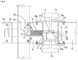
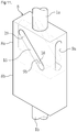
- FIG. 1 is a schematic view illustrating a state in which a safety door lock according to a first embodiment which is not part of the present invention is closed
- FIG. 2 is a schematic view illustrating a state in which the safety door lock of FIG. 1 is opened
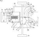
- FIG. 3 is a perspective view illustrating a state in which a force transmission device according to the first embodiment is assembled.
- a door lock includes a force transmission device and handles 1a and 1b installed at a door D.
- the force transmission device includes a body 8 and a latch bolt assembly 80, and may further include a body housing 11.
- the door lock includes the body housing 11 of which both side surfaces are opened in a direction that a through-hole 12 passing through both side surfaces of the door D is formed, the body 8 configured to reciprocate in the body housing 11 by pushing or pulling the handles 1a and 1b and having an inclined surface 15 formed to be slidable with respect to a slider 7, the handles 1a and 1b installed to be connected with the body 8 via the body housing 11 and to protrude outside the both side surfaces of the door D, and the latch bolt assembly 80 interlocked with a reciprocating motion of the body 8, inserted vertically to a lengthwise direction of the body 8 so as to convert a reciprocating direction of the body 8 into a vertical direction, and moved along the lengthwise direction of the body 8.
- the sliding inclined surface 15 on which the slider 7 is moved is exposed to an outside, and a moving space of the slider 7 is opened when being seen from a side surface of the body 8.
- the body moving space 9 having the oval or rectangular cross sectional shape vertical to the inclined surface 15 forming the V-shaped cut-away groove and formed vertically to the connecting shaft 5 is formed at the center portion of the body 8 so that the connecting shaft 5 is interlocked with the reciprocating motion of the body 8 and moved vertically to the moving direction of the body 8.
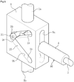
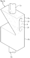
- FIG. 7 is an exploded perspective view illustrating the body 8 and the latch bolt assembly 80 of a closed force transmission device according to the fourth embodiment of the present invention.
- FIG. 8 is a perspective view illustrating a state in which the body 8 and the latch bolt assembly 80 of the closed force transmission device of FIG. 7 are assembled.
- FIGS. 7 and 8 illustrate only the body 8 and latch bolt assembly 80 in the safety door lock according to the fourth embodiment, and the other structures may have the same configurations as those in the safety door lock according to the first to third embodiments.
- the settling point 18 and the apex 19 may be located at the both ends of the body moving space 9.
- the settling point 18 is installed to a side adjacent to the latch guide. That is, the settling point 18 is installed to a side adjacent to a portion connected with the subsidiary body 8b.
Landscapes
- Engineering & Computer Science (AREA)
- Mechanical Engineering (AREA)
- Structural Engineering (AREA)
- Lock And Its Accessories (AREA)
Claims (13)
- Geschlossenes Sicherheitstürschloss, mit:einem Körpergehäuse (11), von welchem beide Seitenflächen in einer Zylinderform geöffnet sind, um durch eine Tür (D) zu führen;einem Körper (8), der in dem Körpergehäuse (11) verschiebbar angebracht ist, um durch eine äußere Kraft geradlinig bewegt zu sein und der mindestens eine geneigte Fläche (15) und einen Körperbewegungsraum (9) hat, der an einer mit der geneigten Fläche (15) übereinstimmenden Position ausgebildet ist, um senkrecht zu der geradlinigen Bewegungsrichtung zu sein;Griffen (1a, 1b), die mit dem Körper (8) durch das Körpergehäuse (11) verbunden sind, um jeweils von beiden Seitenflächen der Tür (D) nach draußen vorzustehen; undeiner Riegelbolzenbaugruppe (80), von welcher ein Ende durch den Körperbewegungsraum (9) führt und gekoppelt ist, um senkrecht zur Bewegungsrichtung des Körpers (8) entlang der geneigten Fläche (15) bewegt zu sein und das andere Ende zu dem Körpergehäuse (11) elastisch abgestützt ist, um mit der geradlinigen Bewegung des Körpers (8) ineinandergreifend zu sein und somit senkrecht zu der Bewegungsrichtung des Körpers (8) bewegt zu sein,wobei der Körperbewegungsraum (9) des Körpers (8) einen ersten Körperbewegungsraum (9a), der in einer Spaltform ausgebildet ist, um parallel zu einer Verschiebebewegungsrichtung in dem Körpergehäuse (11) zu sein; und einen zweiten Körperbewegungsraum (9b) umfasst, der ausgebildet ist, um mit dem ersten Körperbewegungsraum (9a) verbunden zu sein, der in der Spaltform ausgebildet ist, um in Bezug auf eine Verschiebebewegungsrichtung in dem Körpergehäuse (11) geneigt zu sein und von welchem eine innere Oberfläche als die geneigte Fläche (15) verwendet ist, undwobei die Riegelbolzenbaugruppe (80) umfasst:ein Gleitstück (7), das in dem zweiten Körperbewegungsraum (9b) des Körpers (8) angebracht ist, um entlang dem zweiten Körperbewegungsraum (9b) bewegt zu sein,eine Verbindungswelle (5), die verstellbar angebracht ist, um durch den Körper (8) und das Körpergehäuse (11) zu führen, die angebracht ist, um durch den ersten Körperbewegungsraum (9a) des Körpers (8) zu führen,einen elastischen Körper (6), der konfiguriert ist, die andere Seite der Verbindungswelle (5) elastisch abzustützen und eine Rückstellkraft bereitzustellen, um den Körper (8) und die Riegelbolzenbaugruppe (80) zu ihren ursprünglichen Positionen zurückzuführen, wenn die auf den Körper (8) aufgebrachte äußere Kraft gelöst ist; undeinen Riegelbolzen (2), der an einem Ende der anderen Seite der Verbindungswelle (5) angebracht ist, um entsprechend der Rückstellkraft des elastischen Körpers (6) in einer axialen Richtung der Verbindungswelle (5) hin- und herzugehen und einen verriegelten oder entriegelten Zustand der Tür (D) zu erhalten, dadurch gekennzeichnet, dassdas Gleitstück ein Kopplungsloch (23) hat, das an einem Abschnitt ausgebildet ist, in welchem die ersten und zweiten Körperräume (9a, 9b) einander kreuzen und die Verbindungswelle (5) an dem Kopplungsloch (23) des Gleitstücks (7) befestigt ist,wobei der Körper (8) umfasst:wobei der erste Körperbewegungsraum (9a) ausgebildet ist, vertikal durch die dritten und vierten Oberflächen zu führen und der zweite Körperbewegungsraum (9b) ausgebildet ist, durch die fünften und sechsten Oberflächen zu führen, wobei der zweite Körperbewegungsraum (9b) in einer geradlinigen Form ausgebildet ist und wobei das Gleitstück (7) umfasst:eine erste Oberfläche, die mit einem ersten Griff (1a) verbunden ist;eine zweite Oberfläche gegenüber der ersten Oberfläche, die mit einem zweiten Griff (1b) verbunden ist;eine dritte Oberfläche benachbart zu den ersten und zweiten Oberflächen;eine vierte Oberfläche gegenüber der dritten Oberfläche;eine fünfte Oberfläche benachbart zu den dritten und vierten Oberflächen; undeine sechste Oberfläche gegenüber der fünften Oberfläche,einen Gleitstab (21) in welchem das Kopplungsloch (23) ausgebildet ist; undein Paar von Lagern (25), die an beide Enden des Gleitstabs (21) gekoppelt sind und entlang der geneigten Fläche (15) des zweiten Körperbewegungsraums (9b) des Körpers (8) bewegt sind.
- Sicherheitstürschloss nach Anspruch 1, wobei der Körper (8) und die Riegelbolzenbaugruppe (80) in ihre ursprünglichen Positionen zurückgeführt sind, wenn die auf den Körper aufgebrachte äußere Kraft gelöst ist.
- Sicherheitstürschloss nach Anspruch 1, wobei ein Querschnitt des Körperbewegungsraums (9) eine kreisförmige oder rechteckige Form hat, wobei eine Breite davon größer als ein Durchmesser der Verbindungswelle (5) ist und eine Länge davon gestaltet ist, das Zweifache oder mehr einer Verlagerung der Verbindungswelle (5) zu betragen.
- Sicherheitstürschloss nach Anspruch 1, wobei die geneigte Fläche (15) als eine einzelne geneigte Fläche (15) oder ein Paar geneigter Flächen (15a, 15b) ausgebildet ist, die einander gegenüberstehen, und die einen Enden davon einander berühren, um einen vorbestimmten Winkel zu bilden.
- Sicherheitstürschloss nach Anspruch 4, wobei das Paar geneigter Flächen (15a, 15b) als eine V-förmig geschnittene Nut oder ein umgekehrter V-förmiger Vorsprung ausgebildet ist.
- Sicherheitstürschloss nach Anspruch 4, wobei die einzelne geneigte Fläche (15) einen Winkel von 15° bis 75° bildet und das Paar geneigter Flächen (15a, 15b) einen Winkel von 30° bis 160° bilden.
- Sicherheitstürschloss nach Anspruch 1, wobei ein Abschnitt des Gleitsteins (7), welcher in Kontakt mit der geneigten Fläche (15) ist, in einer Bogenform ausgebildet ist.
- Sicherheitstürschloss nach Anspruch 1, wobei der Abstand der Verbindungswelle (5) umgekehrt proportional zu einem Neigungswinkel der geneigten Fläche (15) ist und proportional zu einer Höhe zwischen einer Anfangsposition und einer Scheitelposition der geneigten Fläche (15) des Körpers (8) ist.
- Sicherheitstürschloss nach Anspruch 1, das ferner ein Riegelgehäuse (4) umfasst, das konfiguriert ist, den Riegelbolzen (2) gleichzeitig darin aufzunehmen, wenn der elastische Körper (6) im aufgenommenen Zustand des elastischen Körpers (6) zusammengezogen ist.
- Sicherheitstürschloss nach Anspruch 1, wobei der Körper umfasst:einen Hauptkörper, in welchem der Körperbewegungsraum (9) ausgebildet ist und welcher mit dem ersten Griff (1a) verbunden ist; undeinen Stützkörper, der einstückig mit dem Hauptkörper ausgebildet ist und mit dem zweiten Griff (1b) verbunden ist.
- Sicherheitstürschloss nach Anspruch 10, wobei die Riegelbolzenbaugruppe (80) die Tür in einen verriegelten oder entriegelten Zustand umschaltet, wenn die Riegelbolzenbaugruppe (80) an beiden Enden des zweiten Körperbewegungsraums (9b) positioniert ist.
- Sicherheitstürschloss nach Anspruch 1, wobei der zweite Körperbewegungsraum (9b) mindestens einen gekrümmten Abschnitt hat.
- Sicherheitstürschloss nach Anspruch 1, wobei beide Enden des ersten und zweiten Körperbewegungsraums (9a; 9b) im Wesentlichen die gleichen sind.
Applications Claiming Priority (2)
| Application Number | Priority Date | Filing Date | Title |
|---|---|---|---|
| KR1020120019232A KR101327412B1 (ko) | 2012-02-24 | 2012-02-24 | 폐쇄형 힘 전달기구 및 그를 이용한 안전 도어록 |
| PCT/KR2012/001874 WO2013125746A1 (ko) | 2012-02-24 | 2012-03-15 | 폐쇄형 힘 전달기구 및 그를 이용한 안전 도어록 |
Publications (3)
| Publication Number | Publication Date |
|---|---|
| EP2818613A1 EP2818613A1 (de) | 2014-12-31 |
| EP2818613A4 EP2818613A4 (de) | 2016-05-18 |
| EP2818613B1 true EP2818613B1 (de) | 2018-11-28 |
Family
ID=49005911
Family Applications (1)
| Application Number | Title | Priority Date | Filing Date |
|---|---|---|---|
| EP12869289.4A Not-in-force EP2818613B1 (de) | 2012-02-24 | 2012-03-15 | Geschlossene kraftübertragungsvorrichtung und sicherheitstürschloss damit |
Country Status (8)
| Country | Link |
|---|---|
| US (1) | US9771745B2 (de) |
| EP (1) | EP2818613B1 (de) |
| JP (1) | JP5969055B2 (de) |
| KR (1) | KR101327412B1 (de) |
| CN (1) | CN104169508B (de) |
| AU (1) | AU2012370602B2 (de) |
| IN (1) | IN2014KN01760A (de) |
| WO (1) | WO2013125746A1 (de) |
Families Citing this family (8)
| Publication number | Priority date | Publication date | Assignee | Title |
|---|---|---|---|---|
| US20130154402A1 (en) * | 2010-05-28 | 2013-06-20 | Kiekert Ag | Actuating drive for a motor vehicle |
| CN103080604B (zh) * | 2010-08-27 | 2017-06-23 | 金荣熙 | 力传输机构 |
| WO2016033804A1 (en) * | 2014-09-05 | 2016-03-10 | Hampton Products International Corporation | Handle set having latch bolt actuable by pushing handle |
| KR101740621B1 (ko) | 2015-09-24 | 2017-05-29 | 김영희 | 힘 전달 장치 |
| JP7314146B2 (ja) | 2017-12-28 | 2023-07-25 | 中外製薬株式会社 | 細胞傷害誘導治療剤 |
| DE102019100398A1 (de) * | 2019-01-09 | 2020-07-09 | Emka Beschlagteile Gmbh & Co. Kg | Befestigungsvorrichtung |
| KR102144784B1 (ko) * | 2019-01-22 | 2020-08-18 | 주식회사 우보테크 | 차량 도어용 플러시 핸들 |
| KR102254176B1 (ko) * | 2020-12-01 | 2021-05-21 | 이규민 | 마그네틱을 갖는 개폐장치가 구비되는 양 방향 도어 |
Family Cites Families (24)
| Publication number | Priority date | Publication date | Assignee | Title |
|---|---|---|---|---|
| US823174A (en) * | 1905-06-07 | 1906-06-12 | John Jorgenson | Lock. |
| US980630A (en) * | 1910-04-29 | 1911-01-03 | Edson Granger | Combined lock and latch. |
| US1021864A (en) * | 1911-01-27 | 1912-04-02 | Carl Denzler | Lock. |
| US1209924A (en) * | 1916-05-16 | 1916-12-26 | Cashus Elwood Ackley | Door-lock. |
| US2036154A (en) * | 1935-05-02 | 1936-03-31 | Hickson F Littledale | Combined latch and lock structure |
| CH225523A (de) * | 1942-03-20 | 1943-02-15 | Finger Franz | Türschloss. |
| US2726889A (en) * | 1952-07-24 | 1955-12-13 | Melpar Inc | Latch |
| US2960858A (en) * | 1956-10-08 | 1960-11-22 | Webster Desmond Edward Charles | Closure fastening device |
| US3385622A (en) * | 1966-05-16 | 1968-05-28 | Lorin D. Winger | Latch and lock mechanism |
| US3490803A (en) * | 1967-01-03 | 1970-01-20 | Henry W Rollins | Door lock construction |
| US3582121A (en) * | 1969-09-26 | 1971-06-01 | Henry W Rollins | Control for door lock set |
| JPS5427900A (en) * | 1977-07-30 | 1979-03-02 | Matsushita Electric Works Ltd | Apparatus for releasing door lock |
| JPH0450377Y2 (de) * | 1987-01-17 | 1992-11-27 | ||
| JPS63136177U (de) * | 1987-02-26 | 1988-09-07 | ||
| US5026101A (en) * | 1990-04-27 | 1991-06-25 | Dotterweich John E | Push-pull or twist door knob/handle mechanism |
| US5947535A (en) * | 1996-10-18 | 1999-09-07 | Baker; John R. | Dual motion, quick release latch mechanism |
| KR200160871Y1 (en) | 1997-06-12 | 1999-11-15 | Park Seong Hwn | The door lock structure movable from the front to the rear |
| KR200184812Y1 (ko) | 1997-06-20 | 2000-06-01 | 손영수 | 개량 도어록 |
| KR100247234B1 (ko) * | 1997-08-30 | 2000-03-15 | 천강월 | 도어록크 |
| KR20000074623A (ko) * | 1999-05-24 | 2000-12-15 | 이병국 | 푸시-풀 타입 도어 개폐장치 |
| CN2533222Y (zh) * | 2002-03-29 | 2003-01-29 | 台湾福兴工业股份有限公司 | 平把锁的内侧上锁装置 |
| KR100943543B1 (ko) * | 2009-04-22 | 2010-02-22 | 윤병만 | 안전형 도어록 장치 |
| KR101185769B1 (ko) | 2010-09-07 | 2012-10-02 | 김영희 | 안전 도어록 |
| KR101293221B1 (ko) * | 2013-02-08 | 2013-08-08 | 송건회 | 도어록 장치 |
-
2012
- 2012-02-24 KR KR1020120019232A patent/KR101327412B1/ko not_active Expired - Fee Related
- 2012-03-15 AU AU2012370602A patent/AU2012370602B2/en not_active Ceased
- 2012-03-15 US US14/379,929 patent/US9771745B2/en not_active Expired - Fee Related
- 2012-03-15 EP EP12869289.4A patent/EP2818613B1/de not_active Not-in-force
- 2012-03-15 JP JP2014558658A patent/JP5969055B2/ja not_active Expired - Fee Related
- 2012-03-15 CN CN201280070621.6A patent/CN104169508B/zh not_active Expired - Fee Related
- 2012-03-15 WO PCT/KR2012/001874 patent/WO2013125746A1/ko not_active Ceased
-
2014
- 2014-08-21 IN IN1760KON2014 patent/IN2014KN01760A/en unknown
Also Published As
| Publication number | Publication date |
|---|---|
| CN104169508B (zh) | 2016-06-08 |
| IN2014KN01760A (de) | 2015-10-23 |
| JP2015511285A (ja) | 2015-04-16 |
| WO2013125746A1 (ko) | 2013-08-29 |
| KR20130097514A (ko) | 2013-09-03 |
| JP5969055B2 (ja) | 2016-08-10 |
| KR101327412B1 (ko) | 2013-11-08 |
| AU2012370602B2 (en) | 2015-12-17 |
| EP2818613A1 (de) | 2014-12-31 |
| AU2012370602A1 (en) | 2014-09-25 |
| CN104169508A (zh) | 2014-11-26 |
| US20150042106A1 (en) | 2015-02-12 |
| EP2818613A4 (de) | 2016-05-18 |
| US9771745B2 (en) | 2017-09-26 |
Similar Documents
| Publication | Publication Date | Title |
|---|---|---|
| EP2818613B1 (de) | Geschlossene kraftübertragungsvorrichtung und sicherheitstürschloss damit | |
| KR101185769B1 (ko) | 안전 도어록 | |
| US8595884B2 (en) | Cleaning tool and stick-like tool | |
| US9103419B2 (en) | Radially engaging system | |
| KR200469274Y1 (ko) | 클러치 연결이 용이한 전자식 문 잠금장치 | |
| US20260117557A1 (en) | Deadbolt assembly | |
| CN111734238B (zh) | 一种按钮式机柜门锁结构及机柜门 | |
| KR101666764B1 (ko) | 푸시풀형 도어락 | |
| CN113811661B (zh) | 车门打开组件 | |
| CN107386779B (zh) | 一种中心锁及帐篷 | |
| MY151733A (en) | A lock with an improved snib mechanism | |
| EP1593799A2 (de) | Mehrzweckgriff für Fenster- oder Türeinheiten | |
| CN207499606U (zh) | 一种钩锁 | |
| CN217999218U (zh) | 防猫眼开锁锁具 | |
| CN217060872U (zh) | 一种锁紧机构及电子设备 | |
| CN116084780B (zh) | 一种门磁吸锁和玻璃房门 | |
| CN223608330U (zh) | 高强度锁舌调节组件 | |
| CN223524880U (zh) | 一种三脚架球碗快拆结构 | |
| EP4215680A1 (de) | Schiebeeinstellungsvorrichtung und einstellverfahren dafür | |
| AU2009200771B2 (en) | Lock structure for moving panel members | |
| KR200386481Y1 (ko) | 창문의 괘정장치 | |
| KR102370026B1 (ko) | 푸시-풀 구조체 | |
| CN106869610B (zh) | 一种电子密码锁锁定机构 | |
| JP2008127857A (ja) | 引戸用ロック具及びこれを利用した引戸錠 | |
| JP2006193922A (ja) | 錠前用サムターンの構造及びサムターンの組み合わせ方法 |
Legal Events
| Date | Code | Title | Description |
|---|---|---|---|
| PUAI | Public reference made under article 153(3) epc to a published international application that has entered the european phase |
Free format text: ORIGINAL CODE: 0009012 |
|
| 17P | Request for examination filed |
Effective date: 20140904 |
|
| AK | Designated contracting states |
Kind code of ref document: A1 Designated state(s): AL AT BE BG CH CY CZ DE DK EE ES FI FR GB GR HR HU IE IS IT LI LT LU LV MC MK MT NL NO PL PT RO RS SE SI SK SM TR |
|
| AX | Request for extension of the european patent |
Extension state: BA ME |
|
| DAX | Request for extension of the european patent (deleted) | ||
| REG | Reference to a national code |
Ref country code: DE Ref legal event code: R079 Ref document number: 602012054203 Country of ref document: DE Free format text: PREVIOUS MAIN CLASS: E05B0055140000 Ipc: E05C0001140000 |
|
| RA4 | Supplementary search report drawn up and despatched (corrected) |
Effective date: 20160420 |
|
| RIC1 | Information provided on ipc code assigned before grant |
Ipc: E05B 63/06 20060101ALI20160414BHEP Ipc: E05C 1/14 20060101AFI20160414BHEP |
|
| STAA | Information on the status of an ep patent application or granted ep patent |
Free format text: STATUS: EXAMINATION IS IN PROGRESS |
|
| 17Q | First examination report despatched |
Effective date: 20170614 |
|
| GRAP | Despatch of communication of intention to grant a patent |
Free format text: ORIGINAL CODE: EPIDOSNIGR1 |
|
| STAA | Information on the status of an ep patent application or granted ep patent |
Free format text: STATUS: GRANT OF PATENT IS INTENDED |
|
| INTG | Intention to grant announced |
Effective date: 20180605 |
|
| GRAS | Grant fee paid |
Free format text: ORIGINAL CODE: EPIDOSNIGR3 |
|
| GRAA | (expected) grant |
Free format text: ORIGINAL CODE: 0009210 |
|
| STAA | Information on the status of an ep patent application or granted ep patent |
Free format text: STATUS: THE PATENT HAS BEEN GRANTED |
|
| AK | Designated contracting states |
Kind code of ref document: B1 Designated state(s): AL AT BE BG CH CY CZ DE DK EE ES FI FR GB GR HR HU IE IS IT LI LT LU LV MC MK MT NL NO PL PT RO RS SE SI SK SM TR |
|
| REG | Reference to a national code |
Ref country code: GB Ref legal event code: FG4D |
|
| REG | Reference to a national code |
Ref country code: CH Ref legal event code: EP |
|
| REG | Reference to a national code |
Ref country code: AT Ref legal event code: REF Ref document number: 1070432 Country of ref document: AT Kind code of ref document: T Effective date: 20181215 |
|
| REG | Reference to a national code |
Ref country code: DE Ref legal event code: R096 Ref document number: 602012054203 Country of ref document: DE |
|
| REG | Reference to a national code |
Ref country code: IE Ref legal event code: FG4D |
|
| REG | Reference to a national code |
Ref country code: NL Ref legal event code: MP Effective date: 20181128 |
|
| REG | Reference to a national code |
Ref country code: LT Ref legal event code: MG4D |
|
| REG | Reference to a national code |
Ref country code: AT Ref legal event code: MK05 Ref document number: 1070432 Country of ref document: AT Kind code of ref document: T Effective date: 20181128 |
|
| PG25 | Lapsed in a contracting state [announced via postgrant information from national office to epo] |
Ref country code: IS Free format text: LAPSE BECAUSE OF FAILURE TO SUBMIT A TRANSLATION OF THE DESCRIPTION OR TO PAY THE FEE WITHIN THE PRESCRIBED TIME-LIMIT Effective date: 20190328 Ref country code: FI Free format text: LAPSE BECAUSE OF FAILURE TO SUBMIT A TRANSLATION OF THE DESCRIPTION OR TO PAY THE FEE WITHIN THE PRESCRIBED TIME-LIMIT Effective date: 20181128 Ref country code: NO Free format text: LAPSE BECAUSE OF FAILURE TO SUBMIT A TRANSLATION OF THE DESCRIPTION OR TO PAY THE FEE WITHIN THE PRESCRIBED TIME-LIMIT Effective date: 20190228 Ref country code: LT Free format text: LAPSE BECAUSE OF FAILURE TO SUBMIT A TRANSLATION OF THE DESCRIPTION OR TO PAY THE FEE WITHIN THE PRESCRIBED TIME-LIMIT Effective date: 20181128 Ref country code: HR Free format text: LAPSE BECAUSE OF FAILURE TO SUBMIT A TRANSLATION OF THE DESCRIPTION OR TO PAY THE FEE WITHIN THE PRESCRIBED TIME-LIMIT Effective date: 20181128 Ref country code: BG Free format text: LAPSE BECAUSE OF FAILURE TO SUBMIT A TRANSLATION OF THE DESCRIPTION OR TO PAY THE FEE WITHIN THE PRESCRIBED TIME-LIMIT Effective date: 20190228 Ref country code: ES Free format text: LAPSE BECAUSE OF FAILURE TO SUBMIT A TRANSLATION OF THE DESCRIPTION OR TO PAY THE FEE WITHIN THE PRESCRIBED TIME-LIMIT Effective date: 20181128 Ref country code: AT Free format text: LAPSE BECAUSE OF FAILURE TO SUBMIT A TRANSLATION OF THE DESCRIPTION OR TO PAY THE FEE WITHIN THE PRESCRIBED TIME-LIMIT Effective date: 20181128 Ref country code: LV Free format text: LAPSE BECAUSE OF FAILURE TO SUBMIT A TRANSLATION OF THE DESCRIPTION OR TO PAY THE FEE WITHIN THE PRESCRIBED TIME-LIMIT Effective date: 20181128 |
|
| PG25 | Lapsed in a contracting state [announced via postgrant information from national office to epo] |
Ref country code: PT Free format text: LAPSE BECAUSE OF FAILURE TO SUBMIT A TRANSLATION OF THE DESCRIPTION OR TO PAY THE FEE WITHIN THE PRESCRIBED TIME-LIMIT Effective date: 20190328 Ref country code: AL Free format text: LAPSE BECAUSE OF FAILURE TO SUBMIT A TRANSLATION OF THE DESCRIPTION OR TO PAY THE FEE WITHIN THE PRESCRIBED TIME-LIMIT Effective date: 20181128 Ref country code: GR Free format text: LAPSE BECAUSE OF FAILURE TO SUBMIT A TRANSLATION OF THE DESCRIPTION OR TO PAY THE FEE WITHIN THE PRESCRIBED TIME-LIMIT Effective date: 20190301 Ref country code: RS Free format text: LAPSE BECAUSE OF FAILURE TO SUBMIT A TRANSLATION OF THE DESCRIPTION OR TO PAY THE FEE WITHIN THE PRESCRIBED TIME-LIMIT Effective date: 20181128 Ref country code: SE Free format text: LAPSE BECAUSE OF FAILURE TO SUBMIT A TRANSLATION OF THE DESCRIPTION OR TO PAY THE FEE WITHIN THE PRESCRIBED TIME-LIMIT Effective date: 20181128 |
|
| PG25 | Lapsed in a contracting state [announced via postgrant information from national office to epo] |
Ref country code: NL Free format text: LAPSE BECAUSE OF FAILURE TO SUBMIT A TRANSLATION OF THE DESCRIPTION OR TO PAY THE FEE WITHIN THE PRESCRIBED TIME-LIMIT Effective date: 20181128 |
|
| PG25 | Lapsed in a contracting state [announced via postgrant information from national office to epo] |
Ref country code: IT Free format text: LAPSE BECAUSE OF FAILURE TO SUBMIT A TRANSLATION OF THE DESCRIPTION OR TO PAY THE FEE WITHIN THE PRESCRIBED TIME-LIMIT Effective date: 20181128 Ref country code: CZ Free format text: LAPSE BECAUSE OF FAILURE TO SUBMIT A TRANSLATION OF THE DESCRIPTION OR TO PAY THE FEE WITHIN THE PRESCRIBED TIME-LIMIT Effective date: 20181128 Ref country code: DK Free format text: LAPSE BECAUSE OF FAILURE TO SUBMIT A TRANSLATION OF THE DESCRIPTION OR TO PAY THE FEE WITHIN THE PRESCRIBED TIME-LIMIT Effective date: 20181128 Ref country code: PL Free format text: LAPSE BECAUSE OF FAILURE TO SUBMIT A TRANSLATION OF THE DESCRIPTION OR TO PAY THE FEE WITHIN THE PRESCRIBED TIME-LIMIT Effective date: 20181128 |
|
| REG | Reference to a national code |
Ref country code: DE Ref legal event code: R097 Ref document number: 602012054203 Country of ref document: DE |
|
| PG25 | Lapsed in a contracting state [announced via postgrant information from national office to epo] |
Ref country code: SK Free format text: LAPSE BECAUSE OF FAILURE TO SUBMIT A TRANSLATION OF THE DESCRIPTION OR TO PAY THE FEE WITHIN THE PRESCRIBED TIME-LIMIT Effective date: 20181128 Ref country code: RO Free format text: LAPSE BECAUSE OF FAILURE TO SUBMIT A TRANSLATION OF THE DESCRIPTION OR TO PAY THE FEE WITHIN THE PRESCRIBED TIME-LIMIT Effective date: 20181128 Ref country code: EE Free format text: LAPSE BECAUSE OF FAILURE TO SUBMIT A TRANSLATION OF THE DESCRIPTION OR TO PAY THE FEE WITHIN THE PRESCRIBED TIME-LIMIT Effective date: 20181128 Ref country code: SM Free format text: LAPSE BECAUSE OF FAILURE TO SUBMIT A TRANSLATION OF THE DESCRIPTION OR TO PAY THE FEE WITHIN THE PRESCRIBED TIME-LIMIT Effective date: 20181128 |
|
| PLBE | No opposition filed within time limit |
Free format text: ORIGINAL CODE: 0009261 |
|
| STAA | Information on the status of an ep patent application or granted ep patent |
Free format text: STATUS: NO OPPOSITION FILED WITHIN TIME LIMIT |
|
| PG25 | Lapsed in a contracting state [announced via postgrant information from national office to epo] |
Ref country code: SI Free format text: LAPSE BECAUSE OF FAILURE TO SUBMIT A TRANSLATION OF THE DESCRIPTION OR TO PAY THE FEE WITHIN THE PRESCRIBED TIME-LIMIT Effective date: 20181128 Ref country code: MC Free format text: LAPSE BECAUSE OF FAILURE TO SUBMIT A TRANSLATION OF THE DESCRIPTION OR TO PAY THE FEE WITHIN THE PRESCRIBED TIME-LIMIT Effective date: 20181128 |
|
| REG | Reference to a national code |
Ref country code: CH Ref legal event code: PL |
|
| 26N | No opposition filed |
Effective date: 20190829 |
|
| PG25 | Lapsed in a contracting state [announced via postgrant information from national office to epo] |
Ref country code: LU Free format text: LAPSE BECAUSE OF NON-PAYMENT OF DUE FEES Effective date: 20190315 |
|
| REG | Reference to a national code |
Ref country code: BE Ref legal event code: MM Effective date: 20190331 |
|
| PG25 | Lapsed in a contracting state [announced via postgrant information from national office to epo] |
Ref country code: LI Free format text: LAPSE BECAUSE OF NON-PAYMENT OF DUE FEES Effective date: 20190331 Ref country code: IE Free format text: LAPSE BECAUSE OF NON-PAYMENT OF DUE FEES Effective date: 20190315 Ref country code: CH Free format text: LAPSE BECAUSE OF NON-PAYMENT OF DUE FEES Effective date: 20190331 |
|
| PG25 | Lapsed in a contracting state [announced via postgrant information from national office to epo] |
Ref country code: BE Free format text: LAPSE BECAUSE OF NON-PAYMENT OF DUE FEES Effective date: 20190331 |
|
| PG25 | Lapsed in a contracting state [announced via postgrant information from national office to epo] |
Ref country code: TR Free format text: LAPSE BECAUSE OF FAILURE TO SUBMIT A TRANSLATION OF THE DESCRIPTION OR TO PAY THE FEE WITHIN THE PRESCRIBED TIME-LIMIT Effective date: 20181128 |
|
| PG25 | Lapsed in a contracting state [announced via postgrant information from national office to epo] |
Ref country code: MT Free format text: LAPSE BECAUSE OF NON-PAYMENT OF DUE FEES Effective date: 20190315 |
|
| PGFP | Annual fee paid to national office [announced via postgrant information from national office to epo] |
Ref country code: FR Payment date: 20210323 Year of fee payment: 10 |
|
| PG25 | Lapsed in a contracting state [announced via postgrant information from national office to epo] |
Ref country code: CY Free format text: LAPSE BECAUSE OF FAILURE TO SUBMIT A TRANSLATION OF THE DESCRIPTION OR TO PAY THE FEE WITHIN THE PRESCRIBED TIME-LIMIT Effective date: 20181128 |
|
| PGFP | Annual fee paid to national office [announced via postgrant information from national office to epo] |
Ref country code: GB Payment date: 20210324 Year of fee payment: 10 |
|
| PG25 | Lapsed in a contracting state [announced via postgrant information from national office to epo] |
Ref country code: HU Free format text: LAPSE BECAUSE OF FAILURE TO SUBMIT A TRANSLATION OF THE DESCRIPTION OR TO PAY THE FEE WITHIN THE PRESCRIBED TIME-LIMIT; INVALID AB INITIO Effective date: 20120315 |
|
| PGFP | Annual fee paid to national office [announced via postgrant information from national office to epo] |
Ref country code: DE Payment date: 20210331 Year of fee payment: 10 |
|
| PG25 | Lapsed in a contracting state [announced via postgrant information from national office to epo] |
Ref country code: MK Free format text: LAPSE BECAUSE OF FAILURE TO SUBMIT A TRANSLATION OF THE DESCRIPTION OR TO PAY THE FEE WITHIN THE PRESCRIBED TIME-LIMIT Effective date: 20181128 |
|
| REG | Reference to a national code |
Ref country code: DE Ref legal event code: R119 Ref document number: 602012054203 Country of ref document: DE |
|
| GBPC | Gb: european patent ceased through non-payment of renewal fee |
Effective date: 20220315 |
|
| PG25 | Lapsed in a contracting state [announced via postgrant information from national office to epo] |
Ref country code: GB Free format text: LAPSE BECAUSE OF NON-PAYMENT OF DUE FEES Effective date: 20220315 Ref country code: FR Free format text: LAPSE BECAUSE OF NON-PAYMENT OF DUE FEES Effective date: 20220331 Ref country code: DE Free format text: LAPSE BECAUSE OF NON-PAYMENT OF DUE FEES Effective date: 20221001 |