EP2814089A1 - Barre de bus dotée d'une structure innovante - Google Patents
Barre de bus dotée d'une structure innovante Download PDFInfo
- Publication number
- EP2814089A1 EP2814089A1 EP13746319.6A EP13746319A EP2814089A1 EP 2814089 A1 EP2814089 A1 EP 2814089A1 EP 13746319 A EP13746319 A EP 13746319A EP 2814089 A1 EP2814089 A1 EP 2814089A1
- Authority
- EP
- European Patent Office
- Prior art keywords
- bus bar
- battery pack
- power input
- bar according
- input part
- Prior art date
- Legal status (The legal status is an assumption and is not a legal conclusion. Google has not performed a legal analysis and makes no representation as to the accuracy of the status listed.)
- Granted
Links
- 239000002826 coolant Substances 0.000 claims description 32
- 230000008859 change Effects 0.000 claims description 12
- 230000008878 coupling Effects 0.000 claims description 12
- 238000010168 coupling process Methods 0.000 claims description 12
- 238000005859 coupling reaction Methods 0.000 claims description 12
- 238000001704 evaporation Methods 0.000 claims description 7
- 230000008020 evaporation Effects 0.000 claims description 7
- RYGMFSIKBFXOCR-UHFFFAOYSA-N Copper Chemical compound [Cu] RYGMFSIKBFXOCR-UHFFFAOYSA-N 0.000 claims description 5
- 229910052802 copper Inorganic materials 0.000 claims description 5
- 239000010949 copper Substances 0.000 claims description 5
- 239000004020 conductor Substances 0.000 claims description 4
- 238000005096 rolling process Methods 0.000 claims description 4
- XLYOFNOQVPJJNP-UHFFFAOYSA-N water Substances O XLYOFNOQVPJJNP-UHFFFAOYSA-N 0.000 claims description 4
- 238000003860 storage Methods 0.000 claims description 2
- 239000012071 phase Substances 0.000 description 16
- 238000001816 cooling Methods 0.000 description 15
- 238000000034 method Methods 0.000 description 10
- 239000007788 liquid Substances 0.000 description 6
- 238000007599 discharging Methods 0.000 description 5
- 239000000463 material Substances 0.000 description 5
- 239000007787 solid Substances 0.000 description 5
- 238000009833 condensation Methods 0.000 description 4
- 230000005494 condensation Effects 0.000 description 4
- 230000017525 heat dissipation Effects 0.000 description 4
- 238000004519 manufacturing process Methods 0.000 description 4
- 230000008569 process Effects 0.000 description 4
- 238000012546 transfer Methods 0.000 description 4
- 238000009529 body temperature measurement Methods 0.000 description 3
- 239000007791 liquid phase Substances 0.000 description 3
- 230000007246 mechanism Effects 0.000 description 3
- OKTJSMMVPCPJKN-UHFFFAOYSA-N Carbon Chemical compound [C] OKTJSMMVPCPJKN-UHFFFAOYSA-N 0.000 description 2
- 229910052782 aluminium Inorganic materials 0.000 description 2
- XAGFODPZIPBFFR-UHFFFAOYSA-N aluminium Chemical compound [Al] XAGFODPZIPBFFR-UHFFFAOYSA-N 0.000 description 2
- 230000000694 effects Effects 0.000 description 2
- 238000005516 engineering process Methods 0.000 description 2
- 230000001747 exhibiting effect Effects 0.000 description 2
- 239000007789 gas Substances 0.000 description 2
- 239000007792 gaseous phase Substances 0.000 description 2
- 229910052751 metal Inorganic materials 0.000 description 2
- 239000002184 metal Substances 0.000 description 2
- 239000004033 plastic Substances 0.000 description 2
- 238000009834 vaporization Methods 0.000 description 2
- 230000008016 vaporization Effects 0.000 description 2
- 238000007792 addition Methods 0.000 description 1
- 238000003915 air pollution Methods 0.000 description 1
- 239000002041 carbon nanotube Substances 0.000 description 1
- 229910021393 carbon nanotube Inorganic materials 0.000 description 1
- 239000011248 coating agent Substances 0.000 description 1
- 238000000576 coating method Methods 0.000 description 1
- 239000002131 composite material Substances 0.000 description 1
- 238000010276 construction Methods 0.000 description 1
- 238000013461 design Methods 0.000 description 1
- 229910003460 diamond Inorganic materials 0.000 description 1
- 239000010432 diamond Substances 0.000 description 1
- 238000009792 diffusion process Methods 0.000 description 1
- 238000009826 distribution Methods 0.000 description 1
- 239000002803 fossil fuel Substances 0.000 description 1
- 229910002804 graphite Inorganic materials 0.000 description 1
- 239000010439 graphite Substances 0.000 description 1
- 230000010354 integration Effects 0.000 description 1
- 239000010410 layer Substances 0.000 description 1
- 238000012986 modification Methods 0.000 description 1
- 230000004048 modification Effects 0.000 description 1
- 239000003507 refrigerant Substances 0.000 description 1
- 230000000452 restraining effect Effects 0.000 description 1
- 238000006467 substitution reaction Methods 0.000 description 1
Images


Classifications
-
- H—ELECTRICITY
- H01—ELECTRIC ELEMENTS
- H01B—CABLES; CONDUCTORS; INSULATORS; SELECTION OF MATERIALS FOR THEIR CONDUCTIVE, INSULATING OR DIELECTRIC PROPERTIES
- H01B5/00—Non-insulated conductors or conductive bodies characterised by their form
- H01B5/02—Single bars, rods, wires, or strips
-
- F—MECHANICAL ENGINEERING; LIGHTING; HEATING; WEAPONS; BLASTING
- F28—HEAT EXCHANGE IN GENERAL
- F28D—HEAT-EXCHANGE APPARATUS, NOT PROVIDED FOR IN ANOTHER SUBCLASS, IN WHICH THE HEAT-EXCHANGE MEDIA DO NOT COME INTO DIRECT CONTACT
- F28D15/00—Heat-exchange apparatus with the intermediate heat-transfer medium in closed tubes passing into or through the conduit walls ; Heat-exchange apparatus employing intermediate heat-transfer medium or bodies
- F28D15/02—Heat-exchange apparatus with the intermediate heat-transfer medium in closed tubes passing into or through the conduit walls ; Heat-exchange apparatus employing intermediate heat-transfer medium or bodies in which the medium condenses and evaporates, e.g. heat pipes
- F28D15/0233—Heat-exchange apparatus with the intermediate heat-transfer medium in closed tubes passing into or through the conduit walls ; Heat-exchange apparatus employing intermediate heat-transfer medium or bodies in which the medium condenses and evaporates, e.g. heat pipes the conduits having a particular shape, e.g. non-circular cross-section, annular
-
- F—MECHANICAL ENGINEERING; LIGHTING; HEATING; WEAPONS; BLASTING
- F28—HEAT EXCHANGE IN GENERAL
- F28D—HEAT-EXCHANGE APPARATUS, NOT PROVIDED FOR IN ANOTHER SUBCLASS, IN WHICH THE HEAT-EXCHANGE MEDIA DO NOT COME INTO DIRECT CONTACT
- F28D15/00—Heat-exchange apparatus with the intermediate heat-transfer medium in closed tubes passing into or through the conduit walls ; Heat-exchange apparatus employing intermediate heat-transfer medium or bodies
- F28D15/02—Heat-exchange apparatus with the intermediate heat-transfer medium in closed tubes passing into or through the conduit walls ; Heat-exchange apparatus employing intermediate heat-transfer medium or bodies in which the medium condenses and evaporates, e.g. heat pipes
- F28D15/04—Heat-exchange apparatus with the intermediate heat-transfer medium in closed tubes passing into or through the conduit walls ; Heat-exchange apparatus employing intermediate heat-transfer medium or bodies in which the medium condenses and evaporates, e.g. heat pipes with tubes having a capillary structure
-
- H—ELECTRICITY
- H01—ELECTRIC ELEMENTS
- H01M—PROCESSES OR MEANS, e.g. BATTERIES, FOR THE DIRECT CONVERSION OF CHEMICAL ENERGY INTO ELECTRICAL ENERGY
- H01M10/00—Secondary cells; Manufacture thereof
- H01M10/60—Heating or cooling; Temperature control
-
- H—ELECTRICITY
- H01—ELECTRIC ELEMENTS
- H01M—PROCESSES OR MEANS, e.g. BATTERIES, FOR THE DIRECT CONVERSION OF CHEMICAL ENERGY INTO ELECTRICAL ENERGY
- H01M10/00—Secondary cells; Manufacture thereof
- H01M10/60—Heating or cooling; Temperature control
- H01M10/61—Types of temperature control
- H01M10/613—Cooling or keeping cold
-
- H—ELECTRICITY
- H01—ELECTRIC ELEMENTS
- H01M—PROCESSES OR MEANS, e.g. BATTERIES, FOR THE DIRECT CONVERSION OF CHEMICAL ENERGY INTO ELECTRICAL ENERGY
- H01M10/00—Secondary cells; Manufacture thereof
- H01M10/60—Heating or cooling; Temperature control
- H01M10/62—Heating or cooling; Temperature control specially adapted for specific applications
- H01M10/625—Vehicles
-
- H—ELECTRICITY
- H01—ELECTRIC ELEMENTS
- H01M—PROCESSES OR MEANS, e.g. BATTERIES, FOR THE DIRECT CONVERSION OF CHEMICAL ENERGY INTO ELECTRICAL ENERGY
- H01M10/00—Secondary cells; Manufacture thereof
- H01M10/60—Heating or cooling; Temperature control
- H01M10/65—Means for temperature control structurally associated with the cells
- H01M10/655—Solid structures for heat exchange or heat conduction
- H01M10/6552—Closed pipes transferring heat by thermal conductivity or phase transition, e.g. heat pipes
-
- H—ELECTRICITY
- H01—ELECTRIC ELEMENTS
- H01M—PROCESSES OR MEANS, e.g. BATTERIES, FOR THE DIRECT CONVERSION OF CHEMICAL ENERGY INTO ELECTRICAL ENERGY
- H01M10/00—Secondary cells; Manufacture thereof
- H01M10/60—Heating or cooling; Temperature control
- H01M10/65—Means for temperature control structurally associated with the cells
- H01M10/655—Solid structures for heat exchange or heat conduction
- H01M10/6553—Terminals or leads
-
- H—ELECTRICITY
- H01—ELECTRIC ELEMENTS
- H01M—PROCESSES OR MEANS, e.g. BATTERIES, FOR THE DIRECT CONVERSION OF CHEMICAL ENERGY INTO ELECTRICAL ENERGY
- H01M10/00—Secondary cells; Manufacture thereof
- H01M10/60—Heating or cooling; Temperature control
- H01M10/65—Means for temperature control structurally associated with the cells
- H01M10/656—Means for temperature control structurally associated with the cells characterised by the type of heat-exchange fluid
- H01M10/6567—Liquids
-
- H—ELECTRICITY
- H01—ELECTRIC ELEMENTS
- H01M—PROCESSES OR MEANS, e.g. BATTERIES, FOR THE DIRECT CONVERSION OF CHEMICAL ENERGY INTO ELECTRICAL ENERGY
- H01M10/00—Secondary cells; Manufacture thereof
- H01M10/60—Heating or cooling; Temperature control
- H01M10/65—Means for temperature control structurally associated with the cells
- H01M10/656—Means for temperature control structurally associated with the cells characterised by the type of heat-exchange fluid
- H01M10/6569—Fluids undergoing a liquid-gas phase change or transition, e.g. evaporation or condensation
-
- H—ELECTRICITY
- H01—ELECTRIC ELEMENTS
- H01M—PROCESSES OR MEANS, e.g. BATTERIES, FOR THE DIRECT CONVERSION OF CHEMICAL ENERGY INTO ELECTRICAL ENERGY
- H01M50/00—Constructional details or processes of manufacture of the non-active parts of electrochemical cells other than fuel cells, e.g. hybrid cells
- H01M50/50—Current conducting connections for cells or batteries
- H01M50/502—Interconnectors for connecting terminals of adjacent batteries; Interconnectors for connecting cells outside a battery casing
- H01M50/503—Interconnectors for connecting terminals of adjacent batteries; Interconnectors for connecting cells outside a battery casing characterised by the shape of the interconnectors
-
- H—ELECTRICITY
- H01—ELECTRIC ELEMENTS
- H01M—PROCESSES OR MEANS, e.g. BATTERIES, FOR THE DIRECT CONVERSION OF CHEMICAL ENERGY INTO ELECTRICAL ENERGY
- H01M50/00—Constructional details or processes of manufacture of the non-active parts of electrochemical cells other than fuel cells, e.g. hybrid cells
- H01M50/50—Current conducting connections for cells or batteries
- H01M50/502—Interconnectors for connecting terminals of adjacent batteries; Interconnectors for connecting cells outside a battery casing
- H01M50/505—Interconnectors for connecting terminals of adjacent batteries; Interconnectors for connecting cells outside a battery casing comprising a single busbar
-
- H—ELECTRICITY
- H01—ELECTRIC ELEMENTS
- H01M—PROCESSES OR MEANS, e.g. BATTERIES, FOR THE DIRECT CONVERSION OF CHEMICAL ENERGY INTO ELECTRICAL ENERGY
- H01M50/00—Constructional details or processes of manufacture of the non-active parts of electrochemical cells other than fuel cells, e.g. hybrid cells
- H01M50/50—Current conducting connections for cells or batteries
- H01M50/502—Interconnectors for connecting terminals of adjacent batteries; Interconnectors for connecting cells outside a battery casing
- H01M50/521—Interconnectors for connecting terminals of adjacent batteries; Interconnectors for connecting cells outside a battery casing characterised by the material
- H01M50/522—Inorganic material
-
- H—ELECTRICITY
- H01—ELECTRIC ELEMENTS
- H01M—PROCESSES OR MEANS, e.g. BATTERIES, FOR THE DIRECT CONVERSION OF CHEMICAL ENERGY INTO ELECTRICAL ENERGY
- H01M2220/00—Batteries for particular applications
- H01M2220/20—Batteries in motive systems, e.g. vehicle, ship, plane
-
- Y—GENERAL TAGGING OF NEW TECHNOLOGICAL DEVELOPMENTS; GENERAL TAGGING OF CROSS-SECTIONAL TECHNOLOGIES SPANNING OVER SEVERAL SECTIONS OF THE IPC; TECHNICAL SUBJECTS COVERED BY FORMER USPC CROSS-REFERENCE ART COLLECTIONS [XRACs] AND DIGESTS
- Y02—TECHNOLOGIES OR APPLICATIONS FOR MITIGATION OR ADAPTATION AGAINST CLIMATE CHANGE
- Y02E—REDUCTION OF GREENHOUSE GAS [GHG] EMISSIONS, RELATED TO ENERGY GENERATION, TRANSMISSION OR DISTRIBUTION
- Y02E60/00—Enabling technologies; Technologies with a potential or indirect contribution to GHG emissions mitigation
- Y02E60/10—Energy storage using batteries
Definitions
- the present invention relates to a bus bar having a novel structure, and, more particularly, to a bus bar connected or fastened to a terminal part of a battery pack and fixedly mounted to a battery pack case, the bus bar including a power input part located at one end of the bus bar such that the power input part is connected or fastened to an output terminal part of the battery pack, a power output part located at the other end of the bus bar such that the power output part is connected or fastened to an input terminal part of the battery pack, a plate-shaped main body connected between the power input part and the power output part, the plate-shaped main body including a vapor chamber, and a fastening part formed at the power input part to fix the bus bar to the battery pack case.
- a secondary battery which can be charged and discharged, has been widely used as an energy source for wireless mobile devices. Also, the secondary battery has attracted considerable attention as a power source for electric vehicles (EV), hybrid electric vehicles (HEV), and plug-in hybrid electric vehicles (Plug-in HEV), which have been developed to solve problems, such as air pollution, caused by existing gasoline and diesel vehicles using fossil fuels.
- EV electric vehicles
- HEV hybrid electric vehicles
- Plug-in HEV plug-in hybrid electric vehicles
- Small-sized mobile devices use one or several battery cells for each device.
- middle or large-sized devices such as vehicles, use a middle or large-sized battery module having a plurality of battery cells electrically connected to each other because high power and large capacity are necessary for the middle or large-sized devices.
- a plurality of unit cells is mounted in a cartridge which connects the unit cells in series or in parallel to each other, and a plurality of cartridges is electrically connected to each other, thereby manufacturing a battery module.
- two or more battery modules may be electrically connected to each other, thereby manufacturing a middle or large-sized battery system providing higher power.
- a middle or large-sized battery module is manufactured so as to have as small a size and weight as possible.
- a prismatic battery or a pouch-shaped battery which can be stacked with high integration and has a small weight to capacity ratio, is usually used as a battery cell (unit cell) of the middle or large-sized battery module.
- much interest is currently focused on such a pouch-shaped battery, which uses an aluminum laminate sheet as a sheathing member, because the pouch-shaped battery is lightweight, the manufacturing cost of the pouch-shaped battery is low, and the shape of the pouch-shaped battery is easily modified.
- connection between electrode terminals is necessary to achieve electrical connection between batteries (including unit cells), between battery cartridges, or between battery modules and connection between an external device and the batteries, the battery cartridges, or the battery modules for power from the batteries, the battery cartridges, or the battery modules to be supplied to the external device. Also, in a case in which a signal, such as voltage, to control the operation of a battery as a power source, connection between corresponding connection members and electrode terminals is necessary.
- a bus bar is used as a member for connection of the electrode terminals.
- the bus bar is a passage, through which current from a battery module flows. For this reason, the temperature of the bus bar is increased in proportion to the amount of current flowing in the bus bar.
- the bus bar includes a power input part to receive current from an output terminal of the battery module, a power output part to transmit the current to an input terminal of the battery module, and a main body connected between the power input part and the power output part.
- FIG. 5 is a graph showing time based temperature change of a bus bar measured by temperature measurement devices mounted at three points of the bus bar when current is supplied to the bus bar. As shown in FIG. 2 , the temperature measurement devices are mounted at positions 601, 602, and 603 of the surface of the bus bar.
- #1 indicates a position 601 of a power output part
- #2 indicates a position 602 of a main body
- #3 indicates a position 603 of a power input part.
- Temperatures of the respective regions of the bus bar 1000 seconds after power is applied to the bus bar are as follows. As can be seen from the graph, temperature 501 of the power output part at the position 601 and temperature 502 of the main body at the position 602 are distributed in a range between 160 and 170 degrees.
- temperature 503 of the power input part at the position 603 is distributed in a range between 105 and 115 degrees.
- the temperature 503 of the power input part at the position 603 is greatly different from the temperature 501 of the power output part at the position 601 and the temperature 502 of the main body at the position 602. As can be seen from the graph of FIG. 5 , such temperature deviation of the bus bar is increased with the passage of time.
- the temperature deviation of the bus bar may be negatively affect electrical conductivity, which may reduce output efficiency of the battery module.
- a heat exchange member is further mounted to the bus bar, or a cooling structure to indirectly cool the bus bar is provided, in order to solve the problems associated with the bus bar as described above.
- the structure in which the heat exchange member is further mounted to the bus bar or the cooling structure to indirectly cool the bus bar does not frequently obtain as sufficient a cooling efficiency as was expected at the time of design due to heat conduction resistance. Also, the structure in which the heat exchange member is further mounted to the bus bar requires an additional space in which the heat exchange member will be mounted, which causes the increase in total size of the battery module.
- a bus bar connected or fastened to a terminal part of a battery pack and fixedly mounted to a battery pack case
- the bus bar including a power input part located at one end of the bus bar such that the power input part is connected or fastened to an output terminal part of the battery pack, a power output part located at the other end of the bus bar such that the power output part is connected or fastened to an input terminal part of the battery pack, a plate-shaped main body connected between the power input part and the power output part, the plate-shaped main body including a vapor chamber, and a fastening part formed at the power input part to fix the bus bar to the battery pack case.
- a heat exchange member is further mounted to the bus bar, or a cooling structure to indirectly cool the bus bar is provided, in order to prevent the bus bar from being locally overheated as previously described.
- a sufficient cooling effect is not achieved.
- the power input part, the power output part, and the plate-shaped main body are configured to have a structure including the vapor chamber such that heat is removed from the bus bar through heat conduction based on phase change of a coolant in the vapor chamber, thereby achieving a uniform temperature of the entire bus bar and thus reducing temperature deviation and preventing hot spots from being generated at the bus bar and thus preventing the battery module from being damaged due to the bus bar.
- the bus bar according to the present invention is configured to have a structure which does not require an additional heat exchange member for heat dissipation of the bus bar. Consequently, it is possible to maximize cooling efficiency of the battery module while restraining the increase in overall size of the battery module.
- the vapor chamber will hereinafter be described in detail.
- a heat sink is used to discharge heat generated from a device or a system outside. Performance of the heat sink is determined based on heat resistance having a lower value and exhibiting higher performance. Such heat resistance includes heat dissipation resistance in transfer resistance of the heat sink between the surface of the heat sink and surroundings thereof. In order to minimize such heat dissipation resistance, the heat sink is generally made of a high conductivity material, such as copper or aluminum. However, such a solid diffusion mechanism is not generally sufficient to satisfy a higher cooling degree necessary to cool new electronic equipment. For this reason, more efficient mechanisms have been developed and evaluated. A vapor chamber is one mechanism which is often considered.
- the vapor chamber includes a main body made of a heat conductive material, the main body having a micro flow channel defined therein, and a coolant circulating through the micro flow channel. While the coolant is circulated through the micro flow channel, the phase of the coolant is changed to absorb external heat or discharge heat outside.
- a heat dissipation principle of the vapor chamber is identical to a heat pipe principle in which a coolant, the phase of which has been changed into a vapor state, transfers heat to a heat pipe, and the heat is dissipated as the vapor flows.
- the coolant, the phase of which has been changed into the vapor state is condensed on a cooling surface with the result that heat is transferred from an evaporation surface to the cooling surface.
- the vapor chamber may be mounted in various forms.
- the vapor chamber may be used in a flat heat spreader in which heat is dissipated from a heat source, the flat heat spreader being in contact with fins or another cooling system.
- the vapor chamber may be used in a heat sink.
- the vapor chamber may be in thermal contact with solid fins, or the vapor chamber may include fin chambers functionally connected to a base. In the latter case, the solid fins may be in contact with the fin chambers to maximize a convection surface.
- the vapor chamber may be mounted on a printed circuit board, particularly a daughter board, in a vaporclip form.
- the vapor chamber may be mounted in a vaporcase form, in which electronic devices are functionally arranged.
- the vapor chamber may be mounted in the form of a cabinet in which vaporcases are functionally arranged.
- the coolant may be air, water, or a refrigerant.
- a heat exchanger having the vapor chamber may be configured to have an open shell type structure, a serial flow type structure, a parallel flow type structure, or a combination thereof.
- the vapor chamber may be made of metal, plastic, and/or composite materials.
- the surface of the vapor chamber may functionally contact various materials, such as plastic, metal coating, a graphite layer, diamond, carbon nanotubes, and/or a highly conductive material well known in the art to which the present invention pertains.
- the power input part may include a terminal connection member and may be fastened to the terminal connection member by rolling.
- Such a fastening method does not require additional connection members for fastening. Since an additional space necessary to mount the connection members and an additional process of mounting the connection members are not necessary, it is possible to efficiently assemble a compact battery module.
- the power input part may be bent toward the terminal connection member in a ' ⁇ ' or ' ⁇ ' shape, and the terminal connection member may include one or more fastening holes, by which the terminal connection member is fastened to the battery pack case or an external member by coupling.
- the fastening part formed at the power input part may be achieved through the coupling between the power input part and a terminal connection member and may be formed in a bracket shape, when viewed in a lateral direction, such that the fastening part is fastened to the battery pack case or an external member by coupling.
- the power output part may be bent toward the input terminal part of the battery pack in a ' ⁇ ' or ' ⁇ ' shape.
- opposite ends of the plate-shaped main body may be continuously connected with the power input part and the power output part.
- the plate-shaped main body may include one or more steps, by which the plate-shaped main body is fastened to the battery pack case or an external member by coupling.
- a groove corresponding to the step may be formed at the battery pack case or the external member.
- Such a method of fastening the step to the groove corresponding thereto does not require additional connection members for fastening, and therefore, it is also possible to efficiently assemble a compact battery module.
- the vapor chamber may include an upper plate and a lower plate, which are made of a heat conductive material, and support members and mesh structures may be disposed in the vapor chamber.
- the material for the upper plate and the lower plate is not particularly restricted so long as the upper plate and the lower plate are made of a material exhibiting high electrical conductivity, by which electrical connection between terminals of the battery pack is achieved, and high heat conductivity, by which heat generated as current flows in the bus bar is transferred to the outside.
- the upper plate and the lower plate are made of copper.
- Micro flow channels along which a coolant flows, may be disposed between the upper plate and the lower plate, and the micro flow channels may be defined by support members.
- the micro flow channels may be easily modified based on the shape of a cooling system. Also, the micro flow channels may be formed of a wide variety of materials. In addition to application to the bus bar according to the present invention, the micro flow channels may be variously and easily applied to a region at which a compact heat exchange system is necessary.
- the coolant is not particularly restricted so long as the coolant is circulated in the vapor chamber to absorb external heat or discharge heat outside through phase change.
- the coolant is water.
- the phase change may be evaporation or liquefaction.
- the phase change induces circulation of the coolant in the micro flow channels. For this reason, the phase change may be referred to as capillary force.
- the vapor chamber may be a heat exchange system in which the coolant is automatically circulated by capillary force. Basically, the phase of the coolant may be changed in order of evaporation (vaporization) - vapor movement - liquefaction (condensation) - return.
- the vapor introduced from the gas flow channel is condensed into a liquid by a cooled wall, heat of condensation is conducted via the solid wall and is then is discharged outside. At this time, the condensed liquid may return to the evaporator through the micro flow channels by capillary force.
- a battery pack including one or more bus bars mounted to a pack case and a device including a battery pack as a power source.
- the device may be an electric vehicle, a hybrid electric vehicle, a plug-in hybrid electric vehicle, or a power storage device; however, the device is not limited thereto.
- the structure of the device and a manufacturing method of the device are well known in the art to which the present invention pertains, and therefore, a detailed description thereof will be omitted.
- the bus bar according to the present invention is configured such that the vapor chamber structure is applied to the power input part, the power output part, and the plate-shaped main body of the bus bar, thereby uniformly maintaining the overall temperature of the bus bar to reduce temperature deviation of the bus bar while minimizing the increase in overall size of the battery module and effectively discharging heat generated from the bus bar outside.
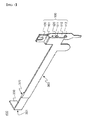
- FIG. 1 is a perspective view showing a bus bar according to the present invention.
- a bus bar 400 includes a power input part 100, a power output part 200, a plate-shaped main body 300, and a fastening part 120.
- the bus bar 400 further includes a terminal connection member 110 and a step 320.
- the power input part 100 is bent (see reference numeral 101) toward the terminal connection member 110 and is fastened (see reference numeral 130) to the terminal connection member 110 by rolling.
- Such a fastening method does not require additional connection members for fastening. Since an additional space necessary to mount the connection members and an additional process of mounting the connection members are not necessary, it is possible to efficiently assemble a compact battery module.
- the terminal connection member 110 includes two fastening holes 111 and 112, by which the terminal connection member 110 is fastened to a battery pack case (not shown) or an external member (not shown) by coupling.
- the power output part 200 is bent (see reference numeral 201) toward an input terminal part (not shown) of a battery pack (not shown).
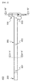
- FIG. 2 is a side view showing a bus bar according to an embodiment of the present invention
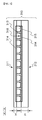
- FIGS. 3 and 4 are sectional views of FIG. 2 .
- the plate-shaped main body 300 is configured to have a structure in which opposite ends of the plate-shaped main body 300 are continuously connected with the power input part 100 and the power output part 200.
- the plate-shaped main body 300 includes a step 320, by which the plate-shaped main body 300 is fastened to the battery pack case (not shown) or the external member (not shown) by coupling.
- a groove (not shown) corresponding to the step 320 is formed at the battery pack case (not shown) or the external member (not shown).
- Such a method of fastening the step 320 to the groove corresponding thereto does not require additional connection members for fastening, and therefore, it is also possible to efficiently assemble a compact battery module.
- the construction of the power input part 100 is achieved through the coupling between the power input part 100 and the terminal connection member 110.
- the power input part 100 is formed in a bracket shape such that the power input part 100 is fastened to the battery pack case (not shown) or the external member (not shown) by coupling.
- the bus bar 400 includes the power input part 100, the plate-shaped main body 300, and the power output part 200, each of which is configured to have a structure including a vapor chamber 310.
- the vapor chamber 310 includes an upper plate 311 and a lower plate 312, both of which are made of copper.
- a thickness H' of the upper plate 311 is less than a thickness H of the lower plate 312.
- support members 313 and mesh structures 314 are disposed in the vapor chamber 310, and micro flow channels 315, along which a coolant flows, are disposed between the upper plate 311 and the lower plate 312.
- the vapor chamber 310 including the micro flow channels 315 defined therein may be easily modified based on the shape of a cooling system. As shown in FIG. 4 , the vapor chamber 310 is also applied to the power input part 100 fastened by rolling (see reference numeral 130) and including the two fastening holes 111 and 112.
- the vapor chamber 319 structure is applied to the power input part 100, the plate-shaped main body 300, and the power output part 200, thereby achieving high heat conductivity based on flow of the coolant 316 in the vapor chamber 310.
- the coolant 316 flowing in the vapor chamber 310 may be water
- the vapor chamber 310 may be a heat exchange system in which the coolant is automatically circulated in the vapor chamber 310 by capillary force naturally generated when the phase of the coolant is changed in the micro flow channels 315.
- the phase of the coolant is changed in order of evaporation (vaporization) - vapor movement - liquefaction (condensation) - return.
- FIG. 5 is a graph showing time based local temperature change of the bus bar according to the present invention and a conventional bus bar.
- #1, #2, and #3 indicate positions 601, 602, and 603 of temperature measurement devices located on the surface of the bus bar 400.
- #1 indicates a position 601 of the bus bar 400 at the power output part 200 side
- #2 indicates a position 602 of the middle portion of the plate-shaped main body 30
- #3 indicates a position 603 of the bus bar 400 at the power input part 100 side.
- the graph of FIG. 5 shows time (X axis) based temperature (Y axis) change of the conventional bus bar (not shown) at regions 501, 502, and 503 and the bus bar 400 according to the present invention at regions 511, 512, and 513 while current is supplied to the bus bar 400.
- the conventional bus bar (not shown) has a temperature deviation of 50 to 60 degrees after the lapse of 1000 seconds, and hot spots are generated at positions #1 and #2.
- the bus bar 400 according to the present invention has a temperature deviation of 10 to 15 degrees, and the overall temperature of the bus bar 400 is uniform.
- the conventional bus bar made of copper has a heat transfer coefficient of about 400 W/mK
- the bus bar 400 according to the present invention has a heat transfer coefficient of about 5,000 W/mK.
- the vapor chamber 319 structure is applied to the power input part 100, the plate-shaped main body 300, and the power output part 200, thereby achieving overall uniform temperature of the bus bar 400 and thus reducing temperature deviation and effectively discharging heat generated from the bus bar 400 outside.
Landscapes
- Chemical & Material Sciences (AREA)
- Chemical Kinetics & Catalysis (AREA)
- Electrochemistry (AREA)
- General Chemical & Material Sciences (AREA)
- Engineering & Computer Science (AREA)
- Manufacturing & Machinery (AREA)
- General Engineering & Computer Science (AREA)
- Life Sciences & Earth Sciences (AREA)
- Sustainable Development (AREA)
- Physics & Mathematics (AREA)
- Thermal Sciences (AREA)
- Mechanical Engineering (AREA)
- Inorganic Chemistry (AREA)
- Connection Of Batteries Or Terminals (AREA)
- Secondary Cells (AREA)
- Battery Mounting, Suspending (AREA)
- Cooling, Air Intake And Gas Exhaust, And Fuel Tank Arrangements In Propulsion Units (AREA)
- Arrangement Or Mounting Of Propulsion Units For Vehicles (AREA)
Applications Claiming Priority (2)
| Application Number | Priority Date | Filing Date | Title |
|---|---|---|---|
| KR1020120012024A KR101431717B1 (ko) | 2012-02-06 | 2012-02-06 | 신규한 구조의 버스 바 |
| PCT/KR2013/000518 WO2013118985A1 (fr) | 2012-02-06 | 2013-01-23 | Barre de bus dotée d'une structure innovante |
Publications (3)
| Publication Number | Publication Date |
|---|---|
| EP2814089A1 true EP2814089A1 (fr) | 2014-12-17 |
| EP2814089A4 EP2814089A4 (fr) | 2015-08-05 |
| EP2814089B1 EP2814089B1 (fr) | 2017-12-20 |
Family
ID=48947717
Family Applications (1)
| Application Number | Title | Priority Date | Filing Date |
|---|---|---|---|
| EP13746319.6A Active EP2814089B1 (fr) | 2012-02-06 | 2013-01-23 | Bloc-batterie avec barre de bus dotée d'une structure innovante |
Country Status (7)
| Country | Link |
|---|---|
| US (1) | US10784015B2 (fr) |
| EP (1) | EP2814089B1 (fr) |
| JP (1) | JP6049752B2 (fr) |
| KR (1) | KR101431717B1 (fr) |
| CN (1) | CN103959513B (fr) |
| TW (1) | TWI481096B (fr) |
| WO (1) | WO2013118985A1 (fr) |
Cited By (3)
| Publication number | Priority date | Publication date | Assignee | Title |
|---|---|---|---|---|
| DE102015219609A1 (de) * | 2015-10-09 | 2017-04-13 | Volkswagen Aktiengesellschaft | Stromverteilerschiene mit einem Wärmeleitrohr |
| DE102015222713A1 (de) * | 2015-11-18 | 2017-05-18 | Bayerische Motoren Werke Aktiengesellschaft | Elektrizitätsstrang für ein Kraftfahrzeug |
| DE102016206510A1 (de) * | 2016-04-18 | 2017-10-19 | Volkswagen Aktiengesellschaft | Batterieeinheit |
Families Citing this family (27)
| Publication number | Priority date | Publication date | Assignee | Title |
|---|---|---|---|---|
| DE102014223353A1 (de) * | 2014-11-17 | 2016-05-19 | Robert Bosch Gmbh | Vorrichtung zum Befestigen und Kontaktieren eines elektrischen Bauelements und Verfahren zum Herstellen der Vorrichtung |
| KR102022590B1 (ko) * | 2015-09-21 | 2019-09-18 | 주식회사 엘지화학 | 배터리 모듈 |
| KR102018719B1 (ko) * | 2016-02-12 | 2019-09-04 | 주식회사 엘지화학 | 배터리 셀 냉각용 버스바 및 이를 이용한 배터리 모듈 |
| US11177518B2 (en) * | 2016-03-29 | 2021-11-16 | Amogreentech Co., Ltd. | Heat-radiating cartridge, and battery pack for electric vehicle using same |
| KR101990107B1 (ko) * | 2016-03-29 | 2019-06-19 | 주식회사 아모그린텍 | 방열 모듈 및 이용한 전기자동차용 전지팩 |
| US10516191B2 (en) * | 2016-09-07 | 2019-12-24 | Thunder Power New Energy Vehicle Development Company Limited | Methods and systems for busbar cooling |
| US10403943B2 (en) * | 2016-09-07 | 2019-09-03 | Thunder Power New Energy Vehicle Development Company Limited | Battery system |
| CN106602177B (zh) * | 2016-12-16 | 2020-03-17 | 浙江南都电源动力股份有限公司 | 一种适用软包动力电池的模组顶部加热系统及控制方法 |
| KR102087699B1 (ko) * | 2017-11-27 | 2020-04-28 | 주식회사 유라코퍼레이션 | 연성회로기판 및 이를 이용하는 배터리팩 |
| US11189887B2 (en) * | 2017-03-16 | 2021-11-30 | Ford Global Technologies, Llc | Busbar assembly for an electrified vehicle and method of forming the same |
| US10003112B1 (en) * | 2017-12-01 | 2018-06-19 | GM Global Technology Operations LLC | Battery backplane assembly with integrated bus bar connections and thermal management features |
| US11894532B2 (en) * | 2018-08-21 | 2024-02-06 | Sk On Co., Ltd. | Battery module and manufacturing method thereof |
| JP7115208B2 (ja) * | 2018-10-12 | 2022-08-09 | 住友電装株式会社 | 電気接続箱 |
| DE102018222404B4 (de) * | 2018-12-20 | 2020-08-13 | Volkswagen Aktiengesellschaft | Anordnung zur elektrischen Verbindung elektrochemischer Speicherzellen und/oder Zellmodule untereinander sowie Batterie oder Fahrzeug dazu |
| DE102019200817A1 (de) * | 2019-01-23 | 2020-07-23 | Audi Ag | Kühleinrichtung zur Kühlung von Batteriezellen, Batterie und Kraftfahrzeug |
| JP7016836B2 (ja) * | 2019-06-10 | 2022-02-07 | 矢崎総業株式会社 | 導電システム |
| CN112582754B (zh) * | 2019-09-27 | 2022-05-13 | 比亚迪股份有限公司 | 一种动力排防护装置、动力电池包及车辆 |
| CN113644384A (zh) | 2020-04-27 | 2021-11-12 | 比亚迪股份有限公司 | 铜排保护结构、电池包及电动汽车 |
| DE102021101528A1 (de) * | 2021-01-25 | 2022-07-28 | Phoenix Contact E-Mobility Gmbh | Hochstrommodul für Ladesteckverbinderteil |
| CN113036263A (zh) * | 2021-03-08 | 2021-06-25 | 山东大学 | 一种基于液体相变材料的电池包热管理装置及电动汽车 |
| KR20230076450A (ko) * | 2021-11-24 | 2023-05-31 | 주식회사 엘지에너지솔루션 | 전지 모듈 및 이를 포함하는 전지 팩 |
| US20230275299A1 (en) | 2022-02-25 | 2023-08-31 | Inventus Power, Inc. | Battery pack with thermal protection |
| DE102022105188A1 (de) | 2022-03-04 | 2023-09-07 | iinovis GmbH | Vorrichtung zum elektrischen Verbinden einer Ladedose mit einer elektrischen Speichereinrichtung |
| DE102022108336A1 (de) | 2022-04-06 | 2023-10-12 | Lisa Dräxlmaier GmbH | Stromschiene mit passiver kühlung |
| DE102022108334A1 (de) | 2022-04-06 | 2023-10-12 | Lisa Dräxlmaier GmbH | Stromschiene mit aufnahme für eine kühlung |
| DE102022114560A1 (de) | 2022-06-09 | 2023-12-14 | Bayerische Motoren Werke Aktiengesellschaft | Stromschiene mit pulsierendem Wärmerohr, Baugruppe sowie Hochvoltbordnetz |
| DE102022132102A1 (de) | 2022-12-02 | 2024-06-13 | Audi Aktiengesellschaft | Hochvoltbordnetz und Verfahren zum Kühlen einer Hochvoltleitung |
Family Cites Families (21)
| Publication number | Priority date | Publication date | Assignee | Title |
|---|---|---|---|---|
| US3728585A (en) * | 1972-06-12 | 1973-04-17 | Gen Electric | Electric switchboard assembly with bus bar heat pipe means |
| JPS58166027U (ja) * | 1982-04-30 | 1983-11-05 | 株式会社東芝 | コンデンサ |
| JPH0743867Y2 (ja) * | 1989-07-05 | 1995-10-09 | 動力炉・核燃料開発事業団 | 給電用ブスバー |
| GB9005243D0 (en) * | 1990-03-08 | 1990-05-02 | Bicc Plc | An improved isolated phase busbar installation |
| US6010800A (en) * | 1998-06-17 | 2000-01-04 | Hughes Electronics Corporation | Method and apparatus for transferring heat generated by a battery |
| JP4164212B2 (ja) * | 1999-11-18 | 2008-10-15 | 株式会社日立製作所 | 電池モジュール及び電力供給装置 |
| JP4204237B2 (ja) * | 2001-03-21 | 2009-01-07 | 日本碍子株式会社 | リチウム二次単電池およびリチウム二次単電池の接続構造体 |
| JP2006210245A (ja) | 2005-01-31 | 2006-08-10 | Toyota Motor Corp | 電池モジュールの冷却装置 |
| KR100936262B1 (ko) * | 2005-10-21 | 2010-01-12 | 주식회사 엘지화학 | 신규한 구조의 전기 접속용 버스 바 및 그것을 포함하고있는 전지모듈 |
| DE102006058327B3 (de) * | 2006-12-11 | 2008-05-15 | Siemens Ag | Stromschienenpaket |
| KR100887759B1 (ko) * | 2007-11-12 | 2009-03-12 | 미래특수금속 주식회사 | 동복알루미늄 부스 바 제조방법 |
| JP2009245730A (ja) | 2008-03-31 | 2009-10-22 | West Japan Railway Co | 電池接続具 |
| US20100030733A1 (en) * | 2008-08-01 | 2010-02-04 | Draughn Jr Alphonza | Transforming SQL Queries with Table Subqueries |
| US7786384B2 (en) * | 2008-08-29 | 2010-08-31 | Mauricio Diaz | Efficient high-ampacity bowl-shaped tubular conductors |
| US20100146169A1 (en) * | 2008-12-05 | 2010-06-10 | Nuvoton Technology Corporation | Bus-handling |
| DE102009005124A1 (de) * | 2009-01-19 | 2010-07-29 | Li-Tec Battery Gmbh | Elektrochemische Energiespeichervorrichtung |
| JP5514578B2 (ja) * | 2009-02-24 | 2014-06-04 | 矢崎総業株式会社 | 組電池冷却構造 |
| KR20100096755A (ko) | 2009-02-25 | 2010-09-02 | 에스비리모티브 주식회사 | 전지모듈 |
| US7952875B2 (en) | 2009-05-29 | 2011-05-31 | GM Global Technology Operations LLC | Stacked busbar assembly with integrated cooling |
| JP2011029103A (ja) * | 2009-07-29 | 2011-02-10 | Kawasaki Shipbuilding Corp | 電池冷却装置 |
| KR101097226B1 (ko) * | 2010-02-01 | 2011-12-21 | 에스비리모티브 주식회사 | 배터리 팩 |
-
2012
- 2012-02-06 KR KR1020120012024A patent/KR101431717B1/ko active IP Right Grant
-
2013
- 2013-01-23 EP EP13746319.6A patent/EP2814089B1/fr active Active
- 2013-01-23 CN CN201380004119.XA patent/CN103959513B/zh active Active
- 2013-01-23 WO PCT/KR2013/000518 patent/WO2013118985A1/fr active Application Filing
- 2013-01-23 JP JP2014547124A patent/JP6049752B2/ja active Active
- 2013-01-23 US US14/360,869 patent/US10784015B2/en active Active
- 2013-01-25 TW TW102102810A patent/TWI481096B/zh active
Cited By (4)
| Publication number | Priority date | Publication date | Assignee | Title |
|---|---|---|---|---|
| DE102015219609A1 (de) * | 2015-10-09 | 2017-04-13 | Volkswagen Aktiengesellschaft | Stromverteilerschiene mit einem Wärmeleitrohr |
| DE102015222713A1 (de) * | 2015-11-18 | 2017-05-18 | Bayerische Motoren Werke Aktiengesellschaft | Elektrizitätsstrang für ein Kraftfahrzeug |
| DE102016206510A1 (de) * | 2016-04-18 | 2017-10-19 | Volkswagen Aktiengesellschaft | Batterieeinheit |
| DE102016206510B4 (de) | 2016-04-18 | 2023-10-12 | Volkswagen Aktiengesellschaft | Batterieeinheit |
Also Published As
| Publication number | Publication date |
|---|---|
| US10784015B2 (en) | 2020-09-22 |
| EP2814089A4 (fr) | 2015-08-05 |
| CN103959513B (zh) | 2016-09-14 |
| WO2013118985A1 (fr) | 2013-08-15 |
| EP2814089B1 (fr) | 2017-12-20 |
| KR20130090700A (ko) | 2013-08-14 |
| TW201338244A (zh) | 2013-09-16 |
| KR101431717B1 (ko) | 2014-08-26 |
| TWI481096B (zh) | 2015-04-11 |
| CN103959513A (zh) | 2014-07-30 |
| JP6049752B2 (ja) | 2016-12-21 |
| US20140370339A1 (en) | 2014-12-18 |
| JP2015507818A (ja) | 2015-03-12 |
Similar Documents
| Publication | Publication Date | Title |
|---|---|---|
| US10784015B2 (en) | Bus bar with novel structure | |
| US8790809B2 (en) | Battery having a housing partially filled with cooling fluid | |
| CN105452025B (zh) | 用于电池的温度控制器 | |
| US20180294452A1 (en) | Tray, power battery pack and electric vehicle | |
| JP5137480B2 (ja) | 車両用の電源装置 | |
| KR101108191B1 (ko) | 배터리 팩 | |
| JP6693480B2 (ja) | 端子冷却装置 | |
| JP7155168B2 (ja) | 電源装置及び電源装置を備える電動車両 | |
| KR20120004322A (ko) | 전지 모듈 | |
| JP2009009853A (ja) | 車両用の電源装置 | |
| JP2013157111A (ja) | 組電池の冷却兼加熱構造 | |
| JP2009134936A (ja) | バッテリシステム | |
| CN109659643B (zh) | 电池组电池模块、二次电池组以及机动车 | |
| US20150207190A1 (en) | Temperature Adjusting Apparatus and Battery Having the Same | |
| CN113544897A (zh) | 用于冷却电池模块的冷却系统、高压电池和机动车 | |
| EP3392955B1 (fr) | Systeme de refrigeration contenant des caloducs. | |
| CN112952237A (zh) | 电池热管理装置、电池模组及电池热管理方法 | |
| CN111355005A (zh) | 用于电连接的组件及电池组或车辆 | |
| CN116744546B (zh) | 超导散热电池保护板 | |
| KR102683482B1 (ko) | 전지 팩 | |
| JP2015002105A (ja) | 電池モジュールの冷却装置 | |
| CN212461818U (zh) | 基于热管的纯电动汽车蓄电池冷却系统 | |
| KR102328975B1 (ko) | 배터리 모듈 | |
| CN221304788U (zh) | 二次电池 | |
| CN216928704U (zh) | 一种用于安装电池模组的散热组件及电池包 |
Legal Events
| Date | Code | Title | Description |
|---|---|---|---|
| PUAI | Public reference made under article 153(3) epc to a published international application that has entered the european phase |
Free format text: ORIGINAL CODE: 0009012 |
|
| 17P | Request for examination filed |
Effective date: 20140526 |
|
| AK | Designated contracting states |
Kind code of ref document: A1 Designated state(s): AL AT BE BG CH CY CZ DE DK EE ES FI FR GB GR HR HU IE IS IT LI LT LU LV MC MK MT NL NO PL PT RO RS SE SI SK SM TR |
|
| AX | Request for extension of the european patent |
Extension state: BA ME |
|
| RIN1 | Information on inventor provided before grant (corrected) |
Inventor name: PARK, WON CHAN Inventor name: KIM, KYOUNG HO Inventor name: IM, YE HOON Inventor name: CHUNG, CHAE HO |
|
| DAX | Request for extension of the european patent (deleted) | ||
| RA4 | Supplementary search report drawn up and despatched (corrected) |
Effective date: 20150706 |
|
| RIC1 | Information provided on ipc code assigned before grant |
Ipc: H01M 2/30 20060101AFI20150630BHEP Ipc: H01M 2/20 20060101ALI20150630BHEP Ipc: H02G 5/10 20060101ALI20150630BHEP Ipc: H01B 5/02 20060101ALI20150630BHEP Ipc: H01M 2/40 20060101ALI20150630BHEP |
|
| 17Q | First examination report despatched |
Effective date: 20160309 |
|
| REG | Reference to a national code |
Ref country code: DE Ref legal event code: R079 Ref document number: 602013031062 Country of ref document: DE Free format text: PREVIOUS MAIN CLASS: H01M0002300000 Ipc: F28D0015020000 |
|
| GRAP | Despatch of communication of intention to grant a patent |
Free format text: ORIGINAL CODE: EPIDOSNIGR1 |
|
| RIC1 | Information provided on ipc code assigned before grant |
Ipc: H01B 5/02 20060101ALI20170824BHEP Ipc: H02G 5/10 20060101ALI20170824BHEP Ipc: H01M 10/6567 20140101ALI20170824BHEP Ipc: F28D 15/02 20060101AFI20170824BHEP Ipc: H01M 2/20 20060101ALI20170824BHEP Ipc: H01M 10/625 20140101ALI20170824BHEP Ipc: H01M 2/30 20060101ALI20170824BHEP Ipc: F28D 15/04 20060101ALI20170824BHEP Ipc: H01M 10/613 20140101ALI20170824BHEP Ipc: H01M 10/6569 20140101ALI20170824BHEP Ipc: H01M 10/6552 20140101ALI20170824BHEP Ipc: H01M 2/40 20060101ALI20170824BHEP Ipc: H01M 10/6553 20140101ALI20170824BHEP |
|
| RIC1 | Information provided on ipc code assigned before grant |
Ipc: H01M 10/6567 20140101ALI20170828BHEP Ipc: F28D 15/02 20060101AFI20170828BHEP Ipc: H01M 10/6552 20140101ALI20170828BHEP Ipc: F28D 15/04 20060101ALI20170828BHEP Ipc: H01M 10/613 20140101ALI20170828BHEP Ipc: H01B 5/02 20060101ALI20170828BHEP Ipc: H01M 10/625 20140101ALI20170828BHEP Ipc: H01M 10/6553 20140101ALI20170828BHEP Ipc: H01M 10/6569 20140101ALI20170828BHEP Ipc: H01M 2/20 20060101ALI20170828BHEP |
|
| INTG | Intention to grant announced |
Effective date: 20170922 |
|
| GRAS | Grant fee paid |
Free format text: ORIGINAL CODE: EPIDOSNIGR3 |
|
| GRAA | (expected) grant |
Free format text: ORIGINAL CODE: 0009210 |
|
| RIN1 | Information on inventor provided before grant (corrected) |
Inventor name: KIM, KYOUNG HO Inventor name: IM, YE HOON Inventor name: CHUNG, CHAE HO Inventor name: PARK, WON CHAN |
|
| AK | Designated contracting states |
Kind code of ref document: B1 Designated state(s): AL AT BE BG CH CY CZ DE DK EE ES FI FR GB GR HR HU IE IS IT LI LT LU LV MC MK MT NL NO PL PT RO RS SE SI SK SM TR |
|
| REG | Reference to a national code |
Ref country code: GB Ref legal event code: FG4D |
|
| REG | Reference to a national code |
Ref country code: CH Ref legal event code: EP |
|
| REG | Reference to a national code |
Ref country code: IE Ref legal event code: FG4D |
|
| REG | Reference to a national code |
Ref country code: AT Ref legal event code: REF Ref document number: 956756 Country of ref document: AT Kind code of ref document: T Effective date: 20180115 |
|
| REG | Reference to a national code |
Ref country code: DE Ref legal event code: R096 Ref document number: 602013031062 Country of ref document: DE |
|
| REG | Reference to a national code |
Ref country code: NL Ref legal event code: MP Effective date: 20171220 |
|
| PG25 | Lapsed in a contracting state [announced via postgrant information from national office to epo] |
Ref country code: NO Free format text: LAPSE BECAUSE OF FAILURE TO SUBMIT A TRANSLATION OF THE DESCRIPTION OR TO PAY THE FEE WITHIN THE PRESCRIBED TIME-LIMIT Effective date: 20180320 Ref country code: FI Free format text: LAPSE BECAUSE OF FAILURE TO SUBMIT A TRANSLATION OF THE DESCRIPTION OR TO PAY THE FEE WITHIN THE PRESCRIBED TIME-LIMIT Effective date: 20171220 Ref country code: LT Free format text: LAPSE BECAUSE OF FAILURE TO SUBMIT A TRANSLATION OF THE DESCRIPTION OR TO PAY THE FEE WITHIN THE PRESCRIBED TIME-LIMIT Effective date: 20171220 Ref country code: SE Free format text: LAPSE BECAUSE OF FAILURE TO SUBMIT A TRANSLATION OF THE DESCRIPTION OR TO PAY THE FEE WITHIN THE PRESCRIBED TIME-LIMIT Effective date: 20171220 |
|
| REG | Reference to a national code |
Ref country code: LT Ref legal event code: MG4D |
|
| REG | Reference to a national code |
Ref country code: AT Ref legal event code: MK05 Ref document number: 956756 Country of ref document: AT Kind code of ref document: T Effective date: 20171220 |
|
| PG25 | Lapsed in a contracting state [announced via postgrant information from national office to epo] |
Ref country code: LV Free format text: LAPSE BECAUSE OF FAILURE TO SUBMIT A TRANSLATION OF THE DESCRIPTION OR TO PAY THE FEE WITHIN THE PRESCRIBED TIME-LIMIT Effective date: 20171220 Ref country code: GR Free format text: LAPSE BECAUSE OF FAILURE TO SUBMIT A TRANSLATION OF THE DESCRIPTION OR TO PAY THE FEE WITHIN THE PRESCRIBED TIME-LIMIT Effective date: 20180321 Ref country code: RS Free format text: LAPSE BECAUSE OF FAILURE TO SUBMIT A TRANSLATION OF THE DESCRIPTION OR TO PAY THE FEE WITHIN THE PRESCRIBED TIME-LIMIT Effective date: 20171220 Ref country code: HR Free format text: LAPSE BECAUSE OF FAILURE TO SUBMIT A TRANSLATION OF THE DESCRIPTION OR TO PAY THE FEE WITHIN THE PRESCRIBED TIME-LIMIT Effective date: 20171220 Ref country code: BG Free format text: LAPSE BECAUSE OF FAILURE TO SUBMIT A TRANSLATION OF THE DESCRIPTION OR TO PAY THE FEE WITHIN THE PRESCRIBED TIME-LIMIT Effective date: 20180320 |
|
| PG25 | Lapsed in a contracting state [announced via postgrant information from national office to epo] |
Ref country code: NL Free format text: LAPSE BECAUSE OF FAILURE TO SUBMIT A TRANSLATION OF THE DESCRIPTION OR TO PAY THE FEE WITHIN THE PRESCRIBED TIME-LIMIT Effective date: 20171220 |
|
| PG25 | Lapsed in a contracting state [announced via postgrant information from national office to epo] |
Ref country code: CZ Free format text: LAPSE BECAUSE OF FAILURE TO SUBMIT A TRANSLATION OF THE DESCRIPTION OR TO PAY THE FEE WITHIN THE PRESCRIBED TIME-LIMIT Effective date: 20171220 Ref country code: ES Free format text: LAPSE BECAUSE OF FAILURE TO SUBMIT A TRANSLATION OF THE DESCRIPTION OR TO PAY THE FEE WITHIN THE PRESCRIBED TIME-LIMIT Effective date: 20171220 Ref country code: CY Free format text: LAPSE BECAUSE OF FAILURE TO SUBMIT A TRANSLATION OF THE DESCRIPTION OR TO PAY THE FEE WITHIN THE PRESCRIBED TIME-LIMIT Effective date: 20171220 Ref country code: EE Free format text: LAPSE BECAUSE OF FAILURE TO SUBMIT A TRANSLATION OF THE DESCRIPTION OR TO PAY THE FEE WITHIN THE PRESCRIBED TIME-LIMIT Effective date: 20171220 Ref country code: SK Free format text: LAPSE BECAUSE OF FAILURE TO SUBMIT A TRANSLATION OF THE DESCRIPTION OR TO PAY THE FEE WITHIN THE PRESCRIBED TIME-LIMIT Effective date: 20171220 |
|
| PG25 | Lapsed in a contracting state [announced via postgrant information from national office to epo] |
Ref country code: IT Free format text: LAPSE BECAUSE OF FAILURE TO SUBMIT A TRANSLATION OF THE DESCRIPTION OR TO PAY THE FEE WITHIN THE PRESCRIBED TIME-LIMIT Effective date: 20171220 Ref country code: RO Free format text: LAPSE BECAUSE OF FAILURE TO SUBMIT A TRANSLATION OF THE DESCRIPTION OR TO PAY THE FEE WITHIN THE PRESCRIBED TIME-LIMIT Effective date: 20171220 Ref country code: SM Free format text: LAPSE BECAUSE OF FAILURE TO SUBMIT A TRANSLATION OF THE DESCRIPTION OR TO PAY THE FEE WITHIN THE PRESCRIBED TIME-LIMIT Effective date: 20171220 Ref country code: IS Free format text: LAPSE BECAUSE OF FAILURE TO SUBMIT A TRANSLATION OF THE DESCRIPTION OR TO PAY THE FEE WITHIN THE PRESCRIBED TIME-LIMIT Effective date: 20180420 Ref country code: AT Free format text: LAPSE BECAUSE OF FAILURE TO SUBMIT A TRANSLATION OF THE DESCRIPTION OR TO PAY THE FEE WITHIN THE PRESCRIBED TIME-LIMIT Effective date: 20171220 Ref country code: PL Free format text: LAPSE BECAUSE OF FAILURE TO SUBMIT A TRANSLATION OF THE DESCRIPTION OR TO PAY THE FEE WITHIN THE PRESCRIBED TIME-LIMIT Effective date: 20171220 |
|
| REG | Reference to a national code |
Ref country code: CH Ref legal event code: PL |
|
| RAP2 | Party data changed (patent owner data changed or rights of a patent transferred) |
Owner name: LG CHEM, LTD. |
|
| REG | Reference to a national code |
Ref country code: DE Ref legal event code: R097 Ref document number: 602013031062 Country of ref document: DE |
|
| PG25 | Lapsed in a contracting state [announced via postgrant information from national office to epo] |
Ref country code: MC Free format text: LAPSE BECAUSE OF FAILURE TO SUBMIT A TRANSLATION OF THE DESCRIPTION OR TO PAY THE FEE WITHIN THE PRESCRIBED TIME-LIMIT Effective date: 20171220 |
|
| PLBE | No opposition filed within time limit |
Free format text: ORIGINAL CODE: 0009261 |
|
| STAA | Information on the status of an ep patent application or granted ep patent |
Free format text: STATUS: NO OPPOSITION FILED WITHIN TIME LIMIT |
|
| PG25 | Lapsed in a contracting state [announced via postgrant information from national office to epo] |
Ref country code: FR Free format text: LAPSE BECAUSE OF NON-PAYMENT OF DUE FEES Effective date: 20180220 Ref country code: LU Free format text: LAPSE BECAUSE OF NON-PAYMENT OF DUE FEES Effective date: 20180123 |
|
| REG | Reference to a national code |
Ref country code: IE Ref legal event code: MM4A |
|
| REG | Reference to a national code |
Ref country code: FR Ref legal event code: ST Effective date: 20180928 |
|
| REG | Reference to a national code |
Ref country code: BE Ref legal event code: MM Effective date: 20180131 |
|
| GBPC | Gb: european patent ceased through non-payment of renewal fee |
Effective date: 20180320 |
|
| 26N | No opposition filed |
Effective date: 20180921 |
|
| PG25 | Lapsed in a contracting state [announced via postgrant information from national office to epo] |
Ref country code: LI Free format text: LAPSE BECAUSE OF NON-PAYMENT OF DUE FEES Effective date: 20180131 Ref country code: BE Free format text: LAPSE BECAUSE OF NON-PAYMENT OF DUE FEES Effective date: 20180131 Ref country code: DK Free format text: LAPSE BECAUSE OF FAILURE TO SUBMIT A TRANSLATION OF THE DESCRIPTION OR TO PAY THE FEE WITHIN THE PRESCRIBED TIME-LIMIT Effective date: 20171220 Ref country code: CH Free format text: LAPSE BECAUSE OF NON-PAYMENT OF DUE FEES Effective date: 20180131 |
|
| PG25 | Lapsed in a contracting state [announced via postgrant information from national office to epo] |
Ref country code: IE Free format text: LAPSE BECAUSE OF NON-PAYMENT OF DUE FEES Effective date: 20180123 |
|
| PG25 | Lapsed in a contracting state [announced via postgrant information from national office to epo] |
Ref country code: GB Free format text: LAPSE BECAUSE OF NON-PAYMENT OF DUE FEES Effective date: 20180320 Ref country code: SI Free format text: LAPSE BECAUSE OF FAILURE TO SUBMIT A TRANSLATION OF THE DESCRIPTION OR TO PAY THE FEE WITHIN THE PRESCRIBED TIME-LIMIT Effective date: 20171220 |
|
| PG25 | Lapsed in a contracting state [announced via postgrant information from national office to epo] |
Ref country code: MT Free format text: LAPSE BECAUSE OF NON-PAYMENT OF DUE FEES Effective date: 20180123 |
|
| PG25 | Lapsed in a contracting state [announced via postgrant information from national office to epo] |
Ref country code: TR Free format text: LAPSE BECAUSE OF FAILURE TO SUBMIT A TRANSLATION OF THE DESCRIPTION OR TO PAY THE FEE WITHIN THE PRESCRIBED TIME-LIMIT Effective date: 20171220 |
|
| PG25 | Lapsed in a contracting state [announced via postgrant information from national office to epo] |
Ref country code: PT Free format text: LAPSE BECAUSE OF FAILURE TO SUBMIT A TRANSLATION OF THE DESCRIPTION OR TO PAY THE FEE WITHIN THE PRESCRIBED TIME-LIMIT Effective date: 20171220 Ref country code: HU Free format text: LAPSE BECAUSE OF FAILURE TO SUBMIT A TRANSLATION OF THE DESCRIPTION OR TO PAY THE FEE WITHIN THE PRESCRIBED TIME-LIMIT; INVALID AB INITIO Effective date: 20130123 |
|
| PG25 | Lapsed in a contracting state [announced via postgrant information from national office to epo] |
Ref country code: MK Free format text: LAPSE BECAUSE OF NON-PAYMENT OF DUE FEES Effective date: 20171220 |
|
| PG25 | Lapsed in a contracting state [announced via postgrant information from national office to epo] |
Ref country code: AL Free format text: LAPSE BECAUSE OF FAILURE TO SUBMIT A TRANSLATION OF THE DESCRIPTION OR TO PAY THE FEE WITHIN THE PRESCRIBED TIME-LIMIT Effective date: 20171220 |
|
| P01 | Opt-out of the competence of the unified patent court (upc) registered |
Effective date: 20230323 |
|
| REG | Reference to a national code |
Ref country code: DE Ref legal event code: R081 Ref document number: 602013031062 Country of ref document: DE Owner name: LG ENERGY SOLUTION, LTD., KR Free format text: FORMER OWNER: LG CHEM. LTD., SEOUL, KR |
|
| PGFP | Annual fee paid to national office [announced via postgrant information from national office to epo] |
Ref country code: DE Payment date: 20231220 Year of fee payment: 12 |