EP2811139B1 - Engine control device for work vehicle - Google Patents
Engine control device for work vehicle Download PDFInfo
- Publication number
- EP2811139B1 EP2811139B1 EP13743737.2A EP13743737A EP2811139B1 EP 2811139 B1 EP2811139 B1 EP 2811139B1 EP 13743737 A EP13743737 A EP 13743737A EP 2811139 B1 EP2811139 B1 EP 2811139B1
- Authority
- EP
- European Patent Office
- Prior art keywords
- rotation speed
- engine
- target rotation
- speed
- torque converter
- Prior art date
- Legal status (The legal status is an assumption and is not a legal conclusion. Google has not performed a legal analysis and makes no representation as to the accuracy of the status listed.)
- Active
Links
- 230000007423 decrease Effects 0.000 claims description 25
- 238000001514 detection method Methods 0.000 claims description 8
- 230000002441 reversible effect Effects 0.000 description 22
- 230000005540 biological transmission Effects 0.000 description 16
- 238000009412 basement excavation Methods 0.000 description 14
- 238000010586 diagram Methods 0.000 description 14
- 239000002689 soil Substances 0.000 description 10
- 238000000034 method Methods 0.000 description 8
- 238000010521 absorption reaction Methods 0.000 description 6
- 230000008569 process Effects 0.000 description 6
- 230000008901 benefit Effects 0.000 description 5
- 238000006073 displacement reaction Methods 0.000 description 4
- 239000000446 fuel Substances 0.000 description 4
- 238000011068 loading method Methods 0.000 description 4
- 230000000630 rising effect Effects 0.000 description 4
- 230000008859 change Effects 0.000 description 3
- 230000003247 decreasing effect Effects 0.000 description 3
- 230000000994 depressogenic effect Effects 0.000 description 3
- 230000007935 neutral effect Effects 0.000 description 3
- 238000005096 rolling process Methods 0.000 description 3
- 230000009471 action Effects 0.000 description 2
- 230000000694 effects Effects 0.000 description 2
- 238000005516 engineering process Methods 0.000 description 2
- 230000035939 shock Effects 0.000 description 2
- 230000001133 acceleration Effects 0.000 description 1
- 230000004913 activation Effects 0.000 description 1
- 238000002485 combustion reaction Methods 0.000 description 1
- 230000001419 dependent effect Effects 0.000 description 1
- 238000011161 development Methods 0.000 description 1
- 230000018109 developmental process Effects 0.000 description 1
- 239000012530 fluid Substances 0.000 description 1
- 238000002347 injection Methods 0.000 description 1
- 239000007924 injection Substances 0.000 description 1
- 230000002093 peripheral effect Effects 0.000 description 1
- 230000002035 prolonged effect Effects 0.000 description 1
- 230000004044 response Effects 0.000 description 1
- 239000000243 solution Substances 0.000 description 1
- 230000001360 synchronised effect Effects 0.000 description 1
Images


Classifications
-
- F—MECHANICAL ENGINEERING; LIGHTING; HEATING; WEAPONS; BLASTING
- F02—COMBUSTION ENGINES; HOT-GAS OR COMBUSTION-PRODUCT ENGINE PLANTS
- F02D—CONTROLLING COMBUSTION ENGINES
- F02D31/00—Use of speed-sensing governors to control combustion engines, not otherwise provided for
- F02D31/001—Electric control of rotation speed
-
- B—PERFORMING OPERATIONS; TRANSPORTING
- B60—VEHICLES IN GENERAL
- B60K—ARRANGEMENT OR MOUNTING OF PROPULSION UNITS OR OF TRANSMISSIONS IN VEHICLES; ARRANGEMENT OR MOUNTING OF PLURAL DIVERSE PRIME-MOVERS IN VEHICLES; AUXILIARY DRIVES FOR VEHICLES; INSTRUMENTATION OR DASHBOARDS FOR VEHICLES; ARRANGEMENTS IN CONNECTION WITH COOLING, AIR INTAKE, GAS EXHAUST OR FUEL SUPPLY OF PROPULSION UNITS IN VEHICLES
- B60K31/00—Vehicle fittings, acting on a single sub-unit only, for automatically controlling vehicle speed, i.e. preventing speed from exceeding an arbitrarily established velocity or maintaining speed at a particular velocity, as selected by the vehicle operator
-
- F—MECHANICAL ENGINEERING; LIGHTING; HEATING; WEAPONS; BLASTING
- F02—COMBUSTION ENGINES; HOT-GAS OR COMBUSTION-PRODUCT ENGINE PLANTS
- F02D—CONTROLLING COMBUSTION ENGINES
- F02D31/00—Use of speed-sensing governors to control combustion engines, not otherwise provided for
- F02D31/001—Electric control of rotation speed
- F02D31/007—Electric control of rotation speed controlling fuel supply
-
- F—MECHANICAL ENGINEERING; LIGHTING; HEATING; WEAPONS; BLASTING
- F02—COMBUSTION ENGINES; HOT-GAS OR COMBUSTION-PRODUCT ENGINE PLANTS
- F02D—CONTROLLING COMBUSTION ENGINES
- F02D41/00—Electrical control of supply of combustible mixture or its constituents
- F02D41/02—Circuit arrangements for generating control signals
- F02D41/021—Introducing corrections for particular conditions exterior to the engine
- F02D41/0215—Introducing corrections for particular conditions exterior to the engine in relation with elements of the transmission
-
- F—MECHANICAL ENGINEERING; LIGHTING; HEATING; WEAPONS; BLASTING
- F02—COMBUSTION ENGINES; HOT-GAS OR COMBUSTION-PRODUCT ENGINE PLANTS
- F02D—CONTROLLING COMBUSTION ENGINES
- F02D41/00—Electrical control of supply of combustible mixture or its constituents
- F02D41/02—Circuit arrangements for generating control signals
- F02D41/04—Introducing corrections for particular operating conditions
- F02D41/08—Introducing corrections for particular operating conditions for idling
- F02D41/083—Introducing corrections for particular operating conditions for idling taking into account engine load variation, e.g. air-conditionning
-
- F—MECHANICAL ENGINEERING; LIGHTING; HEATING; WEAPONS; BLASTING
- F16—ENGINEERING ELEMENTS AND UNITS; GENERAL MEASURES FOR PRODUCING AND MAINTAINING EFFECTIVE FUNCTIONING OF MACHINES OR INSTALLATIONS; THERMAL INSULATION IN GENERAL
- F16H—GEARING
- F16H63/00—Control outputs from the control unit to change-speed- or reversing-gearings for conveying rotary motion or to other devices than the final output mechanism
- F16H63/40—Control outputs from the control unit to change-speed- or reversing-gearings for conveying rotary motion or to other devices than the final output mechanism comprising signals other than signals for actuating the final output mechanisms
- F16H63/50—Signals to an engine or motor
-
- B—PERFORMING OPERATIONS; TRANSPORTING
- B60—VEHICLES IN GENERAL
- B60W—CONJOINT CONTROL OF VEHICLE SUB-UNITS OF DIFFERENT TYPE OR DIFFERENT FUNCTION; CONTROL SYSTEMS SPECIALLY ADAPTED FOR HYBRID VEHICLES; ROAD VEHICLE DRIVE CONTROL SYSTEMS FOR PURPOSES NOT RELATED TO THE CONTROL OF A PARTICULAR SUB-UNIT
- B60W2510/00—Input parameters relating to a particular sub-units
- B60W2510/10—Change speed gearings
- B60W2510/1005—Transmission ratio engaged
-
- B—PERFORMING OPERATIONS; TRANSPORTING
- B60—VEHICLES IN GENERAL
- B60W—CONJOINT CONTROL OF VEHICLE SUB-UNITS OF DIFFERENT TYPE OR DIFFERENT FUNCTION; CONTROL SYSTEMS SPECIALLY ADAPTED FOR HYBRID VEHICLES; ROAD VEHICLE DRIVE CONTROL SYSTEMS FOR PURPOSES NOT RELATED TO THE CONTROL OF A PARTICULAR SUB-UNIT
- B60W2710/00—Output or target parameters relating to a particular sub-units
- B60W2710/06—Combustion engines, Gas turbines
- B60W2710/0644—Engine speed
-
- B—PERFORMING OPERATIONS; TRANSPORTING
- B60—VEHICLES IN GENERAL
- B60Y—INDEXING SCHEME RELATING TO ASPECTS CROSS-CUTTING VEHICLE TECHNOLOGY
- B60Y2400/00—Special features of vehicle units
- B60Y2400/42—Clutches or brakes
- B60Y2400/426—Hydrodynamic couplings, e.g. torque converters
-
- F—MECHANICAL ENGINEERING; LIGHTING; HEATING; WEAPONS; BLASTING
- F02—COMBUSTION ENGINES; HOT-GAS OR COMBUSTION-PRODUCT ENGINE PLANTS
- F02D—CONTROLLING COMBUSTION ENGINES
- F02D2200/00—Input parameters for engine control
- F02D2200/02—Input parameters for engine control the parameters being related to the engine
- F02D2200/10—Parameters related to the engine output, e.g. engine torque or engine speed
- F02D2200/101—Engine speed
-
- F—MECHANICAL ENGINEERING; LIGHTING; HEATING; WEAPONS; BLASTING
- F02—COMBUSTION ENGINES; HOT-GAS OR COMBUSTION-PRODUCT ENGINE PLANTS
- F02D—CONTROLLING COMBUSTION ENGINES
- F02D2200/00—Input parameters for engine control
- F02D2200/60—Input parameters for engine control said parameters being related to the driver demands or status
- F02D2200/602—Pedal position
-
- F—MECHANICAL ENGINEERING; LIGHTING; HEATING; WEAPONS; BLASTING
- F02—COMBUSTION ENGINES; HOT-GAS OR COMBUSTION-PRODUCT ENGINE PLANTS
- F02D—CONTROLLING COMBUSTION ENGINES
- F02D2400/00—Control systems adapted for specific engine types; Special features of engine control systems not otherwise provided for; Power supply, connectors or cabling for engine control systems
- F02D2400/12—Engine control specially adapted for a transmission comprising a torque converter or for continuously variable transmissions
-
- F—MECHANICAL ENGINEERING; LIGHTING; HEATING; WEAPONS; BLASTING
- F02—COMBUSTION ENGINES; HOT-GAS OR COMBUSTION-PRODUCT ENGINE PLANTS
- F02D—CONTROLLING COMBUSTION ENGINES
- F02D29/00—Controlling engines, such controlling being peculiar to the devices driven thereby, the devices being other than parts or accessories essential to engine operation, e.g. controlling of engines by signals external thereto
- F02D29/02—Controlling engines, such controlling being peculiar to the devices driven thereby, the devices being other than parts or accessories essential to engine operation, e.g. controlling of engines by signals external thereto peculiar to engines driving vehicles; peculiar to engines driving variable pitch propellers
-
- F—MECHANICAL ENGINEERING; LIGHTING; HEATING; WEAPONS; BLASTING
- F16—ENGINEERING ELEMENTS AND UNITS; GENERAL MEASURES FOR PRODUCING AND MAINTAINING EFFECTIVE FUNCTIONING OF MACHINES OR INSTALLATIONS; THERMAL INSULATION IN GENERAL
- F16H—GEARING
- F16H59/00—Control inputs to control units of change-speed-, or reversing-gearings for conveying rotary motion
- F16H59/36—Inputs being a function of speed
- F16H59/46—Inputs being a function of speed dependent on a comparison between speeds
- F16H2059/465—Detecting slip, e.g. clutch slip ratio
- F16H2059/467—Detecting slip, e.g. clutch slip ratio of torque converter
Definitions
- the present invention is related to an engine control device for a work vehicle, such as a wheel loader.
- An engine control device for a work vehicle such as a wheel loader, is known (see Patent Literature 1).
- the engine control device receives first information indicating that an accelerator operation amount has become less than a predetermined low operation amount due to, for instance, returning operation at the accelerator pedal and second information indicating that a forward/reverse switching over signal has been supplied to a torque transmission unit, and, upon receiving both the first information and the second information, outputs a signal for supplying fuel, quantity of which is greater than a quantity of fuel corresponding to the accelerator operation amount, to an engine.
- a vehicle comprising an internal combustion engine as well as two synchronous motor generators is described.
- the engine is controlled to be driven at a rotation speed of not lower than a speed change-time minimum rotation speed that is higher than an idling speed.
- PATENT LITERATURE 1 Japanese Laid Open Patent Publication No. 2003-13773
- An example of excavation work performed by the wheel loader is as follows.
- the operator may release and depress the accelerator pedal alternately with the bucket dug into the mound while operating the control levers, such as the arm control lever and the bucket control lever.
- the engine stall is prevented by increasing a rotation speed to be higher than a rotation speed corresponding to the accelerator operation amount when the forward/reverse switching operation is performed. Therefore, in the wheel loader equipped with the engine control device described in Patent Literature 1, when the accelerator pedal is eased off while the bucket is dug into the mound, the engine rotation speed will be controlled to be a rotation speed based on the accelerator operation amount.
- the engine output torque may become insufficient to drive a front work device when operating the control levers, such as the arm control lever and the bucket control lever, after easing off on the accelerator pedal with the bucket dug into the mound, and as a result, the engine may be stalled.
- the engine output torque decreases if the accelerator pedal is operated in a release direction while traveling an uphill.
- the load which is caused by its own weight and applied to the engine via wheels and a torque converter, exceeds the engine output torque, the engine may be stalled.
- an engine control device for work vehicle comprises: a target rotation speed setting unit that sets a target rotation speed of an engine corresponding to an operation amount of an accelerator pedal; a rotation speed control unit that controls a rotation speed of the engine according to the target rotation speed; a travel driving unit that transmits rotation of the engine to wheels via a torque converter; a speed ratio detection unit that detects a speed ratio between an input shaft and an output shaft of the torque converter; and a target rotation speed correction unit that corrects the target rotation speed set by the target rotation speed setting unit so as to increase the target rotation speed based on the speed ratio when the operation amount of the accelerator pedal is smaller than a predetermined value and the speed ratio detected by the speed ratio detection unit is smaller than a predetermined value within a range which is equal to or greater than 0 and less than 1.
- the target rotation speed correction unit increases an increase amount for increasing the target rotation speed with decrease in the speed ratio.
- the rotation speed control unit when the target rotation speed is corrected by the target rotation speed correction unit, gradually increases the rotation speed of the engine toward the target rotation speed corrected by the target rotation speed correction unit; and when the target rotation speed setting unit again sets the target rotation speed that is not corrected and corresponds to the operation amount of the accelerator pedal after the target rotation speed was corrected by the target rotation speed correction unit, the rotation speed control unit immediately decreases the rotation speed of the engine to the target rotation speed set by the target rotation speed setting unit.
- the engine control device for work vehicle in the engine control device for work vehicle according to any one of the first to third aspects, it is preferable to further include an operation detection unit that detects that a front work device has been operated, wherein: the target rotation speed correction unit corrects the target rotation speed set by the target rotation speed setting unit so as to increase the target rotation speed based on the speed ratio, taking into account operation of the front work device detected by the operation detection unit.
- the front work device can be engaged in operation without stalling the engine even when the control lever is operated after the accelerator pedal is eased off while the bucket is dug into the mound. Furthermore, the engine stall can be prevented even when the accelerator pedal is eased off while traveling an uphill.
- FIG. 1 is a side view of a wheel loader 100 that is an example of a work vehicle according to a first embodiment of the present invention.
- a wheel loader 100 includes a front body 110 that includes an arm 111, a bucket 112, wheels 113 and the like and a rear body 120 that includes an operator's cab 121, an engine compartment 122, wheels 123 and the like.
- a lift arm (hereafter referred to simply as the "arm") 111 is attached to the front body 110 so as to be vertically rotatable and is rotated via drive of an arm cylinder 117.
- the bucket 112 is attached at a front end of the arm 111 so as to be rotatable frontward and backward relative to the arm 111 and is rotated via drive of a bucket cylinder 115.
- the front body 110 and the rear body 120 are rotatably connected with each other by a center pin 101 and the front body 110 turns right and left with respect to the rear body 120 by extension or retraction of a steering cylinder (not shown).
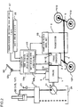
- FIG. 2 shows a schematic diagram of a control system of the wheel loader equipped with the engine control device according to the first embodiment of the present invention.
- An input shaft of a torque converter 2 is coupled to an output shaft of an engine 1, and an output shaft of the torque converter 2 is coupled to a transmission 3.
- the torque converter 2 is a well-known fluid clutch that is constituted with an impeller, a turbine, and a stator, and rotation of the engine 1 is transmitted to the transmission 3 through the torque converter 2.
- the transmission 3 includes a hydraulic clutch that shifts the speed stage to one of first speed through fourth speed, and a rotation speed of the output shaft of the torque converter 2 is changed via the transmission 3. Rotation after the speed change is transmitted to the wheels 113 and 123 through a propeller shaft 4 and axles 5, and thus the wheel loader 100 travels.
- a variable displacement hydraulic pump 11 for work is driven by the engine 1 and discharges pressure oil.
- the discharged oil from the hydraulic pump 11 is guided to a work actuator 30 via a control valve 21, and thus, the work actuator 30 is driven.
- the control valve 21 is operated by a control lever 31, and controls the flow of the pressure oil from the hydraulic pump 11 to the actuator 30.
- the control lever 31 represents an arm control lever or a bucket control lever
- the actuator 30 represents the arm cylinder 117 or the bucket cylinder 115
- the control valve 21 represents an arm control valve or a bucket control valve, for the sake of simplicity.
- the actuator 30 corresponds to the arm cylinder 117 and the control valve 21 corresponds to the arm control valve.
- the actuator 30 corresponds to the bucket 115 and the control valve 21 corresponds to the bucket control valve.
- the displacement of the pump is changed by a well-known regulator (not shown).
- the regulator changes the pump displacement according to the pump discharge pressure so as, for instance, to perform a fixed torque control for setting a work torque to be constant.
- a fixed displacement pump such as a gear pump or the like, may be employed as the hydraulic pump 11.
- the arm control lever corresponding to the control lever 31 is an operating member for operating the arm 111 and outputs a command for raising/lowering the arm 111.
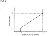
- FIG. 3 shows relationship between a lever operation amount L of the control lever 31 and a pilot pressure p.
- the arm control lever is a hydraulic pilot type operating lever that outputs a pilot pressure p according to a lever operation amount L as shown in FIG. 3 .
- the pilot pressure p does not increase when the lever operation amount L is less than a minimum lever operation amount La, and the pilot pressure p is increased to pa when the lever operation amount L becomes the minimum lever operation amount La.
- the control valve 21 (the arm control valve) is controlled to be switched over when the pilot pressure is equal to or greater than pa, taking into account the dead band of the arm control lever.
- a pilot pressure pb is a pressure value corresponding to a maximum lever operation amount Lb of the arm control lever.
- the pilot pressure p increases in proportion to the lever operation amount L if the lever operation amount L is within a range between the minimum lever operation amount La and the maximum lever operation amount Lb.
- the bucket control lever is also a hydraulic pilot type operating lever, similar to the arm control lever, that outputs a command for tilting/dumping the bucket 112.
- the torque converter 2 has a function to increase output torque with respect to input torque, i.e., a function to make a torque ratio 1 or greater.
- e output rotation speed No/input rotation speed Ni
- the rotation speed No of the output shaft 22 of the torque converter 2 decreases, i.e., the vehicle speed decreases and the torque converter speed ratio e is reduced. Since, at the same time, the torque ratio increases, the vehicle can travel with a greater driving force for travelling (i.e. traction force).
- the torque converter speed ratio e shows a positive value when a rotation direction of the input shaft of the torque converter 2 is the same as that of the output shaft of the torque converter, whereas the torque converter speed ratio e is a negative value when the rotation directions of the input shaft and the output shaft are different from one another. Therefore, the speed ratio e shows a negative value when the vehicle travels in a direction opposite to a direction instructed through a forward/reverse switching over switch 17 (when traveling in an opposite direction). It is to be noted that the speed ratio e becomes equal to or greater than 1 when an accelerator pedal 52 is eased off while traveling on level ground or when the vehicle travels downhill without requiring a driving force.
- a controller 10 is configured to include an arithmetic processing unit that includes a CPU, a ROM, a RAM, other peripheral circuits, and the like. Signals from a rotation speed detector 14 that detects the rotation speed Ni of the input shaft of the torque converter 2, a rotation speed detector 15 that detects the rotation speed No of the output shaft of the torque converter 2, and a shift switch 18 that indicates an upper limit of the speed stage among the first speed through the fourth speed are input to the controller 10.
- the controller 10 is connected with an accelerator operation amount detector 52a that detects a pedal operation amount S of the accelerator pedal 52, and an engine rotation speed sensor 13 that detects an actual rotation speed Na of the engine 1 and outputs an actual rotation speed signal to the controller 10.
- the controller 10 includes a target rotation speed setting unit 10a, embodied as a functional unit, that sets a target engine rotation speed Nt of the engine 1 depending on the pedal operation amount S of the accelerator pedal 52 detected by the accelerator operation amount detector 52a.
- the controller 10 outputs a control signal corresponding to the target engine rotation speed Nt set by the target rotation speed setting unit 10a to an engine controller 9 so as to control the actual rotation speed (number of rotations) of the engine 1.
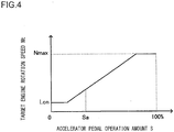
- FIG. 4 shows relationship between the pedal operation amount S of the accelerator pedal 52 and the target engine rotation speed Nt.
- the target engine rotation speed Nt increases as the pedal operation amount S of the accelerator pedal 52 increases, and the target engine rotation speed Nt becomes a rated rotation speed Nmax (for example, 2000 rpm) when the accelerator pedal is depressed to a full extent.
- the controller 10 outputs the control signal corresponding to this target engine rotation speed Nt to the engine controller 9 so as to control the actual rotation speed Na of the engine 1 to the target engine rotation speed Nt.
- the operator wishes to increase the vehicle speed or travel driving force, he/she increases the pedal operation amount S of the accelerator pedal 52 so as to raise the engine rotation speed.
- the engine controller 9 compares the actual rotation speed Na of the engine 1 detected by the engine rotation speed sensor 13 with the target engine rotation speed Nt input from the controller 10 and controls a fuel injection system (not shown) so as to bring the actual rotation speed Na of the engine 1 close to the target engine rotation speed Nt.
- the controller 10 determines whether or not the pedal operation amount S from the accelerator operation amount detector 52a is smaller than a predetermined value Sa.
- the predetermined value Sa is set as a threshold value that indicates the accelerator pedal 52 is hardly stepped on, and is stored in advance in the ROM or RAM in the controller 10.
- the controller 10 is connected with the forward/reverse switching over switch 17 that instructs the forward travel or the reverse travel for the vehicle and the controller 10 detects an operating position (forward (F)/ neutral (N)/ reverse (R)) of the forward/reverse switching over switch 17.
- the controller 10 outputs to a transmission solenoid control unit 20 a control signal for engaging a forward clutch (not shown) in the transmission 3 when the forward/reverse switching over switch 17 is switched to the forward (F) position.
- the controller 10 outputs to the transmission solenoid control unit 20 a control signal for engaging a reverse clutch (not shown) in the transmission 3 when the forward/reverse switching over switch 17 is switched to the reverse (R) position.
- a clutch control valve (not shown) provided in the transmission solenoid control unit 20 increases clutch pressure for operating the forward clutch or the reverse clutch (not shown).
- the forward clutch or the reverse clutch (not shown) is engaged, and thus a travel direction of the work vehicle is switched to the forward direction or to the reverse direction.
- the controller 10 When the forward/reverse switching over switch 17 is switched to the neutral (N) position, the controller 10 outputs to the transmission solenoid control unit 20 a control signal for releasing the forward clutch and the reverse clutch (not shown).
- the clutch control valve (not shown) provided in the transmission solenoid control unit 20 reduces the clutch pressure for operating the forward clutch and the reverse clutch (not shown). As a result, the forward clutch and the reverse clutch are released and the transmission 3 enters into the neutral state.
- FIG. 5 is an illustration that shows V-shape loading, which is one of the methods to load soil or the like onto a dump truck.
- V-shape loading firstly, as indicated by an arrow a, the wheel loader 100 moves forward and scoops soil or the like.
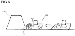
- FIG. 6 illustrates excavation work with the wheel loader 100.
- the bucket 112 is dug into a mound 130 of the soil or the like, and then the arm 111 is raised after operating the bucket 112 or the bucket 112 and the arm 111 are operated simultaneously and finally the arm 111 only is raised.
- the wheel loader 100 is once moved backward as indicated by an arrow b in FIG. 5 when the excavation work ends. As indicated by an arrow c, the wheel loader 100 moves forward to the dump truck, stops short of the dump truck, loads the scooped soil or the like onto the dump truck, and as indicated by an arrow d, the wheel loader 100 moves backward to the original position.
- the above is a basic operation of the V-shape loading method.
- the accelerator pedal 52 may be released and stepped on repeatedly and alternately with the bucket 112 dug into the mound while the control lever 31, such as the arm control lever or the bucket control lever, is being operated so as to fill the bucket 112 with the soil or the like.
- the engine output torque may become insufficient to drive a front work device configured by including the arm 111 and the bucket 112 when operating the control lever 31, such as the arm control lever or the bucket control lever, in a state where the accelerator pedal 52 is eased off, and as a result, the engine may be stalled.
- the rotation speed of the engine 1 is controlled as described below.
- the controller 10 includes a target rotation speed correction unit 10b, embodied as a functional unit.
- the target rotation speed correction unit 10b corrects the target engine rotation speed Nt set by the target rotation speed setting unit 10a to be increased based on the torque converter speed ratio e when the pedal operation amount S of the accelerator pedal 52 is smaller than the predetermined value Sa and the torque converter speed ratio e calculated by the controller 10 is less than a predetermined value e1 which falls in a range equal to or greater than 0 and less than 1.
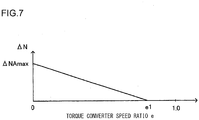
- FIG. 7 shows relationship between the torque converter speed ratio e and an increase amount ⁇ N in the rotation speed.
- ⁇ N is 0 when the torque converter speed ratio e is equal to or greater than the predetermined value e1 (for example, 0.8) (e ⁇ e1) which falls in the range equal to or greater than 0 and less than 1.
- the rotation speed increase amount ⁇ N increases from 0 to an upper limit value ⁇ NAmax (for example, 100 rpm) in proportion to decrease in the torque converter speed ratio e when the torque converter speed ratio e is within the range equal to or greater than 0 and less than e1 (0 ⁇ e ⁇ e1).
- the characteristic shown in FIG. 7 is stored in advance in the ROM or the RAM in the controller 10.
- the target rotation speed correction unit 10b corrects the target engine rotation speed Nt so as to increase the rotation speed by a greater extent as the load is greater by increasing the increase amount in the target engine rotation speed Nt with decrease in the torque converter speed ratio e in accordance with the characteristic as shown in FIG. 7 .
- a state in which the torque converter speed ratio e is equal to or greater than e1 (e ⁇ e1) is defined as a normal state
- a state in which the torque converter speed ratio e is within the range which is equal to or greater than 0 and less than e1 (0 ⁇ e ⁇ e1) is defined as a load increase state.
- the torque converter speed ratio e In a combined stall state during the excavation work, the torque converter speed ratio e is extremely close to 0.
- the torque converter speed ratio e during a forward travel on an uphill is greater than the torque converter speed ratio e during the excavation work but still smaller than e1.
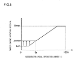
- FIG. 8 shows relationship between the pedal operation amount S of the accelerator pedal 52 and the target engine rotation speed Nt.
- a characteristic in the normal state is indicated by a broken line and a corrected characteristic (with a maximum value Loamax) by which the target engine rotation speed Nt is increased in the load increase state is indicated by a solid line.
- FIG. 9 is a travel performance diagram (torque diagram) representing relation between the engine rotation speed and torque.
- a characteristic f1 represents an engine output torque
- characteristics f2 C0, C1 represent input torque of the torque converter 2 when the torque converter speed ratio e is 0 and e1, respectively.
- the torque converter input torque increases in proportion to a square of the rotation speed Ni of the torque converter input shaft, and the torque converter input torque decreases as the torque converter speed ratio e becomes greater.
- the matching point shifts from MP1 to MP2 if the low idle rotation speed Lo is increased by the maximum increase amount ⁇ NAmax.
- an extent of rising (TAi - TNi) by which the torque converter input torque is increased when the low idle rotation speed Lo is increased by the maximum increase amount ⁇ NAmax is smaller than an extent of rising (TAo - TNo) by which the engine output torque is increased.
- a pump absorption torque that can be used in a hydraulic circuit of excavation system can be increased by correcting and increasing the low idle rotation speed Lo.
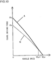
- FIG. 10 shows relationship between a vehicle creep speed and a travel driving force.
- both of the characteristics represent characteristics at the second speed as an example.
- the travel driving force is larger at a lower speed (low-speed-high-torque), and the travel driving force is smaller at a faster speed (high-speed-low-torque) for both of the characteristics N and A.
- the travel driving force at a time of creeping with the low idle rotation speed Lo corrected and increased (hereafter, it may be simply referred to as "with correction”) is larger than the travel driving force at a time of creeping in the normal state (without correction), and a difference therebetween becomes smaller as the vehicle speed increases.
- the difference between the travel driving forces is the greatest at a time of stall, and a travel driving force Fa with correction, for instance, is approximately 1.2 times greater than a travel driving force Fn in the normal state.
- the characteristic N and the characteristic A coincide with one another when the vehicle speed is equal to or greater than VLo1 and equal to or smaller than VLo, and a maximum vehicle speed when creep traveling is a predetermined value VLo for both of the characteristics N and A.
- the characteristic N and the characteristic A match with one another in the range of the vehicle speed equal to or greater than VLo1 and equal to or smaller than VLo because the rotation speed increase amount ⁇ N is 0 when the torque converter speed ratio e is equal to or larger than e1 as shown in FIG. 7 .
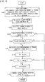
- Target rotation speed correction control will now be explained with reference to a flowchart of FIG. 11 .
- FIG. 11 is a flowchart that shows operation of engine rotation speed increase correction process in the engine control device according to the first embodiment of the present invention.
- a program enabling the processing shown in FIG. 11 is started up as an ignition switch (not shown) is turned on, and the processing is subsequently executed repeatedly by the controller 10.
- ignition on refers to an action of turning on the ignition key and operating it to an operating position
- ignition off' refers to an action of operating the ignition key to a stopping position
- step S100 information on the pedal operation amount S of the accelerator pedal 52 detected by the accelerator operation amount detector 52a, information on the rotation speed Ni of the input shaft of the torque converter 2 detected by the rotation speed detector 14 and information on the rotation speed No of the output shaft of the torque converter 2 detected by the rotation speed detector 15 are obtained, and then the processing proceeds to step S110.
- step S110 the target rotation speed setting unit 10a calculates the target engine rotation speed Nt corresponding to the pedal operation amount S detected by the accelerator operation amount detector 52a based on the characteristic shown in FIG. 4 which is stored in advance in the ROM or the RAM in the controller 10, and then the processing proceeds to step 120.
- step 120 the controller 10 calculates the torque converter speed ratio e by using the signals from the rotation speed detectors 14 and 15, and then the processing proceeds to step S130.
- step S130 it is determined whether or not the pedal operation amount S obtained in step S100 is smaller than the predetermined threshold value Sa. If affirmative decision is made in step S130, the processing proceeds to step S140 and correction process for increasing the target engine rotation speed Nt based on the torque converter speed ratio e is executed (step S140 to step S170) as described later. If negative decision is made in step S130, the processing proceeds to step S180 without correcting the target engine rotation speed Nt.
- step S180 the controller 10 outputs the control signal to the engine controller 9 so as to control the actual rotation speed Na of the engine 1 to the target engine rotation speed Nt. If negative decision is made in step S130, the actual rotation speed Na of the engine 1 is controlled to the target engine rotation speed Nt corresponding to the pedal operation amount S of the accelerator pedal 52 set by the target rotation speed Nt (see FIG. 4 ) in step S180.
- step S130 If it is determined in step S130 that the pedal operation amount S is smaller than the threshold value Sa, the target rotation speed correction unit 10bcalculates in step S140 the rotation speed increase amount ⁇ N for correction according to the torque converter speed ratio e based on the predefined characteristic in FIG. 7 .
- step S150 the target rotation speed correction unit 10b adds ⁇ N obtained in step S140 to the target engine rotation speed Nt calculated in step S110 and sets the calculated value as a new target engine rotation speed Nt, and then the processing proceeds to step S160. In other words, in step S150, the target engine rotation speed Nt calculated in step S110 is corrected to be increased.
- step S160 it is determined whether or not the reset, that is, corrected target engine rotation speed Nt is larger than the maximum low idle rotation speed Loamax. If affirmative decision is made in step S160, the processing proceeds to step S170, whereas the processing proceeds to step S180 if negative decision is made.
- step S170 the maximum low idle rotation speed Loamax is set as the target engine rotation speed Nt.
- the maximum value of the target engine rotation speed Nt is limited to the maximum low idle rotation speed Loamax when the pedal operation amount S of the accelerator pedal 52 is equal to or greater than 0 and less than Sa.
- step S180 the controller 10 outputs the control signal to the engine controller 9 so as to control the actual rotation speed Na of the engine 1 to the target engine rotation speed Nt as described above. If affirmative decision is made in step S130, the actual rotation speed Na of the engine 1 is controlled to the target rotation speed Nt (see FIG. 8 ) corrected by the target rotation speed correction unit 10b in step 180.
- the operations in the first embodiment are summarized below.
- the operator switches the forward/reverse switching over switch 17 to the forward position and steps on the accelerator pedal 52 to generate the travel driving force corresponding to the pedal operation amount S so as to allow the wheel loader 100 to move toward the mound 130.
- the traveling load increases and the torque converter speed ratio e decreases as the bucket 112 is dug into the mound 130.
- the target engine rotation speed Nt decreases.
- the torque converter speed ratio e is smaller than the predetermined value e1
- the rotation speed increase amount ⁇ N according to the characteristic as shown in FIG. 7 is added to the target engine rotation speed Nt according to the characteristic as shown in FIG. 4 .
- the engine rotation speed is corrected so that the target engine rotation speed Nt which is set according to the pedal operation amount S in the normal state is increased by ⁇ N, and the engine controller 9 controls the actual engine rotation speed Na to the corrected target engine rotation speed Nt (step S130 to step S180). In this manner, it is possible to prevent the actual engine rotation speed Lo from being reduced to Lon when the accelerator pedal 52 is eased off while the bucket 112 is dug into the mound 130.
- the engine output torque is raised as shown in FIG. 9 so that it is possible to prevent the engine stall even if the front work device is activated in response to the operation of the control lever 31 after the accelerator pedal 52 is eased off with the bucket 112 dug into the mound 130.
- the accelerator pedal 52 has to be stepped on minutely in order to allow the vehicle to travel forward at a slow speed or to stop the vehicle with the low idle rotation speed.
- the number of times of operating the accelerator pedal 52 tends to increase, causing the drive operation on an uphill to be complicated.
- the creep speed may be increased in an undesired manner, and thus, a brake pedal (not shown) has to be operated to keep the vehicle to travel at a slow speed.
- a brake pedal (not shown) has to be operated to keep the vehicle to travel at a slow speed.
- the operator is required to perform onerous, troublesome operations, causing the operator to fatigue.
- the low idle rotation speed is set to be higher as the torque converter speed ratio e is smaller. In this manner, the low idle rotation speed is increased by a greater extent as an angle of slope at an uphill is greater, and as a result, it is possible to prevent the creep speed from becoming too fast on a gentle upslope and also to prevent the vehicle from rolling back on a steep uphill.
- By increasing the low idle rotation speed by a greater extent as the torque converter speed ratio e is smaller during the excavation work it is ensured that the engine stall attributable to operations at the front work device can be prevented.
- FIGS. 12 to 14 An engine control device according to a second embodiment will now be explained with reference to FIGS. 12 to 14 .
- members identical to or equivalent to the members described in the first embodiment are assigned with the same reference numerals as the first embodiment, and the following explanation will focus on the differences from the first embodiment.
- FIG. 12 shows a schematic diagram of a control system of the wheel loader equipped with the engine control device according to the second embodiment of the present invention.
- the wheel loader equipped with the engine control device according to the second embodiment further includes a pilot pressure sensor 219 for detecting that the front work device has been operated, in addition to the structure as described in the first embodiment.
- the target rotation speed correction unit 10b corrects the target engine rotation speed Nt set with the target rotation speed setting unit 10a to be increased based on the torque converter speed ratio e, further taking into account the operation at the front work device detected by the pilot pressure sensor 219.
- a signal from the pilot pressure sensor 219 is input to the controller 10.
- the pilot pressure sensor 219 detects a pilot pressure p indicating the lever operation amount L of the control lever 31 and outputs a lever signal to the controller 10. It is to be noted that although the pilot pressure sensor 219 is provided for each of the arm control lever and the bucket control lever which are represented as the control lever 31, FIG. 2 shows only one pilot pressure sensor 219 provided for one of the control levers as a representative example.
- FIG. 13 shows relationship between lever operation amount L of the control lever and pilot pressure p.
- the controller 10 determines whether or not the pilot pressure p is equal to or greater than a predetermined value p1 based on the signal from the pilot pressure sensor 219.
- the predetermined value p1 is defined as a value in a range which is equal to or greater than 0 and equal to or smaller than pa as shown in FIG. 13 , and is stored in advance in the ROM or the RAM in the controller 10 as a threshold value for judging that the front work device has been operated.
- FIG. 14 is a flowchart that shows operation of engine rotation speed increase correction process executed in the engine control device according to the second embodiment of the present invention, and in the flowchart, step S235 is added to the flowchart shown in FIG. 11 and step S100 in the flowchart in FIG. 11 is replaced with step S200.
- step S200 information on the pilot pressure p detected by the pilot pressure sensor 219 is obtained in step S200, in addition to the information on the pedal operation amount S of the accelerator pedal 52 detected by the accelerator operation amount detector 52a, the information on the rotation speed Ni of the input shaft of the torque converter 2 detected by the rotation speed detector 14, and the information on the rotation speed No of the output shaft of the torque converter 2 detected by the rotation speed detector 15, and then the processing proceeds to step S110.
- step S235 it is determined whether or not the pilot pressure p is equal to or greater than p1. If affirmative decision is made in step S235, the processing proceeds to step S140 in which the process for correcting the target engine rotation speed Nt to be increased based on the torque converter speed ratio e is executed as explained in the first embodiment (step S1 40 to step S170). If negative decision is made in step S235, the processing proceeds to step S180 without correcting the target engine rotation speed Nt.
- the following advantage (6) is achieved in addition to the advantages (1) and (4) achieved in the first embodiment. (6) Since the target engine rotation speed Nt is increased only when the operation of the front work device is detected, a frequency with which the actual engine rotation speed Na is increased can be reduced to the minimum necessary number and fuel consumption can be reduced.
- FIGS. 15 to 18 An engine control device according to a third embodiment will now be explained with reference to FIGS. 15 to 18 .
- members identical to or equivalent to the members described in the first embodiment are assigned with the same reference numerals as the first embodiment, and the following explanation will focus on the differences from the first embodiment.
- the wheel loader equipped with the engine control device according to the third embodiment includes the same structure as that of the first embodiment (see FIGS. 1 and 2 ).
- FIG. 15 shows characteristics of the rotation speed increase amount ⁇ N according to the torque converter speed ratio e stored in the ROM or the RAM in the controller 10 of the engine control device according to the third embodiment of the present invention.
- the characteristic of the rotation speed increase amount ⁇ N corresponding to the torque converter speed ratio e as described in the first embodiment is indicated by a two-dot chain line.
- the characteristic of ⁇ N is such that ⁇ N increases from 0 to the upper limit value ⁇ NAmax (for example, 100 rpm) in proportion to decrease in the torque converter speed ratio e in the range of the torque converter speed ratio e which is equal to or greater than 0 and less than e1 (0 ⁇ e ⁇ e1).
- ⁇ NAmax for example, 100 rpm
- ⁇ N is 0 when the torque converter speed ratio e is equal to or greater than e1
- ⁇ N increases from 0 to an upper limit value ⁇ NBmax (for example, 50 rpm) in proportion to decrease in the torque converter speed ratio e when the torque converter speed ratio e is equal to or greater than e2 and less than e1 (e2 ⁇ e ⁇ e1).
- the rotation speed increase amount ⁇ N is at the maximum value ⁇ NBmax when the torque converter speed ratio e is equal to or greater than 0 and less than e2 (for example, 0.7) (0 ⁇ e ⁇ e2).
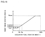
- FIG. 16 shows relationship between the pedal operation amount S of the accelerator pedal 52 and the target engine rotation speed Nt.
- a characteristic in the normal state is indicated by a broken line and a corrected characteristic (with a maximum value Lobmax) by which the target engine rotation speed Nt is increased in the load increase state is indicated by a solid line.
- the maximum low idle rotation speed Loamax after increase correction as explained in the first embodiment is indicated by a two-dot chain line.
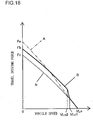
- FIG. 17 is a travel performance diagram (torque diagram) representing relation between the engine rotation speed and torque.
- a characteristic f1 represents an engine output torque
- characteristics f2 C0, C1, C2
- an extent of rising (TBi - TNi) by which the torque converter input torque is increased when the low idle rotation speed Lo is increased by the maximum increase amount ⁇ NBmax is smaller than an extent of rising (TBo - TNo) by which the engine output torque is increased.
- a pump absorption torque that can be used in a hydraulic circuit of excavation system can be increased by correcting and increasing the low idle rotation speed Lo.
- FIG, 18 shows relationship between the vehicle creep speed and the travel driving force.
- both of the characteristics represent characteristics at the second speed as an example.
- the travel driving force is larger at a lower speed (low-speed-high-torque), and the travel driving force is smaller at a faster speed (high-speed-low-torque) for both of the characteristics N and B.
- the travel driving force at a time of creep traveling with the low idle rotation speed Lo corrected and increased is larger than the travel driving force at a time of creep traveling in the normal state (without correction).
- a travel driving force Fb with correction is approximately 1.1 times greater than a travel driving force Fn in the normal state.
- a maximum vehicle speed when creep traveling is a predetermined value VLo for both of the characteristics N and B.
- the characteristic B corresponds with the characteristic of the rotation speed increase amount ⁇ N depending on the torque converter speed ratio e as shown in FIG. 15 .
- the characteristic B and the characteristic N coincide with one another.
- the travel driving force of the characteristic B becomes greater as the vehicle speed decreases, as compared with the characteristic N.
- the traveling drive force of the characteristic B is larger than the characteristic N by a constant amount.
- step S130 in place of step S130 in the flowchart of FIG. 11 , it is determined whether or not correction based on the torque converter speed ratio e is to be executed by judging whether the accelerator pedal operation amount S is less than Sb or not.
- the increase amount ⁇ N for the target engine rotation speed Nt is increased as the torque converter speed ratio e decreases according to the characteristic shown in FIG. 15 , in place of the characteristic shown in FIG. 7 in the first embodiment. Even if the rotation speed increase amount ⁇ N is set to be constant when the torque converter speed ratio e is equal to or greater than 0 and less than e2 in the third embodiment, the advantages (1) to (4) can be achieved as in the first embodiment.
- the wheel loader equipped with the engine control device according to the fourth embodiment includes the structure as described in the third embodiment (see FIGS. 1 and 2 ).
- the target engine rotation speed Nt is corrected by increasing the increase amount ⁇ N in the target engine rotation speed Nt as the torque converter speed ratio e decreases in accordance with the characteristic indicated in FIG. 15 as described in the third embodiment.
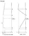
- FIG. 19 shows time charts illustrating operation for stopping the wheel loader that is creeping or traveling slowly and operation for creep starting the vehicle that is in the stopped state, with the wheel loader equipped with the engine control device according to the fourth embodiment of the present invention.
- the controller 10 gradually increases the actual rotation speed Na of the engine 1 toward the target engine rotation speed Nt corrected by the target rotation speed correction unit 10b. If, after the target engine rotation speed Nt is corrected by the target rotation speed correction unit 10b, the target engine rotation speed Nt according to the pedal operation amount S at the accelerator pedal 52, that is, a target engine rotation speed without correction, is set again by the target rotation speed setting unit 10a, the controller 10 decreases the actual rotation speed Na of the engine 1 immediately to the target engine rotation speed Nt set by the target rotation speed setting unit 10a.
- FIG. 19(a) is a schematic diagram showing a time series variation in the target engine rotation speed Nt
- FIG. 19(b) is a schematic diagram showing a time series variation in the vehicle speed.
- the actual rotation speed Na of the engine 1 varies following the target engine rotation speed Nt set by the target rotation speed setting unit 10a.
- a brake pedal (not shown) is operated so as to activate a well-known service brake device (not shown) from the time point t1 to a time point t5
- the target engine rotation speed Nt is set to Lon from the time point t1 to a time point t2.
- the target engine rotation speed Nt is corrected to be increased.
- the target engine rotation speed Nt is corrected or calculated to be Lobmax.
- the controller 10 sets the target engine rotation speed Nt to be increased gradually toward Lobmax over time (approximately over1 to 1.5 seconds) so that the target engine rotation speed Nt reaches Lobmax at a time point t4.
- the vehicle speed decreases gradually from the time point t1 to a time point t3 and becomes 0 at the time point t3.
- the vehicle starts creeping upon release of the brake pedal (not shown) at the time point t5.
- the controller 10 sets the target engine rotation speed Nt to Lon at once at the time point t5 so as to decrease the actual rotation speed Na of the engine 1 immediately to Lon.
- the vehicle speed increases smoothly from the time point t5, and reaches a predetermined speed (the creep speed maximum value VLo) at a time point t7.
- FIG. 20 shows a comparison example to FIG. 19 .
- the controller 10 instantly sets the target engine rotation speed Nt to the corrected rotation speed Lbmax at the time point t2.
- the target engine rotation speed Nt is set to the corrected, increased value at once at the time point t2
- the actual rotation speed Na of the engine 1 is increased sharply and decrease in the vehicle speed is interrupted temporarily so that the vehicle will be subjected to a great shock. Since the actual rotation speed Na of the engine 1 rises abruptly, a stopping distance of the vehicle is prolonged and the vehicle stops at the time point t4.
- the torque converter speed ratio e becomes e1 or more at the time point t5, and thus, the target engine rotation speed Nt is again set to the target engine rotation speed Nt corresponding to the operation amount of the accelerator pedal 52 at the time point t5.
- the following advantages (7) and (8) are achieved in addition to the advantages (1) to (4) as in the first embodiment.
- the present invention also includes the following variations, and one or more of the variations can be combined with any of the embodiments described above.
- a pump pressure sensor (not shown) for detecting a pump discharge pressure Pp at the hydraulic pump 11 may be provided so as to detect that the front work device has been operated based on the pump discharge pressure Pp input to the controller 10 from the pump pressure sensor, and the correction control of the target engine rotation speed Nt may be executed based on the accelerator pedal operation amount S and the torque converter speed ratio e.
- step S200 in place of step S200 in the flowchart in FIG.
- step S110 the information on the pedal operation amount S of the accelerator pedal 52 detected by the accelerator operation amount detector 52a, the information on the rotation speed Ni of the input shaft of the torque converter 2 detected by the rotation speed detector 14, the information on the rotation speed No of the output shaft of the torque converter 2 detected by the rotation speed detector 15, and information on the pump pressure Pp detected by the pump pressure sensor are obtained, and then the processing proceeds to step S110.
- the controller 10 may execute processing for judging whether or not the pump pressure Pp is equal to or greater than a predetermined value Pp1, and if affirmative judgment is made, the processing proceeds to step S140 whereas the processing proceeds to step S180 if negative judgment is made.
- the predetermined value Pp1 (for instance, 5 MPa) is stored in advance in the ROM or the RAM in the controller 10 as a threshold value representing that the front work device has been operated.
Landscapes
- Engineering & Computer Science (AREA)
- Mechanical Engineering (AREA)
- General Engineering & Computer Science (AREA)
- Chemical & Material Sciences (AREA)
- Combustion & Propulsion (AREA)
- Transportation (AREA)
- Control Of Vehicle Engines Or Engines For Specific Uses (AREA)
- Operation Control Of Excavators (AREA)
- Combined Controls Of Internal Combustion Engines (AREA)
Applications Claiming Priority (2)
| Application Number | Priority Date | Filing Date | Title |
|---|---|---|---|
| JP2012021749A JP5808686B2 (ja) | 2012-02-03 | 2012-02-03 | 作業車両のエンジン制御装置 |
| PCT/JP2013/052510 WO2013115399A1 (ja) | 2012-02-03 | 2013-02-04 | 作業車両のエンジン制御装置 |
Publications (3)
| Publication Number | Publication Date |
|---|---|
| EP2811139A1 EP2811139A1 (en) | 2014-12-10 |
| EP2811139A4 EP2811139A4 (en) | 2016-01-27 |
| EP2811139B1 true EP2811139B1 (en) | 2019-05-08 |
Family
ID=48905423
Family Applications (1)
| Application Number | Title | Priority Date | Filing Date |
|---|---|---|---|
| EP13743737.2A Active EP2811139B1 (en) | 2012-02-03 | 2013-02-04 | Engine control device for work vehicle |
Country Status (4)
| Country | Link |
|---|---|
| US (1) | US9523315B2 (ja) |
| EP (1) | EP2811139B1 (ja) |
| JP (1) | JP5808686B2 (ja) |
| WO (1) | WO2013115399A1 (ja) |
Families Citing this family (10)
| Publication number | Priority date | Publication date | Assignee | Title |
|---|---|---|---|---|
| KR102089738B1 (ko) * | 2012-08-01 | 2020-03-17 | 데쿠세리아루즈 가부시키가이샤 | 이방성 도전 필름의 제조 방법, 이방성 도전 필름, 및 접속 구조체 |
| US9650760B2 (en) | 2013-12-03 | 2017-05-16 | Komatsu Ltd. | Work vehicle |
| JP6200792B2 (ja) * | 2013-12-09 | 2017-09-20 | 株式会社Kcm | 作業車両のエンジン制御装置 |
| US9423026B2 (en) * | 2013-12-20 | 2016-08-23 | Cnh Industrial America Llc | System and method for controlling a continuously variable transmission when transitioning operation from a hydrostatic mode to a hydro-mechanical mode |
| JP6823500B2 (ja) * | 2017-03-03 | 2021-02-03 | 株式会社小松製作所 | 作業車両および制御方法 |
| DE102017203835A1 (de) * | 2017-03-08 | 2018-09-13 | Zf Friedrichshafen Ag | Verfahren zum Ermitteln einer Soll-Drehzahl einer Antriebsmaschine einer Arbeitsmaschine mit einem Stufenlosgetriebe und mit einer Arbeitshydraulik |
| JP6963961B2 (ja) * | 2017-10-12 | 2021-11-10 | 株式会社小松製作所 | 作業車両及び作業車両の制御方法 |
| CN110529265B (zh) * | 2019-09-05 | 2022-05-13 | 广西玉柴机器股份有限公司 | 柴油机多档位恒定转速的控制方法 |
| CN114174600B (zh) * | 2020-03-23 | 2023-05-12 | 日立建机株式会社 | 作业车辆 |
| GB2600964B (en) * | 2020-11-13 | 2023-02-01 | Cummins Inc | Systems and methods for controlling vehicle speed for a vehicle with a torque convertor |
Family Cites Families (18)
| Publication number | Priority date | Publication date | Assignee | Title |
|---|---|---|---|---|
| JP3209104B2 (ja) * | 1996-07-30 | 2001-09-17 | トヨタ自動車株式会社 | エンジンおよび自動変速機を備えた車両の制御装置 |
| JP4394308B2 (ja) * | 2001-06-26 | 2010-01-06 | 株式会社小松製作所 | 車両のエンジン制御装置 |
| JP4484467B2 (ja) * | 2003-08-01 | 2010-06-16 | 日立建機株式会社 | 走行式油圧作業機 |
| JP4493990B2 (ja) * | 2003-11-26 | 2010-06-30 | 日立建機株式会社 | 走行式油圧作業機 |
| JP4315248B2 (ja) * | 2004-12-13 | 2009-08-19 | 日立建機株式会社 | 走行作業車両の制御装置 |
| JP4812309B2 (ja) * | 2005-02-15 | 2011-11-09 | トヨタ自動車株式会社 | 内燃機関の制御装置 |
| US7516007B2 (en) | 2005-09-23 | 2009-04-07 | Gm Global Technology Operations, Inc. | Anti-rollback control for hybrid and conventional powertrain vehicles |
| JP4389877B2 (ja) * | 2006-01-18 | 2009-12-24 | トヨタ自動車株式会社 | 車両に搭載された内燃機関の推定トルク算出装置 |
| JP2007237925A (ja) * | 2006-03-08 | 2007-09-20 | Toyota Motor Corp | 車両および駆動装置並びにこれらの制御方法 |
| JP4705598B2 (ja) * | 2007-03-14 | 2011-06-22 | 住友建機株式会社 | 建設機械のエンジン回転数制御装置 |
| JP4714721B2 (ja) * | 2007-09-19 | 2011-06-29 | 日立建機株式会社 | 走行式油圧作業機 |
| US8315783B2 (en) * | 2007-10-24 | 2012-11-20 | Hitachi Construction Machinery Co., Ltd. | Engine control device for working vehicle |
| JP5496454B2 (ja) | 2007-11-29 | 2014-05-21 | 日産自動車株式会社 | ハイブリッド車両の制御装置 |
| JP2009196393A (ja) * | 2008-02-19 | 2009-09-03 | Iseki & Co Ltd | 作業車両 |
| JP5124504B2 (ja) * | 2009-02-09 | 2013-01-23 | 日立建機株式会社 | 作業車両の原動機制御装置 |
| JP5164933B2 (ja) * | 2009-06-19 | 2013-03-21 | 日立建機株式会社 | 作業車両の制御装置 |
| JP5204726B2 (ja) * | 2009-06-19 | 2013-06-05 | 日立建機株式会社 | 作業車両の原動機制御装置 |
| JP2011122706A (ja) * | 2009-12-14 | 2011-06-23 | Hitachi Constr Mach Co Ltd | 作業車両のクラッチ制御装置 |
-
2012
- 2012-02-03 JP JP2012021749A patent/JP5808686B2/ja active Active
-
2013
- 2013-02-04 WO PCT/JP2013/052510 patent/WO2013115399A1/ja active Application Filing
- 2013-02-04 US US14/376,286 patent/US9523315B2/en active Active
- 2013-02-04 EP EP13743737.2A patent/EP2811139B1/en active Active
Non-Patent Citations (1)
| Title |
|---|
| None * |
Also Published As
| Publication number | Publication date |
|---|---|
| WO2013115399A1 (ja) | 2013-08-08 |
| US9523315B2 (en) | 2016-12-20 |
| JP5808686B2 (ja) | 2015-11-10 |
| US20140379243A1 (en) | 2014-12-25 |
| JP2013160116A (ja) | 2013-08-19 |
| EP2811139A4 (en) | 2016-01-27 |
| EP2811139A1 (en) | 2014-12-10 |
Similar Documents
| Publication | Publication Date | Title |
|---|---|---|
| EP2811139B1 (en) | Engine control device for work vehicle | |
| EP2444637B1 (en) | Working vehicle control apparatus | |
| JP5036824B2 (ja) | 作業車両の原動機制御装置 | |
| US8655557B2 (en) | Motor control device for working vehicle | |
| KR101882555B1 (ko) | 작업 차량의 엔진 제어 장치 | |
| EP2444634B1 (en) | Apparatus for controlling number of revolutions of engine for industrial vehicle | |
| US8775034B2 (en) | Shift control system for industrial vehicle | |
| JP5503954B2 (ja) | 作業車両のクラッチ制御装置 | |
| JP5237313B2 (ja) | 作業車両及び作業車両の制御方法 | |
| EP2824351B1 (en) | Working vehicle with driving force control | |
| KR101390138B1 (ko) | 산업 차량의 변속 제어 장치 | |
| US8668624B2 (en) | Motor control device for working vehicle | |
| JP5113946B1 (ja) | 作業車両及び作業車両の制御方法 | |
| WO2008066170A1 (fr) | Système de commande de changement de vitesse pour véhicule industriel | |
| US9037358B2 (en) | Wheel loader | |
| KR20090083425A (ko) | 산업 차량의 변속 제어 장치 | |
| EP2288759B1 (en) | A method for controlling a power source | |
| JP2011122706A (ja) | 作業車両のクラッチ制御装置 |
Legal Events
| Date | Code | Title | Description |
|---|---|---|---|
| PUAI | Public reference made under article 153(3) epc to a published international application that has entered the european phase |
Free format text: ORIGINAL CODE: 0009012 |
|
| 17P | Request for examination filed |
Effective date: 20140903 |
|
| AK | Designated contracting states |
Kind code of ref document: A1 Designated state(s): AL AT BE BG CH CY CZ DE DK EE ES FI FR GB GR HR HU IE IS IT LI LT LU LV MC MK MT NL NO PL PT RO RS SE SI SK SM TR |
|
| AX | Request for extension of the european patent |
Extension state: BA ME |
|
| DAX | Request for extension of the european patent (deleted) | ||
| RA4 | Supplementary search report drawn up and despatched (corrected) |
Effective date: 20160107 |
|
| RIC1 | Information provided on ipc code assigned before grant |
Ipc: F02D 29/00 20060101AFI20151222BHEP Ipc: F02D 45/00 20060101ALI20151222BHEP |
|
| RAP1 | Party data changed (applicant data changed or rights of an application transferred) |
Owner name: KCM CORPORATION |
|
| GRAP | Despatch of communication of intention to grant a patent |
Free format text: ORIGINAL CODE: EPIDOSNIGR1 |
|
| STAA | Information on the status of an ep patent application or granted ep patent |
Free format text: STATUS: GRANT OF PATENT IS INTENDED |
|
| INTG | Intention to grant announced |
Effective date: 20181130 |
|
| GRAS | Grant fee paid |
Free format text: ORIGINAL CODE: EPIDOSNIGR3 |
|
| GRAA | (expected) grant |
Free format text: ORIGINAL CODE: 0009210 |
|
| STAA | Information on the status of an ep patent application or granted ep patent |
Free format text: STATUS: THE PATENT HAS BEEN GRANTED |
|
| AK | Designated contracting states |
Kind code of ref document: B1 Designated state(s): AL AT BE BG CH CY CZ DE DK EE ES FI FR GB GR HR HU IE IS IT LI LT LU LV MC MK MT NL NO PL PT RO RS SE SI SK SM TR |
|
| REG | Reference to a national code |
Ref country code: GB Ref legal event code: FG4D |
|
| REG | Reference to a national code |
Ref country code: CH Ref legal event code: EP Ref country code: AT Ref legal event code: REF Ref document number: 1130471 Country of ref document: AT Kind code of ref document: T Effective date: 20190515 |
|
| REG | Reference to a national code |
Ref country code: DE Ref legal event code: R096 Ref document number: 602013055025 Country of ref document: DE |
|
| REG | Reference to a national code |
Ref country code: IE Ref legal event code: FG4D |
|
| REG | Reference to a national code |
Ref country code: SE Ref legal event code: TRGR |
|
| REG | Reference to a national code |
Ref country code: DE Ref legal event code: R082 Ref document number: 602013055025 Country of ref document: DE Representative=s name: MERH-IP MATIAS ERNY REICHL HOFFMANN PATENTANWA, DE Ref country code: DE Ref legal event code: R081 Ref document number: 602013055025 Country of ref document: DE Owner name: HITACHI CONSTRUCTION MACHINERY CO., LTD., JP Free format text: FORMER OWNER: KCM CORP., HYOGO, JP |
|
| REG | Reference to a national code |
Ref country code: NL Ref legal event code: MP Effective date: 20190508 |
|
| REG | Reference to a national code |
Ref country code: LT Ref legal event code: MG4D |
|
| PG25 | Lapsed in a contracting state [announced via postgrant information from national office to epo] |
Ref country code: AL Free format text: LAPSE BECAUSE OF FAILURE TO SUBMIT A TRANSLATION OF THE DESCRIPTION OR TO PAY THE FEE WITHIN THE PRESCRIBED TIME-LIMIT Effective date: 20190508 Ref country code: PT Free format text: LAPSE BECAUSE OF FAILURE TO SUBMIT A TRANSLATION OF THE DESCRIPTION OR TO PAY THE FEE WITHIN THE PRESCRIBED TIME-LIMIT Effective date: 20190908 Ref country code: ES Free format text: LAPSE BECAUSE OF FAILURE TO SUBMIT A TRANSLATION OF THE DESCRIPTION OR TO PAY THE FEE WITHIN THE PRESCRIBED TIME-LIMIT Effective date: 20190508 Ref country code: HR Free format text: LAPSE BECAUSE OF FAILURE TO SUBMIT A TRANSLATION OF THE DESCRIPTION OR TO PAY THE FEE WITHIN THE PRESCRIBED TIME-LIMIT Effective date: 20190508 Ref country code: LT Free format text: LAPSE BECAUSE OF FAILURE TO SUBMIT A TRANSLATION OF THE DESCRIPTION OR TO PAY THE FEE WITHIN THE PRESCRIBED TIME-LIMIT Effective date: 20190508 Ref country code: NO Free format text: LAPSE BECAUSE OF FAILURE TO SUBMIT A TRANSLATION OF THE DESCRIPTION OR TO PAY THE FEE WITHIN THE PRESCRIBED TIME-LIMIT Effective date: 20190808 Ref country code: FI Free format text: LAPSE BECAUSE OF FAILURE TO SUBMIT A TRANSLATION OF THE DESCRIPTION OR TO PAY THE FEE WITHIN THE PRESCRIBED TIME-LIMIT Effective date: 20190508 Ref country code: NL Free format text: LAPSE BECAUSE OF FAILURE TO SUBMIT A TRANSLATION OF THE DESCRIPTION OR TO PAY THE FEE WITHIN THE PRESCRIBED TIME-LIMIT Effective date: 20190508 |
|
| PG25 | Lapsed in a contracting state [announced via postgrant information from national office to epo] |
Ref country code: LV Free format text: LAPSE BECAUSE OF FAILURE TO SUBMIT A TRANSLATION OF THE DESCRIPTION OR TO PAY THE FEE WITHIN THE PRESCRIBED TIME-LIMIT Effective date: 20190508 Ref country code: RS Free format text: LAPSE BECAUSE OF FAILURE TO SUBMIT A TRANSLATION OF THE DESCRIPTION OR TO PAY THE FEE WITHIN THE PRESCRIBED TIME-LIMIT Effective date: 20190508 Ref country code: BG Free format text: LAPSE BECAUSE OF FAILURE TO SUBMIT A TRANSLATION OF THE DESCRIPTION OR TO PAY THE FEE WITHIN THE PRESCRIBED TIME-LIMIT Effective date: 20190808 Ref country code: GR Free format text: LAPSE BECAUSE OF FAILURE TO SUBMIT A TRANSLATION OF THE DESCRIPTION OR TO PAY THE FEE WITHIN THE PRESCRIBED TIME-LIMIT Effective date: 20190809 |
|
| REG | Reference to a national code |
Ref country code: AT Ref legal event code: MK05 Ref document number: 1130471 Country of ref document: AT Kind code of ref document: T Effective date: 20190508 |
|
| PG25 | Lapsed in a contracting state [announced via postgrant information from national office to epo] |
Ref country code: SK Free format text: LAPSE BECAUSE OF FAILURE TO SUBMIT A TRANSLATION OF THE DESCRIPTION OR TO PAY THE FEE WITHIN THE PRESCRIBED TIME-LIMIT Effective date: 20190508 Ref country code: EE Free format text: LAPSE BECAUSE OF FAILURE TO SUBMIT A TRANSLATION OF THE DESCRIPTION OR TO PAY THE FEE WITHIN THE PRESCRIBED TIME-LIMIT Effective date: 20190508 Ref country code: DK Free format text: LAPSE BECAUSE OF FAILURE TO SUBMIT A TRANSLATION OF THE DESCRIPTION OR TO PAY THE FEE WITHIN THE PRESCRIBED TIME-LIMIT Effective date: 20190508 Ref country code: AT Free format text: LAPSE BECAUSE OF FAILURE TO SUBMIT A TRANSLATION OF THE DESCRIPTION OR TO PAY THE FEE WITHIN THE PRESCRIBED TIME-LIMIT Effective date: 20190508 Ref country code: RO Free format text: LAPSE BECAUSE OF FAILURE TO SUBMIT A TRANSLATION OF THE DESCRIPTION OR TO PAY THE FEE WITHIN THE PRESCRIBED TIME-LIMIT Effective date: 20190508 Ref country code: CZ Free format text: LAPSE BECAUSE OF FAILURE TO SUBMIT A TRANSLATION OF THE DESCRIPTION OR TO PAY THE FEE WITHIN THE PRESCRIBED TIME-LIMIT Effective date: 20190508 |
|
| REG | Reference to a national code |
Ref country code: DE Ref legal event code: R097 Ref document number: 602013055025 Country of ref document: DE |
|
| PG25 | Lapsed in a contracting state [announced via postgrant information from national office to epo] |
Ref country code: IT Free format text: LAPSE BECAUSE OF FAILURE TO SUBMIT A TRANSLATION OF THE DESCRIPTION OR TO PAY THE FEE WITHIN THE PRESCRIBED TIME-LIMIT Effective date: 20190508 Ref country code: SM Free format text: LAPSE BECAUSE OF FAILURE TO SUBMIT A TRANSLATION OF THE DESCRIPTION OR TO PAY THE FEE WITHIN THE PRESCRIBED TIME-LIMIT Effective date: 20190508 |
|
| PLBE | No opposition filed within time limit |
Free format text: ORIGINAL CODE: 0009261 |
|
| STAA | Information on the status of an ep patent application or granted ep patent |
Free format text: STATUS: NO OPPOSITION FILED WITHIN TIME LIMIT |
|
| PG25 | Lapsed in a contracting state [announced via postgrant information from national office to epo] |
Ref country code: TR Free format text: LAPSE BECAUSE OF FAILURE TO SUBMIT A TRANSLATION OF THE DESCRIPTION OR TO PAY THE FEE WITHIN THE PRESCRIBED TIME-LIMIT Effective date: 20190508 |
|
| 26N | No opposition filed |
Effective date: 20200211 |
|
| PG25 | Lapsed in a contracting state [announced via postgrant information from national office to epo] |
Ref country code: PL Free format text: LAPSE BECAUSE OF FAILURE TO SUBMIT A TRANSLATION OF THE DESCRIPTION OR TO PAY THE FEE WITHIN THE PRESCRIBED TIME-LIMIT Effective date: 20190508 |
|
| PG25 | Lapsed in a contracting state [announced via postgrant information from national office to epo] |
Ref country code: SI Free format text: LAPSE BECAUSE OF FAILURE TO SUBMIT A TRANSLATION OF THE DESCRIPTION OR TO PAY THE FEE WITHIN THE PRESCRIBED TIME-LIMIT Effective date: 20190508 |
|
| REG | Reference to a national code |
Ref country code: CH Ref legal event code: PL |
|
| GBPC | Gb: european patent ceased through non-payment of renewal fee |
Effective date: 20200204 |
|
| REG | Reference to a national code |
Ref country code: BE Ref legal event code: MM Effective date: 20200229 |
|
| PG25 | Lapsed in a contracting state [announced via postgrant information from national office to epo] |
Ref country code: LU Free format text: LAPSE BECAUSE OF NON-PAYMENT OF DUE FEES Effective date: 20200204 Ref country code: MC Free format text: LAPSE BECAUSE OF FAILURE TO SUBMIT A TRANSLATION OF THE DESCRIPTION OR TO PAY THE FEE WITHIN THE PRESCRIBED TIME-LIMIT Effective date: 20190508 |
|
| PG25 | Lapsed in a contracting state [announced via postgrant information from national office to epo] |
Ref country code: CH Free format text: LAPSE BECAUSE OF NON-PAYMENT OF DUE FEES Effective date: 20200229 Ref country code: LI Free format text: LAPSE BECAUSE OF NON-PAYMENT OF DUE FEES Effective date: 20200229 |
|
| PG25 | Lapsed in a contracting state [announced via postgrant information from national office to epo] |
Ref country code: IE Free format text: LAPSE BECAUSE OF NON-PAYMENT OF DUE FEES Effective date: 20200204 Ref country code: FR Free format text: LAPSE BECAUSE OF NON-PAYMENT OF DUE FEES Effective date: 20200229 Ref country code: GB Free format text: LAPSE BECAUSE OF NON-PAYMENT OF DUE FEES Effective date: 20200204 |
|
| PG25 | Lapsed in a contracting state [announced via postgrant information from national office to epo] |
Ref country code: BE Free format text: LAPSE BECAUSE OF NON-PAYMENT OF DUE FEES Effective date: 20200229 |
|
| PG25 | Lapsed in a contracting state [announced via postgrant information from national office to epo] |
Ref country code: MT Free format text: LAPSE BECAUSE OF FAILURE TO SUBMIT A TRANSLATION OF THE DESCRIPTION OR TO PAY THE FEE WITHIN THE PRESCRIBED TIME-LIMIT Effective date: 20190508 Ref country code: CY Free format text: LAPSE BECAUSE OF FAILURE TO SUBMIT A TRANSLATION OF THE DESCRIPTION OR TO PAY THE FEE WITHIN THE PRESCRIBED TIME-LIMIT Effective date: 20190508 |
|
| PG25 | Lapsed in a contracting state [announced via postgrant information from national office to epo] |
Ref country code: MK Free format text: LAPSE BECAUSE OF FAILURE TO SUBMIT A TRANSLATION OF THE DESCRIPTION OR TO PAY THE FEE WITHIN THE PRESCRIBED TIME-LIMIT Effective date: 20190508 Ref country code: IS Free format text: LAPSE BECAUSE OF FAILURE TO SUBMIT A TRANSLATION OF THE DESCRIPTION OR TO PAY THE FEE WITHIN THE PRESCRIBED TIME-LIMIT Effective date: 20190908 |
|
| PGFP | Annual fee paid to national office [announced via postgrant information from national office to epo] |
Ref country code: SE Payment date: 20231228 Year of fee payment: 12 |
|
| PGFP | Annual fee paid to national office [announced via postgrant information from national office to epo] |
Ref country code: DE Payment date: 20231228 Year of fee payment: 12 |