EP2809217B1 - Mopp mit strangartig herabhängenden reinigungselementen - Google Patents
Mopp mit strangartig herabhängenden reinigungselementen Download PDFInfo
- Publication number
- EP2809217B1 EP2809217B1 EP12809577.5A EP12809577A EP2809217B1 EP 2809217 B1 EP2809217 B1 EP 2809217B1 EP 12809577 A EP12809577 A EP 12809577A EP 2809217 B1 EP2809217 B1 EP 2809217B1
- Authority
- EP
- European Patent Office
- Prior art keywords
- cleaning
- pins
- head
- cleaning elements
- view
- Prior art date
- Legal status (The legal status is an assumption and is not a legal conclusion. Google has not performed a legal analysis and makes no representation as to the accuracy of the status listed.)
- Active
Links
- 238000004140 cleaning Methods 0.000 title claims description 79
- 102000016751 Fringe-like Human genes 0.000 title 1
- 108050006300 Fringe-like Proteins 0.000 title 1
- 239000000463 material Substances 0.000 claims description 17
- 229920001410 Microfiber Polymers 0.000 claims description 7
- 239000003658 microfiber Substances 0.000 claims description 7
- 239000012530 fluid Substances 0.000 description 5
- 239000002245 particle Substances 0.000 description 5
- 230000000694 effects Effects 0.000 description 4
- 239000000835 fiber Substances 0.000 description 4
- 229920000728 polyester Polymers 0.000 description 4
- 239000004952 Polyamide Substances 0.000 description 3
- 229920002647 polyamide Polymers 0.000 description 3
- 229920000297 Rayon Polymers 0.000 description 2
- 229920000747 poly(lactic acid) Polymers 0.000 description 2
- 239000004626 polylactic acid Substances 0.000 description 2
- 229920000742 Cotton Polymers 0.000 description 1
- 240000006240 Linum usitatissimum Species 0.000 description 1
- 239000004743 Polypropylene Substances 0.000 description 1
- 238000010521 absorption reaction Methods 0.000 description 1
- 239000004744 fabric Substances 0.000 description 1
- 239000003292 glue Substances 0.000 description 1
- 238000004519 manufacturing process Methods 0.000 description 1
- 239000000203 mixture Substances 0.000 description 1
- 239000004745 nonwoven fabric Substances 0.000 description 1
- -1 polypropylene Polymers 0.000 description 1
- 229920001155 polypropylene Polymers 0.000 description 1
- 239000000126 substance Substances 0.000 description 1
- 239000004753 textile Substances 0.000 description 1
Images


Classifications
-
- A—HUMAN NECESSITIES
- A47—FURNITURE; DOMESTIC ARTICLES OR APPLIANCES; COFFEE MILLS; SPICE MILLS; SUCTION CLEANERS IN GENERAL
- A47L—DOMESTIC WASHING OR CLEANING; SUCTION CLEANERS IN GENERAL
- A47L13/00—Implements for cleaning floors, carpets, furniture, walls, or wall coverings
- A47L13/10—Scrubbing; Scouring; Cleaning; Polishing
- A47L13/20—Mops
- A47L13/24—Frames for mops; Mop heads
- A47L13/254—Plate frames
- A47L13/255—Plate frames for mops of textile fringes or the like
Definitions
- the invention relates to a cleaning device according to the preamble of patent claim 1.
- the EP 2 347 691 A1 shows such a cleaning device. From the ES 1 071 705 U already a mop has become known, which has cleaning elements having chenille material. In the known mop, the cleaning elements are designed as loops or loops, which hang strand-like from the head of the mop.
- the invention is therefore based on the object, a cleaning device of the type mentioned in such a way and further, that the cleaning elements can develop a good cleaning effect on a surface to be cleaned.
- projecting pins can be arranged in a very large number of the string-like cleaning elements.
- the effectively available for cleaning surface of the material from which the pins are made can be significantly increased.
- pins always have a free end, which faces the surface to be cleaned. The free ends of the pins create a kind of scratch-off effect that can also remove stubborn dirt from a surface to be cleaned. With little pressure, the operator can head over the surface to be cleaned while easily picking up dirt particles and fluid through the pins.
- the pins of a cleaning element protrude in several directions from this. This ensures that the operator can almost always head in the same position over the surface to be cleaned, with always several pins come into contact with the surface to be cleaned.
- the pins protrude from a cleaning element in a star shape.
- the cleaning elements could be made of base strips from which protrude the pin.
- the base strips can be made of woven, knitted or nonwoven fabric. These textile fabrics can be made of cotton, viscose, polyester, polypropylene and / or polyamide or mixtures thereof. Base strips provide a relatively large flat surface on which the pins can be placed.
- the pins could be connected by a Tuftthetic with the base strip.
- a Tuftthetic sets the pins permanently and without glue on the base strip so that they are fixed even when wet stable to the base strip.
- the long sides of a base strip could be connected together.
- pins that protrude substantially orthogonally from the base strips are oriented such that they protrude in a star shape from a base strip forced into a tubular shape.
- the cleaning performance of a cleaning element is significantly increased.
- the longitudinal sides are glued together, sewn, welded, in particular ultrasonically welded, are.
- the pins could have a Abragekar of 0.5 to 4.5 cm, preferably 0.5 to 2.5 cm. Defragment length is understood to mean the width with which a pin protrudes from the surface of a base strip. The Abrageroni is so far the removal of the free end of a pin from the surface of the base strip. The range of 0.5 to 4.5 cm is unproblematic in terms of manufacturing technology.
- the pins could have microfibers.
- Microfibre chenille material is characterized by its ability to absorb not only nonpolar substances such as fat but also polar fluids through capillary action.
- the microfibers may comprise or consist of polyester, polyamide, viscose or even PLA (polylactic acid).
- the pins could comprise bicomponent fibers.
- the pins can have different materials that can be split into finer fibers. As a result, a capillary effect is increased. Preference is given to using bicomponent fibers of polyamide and polyester.
- the cleaning elements and / or the pins could have chenille material.
- Chenille material can provide a large surface area to absorb particles or dirt. Chenille material shows a high fluid absorption. Due to a strong capillary action, chenille material is particularly good at absorbing fluids.
- the pins are preferably made of chenille material.
- Chenille material is produced by passing through longitudinal threads with transverse threads, wherein two longitudinal threads are twisted together. hereby Cross-sectional microfibers with their tips protrude in a star shape from the twisted longitudinal threads and provide a high surface area. This is in the Figures 2 and 3 of the Spanish utility model ES 1 071 705 U shown.
- the head could have a receptacle for a stalk.
- the cleaning device can also be designed as a hand brush, it is preferable to design the cleaning device as a mop, namely as a mop.
- a stem can be inserted into a screw thread in the receptacle. Furthermore, it is conceivable that the stem is snapped or clipped into the receptacle.
- a handle could be arranged on the head, wherein the cleaning device is designed as a mop, namely as a mop.
- One or more cleaning elements may be arranged on the head, which is or are placed in loops. It is advantageous that the free ends of the cleaning elements almost not fraying. It is also advantageous that no end edges occur, which must be processed in separate steps.
- Fig. 1 shows a cleaning device 1, comprising a head 2, on which cleaning elements 3 are arranged, wherein the cleaning elements 3 hanging strand-like from the head 2.
- the cleaning elements 3 have projecting pins 4.
- Fig. 1 shows in a perspective view of the cleaning device 1, comprising a head 2 on which cleaning elements 3 are arranged, wherein the cleaning elements 3 have chenille material.
- the cleaning elements 3 have projecting pins 4, which have chenille material.
- the pins 4 are made of chenille material.
- the cleaning device according to Fig. 1 is designed as a mop.
- the head 2 has a receptacle 5 for a stem 6.
- the cleaning device 1 is designed as a mop, namely as a mop.
- the pins 4 of a cleaning element 3 protrude in several directions from this.
- the cleaning elements 3 are made of base strips 7, from which the pins 4 protrude.
- the cleaning elements 3 hang strand-like as isolated elements of the head 2 down.
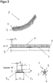
- Fig. 2 shows in the upper view a cleaning element 3, which at the head 2 according to Fig. 1 is attached.
- the cleaning element 3 is formed strand-like.
- the middle view of the Fig. 2 shows that the cleaning element 3 has a base strip 7, from which the pins 4 protrude.
- the pin 4 protrude from the surface 8 of the base strip 7 is substantially orthogonal.
- Each two outer lateral surfaces of the pins 4 are separated by a distance K.
- the distance K may be so small that the pins 4 abut each other. Ideally, the distance K is chosen so that even larger dirt particles between the pin 4 can get caught. A distance K of 1 mm to 10 mm is conceivable.
- the pins 4 are connected by a Tuftthetic with the base strip 7.
- Fig. 2 In the lower left view of the Fig. 2 is a plan view of the transverse side of the base strip 7 according to the middle view of Fig. 2 shown. Two rows of pins 4 are separated by a distance L.
- the distance L may be identical to the distance K.
- a pin 4 has a certain diameter, preferably 4 to 8 mm. Furthermore, the pins 4 have a Abrageus M of 0.5 to 2.5 cm.
- a sectional view of a cleaning element 3 is shown in the lower right view of the Fig. 2 .
- the pins 4 protrude in several directions from a base strip 7, whose longitudinal sides 7a, 7b are interconnected.
- the base strip 7 forms a tube, from whose outer surface 8 the pins 4 protrude in a star shape.
- the longitudinal sides 7a, 7b, which in the lower left view of Fig. 2 are shown sewn together.
- the number of directions in which project the pin 4 lies in the range of two to ten. Ideally, six to eight rows of pins 4 protrude in six to eight directions. Depending on the diameter of the pin 4 also significantly more directions can be realized.
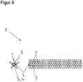
- Fig. 3 shows in the left view a sectional view of a cleaning element 3, which in Fig. 3 is shown in perspective in the right view. Also Fig. 3 shows that the base strip 7 is joined at its longitudinal sides 7a, 7b to form a tubular structure. From the outer surface 8 of the tubular structure, the pins 4 protrude.
- the pins 4 are made of microfibers.
- the microfibers are preferably made of polyester.
- Fig. 4 shows a cleaning device 1 '(not part of the invention), comprising a head 2, on which cleaning elements 3' are arranged, wherein the cleaning elements 3 'hanging strand-like from the head 2.
- the cleaning elements 3 ' have projecting pins 4.
- the cleaning elements 3 ' are designed as flat, flat structures, of which protrude the pin 4.
- Fig. 4 shows in a perspective view of the cleaning device 1 ', comprising a head 2 on which cleaning elements 3' are arranged, wherein the cleaning elements 3 'chenille material.
- the cleaning elements 3 ' have projecting pins 4, which have chenille material.
- the pins 4 are made of chenille material.
- the cleaning device 1 ' is designed as a mop.
- the head 2 has a receptacle 5 for a stem 6.
- At the head 2 of the stem 6 is arranged so that the cleaning device 1 'as a mop, namely as a mop, is configured.
- the cleaning elements 3 are made of base strips 7, from which the pins 4 protrude.
- the cleaning elements 3 hang strand-like from the head 2 as isolated elements down.
- the longitudinal sides of the base strips 7 are not sewn together.
- Fig. 5 shows in the upper view a cleaning element 3 '(not part of the invention), which at the head 2 according to Fig. 4 is attached.
- the cleaning element 3 ' is formed strand-like.
- the middle view of the Fig. 5 shows that the cleaning element 3 'has a base strip 7, from which the pins 4 protrude.
- the pin 4 protrude from the surface 8 of the base strip 7 is substantially orthogonal.
- Each two outer lateral surfaces of the pins 4 are separated by a distance K.
- the distance K may be so small that the pins 4 abut each other. Ideally, the distance K is chosen so that even larger dirt particles between the pin 4 can get caught. A distance K of 1 mm to 10 mm is conceivable.
- the pins 4 are connected by a Tuftthetic with the base strip 7.
- Fig. 5 In the lower view of the Fig. 5 is a plan view of the transverse side of the base strip 7 according to the middle view of Fig. 5 shown. Two rows of pins 4 are separated by a distance L.
- the distance L may be identical to the distance K.
- a pin 4 has a certain diameter, preferably 4 to 8 mm. Furthermore, the pins have a Abrageus M of 0.5 to 2.5 cm.
Landscapes
- Cleaning Implements For Floors, Carpets, Furniture, Walls, And The Like (AREA)
Description
- Die Erfindung betrifft ein Reinigungsgerät gemäß dem Oberbegriff des Patentanspruchs 1.
- Die
EP 2 347 691 A1 zeigt ein solches Reinigungsgerät. Aus derES 1 071 705 U - Bei dem gattungsbildenden Mopp ist nachteilig, dass eine bedienende Person besondere Sorgfalt walten lassen muss, um eine zu reinigende Fläche hinreichend gut zu reinigen. Die lose herabhängenden Schlaufen stellen nur eine relativ geringe Oberfläche zur Verfügung, welche mit einer zu reinigenden Fläche in Kontakt treten kann.
- Überdies kann nur der obere Bereich einer Schlaufe, welcher dem Kopf zugewandt ist, mit einem zufriedenstellenden Anpressdruck gegen eine zu reinigende Fläche gedrückt werden. Die Schlaufenenden, welche dem Kopf abgewandt sind, liegen auch bei hohem Anpressdruck des Kopfs gegen die zu reinigende Fläche nur leicht und lose auf der zu reinigenden Fläche auf.
- Der Erfindung liegt daher die Aufgabe zugrunde, ein Reinigungsgerät der eingangs genannten Art derart auszugestalten und weiterzubilden, dass die Reinigungselemente eine gute Reinigungswirkung auf einer zu reinigenden Fläche entfalten können.
- Die vorliegende Erfindung löst die zuvor genannte Aufgabe durch die Merkmale des Patentanspruchs 1.
- Erfindungsgemäß ist erkannt worden, dass abragende Zapfen in einer sehr großen Zahl an den strangartigen Reinigungselementen angeordnet werden können. Hierdurch kann die effektiv zur Reinigung zur Verfügung stehende Oberfläche des Materials, aus dem die Zapfen bestehen, deutlich erhöht werden. Weiter ist in erfinderischer Weise erkannt worden, dass Zapfen stets ein freies Ende aufweisen, welches der zur reinigenden Fläche zugewandt ist. Durch die freien Enden der Zapfen wird eine Art Rubbel-Effekt erzeugt, der auch hartnäckigen Schmutz von einer zu reinigenden Fläche entfernen kann. Mit nur geringem Anpressdruck kann die bedienende Person den Kopf über die zu reinigende Fläche führen und dabei problemlos Schmutzpartikel und Fluid durch die Zapfen aufnehmen.
- Vor diesem Hintergrund ragen die Zapfen eines Reinigungselements in mehreren Richtungen von diesem ab. Hierdurch ist sichergestellt, dass die bedienende Person den Kopf nahezu immer in der gleichen Position über die zu reinigende Fläche führen kann, wobei stets mehrere Zapfen mit der zu reinigenden Fläche in Kontakt kommen. Vorzugsweise ragen die Zapfen von einem Reinigungselement sternförmig ab.
- Vor diesem Hintergrund könnten die Reinigungselemente aus Basisstreifen gefertigt sein, von denen die Zapfen abragen. Die Basisstreifen können aus Geweben, Gewirken oder einem Vliesstoff gefertigt sind. Diese textilen Flächengebilde können aus Baumwolle, Viskose, Polyester, Polypropylen und/ oder Polyamid oder Mischungen hieraus gefertigt sein. Basisstreifen stellen eine relativ große ebene Fläche bereit, auf denen die Zapfen angeordnet werden können.
- Die Zapfen könnten durch eine Tuftverbindung mit den Basisstreifen verbunden sein. Eine Tuftverbindung legt die Zapfen dauerhaft und ohne Klebstoff auf den Basisstreifen fest, sodass diese auch im nassen Zustand stabil an den Basisstreifen fixiert sind.
- Die Längsseiten eines Basisstreifens könnten miteinander verbunden sein. Durch diese konkrete Ausgestaltung werden Zapfen, die im Wesentlichen orthogonal von den Basisstreifen abragen, derart ausgerichtet, dass sie in Sternform von einem in eine Röhrenform gezwungenen Basistreifen abragen. Hierdurch wird die Reinigungsleistung eines Reinigungselements erheblich erhöht. Vor diesem Hintergrund ist denkbar, dass die Längsseiten miteinander verklebt, vernäht, verschweißt, insbesondere ultraschallverschweißt, sind.
- Die Zapfen könnten eine Abragelänge von 0,5 bis 4,5 cm, bevorzugt 0,5 bis 2,5 cm, aufweisen. Unter Abragelänge wird die Weite verstanden, mit der ein Zapfen von der Oberfläche eines Basisstreifens abragt. Die Abragelänge gibt insoweit die Entfernung des freien Endes eines Zapfens von der Oberfläche des Basisstreifens an. Der Bereich von 0,5 bis 4,5 cm ist in fertigungstechnischer Hinsicht unproblematisch.
- Es hat sich herausgestellt, dass eine Abragelänge im Bereich 0,5 bis 2,5 cm die Zapfen ausreichend steif ausgestaltet, um eine gute Reinigungswirkung zu entfalten. Des Weiteren ist durch den Längenbereich sichergestellt, dass die Zapfen eine ausreichend große Oberfläche zur Aufnahme von Partikeln und Fluid zur Verfügung stellen können.
- Vor diesem Hintergrund könnten die Zapfen Mikrofasern aufweisen. Chenille-Material aus Mikrofasern zeichnet sich dadurch aus, dass es nicht nur unpolare Stoffe wie Fett, sondern auch polare Fluide durch Kapillarwirkung aufnehmen kann. Die Mikrofasern können Polyester, Polyamid, Viskose oder auch PLA (Polymilchsäure) aufweisen oder aus diesen Stoffen bestehen.
- Die Zapfen könnten Bikomponentenfasern aufweisen. Durch die Verwendung von Bikomponentenfasern können die Zapfen verschiedene Materialien aufweisen, die in feinere Fasern aufgesplittet sein können. Hierdurch wird ein Kapillareffekt noch gesteigert. Bevorzugt werden Bikomponentenfasern aus Polyamid und Polyester eingesetzt.
- Die Reinigungselemente und/ oder die Zapfen könnten Chenille-Material aufweisen. Chenille-Material kann eine große Oberfläche zur Verfügung stellen, um Partikel oder Schmutz aufzunehmen. Chenille-Material zeigt eine hohe Fluidabsorption. Aufgrund einer stark ausgebildeten Kapillarwirkung kann Chenille-Material besonders gut Fluide absorbieren. Die Zapfen sind bevorzugt aus Chenille-Material gefertigt.
- Chenille-Material wird hergestellt, indem Längsfäden mit Querfäden durchsetzt werden, wobei jeweils zwei Längsfäden miteinander verdrillt werden. Hierdurch ragen querveriaufende Mikrofasern mit ihren Spitzen sternförmig von den verdrillten Längsfäden ab und stellen eine hohe Oberfläche zur Verfügung. Dies ist in den
Figuren 2 und3 des spanischen GebrauchsmustersES 1 071 705 U - Der Kopf könnte eine Aufnahme für einen Stiel aufweisen. Obgleich das Reinigungsgerät auch als Handbürste ausgestaltet sein kann, ist bevorzugt, das Reinigungsgerät als Mopp, nämlich als Wischmopp, auszugestalten. Um dies zu realisieren, kann ein Stiel in ein Schraubgewinde in der Aufnahme eingeführt werden. Des Weiteren ist denkbar, dass der Stiel in die Aufnahme eingerastet oder eingeklipst wird.
- Vor diesem Hintergrund könnte am Kopf ein Stiel angeordnet sein, wobei das Reinigungsgerät als Mopp, nämlich als Wischmopp ausgestaltet ist.
- Am Kopf könnten ein oder mehrere Reinigungselemente angeordnet sein, welche in Schleifen gelegt ist bzw. sind. Hierbei ist vorteilhaft, dass die freien Enden der Reinigungselemente nahezu nicht ausfransen. Weiter ist vorteilhaft, dass keine Endkanten auftreten, die in separaten Schritten bearbeitet werden müssen.
- In der Zeichnung zeigen
- Fig. 1
- eine perspektivische Ansicht eines Reinigungsgeräts, welches als Mopp, nämlich als Wischmopp, ausgestaltet ist,
- Fig. 2
- in der oberen Ansicht ein einzelnes Reinigungselement, von welchem Zapfen abragen, in der mittleren Ansicht eine Ansicht auf die Längsseite eines Basisstreifens, von welchem Zapfen abragen, in der unteren linken Ansicht eine Draufsicht auf die Querseite des Basisstreifens und in der unteren rechten Ansicht eine Schnittansicht des Basisstreifens, dessen Längsseiten miteinander verbunden sind, wobei die Zapfen von diesem sternförmig abragen,
- Fig. 3
- in der linken Ansicht eine Schnittdarstellung des Basisstreifens, dessen Längsseiten miteinander verbunden sind, und in der rechten Ansicht eine perspektivische Ansicht auf die Längsseite des Basisstreifens, dessen Längsseiten miteinander verbunden sind,
- Fig. 4
- eine perspektivische Ansicht eines Reinigungsgerät (nicht Teil der Erfindung), welches als Mopp, nämlich als Wischmopp, ausgestaltet ist, wobei die Basisstreifen flach und an den Längsseiten unvernäht sind, und
- Fig. 5
- in der oberen Ansicht ein einzelnes Reinigungselements (nicht Teil der Erfindung), von welchem Zapfen abragen, in der mittleren Ansicht eine Ansicht auf die Längsseite eines Basisstreifens, von welchem Zapfen abragen, und in der unteren Ansicht eine Draufsicht auf die Querseite des Basisstreifens.
-
Fig. 1 zeigt ein Reinigungsgerät 1, umfassend einen Kopf 2, an welchem Reinigungselemente 3 angeordnet sind, wobei die Reinigungselemente 3 strangartig vom Kopf 2 herabhängen. Die Reinigungselemente 3 weisen abragende Zapfen 4 auf. -
Fig. 1 zeigt in einer perspektivischen Ansicht das Reinigungsgerät 1, umfassend einen Kopf 2 an welchem Reinigungselemente 3 angeordnet sind, wobei die Reinigungselemente 3 Chenille-Material aufweisen. Die Reinigungselemente 3 weisen abragende Zapfen 4 auf, die Chenille-Material aufweisen. Konkret sind die Zapfen 4 aus Chenille-Material gefertigt. - Das Reinigungsgerät gemäß
Fig. 1 ist als Mopp ausgestaltet. Der Kopf 2 weist eine Aufnahme 5 für einen Stiel 6 auf. Am Kopf 2 ist der Stiel 6 angeordnet, sodass das Reinigungsgerät 1 als Mopp, nämlich als Wischmopp ausgestaltet ist. - Die Zapfen 4 eines Reinigungselements 3 ragen in mehreren Richtungen von diesem ab. Die Reinigungselemente 3 sind aus Basisstreifen 7 gefertigt, von denen die Zapfen 4 abragen. Die Reinigungselemente 3 hängen strangartig als vereinzelte Elemente vom Kopf 2 herab.
-
Fig. 2 zeigt in der oberen Ansicht ein Reinigungselement 3, welches am Kopf 2 gemäßFig. 1 befestigt ist. Das Reinigungselement 3 ist strangartig ausgebildet. - Die mittlere Ansicht der
Fig. 2 zeigt, dass das Reinigungselement 3 einen Basisstreifen 7 aufweist, von welchem die Zapfen 4 abragen. In der mittleren Ansicht derFig. 2 ist konkret dargestellt, dass die Zapfen 4 von der Oberfläche 8 des Basisstreifens 7 im Wesentlichen orthogonal abragen. - Je zwei äußere Mantelflächen der Zapfen 4 sind durch einen Abstand K voneinander getrennt. Der Abstand K kann so gering sein, dass die Zapfen 4 aneinander anliegen. Idealerweise ist der Abstand K so gewählt, dass sich auch größere Schmutzpartikel zwischen den Zapfen 4 verfangen können. Denkbar ist ein Abstand K von 1 mm bis 10 mm. Die Zapfen 4 sind durch eine Tuftverbindung mit dem Basisstreifen 7 verbunden.
- In der unteren linken Ansicht der
Fig. 2 ist eine Draufsicht auf die Querseite des Basisstreifens 7 gemäß der mittleren Ansicht derFig. 2 dargestellt. Zwei Reihen von Zapfen 4 sind durch einen Abstand L voneinander getrennt. Der Abstand L kann mit dem Abstand K identisch sein. - Ein Zapfen 4 weist einen bestimmten Durchmesser, vorzugsweise 4 bis 8 mm, auf. Des Weiteren weisen die Zapfen 4 eine Abragelänge M von 0,5 bis 2,5 cm auf.
- In der rechten unteren Ansicht der
Fig. 2 ist eine Schnittansicht eines Reinigungselements 3 dargestellt. Die Zapfen 4 ragen in mehreren Richtungen von einem Basisstreifen 7 ab, dessen Längsseiten 7a, 7b miteinander verbunden sind. Der Basisstreifen 7 bildet eine Röhre, von deren äußerer Oberfläche 8 die Zapfen 4 sternförmig abragen. Vorzugsweise sind die Längsseiten 7a, 7b, welche in der linken unteren Ansicht derFig. 2 dargestellt sind, miteinander vernäht. - Die Anzahl der Richtungen, in denen die Zapfen 4 abragen, liegt im Bereich zwei bis zehn. Idealerweise ragen sechs bis acht Reihen der Zapfen 4 in sechs bis acht Richtungen ab. In Abhängigkeit vom Durchmesser der Zapfen 4 können auch deutlich mehr Richtungen realisiert werden.
-
Fig. 3 zeigt in der linken Ansicht eine Schnittdarstellung eines Reinigungselements 3, welches inFig. 3 in der rechten Ansicht perspektivisch dargestellt ist. AuchFig. 3 zeigt, dass der Basisstreifen 7 an seinen Längsseiten 7a, 7b zu einem röhrenförmigen Gebilde gefügt ist. Von der äußeren Oberfläche 8 des röhrenförmigen Gebildes ragen die Zapfen 4 ab. - Die Zapfen 4 bestehen aus Mikrofasern. Die Mikrofasern sind vorzugsweise aus Polyester gefertigt.
-
Fig. 4 zeigt ein Reinigungsgerät 1'(nicht Teil der Erfindung), umfassend einen Kopf 2, an welchem Reinigungselemente 3' angeordnet sind, wobei die Reinigungselemente 3' strangartig vom Kopf 2 herabhängen. Die Reinigungselemente 3'weisen abragende Zapfen 4 auf. Die Reinigungselemente 3' sind als flache, flächige Gebilde ausgestaltet, von denen die Zapfen 4 abragen. -
Fig. 4 zeigt in einer perspektivischen Ansicht das Reinigungsgerät 1', umfassend einen Kopf 2 an welchem Reinigungselemente 3' angeordnet sind, wobei die Reinigungselemente 3' Chenille-Material aufweisen. Die Reinigungselemente 3' weisen abragende Zapfen 4 auf, die Chenille-Material aufweisen. Konkret sind die Zapfen 4 aus Chenille-Material gefertigt. - Das Reinigungsgerät 1' gemäß
Fig. 4 ist als Mopp ausgestaltet. Der Kopf 2 weist eine Aufnahme 5 für einen Stiel 6 auf. Am Kopf 2 ist der Stiel 6 angeordnet, sodass das Reinigungsgerät 1' als Mopp, nämlich als Wischmopp, ausgestaltet ist. Die Zapfen 4 eines Reinigungselements 3' ragen in mehreren Richtungen von diesem ab. - Die Reinigungselemente 3' sind aus Basisstreifen 7 gefertigt, von denen die Zapfen 4 abragen. Die Reinigungselemente 3' hängen strangartig vom Kopf 2 als vereinzelte Elemente herab. Die Längsseiten der Basistreifen 7 sind nicht miteinander vernäht.
-
Fig. 5 zeigt in der oberen Ansicht ein Reinigungselement 3' (nicht Teil der Erfindung), welches am Kopf 2 gemäßFig. 4 befestigt ist. Das Reinigungselement 3' ist strangartig ausgebildet. Die mittlere Ansicht derFig. 5 zeigt, dass das Reinigungselement 3' einen Basisstreifen 7 aufweist, von welchem die Zapfen 4 abragen. In der mittleren Ansicht derFig. 5 ist konkret dargestellt, dass die Zapfen 4 von der Oberfläche 8 des Basisstreifens 7 im Wesentlichen orthogonal abragen. - Je zwei äußere Mantelflächen der Zapfen 4 sind durch einen Abstand K voneinander getrennt. Der Abstand K kann so gering sein, dass die Zapfen 4 aneinander anliegen. Idealerweise ist der Abstand K so gewählt, dass sich auch größere Schmutzpartikel zwischen den Zapfen 4 verfangen können. Denkbar ist ein Abstand K von 1 mm bis 10 mm. Die Zapfen 4 sind durch eine Tuftverbindung mit dem Basisstreifen 7 verbunden.
- In der unteren Ansicht der
Fig. 5 ist eine Draufsicht auf die Querseite des Basisstreifens 7 gemäß der mittleren Ansicht derFig. 5 dargestellt. Zwei Reihen von Zapfen 4 sind durch einen Abstand L voneinander getrennt. Der Abstand L kann mit dem Abstand K identisch sein. - Ein Zapfen 4 weist einen bestimmten Durchmesser, vorzugsweise 4 bis 8 mm, auf. Des Weiteren weisen die Zapfen eine Abragelänge M von 0,5 bis 2,5 cm auf.
Claims (10)
- Reinigungsgerät (1, 1'), umfassend einen Kopf (2), an welchem Reinigungselemente (3) angeordnet sind, wobei die Reinigungselemente (3) strangartig vom Kopf (2) herabhängen und wobei die Reinigungselemente (3) abragende Zapfen (4) aufweisen, dadurch gekennzeichnet, dass die Zapfen (4) eines Reinigungselements (3) in mehreren Richtungen von diesem abragen.
- Reinigungsgerät nach Anspruch 1, dadurch gekennzeichnet, dass die Reinigungselemente (3) aus Basisstreifen (7) gefertigt sind, von denen die Zapfen (4) abragen.
- Reinigungsgerät nach Anspruch 2, dadurch gekennzeichnet, dass die Zapfen (4) durch eine Tuftverbindung mit den Basisstreifen (7) verbunden sind.
- Reinigungsgerät nach Anspruch 2 oder 3, dadurch gekennzeichnet, dass die Längsseiten (7a, 7b) eines Basisstreifens (7) miteinander verbunden sind.
- Reinigungsgerät nach einem der voranstehenden Ansprüche, dadurch gekennzeichnet, dass die Zapfen (4) eine Abragelänge (M) von 0,5 bis 4,5 cm, bevorzugt 0,5 bis 2,5 cm, aufweisen.
- Reinigungsgerät nach einem der voranstehenden Ansprüche, dadurch gekennzeichnet, dass die Zapfen (4) Mikrofasern aufweisen.
- Reinigungsgerät nach einem der voranstehenden Ansprüche, dadurch gekennzeichnet, dass die Zapfen (4) Bikomponentenfasern aufweisen.
- Reinigungsgerät nach einem der voranstehenden Ansprüche, dadurch gekennzeichnet, dass die Reinigungselemente (3) und/ oder die Zapfen (4) Chenille-Material aufweisen
- Reinigungsgerät nach einem der voranstehenden Ansprüche, dadurch gekennzeichnet, dass der Kopf (2) eine Aufnahme (5) für einen Stiel (6) aufweist.
- Reinigungsgerät nach einem der voranstehenden Ansprüche, dadurch gekennzeichnet, dass am Kopf (2) ein oder mehrere Reinigungselemente (3) angeordnet ist bzw. sind, welche in Schleifen gelegt ist bzw. sind.
Priority Applications (1)
| Application Number | Priority Date | Filing Date | Title |
|---|---|---|---|
| PL12809577T PL2809217T3 (pl) | 2012-02-02 | 2012-11-15 | Mop z wiszącymi pasmowo elementami czyszczącymi |
Applications Claiming Priority (2)
| Application Number | Priority Date | Filing Date | Title |
|---|---|---|---|
| DE102012001932A DE102012001932A1 (de) | 2012-02-02 | 2012-02-02 | Mopp mit strangartig herabhängenden Reinigungselementen |
| PCT/EP2012/004743 WO2013113343A1 (de) | 2012-02-02 | 2012-11-15 | Mopp mit strangartig herabhängenden reinigungselementen |
Publications (2)
| Publication Number | Publication Date |
|---|---|
| EP2809217A1 EP2809217A1 (de) | 2014-12-10 |
| EP2809217B1 true EP2809217B1 (de) | 2017-02-08 |
Family
ID=47501038
Family Applications (1)
| Application Number | Title | Priority Date | Filing Date |
|---|---|---|---|
| EP12809577.5A Active EP2809217B1 (de) | 2012-02-02 | 2012-11-15 | Mopp mit strangartig herabhängenden reinigungselementen |
Country Status (6)
| Country | Link |
|---|---|
| EP (1) | EP2809217B1 (de) |
| CN (1) | CN104321002A (de) |
| DE (1) | DE102012001932A1 (de) |
| ES (1) | ES2623947T3 (de) |
| PL (1) | PL2809217T3 (de) |
| WO (1) | WO2013113343A1 (de) |
Cited By (1)
| Publication number | Priority date | Publication date | Assignee | Title |
|---|---|---|---|---|
| RU2787491C1 (ru) * | 2019-10-14 | 2023-01-09 | Карл Фройденберг Кг | Чистящий элемент |
Families Citing this family (2)
| Publication number | Priority date | Publication date | Assignee | Title |
|---|---|---|---|---|
| CN103860115A (zh) * | 2014-03-07 | 2014-06-18 | 洛阳理工学院 | 一种拖把 |
| DE102017004809B3 (de) * | 2017-05-19 | 2018-09-13 | Carl Freudenberg Kg | Moppkopf und Mopp, der den Moppkopf umfasst |
Family Cites Families (12)
| Publication number | Priority date | Publication date | Assignee | Title |
|---|---|---|---|---|
| US4085476A (en) * | 1975-08-05 | 1978-04-25 | South Eastern Cordage Company | Mop constructions and method of making same |
| GB9121778D0 (en) * | 1991-10-14 | 1991-11-27 | Unilever Plc | Cleaning device |
| DE29701349U1 (de) * | 1997-01-28 | 1997-04-30 | Grabarits Dieter | Gerät zur Naßreinigung von Fußböden oder ähnlichen Flächen |
| AT3245U1 (de) * | 1999-03-18 | 1999-12-27 | Frieb Handels Gmbh & Co Kg | Einrichtung zum reinigen |
| DE102006011368A1 (de) * | 2006-03-09 | 2007-09-20 | Carl Freudenberg Kg | Moppkopf und Wischmopp mit einem solchen Moppkopf |
| US8397338B2 (en) * | 2006-11-22 | 2013-03-19 | Minh T. Dihn | Multi-purpose mop system and method of use |
| US20080168614A1 (en) * | 2007-01-11 | 2008-07-17 | Guohua Gong | Tufted mop |
| CN201104859Y (zh) * | 2007-09-30 | 2008-08-27 | 涂祥茂 | 组合式拖把 |
| CN201798667U (zh) * | 2009-10-26 | 2011-04-20 | 柳叶春 | 擦手巾 |
| ES1071705Y (es) | 2009-11-11 | 2011-01-26 | Garcia Rafael Sanchez | Fregona mejorada |
| IT1397532B1 (it) * | 2010-01-21 | 2013-01-16 | Maranghi | Dispositivo pulente comprendente un mop a fettucce con strisce rivestite con microfibra per la pulizia dei pavimenti. |
| ITBG20100007U1 (it) * | 2010-03-15 | 2011-09-16 | Schlingentex S R L | Articolo per le pulizie domestiche o industriali confezionato in tessuto del tipo a maglia |
-
2012
- 2012-02-02 DE DE102012001932A patent/DE102012001932A1/de not_active Withdrawn
- 2012-11-15 WO PCT/EP2012/004743 patent/WO2013113343A1/de active Application Filing
- 2012-11-15 ES ES12809577.5T patent/ES2623947T3/es active Active
- 2012-11-15 PL PL12809577T patent/PL2809217T3/pl unknown
- 2012-11-15 EP EP12809577.5A patent/EP2809217B1/de active Active
- 2012-11-15 CN CN201280068995.4A patent/CN104321002A/zh active Pending
Cited By (1)
| Publication number | Priority date | Publication date | Assignee | Title |
|---|---|---|---|---|
| RU2787491C1 (ru) * | 2019-10-14 | 2023-01-09 | Карл Фройденберг Кг | Чистящий элемент |
Also Published As
| Publication number | Publication date |
|---|---|
| PL2809217T3 (pl) | 2017-08-31 |
| CN104321002A (zh) | 2015-01-28 |
| DE102012001932A1 (de) | 2013-08-08 |
| EP2809217A1 (de) | 2014-12-10 |
| WO2013113343A1 (de) | 2013-08-08 |
| ES2623947T3 (es) | 2017-07-12 |
Similar Documents
| Publication | Publication Date | Title |
|---|---|---|
| DE3809279C1 (de) | ||
| DE60031415T2 (de) | Reinigungsgerät mit vorrichtungen zum befestigen eines tuches | |
| EP2648592B1 (de) | Mopp | |
| EP2822436A1 (de) | Reinigungsgerät aus schaumstoff mit abrasiver oberfläche | |
| EP0744149A2 (de) | Wischtuch | |
| DE202008018031U1 (de) | Mehrseitiges Reinigungsgerät | |
| EP1991103A1 (de) | Moppkopf und wischmopp mit einem solchen moppkopf | |
| EP2809217B1 (de) | Mopp mit strangartig herabhängenden reinigungselementen | |
| EP3624661B1 (de) | Moppkopf und mopp, der den moppkopf umfasst | |
| EP2988644B1 (de) | Wischbezug | |
| DE102013006194B4 (de) | Mopp und Verfahren zur Herstellung seiner Reinigungsstreifen | |
| DE102018106942B4 (de) | Wischtuch | |
| EP0846438B1 (de) | Feuchtbodenwischgerät | |
| EP2145035A2 (de) | Wischtuch und wischbezug | |
| EP0629374A1 (de) | Feuchtwischtuch | |
| EP4044892A1 (de) | Reinigungselement | |
| DE202011000185U1 (de) | Saugdüse | |
| DE3809279C2 (de) | ||
| WO2009018878A1 (de) | Wischmop | |
| DE102017115027A1 (de) | Reinigungstuch für eine Reinigungseinrichtung | |
| EP3222189B1 (de) | Moppbezug und mopphalter | |
| DE3903594A1 (de) | Geschirr-reinigungsgeraet | |
| DE102018126818A1 (de) | Moppbezug für die Verwendung auf einem Moppbezughalter sowie Verfahren zum Reinigen einer Oberfläche mit einem Moppbezug | |
| DE202018106149U1 (de) | Moppbezug für die Verwendung auf einem Moppbezughalter | |
| DE202007008510U1 (de) | Reinigungslappen und Reinigungsapparat |
Legal Events
| Date | Code | Title | Description |
|---|---|---|---|
| PUAI | Public reference made under article 153(3) epc to a published international application that has entered the european phase |
Free format text: ORIGINAL CODE: 0009012 |
|
| 17P | Request for examination filed |
Effective date: 20140618 |
|
| AK | Designated contracting states |
Kind code of ref document: A1 Designated state(s): AL AT BE BG CH CY CZ DE DK EE ES FI FR GB GR HR HU IE IS IT LI LT LU LV MC MK MT NL NO PL PT RO RS SE SI SK SM TR |
|
| AX | Request for extension of the european patent |
Extension state: BA ME |
|
| DAX | Request for extension of the european patent (deleted) | ||
| GRAP | Despatch of communication of intention to grant a patent |
Free format text: ORIGINAL CODE: EPIDOSNIGR1 |
|
| INTG | Intention to grant announced |
Effective date: 20160916 |
|
| GRAS | Grant fee paid |
Free format text: ORIGINAL CODE: EPIDOSNIGR3 |
|
| GRAA | (expected) grant |
Free format text: ORIGINAL CODE: 0009210 |
|
| AK | Designated contracting states |
Kind code of ref document: B1 Designated state(s): AL AT BE BG CH CY CZ DE DK EE ES FI FR GB GR HR HU IE IS IT LI LT LU LV MC MK MT NL NO PL PT RO RS SE SI SK SM TR |
|
| REG | Reference to a national code |
Ref country code: GB Ref legal event code: FG4D Free format text: NOT ENGLISH |
|
| REG | Reference to a national code |
Ref country code: CH Ref legal event code: EP Ref country code: AT Ref legal event code: REF Ref document number: 866507 Country of ref document: AT Kind code of ref document: T Effective date: 20170215 |
|
| REG | Reference to a national code |
Ref country code: IE Ref legal event code: FG4D Free format text: LANGUAGE OF EP DOCUMENT: GERMAN |
|
| REG | Reference to a national code |
Ref country code: DE Ref legal event code: R096 Ref document number: 502012009517 Country of ref document: DE |
|
| REG | Reference to a national code |
Ref country code: LT Ref legal event code: MG4D |
|
| REG | Reference to a national code |
Ref country code: NL Ref legal event code: MP Effective date: 20170208 |
|
| REG | Reference to a national code |
Ref country code: ES Ref legal event code: FG2A Ref document number: 2623947 Country of ref document: ES Kind code of ref document: T3 Effective date: 20170712 |
|
| PG25 | Lapsed in a contracting state [announced via postgrant information from national office to epo] |
Ref country code: HR Free format text: LAPSE BECAUSE OF FAILURE TO SUBMIT A TRANSLATION OF THE DESCRIPTION OR TO PAY THE FEE WITHIN THE PRESCRIBED TIME-LIMIT Effective date: 20170208 Ref country code: FI Free format text: LAPSE BECAUSE OF FAILURE TO SUBMIT A TRANSLATION OF THE DESCRIPTION OR TO PAY THE FEE WITHIN THE PRESCRIBED TIME-LIMIT Effective date: 20170208 Ref country code: LT Free format text: LAPSE BECAUSE OF FAILURE TO SUBMIT A TRANSLATION OF THE DESCRIPTION OR TO PAY THE FEE WITHIN THE PRESCRIBED TIME-LIMIT Effective date: 20170208 Ref country code: NO Free format text: LAPSE BECAUSE OF FAILURE TO SUBMIT A TRANSLATION OF THE DESCRIPTION OR TO PAY THE FEE WITHIN THE PRESCRIBED TIME-LIMIT Effective date: 20170508 Ref country code: GR Free format text: LAPSE BECAUSE OF FAILURE TO SUBMIT A TRANSLATION OF THE DESCRIPTION OR TO PAY THE FEE WITHIN THE PRESCRIBED TIME-LIMIT Effective date: 20170509 |
|
| PG25 | Lapsed in a contracting state [announced via postgrant information from national office to epo] |
Ref country code: PT Free format text: LAPSE BECAUSE OF FAILURE TO SUBMIT A TRANSLATION OF THE DESCRIPTION OR TO PAY THE FEE WITHIN THE PRESCRIBED TIME-LIMIT Effective date: 20170608 Ref country code: NL Free format text: LAPSE BECAUSE OF FAILURE TO SUBMIT A TRANSLATION OF THE DESCRIPTION OR TO PAY THE FEE WITHIN THE PRESCRIBED TIME-LIMIT Effective date: 20170208 Ref country code: LV Free format text: LAPSE BECAUSE OF FAILURE TO SUBMIT A TRANSLATION OF THE DESCRIPTION OR TO PAY THE FEE WITHIN THE PRESCRIBED TIME-LIMIT Effective date: 20170208 Ref country code: BG Free format text: LAPSE BECAUSE OF FAILURE TO SUBMIT A TRANSLATION OF THE DESCRIPTION OR TO PAY THE FEE WITHIN THE PRESCRIBED TIME-LIMIT Effective date: 20170508 Ref country code: SE Free format text: LAPSE BECAUSE OF FAILURE TO SUBMIT A TRANSLATION OF THE DESCRIPTION OR TO PAY THE FEE WITHIN THE PRESCRIBED TIME-LIMIT Effective date: 20170208 Ref country code: RS Free format text: LAPSE BECAUSE OF FAILURE TO SUBMIT A TRANSLATION OF THE DESCRIPTION OR TO PAY THE FEE WITHIN THE PRESCRIBED TIME-LIMIT Effective date: 20170208 |
|
| PG25 | Lapsed in a contracting state [announced via postgrant information from national office to epo] |
Ref country code: CZ Free format text: LAPSE BECAUSE OF FAILURE TO SUBMIT A TRANSLATION OF THE DESCRIPTION OR TO PAY THE FEE WITHIN THE PRESCRIBED TIME-LIMIT Effective date: 20170208 Ref country code: EE Free format text: LAPSE BECAUSE OF FAILURE TO SUBMIT A TRANSLATION OF THE DESCRIPTION OR TO PAY THE FEE WITHIN THE PRESCRIBED TIME-LIMIT Effective date: 20170208 Ref country code: SK Free format text: LAPSE BECAUSE OF FAILURE TO SUBMIT A TRANSLATION OF THE DESCRIPTION OR TO PAY THE FEE WITHIN THE PRESCRIBED TIME-LIMIT Effective date: 20170208 Ref country code: RO Free format text: LAPSE BECAUSE OF FAILURE TO SUBMIT A TRANSLATION OF THE DESCRIPTION OR TO PAY THE FEE WITHIN THE PRESCRIBED TIME-LIMIT Effective date: 20170208 |
|
| REG | Reference to a national code |
Ref country code: DE Ref legal event code: R097 Ref document number: 502012009517 Country of ref document: DE |
|
| REG | Reference to a national code |
Ref country code: FR Ref legal event code: PLFP Year of fee payment: 6 |
|
| PG25 | Lapsed in a contracting state [announced via postgrant information from national office to epo] |
Ref country code: DK Free format text: LAPSE BECAUSE OF FAILURE TO SUBMIT A TRANSLATION OF THE DESCRIPTION OR TO PAY THE FEE WITHIN THE PRESCRIBED TIME-LIMIT Effective date: 20170208 Ref country code: SM Free format text: LAPSE BECAUSE OF FAILURE TO SUBMIT A TRANSLATION OF THE DESCRIPTION OR TO PAY THE FEE WITHIN THE PRESCRIBED TIME-LIMIT Effective date: 20170208 |
|
| PLBE | No opposition filed within time limit |
Free format text: ORIGINAL CODE: 0009261 |
|
| STAA | Information on the status of an ep patent application or granted ep patent |
Free format text: STATUS: NO OPPOSITION FILED WITHIN TIME LIMIT |
|
| 26N | No opposition filed |
Effective date: 20171109 |
|
| PG25 | Lapsed in a contracting state [announced via postgrant information from national office to epo] |
Ref country code: SI Free format text: LAPSE BECAUSE OF FAILURE TO SUBMIT A TRANSLATION OF THE DESCRIPTION OR TO PAY THE FEE WITHIN THE PRESCRIBED TIME-LIMIT Effective date: 20170208 |
|
| PG25 | Lapsed in a contracting state [announced via postgrant information from national office to epo] |
Ref country code: MC Free format text: LAPSE BECAUSE OF FAILURE TO SUBMIT A TRANSLATION OF THE DESCRIPTION OR TO PAY THE FEE WITHIN THE PRESCRIBED TIME-LIMIT Effective date: 20170208 |
|
| PG25 | Lapsed in a contracting state [announced via postgrant information from national office to epo] |
Ref country code: LI Free format text: LAPSE BECAUSE OF NON-PAYMENT OF DUE FEES Effective date: 20171130 Ref country code: CH Free format text: LAPSE BECAUSE OF NON-PAYMENT OF DUE FEES Effective date: 20171130 |
|
| PG25 | Lapsed in a contracting state [announced via postgrant information from national office to epo] |
Ref country code: LU Free format text: LAPSE BECAUSE OF NON-PAYMENT OF DUE FEES Effective date: 20171115 |
|
| REG | Reference to a national code |
Ref country code: BE Ref legal event code: MM Effective date: 20171130 |
|
| REG | Reference to a national code |
Ref country code: IE Ref legal event code: MM4A |
|
| PG25 | Lapsed in a contracting state [announced via postgrant information from national office to epo] |
Ref country code: MT Free format text: LAPSE BECAUSE OF FAILURE TO SUBMIT A TRANSLATION OF THE DESCRIPTION OR TO PAY THE FEE WITHIN THE PRESCRIBED TIME-LIMIT Effective date: 20170208 |
|
| PG25 | Lapsed in a contracting state [announced via postgrant information from national office to epo] |
Ref country code: IE Free format text: LAPSE BECAUSE OF NON-PAYMENT OF DUE FEES Effective date: 20171115 |
|
| PG25 | Lapsed in a contracting state [announced via postgrant information from national office to epo] |
Ref country code: BE Free format text: LAPSE BECAUSE OF NON-PAYMENT OF DUE FEES Effective date: 20171130 |
|
| REG | Reference to a national code |
Ref country code: AT Ref legal event code: MM01 Ref document number: 866507 Country of ref document: AT Kind code of ref document: T Effective date: 20171115 |
|
| PG25 | Lapsed in a contracting state [announced via postgrant information from national office to epo] |
Ref country code: AT Free format text: LAPSE BECAUSE OF NON-PAYMENT OF DUE FEES Effective date: 20171115 |
|
| PG25 | Lapsed in a contracting state [announced via postgrant information from national office to epo] |
Ref country code: HU Free format text: LAPSE BECAUSE OF FAILURE TO SUBMIT A TRANSLATION OF THE DESCRIPTION OR TO PAY THE FEE WITHIN THE PRESCRIBED TIME-LIMIT; INVALID AB INITIO Effective date: 20121115 |
|
| PG25 | Lapsed in a contracting state [announced via postgrant information from national office to epo] |
Ref country code: CY Free format text: LAPSE BECAUSE OF FAILURE TO SUBMIT A TRANSLATION OF THE DESCRIPTION OR TO PAY THE FEE WITHIN THE PRESCRIBED TIME-LIMIT Effective date: 20170208 |
|
| PG25 | Lapsed in a contracting state [announced via postgrant information from national office to epo] |
Ref country code: MK Free format text: LAPSE BECAUSE OF FAILURE TO SUBMIT A TRANSLATION OF THE DESCRIPTION OR TO PAY THE FEE WITHIN THE PRESCRIBED TIME-LIMIT Effective date: 20170208 |
|
| PG25 | Lapsed in a contracting state [announced via postgrant information from national office to epo] |
Ref country code: AL Free format text: LAPSE BECAUSE OF FAILURE TO SUBMIT A TRANSLATION OF THE DESCRIPTION OR TO PAY THE FEE WITHIN THE PRESCRIBED TIME-LIMIT Effective date: 20170208 Ref country code: IS Free format text: LAPSE BECAUSE OF FAILURE TO SUBMIT A TRANSLATION OF THE DESCRIPTION OR TO PAY THE FEE WITHIN THE PRESCRIBED TIME-LIMIT Effective date: 20170608 |
|
| PGFP | Annual fee paid to national office [announced via postgrant information from national office to epo] |
Ref country code: GB Payment date: 20231123 Year of fee payment: 12 |
|
| PGFP | Annual fee paid to national office [announced via postgrant information from national office to epo] |
Ref country code: ES Payment date: 20231201 Year of fee payment: 12 |
|
| PGFP | Annual fee paid to national office [announced via postgrant information from national office to epo] |
Ref country code: TR Payment date: 20231109 Year of fee payment: 12 Ref country code: IT Payment date: 20231129 Year of fee payment: 12 Ref country code: FR Payment date: 20231127 Year of fee payment: 12 Ref country code: DE Payment date: 20231121 Year of fee payment: 12 |
|
| PGFP | Annual fee paid to national office [announced via postgrant information from national office to epo] |
Ref country code: PL Payment date: 20231024 Year of fee payment: 12 |