EP2808753A2 - Elektronische Vorrichtung - Google Patents
Elektronische Vorrichtung Download PDFInfo
- Publication number
- EP2808753A2 EP2808753A2 EP13191309.7A EP13191309A EP2808753A2 EP 2808753 A2 EP2808753 A2 EP 2808753A2 EP 13191309 A EP13191309 A EP 13191309A EP 2808753 A2 EP2808753 A2 EP 2808753A2
- Authority
- EP
- European Patent Office
- Prior art keywords
- display unit
- main unit
- state
- hinge
- keyboard
- Prior art date
- Legal status (The legal status is an assumption and is not a legal conclusion. Google has not performed a legal analysis and makes no representation as to the accuracy of the status listed.)
- Granted
Links
Images


Classifications
-
- G—PHYSICS
- G06—COMPUTING OR CALCULATING; COUNTING
- G06F—ELECTRIC DIGITAL DATA PROCESSING
- G06F1/00—Details not covered by groups G06F3/00 - G06F13/00 and G06F21/00
- G06F1/16—Constructional details or arrangements
- G06F1/1613—Constructional details or arrangements for portable computers
- G06F1/1633—Constructional details or arrangements of portable computers not specific to the type of enclosures covered by groups G06F1/1615 - G06F1/1626
- G06F1/1637—Details related to the display arrangement, including those related to the mounting of the display in the housing
-
- G—PHYSICS
- G06—COMPUTING OR CALCULATING; COUNTING
- G06F—ELECTRIC DIGITAL DATA PROCESSING
- G06F1/00—Details not covered by groups G06F3/00 - G06F13/00 and G06F21/00
- G06F1/16—Constructional details or arrangements
- G06F1/1613—Constructional details or arrangements for portable computers
- G06F1/1615—Constructional details or arrangements for portable computers with several enclosures having relative motions, each enclosure supporting at least one I/O or computing function
- G06F1/1624—Constructional details or arrangements for portable computers with several enclosures having relative motions, each enclosure supporting at least one I/O or computing function with sliding enclosures, e.g. sliding keyboard or display
-
- G—PHYSICS
- G06—COMPUTING OR CALCULATING; COUNTING
- G06F—ELECTRIC DIGITAL DATA PROCESSING
- G06F1/00—Details not covered by groups G06F3/00 - G06F13/00 and G06F21/00
- G06F1/16—Constructional details or arrangements
- G06F1/1613—Constructional details or arrangements for portable computers
- G06F1/1633—Constructional details or arrangements of portable computers not specific to the type of enclosures covered by groups G06F1/1615 - G06F1/1626
- G06F1/1662—Details related to the integrated keyboard
-
- G—PHYSICS
- G06—COMPUTING OR CALCULATING; COUNTING
- G06F—ELECTRIC DIGITAL DATA PROCESSING
- G06F1/00—Details not covered by groups G06F3/00 - G06F13/00 and G06F21/00
- G06F1/16—Constructional details or arrangements
- G06F1/1613—Constructional details or arrangements for portable computers
- G06F1/1633—Constructional details or arrangements of portable computers not specific to the type of enclosures covered by groups G06F1/1615 - G06F1/1626
- G06F1/1675—Miscellaneous details related to the relative movement between the different enclosures or enclosure parts
- G06F1/1681—Details related solely to hinges
-
- H—ELECTRICITY
- H05—ELECTRIC TECHNIQUES NOT OTHERWISE PROVIDED FOR
- H05K—PRINTED CIRCUITS; CASINGS OR CONSTRUCTIONAL DETAILS OF ELECTRIC APPARATUS; MANUFACTURE OF ASSEMBLAGES OF ELECTRICAL COMPONENTS
- H05K7/00—Constructional details common to different types of electric apparatus
- H05K7/14—Mounting supporting structure in casing or on frame or rack
- H05K7/16—Mounting supporting structure in casing or on frame or rack on hinges or pivots
Definitions
- the present disclosure relates to an electronic device.
- JP-A-2009-230244 describes an apparatus that slides and tilts up/down a display unit with respect to a main unit.
- This apparatus includes a main unit that has a keyboard on its upper face for inputting information, and a display unit that has on its upper face a display for displaying information.
- the apparatus slides and tilts up/down the display unit with respect to the main unit with a slide mechanism and a tilt up/down mechanism.
- the hinge and the main unit are rotatably coupled about a rotating central shaft, and the hinge and the display unit are also rotatably coupled about a rotating central shaft.
- the display unit is restricted to facing in a predetermined direction.
- two overlapping hinges are provided in order to define the direction that the display faces with respect to the main unit while the display unit is moving, this means that the movement of the display unit is severely restricted. Therefore, it has been difficult to configure so that the display unit can move in a desired manner with respect to the main unit.
- an electronic device including a flat main unit provided with a keyboard, a flat display unit having a display face, the flat display unit configured to movably slide between a first state that overlaps the main unit and a second state that is erect with respect to the main unit, and a hinge that is arranged so as to overlap the keyboard in the first state, and is configured to couple the main unit and the display unit together so that the display unit can move with respect to the main unit.
- the hinge includes a first hinge member that is rotatably configured about a first rotating central shaft with respect to the main unit and rotatably configured about a second rotating central shaft with respect to the display unit, and a second hinge member that is rotatably configured about a third rotating central shaft with respect to the main unit and rotatably configured about a fourth rotating central shaft with respect to the display unit.
- the hinge is configured so that the first rotating central shaft moves along a predetermined curve when the display unit moves between the first state and the second state with respect to the main unit.
- a cam groove may be formed by the predetermined curve on the main unit, and the first rotating central shaft may move along the cam groove.
- a lower edge of the display unit may move across an upper face of the main unit.
- a lower edge of the display unit may move so as to rise above an upper face of the main unit.
- An upper face of the keyboard may be slanted with respect to an upper face of the main unit.
- the hinge may be arranged so as to extend toward a center in a width direction of the keyboard.
- a pointing device may be provided at an area on a near side of the keyboard.
- the first and the second rotating central shafts may be arranged in parallel on the main unit.
- the display unit that is moving respect to the main unit can be moved in a desired manner.
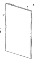
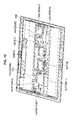
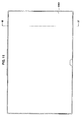
- FIGS. 1 to 3 are schematic diagrams illustrating the appearance of an information processing apparatus (electronic device) 1000.
- the information processing apparatus 1000 has a main unit 100 and a display unit 200.
- a keyboard 110 is provided on the main unit 100.
- the display unit 200 includes a touch panel 210 that is provided with a touch sensor on a display device such as a LCD.
- FIG. 1 illustrates a state in which the display unit 200 overlaps the display unit 200.
- the user can perform a desired operation by operating the touch panel 210.
- the user can use the information processing apparatus 1000 as a so-called tablet terminal.
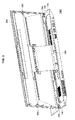
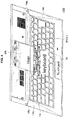
- FIG. 2 illustrates a state in which the display unit 200 has been slid up and is erect with respect to the main unit 100.
- the user can perform a desired operation by operating the keyboard 110.
- the user can also perform a desired operation by operating the touch panel 210 on the display unit 200.
- the user can also perform a desired operation by operating a touch pad 120, which is a pointing device provided on an area in front of the keyboard 110.
- FIG. 3 illustrates a state in which the state illustrated in FIG. 2 is viewed from a back face of the information processing apparatus 1000.
- the main unit 100 and the display unit 200 are connected via a hinge 300.
- the information processing apparatus 1000 can move between the state illustrated in FIG. 1 and the state illustrated in FIG. 2 by sliding the display unit 200 with respect to the main unit 100 via the hinge 300 (hereinafter also referred to as "surface-sliding").
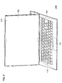
- FIG. 4 is a perspective diagram illustrating a state in which the display unit 200 has been removed from the state illustrated in FIG. 1 .
- a part of the near side of the hinge 300 overlaps the keyboard 110.
- the hinge 300 is provided extending toward a front side until it overlaps the keyboard 110 to ensure that the length of the hinge 300 in the front-rear direction is sufficiently long.
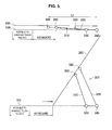
- FIG. 5 is a schematic diagram illustrating a link mechanism of the main unit 100, the display unit 200, and the hinge 300.
- the upper section of FIG. 5 schematically illustrates the state illustrated in FIG. 1
- the lower section schematically illustrates the state illustrated in FIG. 2 .
- a length L1 of the hinge 300 is long, so that the hinge 300 and the keyboard 110 overlap.
- the hinge 300 is configured from two hinge plates 310 and 320.
- the main unit 100 and the display unit 200 are connected via two links (joints) 330 and 340. Further, the main unit 100 and the display unit 200 are connected via two links (joints) 350 and 360. Based on such a configuration, when the display unit 200 is slid to the rear side of the main unit 100, the display unit 200 can be tilted with respect to the main unit 100.
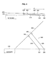
- FIG. 6 illustrates an example in which a length L2 of the display unit 200 is shorter than the length L1 of the display unit 200 in FIG. 5 , so that the hinge 300 does not overlap the keyboard 110.
- the display unit 200 when the display unit 200 is tilted, since the length L2 of the hinge is short, the tilt angle is smaller than in FIG. 5 , so the display unit 200 faces upward. Consequently, the keyboard 110 is arranged toward the front of the main unit 100, which means that the size of the keyboard 110 is limited.
- the tilt angle can be sufficient increased. Consequently, in the state illustrated in FIG. 2 , the lower edge of the display unit 200 can be positioned further toward the back of the main unit 100, so that the keyboard 110 can be arranged further toward the back of the main unit 100. This enables constituent elements, such as a touch pad, a palm rest, and a NFC device, to be arranged in an area in front of the keyboard 110. Further, by increasing the tilt angle, the visibility of the display unit 200 can be increased when the user places the information processing apparatus 1000 on a desk and operates it in the state illustrated in FIG. 2 .
- the usage area of the keyboard 110 can be increased without the position of the keyboard 110 being restricted by the position of the hinge 300. Consequently, the key pitch can also be increased.
- the usage area of the hinge 300 widens, so that the lower edge of the display unit 200 can be moved as far as the back of the main unit 100 when in the state illustrated in FIG. 2 . Consequently, the tilt angle can be increased and the area of the keyboard 110 can be further widened.
- this also enables the keyboard 110 to be arranged further to the rear of the main unit 100. Therefore, as illustrated in FIG.
- the touch pad 120 can be arranged on the front side of the keyboard 110, and a NFC device, a palm rest and the like can also be arranged.
- a NFC device, a palm rest and the like can also be arranged.
- the hinge 300 is configured so as to not overlap the keyboard 110, this means that the keyboard 110 is arranged further to the front of the main unit 100, which makes it difficult to ensure a space to provide the touch pad 120. Therefore, by configuring like in the present embodiment so that the hinge 300 overlaps the keyboard 110, a useful space can be ensured on the front side of the keyboard 110, so that a configuration having a greater added value can be obtained.
- the hinge 300 is arranged at only one location in the center of the main unit 100. If, for example, the hinge 300 is arranged at two locations at either end of the main unit 100, a space for the hinges 300 would probably be provided at either end of the keyboard 110, meaning that the horizontal width of the main unit 100 would likely increase. Moreover, this may also mean that a concave portion, a groove or the like to avoid the hinges is provided on the main unit 100 at either end of the keyboard 110. Therefore, by arranging the hinge 300 at just one location in the center of the main unit 100, the information processing apparatus 1000 can be made as compact as possible, and the configuration of the information processing apparatus 1000 can be made simple so as to not harm the appearance.
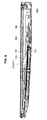
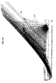
- FIG. 7 is a schematic diagram illustrating a cross-section along a front-rear direction of the center of the information processing apparatus 1000.
- an upper face 110a of the keyboard 110 is arranged at a predetermined angle with respect to an upper face 100a of the main unit 100.
- the upper face 100a of the main unit 100 and the upper face 110a of the keyboard 110 are not parallel. Consequently, as illustrated in FIG. 4 , a step between the upper face 110a of the keyboard 110 and the upper face 100a of the main unit 100 becomes greater and greater heading toward the back of the main unit 100.
- a predetermined space V is formed between the display unit 200 and the keyboard 110.
- the hinge 300 is arranged in this space V. Therefore, the hinge 300 can be housed in the space V without being interfered with by the keyboard 110 or the display unit 200.
- FIG. 8 is a cross-sectional view illustrating FIG. 7 in more detail. As illustrated in FIG. 8 , the hinge 300 is arranged in the space V between the keyboard 110 and the display unit 200.
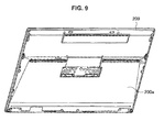
- FIG. 9 is a schematic diagram illustrating a convex-shaped area 200a provided on the rear side of the display unit 200. As illustrated in FIG. 9 , the bulge 200a is provided to the left and right of the center of the display unit 200. The bulge 200a is formed so that the thickness of the display unit 200 becomes thicker heading further back beyond the main unit 100 in the state illustrated in FIG. 1 to match the shape of the space V formed between the display unit 200 and the main unit 100.
- FIG. 10 is a schematic diagram illustrating an internal configuration of the display unit 200.
- a relay board 220 that combines three types of signal line into one from a touch panel board, a camera module, and a button board may be arranged on one convex-shaped area 200a.
- a board mounted with a WAN module and a SIM slot may be arranged on another convex-shaped area 200a.
- the convex-shaped area 200a can also be utilized without leaving any space by arranging an LCD harness, an antenna cable and the like on the convex-shaped area 200a.
- modules such as a speaker and a battery
- a speaker may also be arranged on the convex-shaped area 200a.
- a speaker is arranged on the convex-shaped area 200a, since a very large space can be used compared with the space on the main unit 100 side, a high audio quality speaker can be arranged. Compared with when arranged on the main unit 100, sound can be transmitted from a higher position, so that audio quality can be increased. Further, if a battery is arranged on the convex-shaped area 200a, the battery capacity can be increased.
- modules that are noise generation sources such as a motherboard, are arranged on the main unit 100. Consequently, it is desirable to arrange communication system modules, antennas and the like that are susceptible to the effects of noise on the convex-shaped area 200a of the display unit 200. This enables the effects of noise from the main unit 100 to be suppressed. If arranging an antenna, the antenna can also be effectively employed as a countermeasure against SAR. Further, a NFC (near field communication) device may also be mounted on the convex-shaped area 200a.
- NFC near field communication
- FIGS. 11 and 12 are schematic diagrams illustrating examples in which a module is arranged on the convex-shaped area 200a.
- FIG. 11 illustrates the state of FIG. 1 as viewed from above.
- FIG. 12 illustrates a cross-section along the dashed line III-III' in FIG. 11 , in which a cross-section further to the right side then the hinge 300 is shown.
- a WAN board 240 is arranged as a module on the convex-shaped area 200a on the right side of the display unit 200.
- Other modules can also be similarly arranged. Since the vertical width of the space V increases heading toward the back of the information processing apparatus 1000, it is preferred to arrange modules that are comparatively thick at the far side of the information processing apparatus 1000, and modules that are comparatively thin at the near side of the information processing apparatus 1000.
- the information processing apparatus 1000 can be made as small as possible by effectively utilizing this space by arranging modules on the convex-shaped area 200a. These modules can be arranged without increasing the overall thickness of the information processing apparatus 1000. By arranging modules that would normally be arranged on the main unit 100 on the display unit 200 side, wasted space can be eliminated, and the information processing apparatus 1000 can be made more compact and lighter.
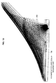
- FIG. 13 is a schematic diagram illustrating the display unit 200 tilted with respect to the main unit 100, which shows a state as viewed from the right side of the information processing apparatus 1000.
- FIG. 14 is a diagram illustrating the display unit 200 tilted with respect to the main unit 100, which shows the position of the display unit 200 shifted in the horizontal direction so as not to overlap the display unit 200.
- the display unit 200 when the display unit 200 is tilted from the state illustrated in FIG. 1 to the state illustrated in FIG. 2 , the display unit 200 moves across the upper face of the main unit 100. More specifically, the lower edge of the display unit 200 moves across the upper face of the main unit 100. Further, while between the state illustrated in FIG. 1 and the state illustrated in FIG. 2 , the lower edge of the display unit 200 moves so as to rise above the upper face of the main unit 100. Consequently, when tilting the display unit 200, since the display unit 200 follows a smooth track above the main unit 100, a graceful movement can be realized. Further, when moving from the state illustrated in FIG. 1 to the state illustrated in FIG. 2 , since the display unit 200 becomes parallel to the main unit 100 at a comparatively early stage, a graceful surface-slide can also be realized.
- FIG. 15 is a schematic diagram illustrating a link mechanism of the main unit 100, the display unit 200, and the hinge 300 for the purpose of realizing the movements illustrated in FIGS. 13 and 14 .
- the mechanism illustrated in FIG. 15 adds a link 370 to the mechanism of FIG. 5 .
- the link 370 By providing the link 370, the degree of freedom of the display unit 200 is decreased by one degree, so that a change in the tilt angle of the display unit 200 when the angle of the hinge 300 is fixed can be suppressed.
- a slider 380 is provided on the link 330, so that when the display unit 200 is tilted from the state illustrated in FIG. 1 to the state illustrated in FIG. 2 , the slider 380 moves along a predetermined curve. Specifically, the slider 380 is inserted into a curved cam 400, and moves along the curved cam 400.
- the trajectory that the display unit 200 follows during an open/close operation can be arbitrary set by arbitrarily setting the shape of the curved cam 400. Therefore, the above-described movement of the lower edge of the display unit 200 across the upper face of the main unit 100 can be realized by optimally setting the shape of the curved cam 400.
- the display unit 200 can be reliably prevented from interfering with the keyboard 110.
- this also enables fine adjustments to movement to be made, such that the lower edge of the display unit 200 moves in a convex shape above the upper face of the main unit 100 during the tilt process. Therefore, by configuring so that the slider 380 moves along a curve, a desired tilt operation of the display unit 200 can be realized.
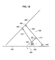
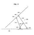
- FIGS. 16 and 17 illustrate cases in which the slider 380 moves linearly in a horizontal direction.
- the lower edge of the display unit 200 is at a lower position than the upper face of the main unit 100, so that the display unit 200 and the main unit 100 interfere with each other. Therefore, when the slider 380 is configured so as to move linearly in a horizontal direction, movement of the display unit 200 like that illustrated in FIGS. 13 and 14 is not be realized.
- the slider 380 since the slider 380 is configured so as to move along a curve, the movement of the display unit 200 can be provided with a degree of freedom, which enables a graceful movement to be realized in which the display unit 200 (display) smoothly tracks above the keyboard. Further, by configuring so that the slider 380 moves along a curve, interference with the keyboard 110 can be easily avoided, so that the degree of design freedom of the hinge 300 can also be increased.
- FIGS. 18 and 19 are schematic diagrams illustrating a detailed configuration of the hinge 300 and the curved cam 400.
- FIG. 18 is a schematic diagram illustrating movement of the display unit 200 with respect to the main unit 100, and the specific shape of the curved cam 400. Similar to FIG. 13 , the drawing on the left side of FIG. 18 illustrates only a part of the main unit 100. The drawing on the right side of FIG. 18 is an enlarged illustration of the curved cam 400 provided in the main unit 100.
- FIG. 19 is a schematic diagram illustrating a detailed configuration of the hinge 300, in which the top drawing illustrates the hinge 300 as viewed from above in a state in which the display unit 200 overlaps the main unit 100 ( FIG. 1 ) with the display unit 200 removed. Further, the bottom drawings in FIG. 19 illustrate cross-sections along the dashed lines I-I' and II-II' illustrated in the top drawing. As illustrated in FIG. 19 , the link 330 also carries out the function of the slider 380 illustrated in FIG. 5 , and can move along the curved cam 400. The link 330 extends from the position of the dashed line I-I' to the position of the dashed line II-II' in a direction orthogonal to each of the dashed lines.
- the link 370 is provided at a position on the dashed line I-I'.
- the display unit 200 is mounted on an attachment plate 230.
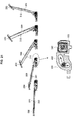
- FIG. 20 is a perspective diagram illustrating the configuration the hinge 300.
- the top drawing in FIG. 20 illustrates the hinge 300 as seen from above. Further, the bottom drawing in FIG. 20 illustrates the hinge 300 as seen from below (main unit side).
- an attachment member 130 is integrally fixed to the main unit 100.
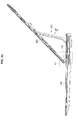
- FIG. 21 is a schematic diagram illustrating turning of the thus-configured hinge 300 about the main unit 100.
- the link 330 that also carries out the function of the slider 380 moves along the curved cam 400. Consequently, a graceful movement like that illustrated in FIG. 11 can be realized.
- a latch mechanism that engages the display unit 200 with the main unit 100 when the display unit 200 is closed as illustrated in FIG. 1 and open as illustrated in FIG. 2 will be described.
- a hook 140 is provided at either end on the left and right of the main unit 100.
- latches 260 for engaging with the hooks 140 are provided on the display unit 200.
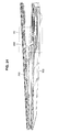
- FIG. 22 is a schematic diagram illustrating a right side face of the information processing apparatus 1000 in the state illustrated in FIG. 2 , which illustrates a cross-section along the front-rear direction at a position where a latch structure is provided.
- a hook 140 is provided on the main unit 100.
- the hook 140 engages with an engagement member 250 that is provided near a lower edge of the display unit 200.
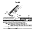
- FIG. 23 is an enlarged cross-sectional view of the area A1 illustrated in FIG. 22 .
- the shape of the curved cam 400 is set so that the position of the hook 140 and the engagement member 250 match. Therefore, when the display unit 200 has been tilted with respect to the main unit 100, the position of the hook 140 and the engagement member 250 will match, so that the portion 142 on a lower side of the hook 140 reliably abuts the abutment face 252 of the engagement member 250.
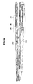
- FIG. 24 is a schematic diagram illustrating a state immediately before the main unit 100 and the display unit 200 overlap when moving from the state illustrated in FIG. 2 to the state illustrated in FIG. 1 .
- a latch 260 provided on the display unit 200 moves towards the hook 140.
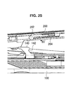
- FIG. 25 is an enlarged cross-sectional view of the area A2 in FIG. 24 .
- the latch 260 is configured from a slider 262 and a compression spring 264.
- the slider 262 is urged in the direction of the arrow B2 by the compression spring 264.
- a concave portion 142 that engages with the tip of the slider 262 is provided on the hook 140.
- FIG. 26 is a schematic diagram illustrating a state in which the main unit 100 and the display unit 200 are in a state closer than that in FIG. 24 when moving from the state illustrated in FIG. 2 to the state illustrated in FIG. 1 .
- FIG. 27 is an enlarged cross-sectional view of area A3 in FIG. 26 .
- the tip of the hook 140 abuts the slider 262, and the slider 262 moves in the direction of the arrow B3 in response to an urging force from the compression spring 264.
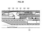
- FIG. 28 illustrates a state in which the main unit 100 and the display unit 200 are completely overlapping (state illustrated in FIG. 1 ). Further, FIG. 29 is an enlarged cross-sectional view of the area A4 in FIG. 28 .
- the slider 262 is urged in the direction of the arrow B2 by the compression spring 264, and the tip of the slider 262 engages the concave portion 142 of the hook 140. Due to the engagement of the tip of the slider 262 with the concave portion 142 of the hook 140, the display unit 200 is fixed to the main unit 100. In this state, the touch panel 210 of the display unit 200 faces upwards. Therefore, the user can use the information processing apparatus 1000 as a so-called tablet terminal.
- the display unit 200 When moving from the state illustrated in FIG. 1 to the state illustrated in FIG. 2 , the display unit 200 is lifted up with respect to the main unit 100 so that the information processing apparatus 1000 changes from the state illustrated in FIG. 28 to the state illustrated in FIG. 26 . Consequently, while following the shape of the concave portion 142, the slider 262 moves in the direction of the arrow B3 in response to an urging force from the compression spring 264. Therefore, the engagement between the hook 140 and the slider 262 is released, so that the display unit 200 can be surface-slid to the state illustrated in FIG. 2 .
- the hinge 300 overlaps the keyboard 110 when the display unit 200 is folded away, the obtained dedicated surface area of the keyboard 110 can be as large as possible, and a touch pad, a palm rest and the like can be arranged on the front face of the keyboard. Further, since the hinge 300 is configured so as to move along the curved cam 400, a desired movement for the hinge 300 can be realized, so that the lower edge of the display unit 200 can gracefully move across the upper face of the main unit 100.
- present technology may also be configured as below.
Landscapes
- Engineering & Computer Science (AREA)
- Theoretical Computer Science (AREA)
- Computer Hardware Design (AREA)
- Physics & Mathematics (AREA)
- General Physics & Mathematics (AREA)
- General Engineering & Computer Science (AREA)
- Human Computer Interaction (AREA)
- Mathematical Physics (AREA)
- Microelectronics & Electronic Packaging (AREA)
- Casings For Electric Apparatus (AREA)
- Telephone Set Structure (AREA)
- Devices For Indicating Variable Information By Combining Individual Elements (AREA)
- Pivots And Pivotal Connections (AREA)
Applications Claiming Priority (1)
| Application Number | Priority Date | Filing Date | Title |
|---|---|---|---|
| JP2013112336A JP6146138B2 (ja) | 2013-05-28 | 2013-05-28 | 電子機器 |
Publications (3)
| Publication Number | Publication Date |
|---|---|
| EP2808753A2 true EP2808753A2 (de) | 2014-12-03 |
| EP2808753A3 EP2808753A3 (de) | 2015-02-18 |
| EP2808753B1 EP2808753B1 (de) | 2018-09-05 |
Family
ID=49552186
Family Applications (1)
| Application Number | Title | Priority Date | Filing Date |
|---|---|---|---|
| EP13191309.7A Not-in-force EP2808753B1 (de) | 2013-05-28 | 2013-11-01 | Elektronische Vorrichtung |
Country Status (4)
| Country | Link |
|---|---|
| US (1) | US9229480B2 (de) |
| EP (1) | EP2808753B1 (de) |
| JP (1) | JP6146138B2 (de) |
| CN (2) | CN203982266U (de) |
Families Citing this family (7)
| Publication number | Priority date | Publication date | Assignee | Title |
|---|---|---|---|---|
| JP6146138B2 (ja) * | 2013-05-28 | 2017-06-14 | ソニー株式会社 | 電子機器 |
| JP2014232387A (ja) * | 2013-05-28 | 2014-12-11 | ソニー株式会社 | 電子機器 |
| TWI476501B (zh) * | 2013-06-18 | 2015-03-11 | Sintai Optical Shenzhen Co Ltd | 影像擷取裝置及方法 |
| US9444980B2 (en) * | 2013-07-01 | 2016-09-13 | Canon Kabushiki Kaisha | Electronic apparatus and imaging apparatus |
| DE102016118597A1 (de) * | 2016-09-30 | 2018-04-05 | Ma Lighting Technology Gmbh | Lichtstellpult mit verstellbar gelagertem Bildschirmgehäuse |
| USD890166S1 (en) * | 2018-03-26 | 2020-07-14 | Hewlett-Packard Development Company, L.P. | Laptop computer |
| USD1095517S1 (en) * | 2024-01-24 | 2025-09-30 | Getac Technology Corporation | Laptop computer |
Citations (1)
| Publication number | Priority date | Publication date | Assignee | Title |
|---|---|---|---|---|
| JP2009230244A (ja) | 2008-03-19 | 2009-10-08 | Sony Corp | 携帯型情報処理装置 |
Family Cites Families (34)
| Publication number | Priority date | Publication date | Assignee | Title |
|---|---|---|---|---|
| EP0454120A3 (en) * | 1990-04-27 | 1992-12-30 | Kabushiki Kaisha Toshiba | Portable computer comprising keyboard and coordinate input tablet |
| US5200913A (en) * | 1990-05-04 | 1993-04-06 | Grid Systems, Inc. | Combination laptop and pad computer |
| JPH0619597A (ja) * | 1992-07-03 | 1994-01-28 | Hitachi Ltd | キーボード入力装置 |
| JPH0635565A (ja) * | 1992-07-13 | 1994-02-10 | Fujitsu Ltd | 携帯用情報機器 |
| JPH07182068A (ja) * | 1993-12-24 | 1995-07-21 | Toshiba Corp | 情報処理装置 |
| JPH10214034A (ja) * | 1997-01-29 | 1998-08-11 | Canon Inc | 卓上型表示装置 |
| US6288891B1 (en) * | 1996-11-21 | 2001-09-11 | Canon Kabushiki Kaisha | Movable display apparatus |
| US6464195B1 (en) * | 1997-12-04 | 2002-10-15 | Raymond Hildebrandt | Ergonomic mounting for computer screen displays |
| US6353529B1 (en) * | 1998-11-12 | 2002-03-05 | Thomas Cies | Z-configuration structure for computers, scanners, and communications and video devices |
| FI116345B (fi) * | 2000-12-19 | 2005-10-31 | Nokia Corp | Kannettavat elektroniset laitteet |
| JP4094937B2 (ja) * | 2001-11-19 | 2008-06-04 | 三星電子株式会社 | モニタ装置 |
| JP2003223238A (ja) * | 2002-01-28 | 2003-08-08 | Internatl Business Mach Corp <Ibm> | コンピュータ装置、モニタユニットおよび対面ユニットの支持構造物 |
| US6798649B1 (en) * | 2002-02-25 | 2004-09-28 | Think Outside, Inc. | Mobile computer with foldable keyboard |
| KR100512718B1 (ko) * | 2002-07-16 | 2005-09-07 | 삼성전자주식회사 | 모니터장치 |
| KR100482007B1 (ko) * | 2002-09-28 | 2005-04-13 | 삼성전자주식회사 | 모니터장치 |
| US6903927B2 (en) * | 2002-12-17 | 2005-06-07 | Nokia Corporation | Convertible mobile computing device |
| US6816365B2 (en) * | 2003-01-28 | 2004-11-09 | International Business Machines Corporation | Laptop display screen and keyboard mounting structure |
| TW595745U (en) * | 2003-02-19 | 2004-06-21 | Tatung Co | Assembling type personal computer |
| US6826043B2 (en) * | 2003-02-26 | 2004-11-30 | First International Computer Inc. | Connecting mechanism |
| US6961234B2 (en) | 2003-09-04 | 2005-11-01 | Kabushiki Kaisha Toshiba | Display support mechanism |
| KR100541737B1 (ko) * | 2003-10-09 | 2006-01-11 | 삼성전자주식회사 | 휴대용 컴퓨터 |
| KR100628119B1 (ko) * | 2004-08-17 | 2006-09-26 | 엘지전자 주식회사 | 평판형 모니터 |
| US7239505B2 (en) * | 2004-10-08 | 2007-07-03 | Microsoft Corporation | Direct hinge for optimizing conversion |
| US7184263B1 (en) * | 2005-08-04 | 2007-02-27 | Acer Inc. | Portable computer |
| TWI295705B (en) * | 2006-07-26 | 2008-04-11 | Compal Electronics Inc | Portable electronic apparatus with function of adjusting tilt angle of body and apparatus base thereof |
| TWM322011U (en) * | 2007-02-08 | 2007-11-11 | Chung-Yi Lee | Laptop computer supporting device |
| TW200844357A (en) * | 2007-05-08 | 2008-11-16 | Jarllytec Co Ltd | Supporting structure with adjustable elevation |
| US20090159767A1 (en) * | 2007-12-24 | 2009-06-25 | Wen-Sung Ko | Sliding bracket |
| JP5415199B2 (ja) * | 2009-09-28 | 2014-02-12 | パナソニック株式会社 | 電子装置 |
| JP5599226B2 (ja) * | 2010-05-17 | 2014-10-01 | 三菱製鋼株式会社 | 開閉装置 |
| JP5673096B2 (ja) | 2010-12-28 | 2015-02-18 | ソニー株式会社 | 機器開閉機構および情報機器 |
| TWI459886B (zh) * | 2011-03-11 | 2014-11-01 | Quanta Comp Inc | 攜帶式電子裝置 |
| WO2012134015A1 (ko) * | 2011-03-28 | 2012-10-04 | (주)쉘라인 | 슬라이딩 및 틸팅 가능한 태블릿 컴퓨터 |
| JP6146138B2 (ja) * | 2013-05-28 | 2017-06-14 | ソニー株式会社 | 電子機器 |
-
2013
- 2013-05-28 JP JP2013112336A patent/JP6146138B2/ja not_active Expired - Fee Related
- 2013-10-28 US US14/064,500 patent/US9229480B2/en not_active Expired - Fee Related
- 2013-11-01 EP EP13191309.7A patent/EP2808753B1/de not_active Not-in-force
-
2014
- 2014-05-23 CN CN201420265836.XU patent/CN203982266U/zh not_active Expired - Fee Related
- 2014-05-23 CN CN201410220547.2A patent/CN104216473B/zh not_active Expired - Fee Related
Patent Citations (1)
| Publication number | Priority date | Publication date | Assignee | Title |
|---|---|---|---|---|
| JP2009230244A (ja) | 2008-03-19 | 2009-10-08 | Sony Corp | 携帯型情報処理装置 |
Also Published As
| Publication number | Publication date |
|---|---|
| JP6146138B2 (ja) | 2017-06-14 |
| CN104216473B (zh) | 2019-04-30 |
| EP2808753A3 (de) | 2015-02-18 |
| US20140355187A1 (en) | 2014-12-04 |
| EP2808753B1 (de) | 2018-09-05 |
| CN203982266U (zh) | 2014-12-03 |
| US9229480B2 (en) | 2016-01-05 |
| CN104216473A (zh) | 2014-12-17 |
| JP2014232386A (ja) | 2014-12-11 |
Similar Documents
| Publication | Publication Date | Title |
|---|---|---|
| EP2808753B1 (de) | Elektronische Vorrichtung | |
| US8682404B2 (en) | Sliding module for sliding type portable communication device | |
| US8947871B2 (en) | Portable electronic device and slide rail device | |
| CN103123524B (zh) | 便携式计算机 | |
| US8964377B2 (en) | Electronic device having slide-tilt operation | |
| WO2013114820A1 (en) | Information terminal apparatus | |
| KR101101073B1 (ko) | 단말기 | |
| US20140375194A1 (en) | Information terminal apparatus | |
| US8446712B2 (en) | Portable electronic apparatus | |
| CN101189855B (zh) | 多功能电子装置 | |
| US9261928B2 (en) | Electronic device | |
| EP1760996A2 (de) | Schiebevorrichtung für ein tragbares Endgerät | |
| WO2021171017A1 (en) | A mobile terminal with sliding shells | |
| CN103081447B (zh) | 电子机器用滑动装置 | |
| JP6322908B2 (ja) | 表示装置および表示支持装置 | |
| EP2808754A1 (de) | Elektronische Vorrichtung | |
| JP5228919B2 (ja) | 携帯電子機器 | |
| CN102655534A (zh) | 阻尼装置及横向滑动型便携式终端 | |
| EP3644585A1 (de) | Haltevorrichtung | |
| US20130163158A1 (en) | Terminal apparatus | |
| JP2015127895A (ja) | 情報処理装置 | |
| WO2014119010A1 (ja) | 電子機器 | |
| KR20130092037A (ko) | 이동 단말기 | |
| KR20120091569A (ko) | 슬라이딩형 휴대용 단말기 | |
| CN105763276A (zh) | 调音控制台 |
Legal Events
| Date | Code | Title | Description |
|---|---|---|---|
| PUAI | Public reference made under article 153(3) epc to a published international application that has entered the european phase |
Free format text: ORIGINAL CODE: 0009012 |
|
| 17P | Request for examination filed |
Effective date: 20131101 |
|
| AK | Designated contracting states |
Kind code of ref document: A2 Designated state(s): AL AT BE BG CH CY CZ DE DK EE ES FI FR GB GR HR HU IE IS IT LI LT LU LV MC MK MT NL NO PL PT RO RS SE SI SK SM TR |
|
| AX | Request for extension of the european patent |
Extension state: BA ME |
|
| PUAL | Search report despatched |
Free format text: ORIGINAL CODE: 0009013 |
|
| AK | Designated contracting states |
Kind code of ref document: A3 Designated state(s): AL AT BE BG CH CY CZ DE DK EE ES FI FR GB GR HR HU IE IS IT LI LT LU LV MC MK MT NL NO PL PT RO RS SE SI SK SM TR |
|
| AX | Request for extension of the european patent |
Extension state: BA ME |
|
| RIC1 | Information provided on ipc code assigned before grant |
Ipc: G06F 1/16 20060101AFI20150112BHEP |
|
| GRAP | Despatch of communication of intention to grant a patent |
Free format text: ORIGINAL CODE: EPIDOSNIGR1 |
|
| STAA | Information on the status of an ep patent application or granted ep patent |
Free format text: STATUS: GRANT OF PATENT IS INTENDED |
|
| INTG | Intention to grant announced |
Effective date: 20180328 |
|
| GRAS | Grant fee paid |
Free format text: ORIGINAL CODE: EPIDOSNIGR3 |
|
| GRAA | (expected) grant |
Free format text: ORIGINAL CODE: 0009210 |
|
| STAA | Information on the status of an ep patent application or granted ep patent |
Free format text: STATUS: THE PATENT HAS BEEN GRANTED |
|
| AK | Designated contracting states |
Kind code of ref document: B1 Designated state(s): AL AT BE BG CH CY CZ DE DK EE ES FI FR GB GR HR HU IE IS IT LI LT LU LV MC MK MT NL NO PL PT RO RS SE SI SK SM TR |
|
| REG | Reference to a national code |
Ref country code: GB Ref legal event code: FG4D |
|
| REG | Reference to a national code |
Ref country code: CH Ref legal event code: EP |
|
| REG | Reference to a national code |
Ref country code: AT Ref legal event code: REF Ref document number: 1038571 Country of ref document: AT Kind code of ref document: T Effective date: 20180915 |
|
| REG | Reference to a national code |
Ref country code: IE Ref legal event code: FG4D |
|
| REG | Reference to a national code |
Ref country code: DE Ref legal event code: R096 Ref document number: 602013043047 Country of ref document: DE |
|
| REG | Reference to a national code |
Ref country code: NL Ref legal event code: MP Effective date: 20180905 |
|
| REG | Reference to a national code |
Ref country code: LT Ref legal event code: MG4D |
|
| PG25 | Lapsed in a contracting state [announced via postgrant information from national office to epo] |
Ref country code: GR Free format text: LAPSE BECAUSE OF FAILURE TO SUBMIT A TRANSLATION OF THE DESCRIPTION OR TO PAY THE FEE WITHIN THE PRESCRIBED TIME-LIMIT Effective date: 20181206 Ref country code: NO Free format text: LAPSE BECAUSE OF FAILURE TO SUBMIT A TRANSLATION OF THE DESCRIPTION OR TO PAY THE FEE WITHIN THE PRESCRIBED TIME-LIMIT Effective date: 20181205 Ref country code: LT Free format text: LAPSE BECAUSE OF FAILURE TO SUBMIT A TRANSLATION OF THE DESCRIPTION OR TO PAY THE FEE WITHIN THE PRESCRIBED TIME-LIMIT Effective date: 20180905 Ref country code: BG Free format text: LAPSE BECAUSE OF FAILURE TO SUBMIT A TRANSLATION OF THE DESCRIPTION OR TO PAY THE FEE WITHIN THE PRESCRIBED TIME-LIMIT Effective date: 20181205 Ref country code: FI Free format text: LAPSE BECAUSE OF FAILURE TO SUBMIT A TRANSLATION OF THE DESCRIPTION OR TO PAY THE FEE WITHIN THE PRESCRIBED TIME-LIMIT Effective date: 20180905 Ref country code: RS Free format text: LAPSE BECAUSE OF FAILURE TO SUBMIT A TRANSLATION OF THE DESCRIPTION OR TO PAY THE FEE WITHIN THE PRESCRIBED TIME-LIMIT Effective date: 20180905 Ref country code: SE Free format text: LAPSE BECAUSE OF FAILURE TO SUBMIT A TRANSLATION OF THE DESCRIPTION OR TO PAY THE FEE WITHIN THE PRESCRIBED TIME-LIMIT Effective date: 20180905 |
|
| REG | Reference to a national code |
Ref country code: AT Ref legal event code: MK05 Ref document number: 1038571 Country of ref document: AT Kind code of ref document: T Effective date: 20180905 |
|
| PG25 | Lapsed in a contracting state [announced via postgrant information from national office to epo] |
Ref country code: LV Free format text: LAPSE BECAUSE OF FAILURE TO SUBMIT A TRANSLATION OF THE DESCRIPTION OR TO PAY THE FEE WITHIN THE PRESCRIBED TIME-LIMIT Effective date: 20180905 Ref country code: AL Free format text: LAPSE BECAUSE OF FAILURE TO SUBMIT A TRANSLATION OF THE DESCRIPTION OR TO PAY THE FEE WITHIN THE PRESCRIBED TIME-LIMIT Effective date: 20180905 Ref country code: HR Free format text: LAPSE BECAUSE OF FAILURE TO SUBMIT A TRANSLATION OF THE DESCRIPTION OR TO PAY THE FEE WITHIN THE PRESCRIBED TIME-LIMIT Effective date: 20180905 |
|
| PG25 | Lapsed in a contracting state [announced via postgrant information from national office to epo] |
Ref country code: EE Free format text: LAPSE BECAUSE OF FAILURE TO SUBMIT A TRANSLATION OF THE DESCRIPTION OR TO PAY THE FEE WITHIN THE PRESCRIBED TIME-LIMIT Effective date: 20180905 Ref country code: PL Free format text: LAPSE BECAUSE OF FAILURE TO SUBMIT A TRANSLATION OF THE DESCRIPTION OR TO PAY THE FEE WITHIN THE PRESCRIBED TIME-LIMIT Effective date: 20180905 Ref country code: IT Free format text: LAPSE BECAUSE OF FAILURE TO SUBMIT A TRANSLATION OF THE DESCRIPTION OR TO PAY THE FEE WITHIN THE PRESCRIBED TIME-LIMIT Effective date: 20180905 Ref country code: ES Free format text: LAPSE BECAUSE OF FAILURE TO SUBMIT A TRANSLATION OF THE DESCRIPTION OR TO PAY THE FEE WITHIN THE PRESCRIBED TIME-LIMIT Effective date: 20180905 Ref country code: IS Free format text: LAPSE BECAUSE OF FAILURE TO SUBMIT A TRANSLATION OF THE DESCRIPTION OR TO PAY THE FEE WITHIN THE PRESCRIBED TIME-LIMIT Effective date: 20190105 Ref country code: RO Free format text: LAPSE BECAUSE OF FAILURE TO SUBMIT A TRANSLATION OF THE DESCRIPTION OR TO PAY THE FEE WITHIN THE PRESCRIBED TIME-LIMIT Effective date: 20180905 Ref country code: AT Free format text: LAPSE BECAUSE OF FAILURE TO SUBMIT A TRANSLATION OF THE DESCRIPTION OR TO PAY THE FEE WITHIN THE PRESCRIBED TIME-LIMIT Effective date: 20180905 Ref country code: CZ Free format text: LAPSE BECAUSE OF FAILURE TO SUBMIT A TRANSLATION OF THE DESCRIPTION OR TO PAY THE FEE WITHIN THE PRESCRIBED TIME-LIMIT Effective date: 20180905 Ref country code: NL Free format text: LAPSE BECAUSE OF FAILURE TO SUBMIT A TRANSLATION OF THE DESCRIPTION OR TO PAY THE FEE WITHIN THE PRESCRIBED TIME-LIMIT Effective date: 20180905 |
|
| PG25 | Lapsed in a contracting state [announced via postgrant information from national office to epo] |
Ref country code: SM Free format text: LAPSE BECAUSE OF FAILURE TO SUBMIT A TRANSLATION OF THE DESCRIPTION OR TO PAY THE FEE WITHIN THE PRESCRIBED TIME-LIMIT Effective date: 20180905 Ref country code: PT Free format text: LAPSE BECAUSE OF FAILURE TO SUBMIT A TRANSLATION OF THE DESCRIPTION OR TO PAY THE FEE WITHIN THE PRESCRIBED TIME-LIMIT Effective date: 20190105 Ref country code: SK Free format text: LAPSE BECAUSE OF FAILURE TO SUBMIT A TRANSLATION OF THE DESCRIPTION OR TO PAY THE FEE WITHIN THE PRESCRIBED TIME-LIMIT Effective date: 20180905 |
|
| REG | Reference to a national code |
Ref country code: DE Ref legal event code: R097 Ref document number: 602013043047 Country of ref document: DE |
|
| REG | Reference to a national code |
Ref country code: CH Ref legal event code: PL |
|
| PLBE | No opposition filed within time limit |
Free format text: ORIGINAL CODE: 0009261 |
|
| STAA | Information on the status of an ep patent application or granted ep patent |
Free format text: STATUS: NO OPPOSITION FILED WITHIN TIME LIMIT |
|
| PG25 | Lapsed in a contracting state [announced via postgrant information from national office to epo] |
Ref country code: LU Free format text: LAPSE BECAUSE OF NON-PAYMENT OF DUE FEES Effective date: 20181101 Ref country code: MC Free format text: LAPSE BECAUSE OF FAILURE TO SUBMIT A TRANSLATION OF THE DESCRIPTION OR TO PAY THE FEE WITHIN THE PRESCRIBED TIME-LIMIT Effective date: 20180905 Ref country code: DK Free format text: LAPSE BECAUSE OF FAILURE TO SUBMIT A TRANSLATION OF THE DESCRIPTION OR TO PAY THE FEE WITHIN THE PRESCRIBED TIME-LIMIT Effective date: 20180905 |
|
| 26N | No opposition filed |
Effective date: 20190606 |
|
| REG | Reference to a national code |
Ref country code: BE Ref legal event code: MM Effective date: 20181130 |
|
| REG | Reference to a national code |
Ref country code: IE Ref legal event code: MM4A |
|
| GBPC | Gb: european patent ceased through non-payment of renewal fee |
Effective date: 20181205 |
|
| PG25 | Lapsed in a contracting state [announced via postgrant information from national office to epo] |
Ref country code: CH Free format text: LAPSE BECAUSE OF NON-PAYMENT OF DUE FEES Effective date: 20181130 Ref country code: LI Free format text: LAPSE BECAUSE OF NON-PAYMENT OF DUE FEES Effective date: 20181130 Ref country code: SI Free format text: LAPSE BECAUSE OF FAILURE TO SUBMIT A TRANSLATION OF THE DESCRIPTION OR TO PAY THE FEE WITHIN THE PRESCRIBED TIME-LIMIT Effective date: 20180905 |
|
| PG25 | Lapsed in a contracting state [announced via postgrant information from national office to epo] |
Ref country code: IE Free format text: LAPSE BECAUSE OF NON-PAYMENT OF DUE FEES Effective date: 20181101 Ref country code: FR Free format text: LAPSE BECAUSE OF NON-PAYMENT OF DUE FEES Effective date: 20181105 |
|
| PG25 | Lapsed in a contracting state [announced via postgrant information from national office to epo] |
Ref country code: BE Free format text: LAPSE BECAUSE OF NON-PAYMENT OF DUE FEES Effective date: 20181130 |
|
| PG25 | Lapsed in a contracting state [announced via postgrant information from national office to epo] |
Ref country code: GB Free format text: LAPSE BECAUSE OF NON-PAYMENT OF DUE FEES Effective date: 20181205 |
|
| PG25 | Lapsed in a contracting state [announced via postgrant information from national office to epo] |
Ref country code: MT Free format text: LAPSE BECAUSE OF NON-PAYMENT OF DUE FEES Effective date: 20181101 |
|
| PGFP | Annual fee paid to national office [announced via postgrant information from national office to epo] |
Ref country code: DE Payment date: 20191121 Year of fee payment: 7 |
|
| PG25 | Lapsed in a contracting state [announced via postgrant information from national office to epo] |
Ref country code: TR Free format text: LAPSE BECAUSE OF FAILURE TO SUBMIT A TRANSLATION OF THE DESCRIPTION OR TO PAY THE FEE WITHIN THE PRESCRIBED TIME-LIMIT Effective date: 20180905 |
|
| PG25 | Lapsed in a contracting state [announced via postgrant information from national office to epo] |
Ref country code: HU Free format text: LAPSE BECAUSE OF FAILURE TO SUBMIT A TRANSLATION OF THE DESCRIPTION OR TO PAY THE FEE WITHIN THE PRESCRIBED TIME-LIMIT; INVALID AB INITIO Effective date: 20131101 Ref country code: CY Free format text: LAPSE BECAUSE OF FAILURE TO SUBMIT A TRANSLATION OF THE DESCRIPTION OR TO PAY THE FEE WITHIN THE PRESCRIBED TIME-LIMIT Effective date: 20180905 Ref country code: MK Free format text: LAPSE BECAUSE OF NON-PAYMENT OF DUE FEES Effective date: 20180905 |
|
| REG | Reference to a national code |
Ref country code: DE Ref legal event code: R119 Ref document number: 602013043047 Country of ref document: DE |
|
| PG25 | Lapsed in a contracting state [announced via postgrant information from national office to epo] |
Ref country code: DE Free format text: LAPSE BECAUSE OF NON-PAYMENT OF DUE FEES Effective date: 20210601 |