EP2808563A1 - Hybridbaumaschine - Google Patents
Hybridbaumaschine Download PDFInfo
- Publication number
- EP2808563A1 EP2808563A1 EP13741345.6A EP13741345A EP2808563A1 EP 2808563 A1 EP2808563 A1 EP 2808563A1 EP 13741345 A EP13741345 A EP 13741345A EP 2808563 A1 EP2808563 A1 EP 2808563A1
- Authority
- EP
- European Patent Office
- Prior art keywords
- passage
- valve
- pump
- supply passage
- switching valve
- Prior art date
- Legal status (The legal status is an assumption and is not a legal conclusion. Google has not performed a legal analysis and makes no representation as to the accuracy of the status listed.)
- Granted
Links
Images

Classifications
-
- F—MECHANICAL ENGINEERING; LIGHTING; HEATING; WEAPONS; BLASTING
- F15—FLUID-PRESSURE ACTUATORS; HYDRAULICS OR PNEUMATICS IN GENERAL
- F15B—SYSTEMS ACTING BY MEANS OF FLUIDS IN GENERAL; FLUID-PRESSURE ACTUATORS, e.g. SERVOMOTORS; DETAILS OF FLUID-PRESSURE SYSTEMS, NOT OTHERWISE PROVIDED FOR
- F15B11/00—Servomotor systems without provision for follow-up action; Circuits therefor
- F15B11/16—Servomotor systems without provision for follow-up action; Circuits therefor with two or more servomotors
- F15B11/17—Servomotor systems without provision for follow-up action; Circuits therefor with two or more servomotors using two or more pumps
-
- E—FIXED CONSTRUCTIONS
- E02—HYDRAULIC ENGINEERING; FOUNDATIONS; SOIL SHIFTING
- E02F—DREDGING; SOIL-SHIFTING
- E02F9/00—Component parts of dredgers or soil-shifting machines, not restricted to one of the kinds covered by groups E02F3/00 - E02F7/00
- E02F9/20—Drives; Control devices
-
- E—FIXED CONSTRUCTIONS
- E02—HYDRAULIC ENGINEERING; FOUNDATIONS; SOIL SHIFTING
- E02F—DREDGING; SOIL-SHIFTING
- E02F9/00—Component parts of dredgers or soil-shifting machines, not restricted to one of the kinds covered by groups E02F3/00 - E02F7/00
- E02F9/20—Drives; Control devices
- E02F9/2058—Electric or electro-mechanical or mechanical control devices of vehicle sub-units
- E02F9/2095—Control of electric, electro-mechanical or mechanical equipment not otherwise provided for, e.g. ventilators, electro-driven fans
-
- E—FIXED CONSTRUCTIONS
- E02—HYDRAULIC ENGINEERING; FOUNDATIONS; SOIL SHIFTING
- E02F—DREDGING; SOIL-SHIFTING
- E02F9/00—Component parts of dredgers or soil-shifting machines, not restricted to one of the kinds covered by groups E02F3/00 - E02F7/00
- E02F9/20—Drives; Control devices
- E02F9/22—Hydraulic or pneumatic drives
-
- E—FIXED CONSTRUCTIONS
- E02—HYDRAULIC ENGINEERING; FOUNDATIONS; SOIL SHIFTING
- E02F—DREDGING; SOIL-SHIFTING
- E02F9/00—Component parts of dredgers or soil-shifting machines, not restricted to one of the kinds covered by groups E02F3/00 - E02F7/00
- E02F9/20—Drives; Control devices
- E02F9/22—Hydraulic or pneumatic drives
- E02F9/2217—Hydraulic or pneumatic drives with energy recovery arrangements, e.g. using accumulators, flywheels
-
- E—FIXED CONSTRUCTIONS
- E02—HYDRAULIC ENGINEERING; FOUNDATIONS; SOIL SHIFTING
- E02F—DREDGING; SOIL-SHIFTING
- E02F9/00—Component parts of dredgers or soil-shifting machines, not restricted to one of the kinds covered by groups E02F3/00 - E02F7/00
- E02F9/20—Drives; Control devices
- E02F9/22—Hydraulic or pneumatic drives
- E02F9/2221—Control of flow rate; Load sensing arrangements
- E02F9/2239—Control of flow rate; Load sensing arrangements using two or more pumps with cross-assistance
- E02F9/2242—Control of flow rate; Load sensing arrangements using two or more pumps with cross-assistance including an electronic controller
-
- E—FIXED CONSTRUCTIONS
- E02—HYDRAULIC ENGINEERING; FOUNDATIONS; SOIL SHIFTING
- E02F—DREDGING; SOIL-SHIFTING
- E02F9/00—Component parts of dredgers or soil-shifting machines, not restricted to one of the kinds covered by groups E02F3/00 - E02F7/00
- E02F9/20—Drives; Control devices
- E02F9/22—Hydraulic or pneumatic drives
- E02F9/2278—Hydraulic circuits
- E02F9/2285—Pilot-operated systems
-
- E—FIXED CONSTRUCTIONS
- E02—HYDRAULIC ENGINEERING; FOUNDATIONS; SOIL SHIFTING
- E02F—DREDGING; SOIL-SHIFTING
- E02F9/00—Component parts of dredgers or soil-shifting machines, not restricted to one of the kinds covered by groups E02F3/00 - E02F7/00
- E02F9/20—Drives; Control devices
- E02F9/22—Hydraulic or pneumatic drives
- E02F9/2278—Hydraulic circuits
- E02F9/2292—Systems with two or more pumps
-
- E—FIXED CONSTRUCTIONS
- E02—HYDRAULIC ENGINEERING; FOUNDATIONS; SOIL SHIFTING
- E02F—DREDGING; SOIL-SHIFTING
- E02F9/00—Component parts of dredgers or soil-shifting machines, not restricted to one of the kinds covered by groups E02F3/00 - E02F7/00
- E02F9/20—Drives; Control devices
- E02F9/22—Hydraulic or pneumatic drives
- E02F9/2278—Hydraulic circuits
- E02F9/2296—Systems with a variable displacement pump
-
- F—MECHANICAL ENGINEERING; LIGHTING; HEATING; WEAPONS; BLASTING
- F15—FLUID-PRESSURE ACTUATORS; HYDRAULICS OR PNEUMATICS IN GENERAL
- F15B—SYSTEMS ACTING BY MEANS OF FLUIDS IN GENERAL; FLUID-PRESSURE ACTUATORS, e.g. SERVOMOTORS; DETAILS OF FLUID-PRESSURE SYSTEMS, NOT OTHERWISE PROVIDED FOR
- F15B11/00—Servomotor systems without provision for follow-up action; Circuits therefor
- F15B11/02—Systems essentially incorporating special features for controlling the speed or actuating force of an output member
-
- F—MECHANICAL ENGINEERING; LIGHTING; HEATING; WEAPONS; BLASTING
- F15—FLUID-PRESSURE ACTUATORS; HYDRAULICS OR PNEUMATICS IN GENERAL
- F15B—SYSTEMS ACTING BY MEANS OF FLUIDS IN GENERAL; FLUID-PRESSURE ACTUATORS, e.g. SERVOMOTORS; DETAILS OF FLUID-PRESSURE SYSTEMS, NOT OTHERWISE PROVIDED FOR
- F15B21/00—Common features of fluid actuator systems; Fluid-pressure actuator systems or details thereof, not covered by any other group of this subclass
- F15B21/14—Energy-recuperation means
-
- F—MECHANICAL ENGINEERING; LIGHTING; HEATING; WEAPONS; BLASTING
- F15—FLUID-PRESSURE ACTUATORS; HYDRAULICS OR PNEUMATICS IN GENERAL
- F15B—SYSTEMS ACTING BY MEANS OF FLUIDS IN GENERAL; FLUID-PRESSURE ACTUATORS, e.g. SERVOMOTORS; DETAILS OF FLUID-PRESSURE SYSTEMS, NOT OTHERWISE PROVIDED FOR
- F15B2211/00—Circuits for servomotor systems
- F15B2211/20—Fluid pressure source, e.g. accumulator or variable axial piston pump
- F15B2211/205—Systems with pumps
- F15B2211/20576—Systems with pumps with multiple pumps
-
- F—MECHANICAL ENGINEERING; LIGHTING; HEATING; WEAPONS; BLASTING
- F15—FLUID-PRESSURE ACTUATORS; HYDRAULICS OR PNEUMATICS IN GENERAL
- F15B—SYSTEMS ACTING BY MEANS OF FLUIDS IN GENERAL; FLUID-PRESSURE ACTUATORS, e.g. SERVOMOTORS; DETAILS OF FLUID-PRESSURE SYSTEMS, NOT OTHERWISE PROVIDED FOR
- F15B2211/00—Circuits for servomotor systems
- F15B2211/60—Circuit components or control therefor
- F15B2211/61—Secondary circuits
-
- F—MECHANICAL ENGINEERING; LIGHTING; HEATING; WEAPONS; BLASTING
- F15—FLUID-PRESSURE ACTUATORS; HYDRAULICS OR PNEUMATICS IN GENERAL
- F15B—SYSTEMS ACTING BY MEANS OF FLUIDS IN GENERAL; FLUID-PRESSURE ACTUATORS, e.g. SERVOMOTORS; DETAILS OF FLUID-PRESSURE SYSTEMS, NOT OTHERWISE PROVIDED FOR
- F15B2211/00—Circuits for servomotor systems
- F15B2211/80—Other types of control related to particular problems or conditions
- F15B2211/88—Control measures for saving energy
Definitions
- This invention relates to a hybrid construction machine.
- JP2011-241947A discloses a hybrid construction machine capable of adding a discharge pressure of an assist pump driven by a motor to discharge pressures of main pumps driven by an engine.
- the hybrid construction machine includes a first and a second variable-capacity type main pump.
- the first main pump is connected to a first circuit system by way of a first supply passage and a plurality of operation valves are connected to the first circuit system.
- An output port of a first logic valve is connected to the first supply passage.
- An input port of the first logic valve constantly communicates with the variable-capacity type assist pump by way of a joint passage.
- the second main pump is connected to a second circuit system by way of a second supply passage and a plurality of operation valves are connected to the second circuit system.
- a second logic valve is disposed in the second supply passage.
- An input port of the second logic valve is connected to the second main pump via the second supply passage on the upstream side of the second logic valve.
- An output port of the second logic valve is connected to the second circuit system via the second supply passage on the downstream side of the second logic valve.
- the assist pump of the variable-capacity type integrally rotates with a hydraulic motor and a motor generator of the variable-capacity type in coordination with them.
- the motor generator is connected to a battery via an inverter. Thus, if the hydraulic motor rotates, the motor generator rotates to generate power and the generated power is stored into the battery via the inverter.
- a switching valve is connected to the second supply passage.
- the switching valve is normally kept at a neutral position by the action of a centering spring and allows a joint passage communicating with the assist pump to communicate with the second supply passage by way of a branch passage.
- a check valve for permitting only a flow from the switching valve to the second supply passage is provided in the branch passage.
- the switching valve when the switching valve is at the neutral position, the first and second logic valves are connected in parallel to the joint passage.
- the assist pump is connected in parallel to the first and second main pumps via the joint passage. Out of these, the assist pump is connected to the second main pump via the branch passage including the check valve. Since the opening of the check valve is limited, a pressure loss in a path from the assist pump to the second main pump becomes larger than a pressure loss in a path from the assist pump to the first main pump, whereby a pressure balance between the both may be possibly lost.
- a hybrid construction machine includes a first main pump and a second main pump, a first circuit system connected to the first main pump via a first supply passage, a second circuit system connected to the second main pump via a second supply passage, a hydraulic motor connected to the second main pump, a motor generator adapted to be rotated by a drive force of the hydraulic motor, an assist pump adapted to be rotated by a drive force of the motor generator, a joint passage connected to the assist pump and branching off at an intermediate position into one branch passage and another branch passage, a first logic valve disposed between the one branch passage and the first supply passage, a second logic valve disposed in the second supply passage, a switching valve disposed in the other branch passage and switchable to a state where the assist pump is connected to the second supply passage on the upstream side of the second logic valve and a state where the second main pump is connected to the hydraulic motor, and a bypass passage further branched off from the other branch passage at a side downstream of the switching
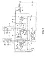
- FIG. 1 is a circuit diagram showing a hydraulic control circuit of a hybrid construction machine according to the embodiment of the present invention.
- a first main pump MP1 and a second main pump MP2 of a variable-capacity type are provided in the hydraulic control circuit.
- the first main pump MP1 is directly connected to a first circuit system S1 via a first supply passage 1. Out of an input port 2a and an output port 2b provided in a first logic valve 2, the output port 2b is connected to the first supply passage 1. A plurality of operation valves 52 to 56 are connected to the first circuit system S1.
- the second main pump MP2 is directly connected to a second circuit system S2 by way of a second supply passage 3.
- a second logic valve 4 is provided at an intermediate position of the second supply passage 3.
- An input port 4a of the second logic valve 4 is connected to the second supply passage 3 on the upstream side of the second logic valve 4 and an output port 4b of the second logic valve 4 is connected to the second supply passage 3 on the downstream side of the second logic valve 4.
- a plurality of operation valves 59 to 62 are connected to the second circuit system.
- the hydraulic control circuit includes an assist pump AP in addition to the first and second main pumps MP1, MP2.
- the assist pump AP is rotated by a drive force of a motor generator MG.
- the motor generator MG is rotated by a drive force of a hydraulic motor M.
- the hydraulic motor M is connected to the second supply passage 3 on the upstream side of the second logic valve 4 by way of a connection passage 6 connected to a switching valve 5.
- the motor generator MG is connected to a battery 64 via an inverter I. Accordingly, if the hydraulic motor M rotates, the motor generator MG rotates to generate power and the generated power is stored into the battery 64 via the inverter I.
- a joint passage 7 is connected to the assist pump AP.
- the joint passage 7 branches off into a branch passage 7a and a branch passage 7b.
- One branch passage 7a is directly connected to the input port 2a of the first logic valve 2.
- the other branch passage 7b is connected to the second supply passage 3 on the upstream side of the second logic valve 4 by way of the switching valve 5 and a check valve 8 provided downstream of the switching valve 5.
- the check valve 8 permits only a flow from the assist pump AP to the second supply passage 3.
- the switching valve 5 is a three-position switching valve and keeps the branch passage 7b in a state of communication and cuts off the connection passage 6 when being at a shown neutral position. This causes discharged oil from the assist pump AP to be supplied to the input port 2a of the first logic valve 2 by way of the one branch passage 7a and to the second supply passage 3 on the upstream side of the second logic valve 4 by way of the other branch passage 7b.
- connection passage 6 is set in a state of communication. This allows the second supply passage 3 on the upstream side of the second logic valve 4 to communicate with the hydraulic motor M via the connection passage 6.
- both the connection passage 6 and the branch passage 7b are cut off.
- the assist pump AP is connected to the second main pump MP2 via the branch passage 7b including the check valve 8. Since the opening of the check valve 8 is limited, a pressure loss in a path from the assist pump AP to the second main pump MP2 becomes larger than a pressure loss in a path from the assist pump AP to the first main pump MP1, whereby a pressure balance between the both may be possibly lost.
- the branch passage 7b includes a bypass passage 9 branching off between the switching valve 5 and the check valve 8 in the present embodiment.
- the bypass passage 9 is directly connected to the second supply passage 3 on the downstream side of the second logic valve 4.
- a check valve 10 for permitting only a flow from the assist pump AP to the second supply passage 3 on the downstream side of the second logic valve 4 is provided in the bypass passage 9.
- the switching valve 5 includes a pilot chamber 5a and a pilot chamber 5b, an electromagnetic switching valve 11 is connected to the pilot chamber 5a and an electromagnetic switching valve 12 is connected to the pilot chamber 5b.
- a pilot pressure from a pilot pump PP is introduced to the switching valve 5 via the electromagnetic switching valves 11, 12.
- the switching valve 5 is switched to any one of the neutral position, the left position and the right position by the action of the pilot pressure.
- a pilot chamber 2c of the first logic valve 2 is connected to the first supply passage 1 via an on-off valve 13.
- a pilot chamber 4c of the second logic valve 4 is connected to the second supply passage 3 via an on-off valve 14.
- the on-off valves 13, 14 have a fully open position, a closed position and a throttle control position and are switched to the fully open position, the closed position or the throttle control position according to a pilot pressure in the corresponding pilot chambers 13a, 14a.
- Electromagnetic switching valves 11, 15 are connected to the respective pilot chambers 13a, 14a of the on-off valves 13, 14.
- the on-off valves 13, 14 are switched by the pilot pressure from the pilot pump PP introduced via the electromagnetic switching valves 11, 15.
- the electromagnetic switching valve 11 is also connected to one pilot chamber 5a of the switching valve 5.
- the electromagnetic switching valve 11 When the electromagnetic switching valve 11 is at a neutral position shown in FIG. 1 , the pilot chamber 5a of the switching valve 5 and the pilot chamber 14a of the on-off valve 14 respectively communicate with a drain passage 16. On the other hand, when a solenoid of the electromagnetic switching valve 11 is excited by a control signal from a controller C, the electromagnetic switching valve 11 is switched to a switch position. In this way, the pilot pressure of the pilot pump PP is introduced to the both pilot chambers 5a, 14a.
- the electromagnetic switching valve 15 When the electromagnetic switching valve 15 is at a neutral position shown in FIG. 1 , the pilot chamber 13a of the on-off valve 13 communicates with the drain passage 16. On the other hand, when a solenoid of the electromagnetic switching valve 15 is excited by a control signal from the controller C, the electromagnetic switching valve 15 is switched to a switch position. In this way, the pilot pressure of the pilot pump PP is introduced to the pilot chamber 13a of the on-off valve 13.
- the controller C outputs a control signal corresponding to the operation of the operator.
- the operator can switch each of the electromagnetic switching valves 11, 12 and 15 to the switch position simultaneously and can also switch them individually.
- the controller C In the case of causing the motor generator MG to fulfill a power generation function, the controller C outputs a control signal to switch the electromagnetic switching valve 11 to the switch position.
- the electromagnetic switching valve 11 When the electromagnetic switching valve 11 is switched to the switch position, the pilot pressure of the pilot pump PP is introduced to each of the one pilot chamber 5a of the switching valve 5 and the pilot chamber 14a of the on-off valve 14.
- the controller C keeps a solenoid of the electromagnetic switching valve 12 in a non-exciting state and allows the other pilot chamber 5b of the switching valve 5 to communicate with the drain passage 16.
- the on-off valve 14 When the pilot pressure is introduced to the pilot chamber 14a of the on-off valve 14, the on-off valve 14 is switched to the closed position by the action of the pressure in the pilot chamber 14a. Then, the pilot chamber 4c of the second logic valve 4 is closed, wherefore the second logic valve 4 is kept in a closed state.
- the discharged oil from the second main pump MP2 is supplied to the hydraulic motor M by way of the connection passage 6 and the switching valve 5 without being introduced to the second circuit system S2, thereby rotating the hydraulic motor M. If the hydraulic motor M rotates, the motor generator MG rotates to generate power and the generated power is stored into the battery 64 via the inverter I.
- the controller C outputs a control signal to set all of the solenoids of the electromagnetic switching valves 11, 12 and 15 in the non-exciting state.
- the electromagnetic switching valves 11, 12 and 15 are kept at the shown neutral position and the pilot chambers 5a, 5b of the switching valve 5 and the pilot chambers 13a, 14a of the on-off valves 13, 14 communicate with the drain passage 16.
- the on-off valve 13 Since the pilot chamber 13a of the on-off valve 13 communicates with the drain passage 16 as described above, the on-off valve 13 is kept at the fully open position that is the shown neutral position. If the discharged oil from the assist pump AP flows into the first logic valve 2 from the branch passage 7a in this state, the first logic valve 2 is opened.
- the discharged oil from the assist pump AP supplied to the branch passage 7a joins the first supply passage 1 by way of the first logic valve 2 and is supplied to the first circuit system S1.
- the switching valve 5 since the pilot chambers 5a, 5b of the switching valve 5 communicate with the drain passage 16 as described above, the switching valve 5 is kept at the shown neutral position and the branch passage 7b of the joint passage 7 and the bypass passage 9 communicate with the assist pump AP. At this time, since the pilot chamber 14a of the on-off valve 14 also communicates with the drain passage 16, the on-off valve 14 is kept at the fully open position that is the shown neutral position. If the on-off valve 14 is kept at the fully open position, the pilot chamber 4c of the second logic valve 4 communicates with the second supply passage 3, wherefore a pressure in the branch passage 7b acts on the second logic valve 4 to open the second logic valve 4.
- the discharged oil from the assist pump AP is supplied from the branch passage 7b to the second circuit system S2 by way of the second logic valve 4 and directly supplied to the second circuit system S2 through the bypass passage 9.
- the opening of the electromagnetic switching valve 11 or 15 can be controlled according to throttle opening.
- the pressures of the first and second circuit systems S1, S2 can be controlled in a comprehensive manner, for example, by reducing the opening of the first logic valve 2 and actively increasing the pressure loss at the first logic valve 2 side.
- the pressures of the first and second circuit systems S1, S2 can be controlled as necessary by changing a combination of the openings of the on-off valves 13, 14.
- an operator can operate with almost the same feeling as the operation feeling of the existing system by controlling the on-off valves 13, 14.
- a comfortable operation can be realized without deteriorating the operation feeling of the operator.
- a pilot pressure for keeping the on-off valve 14 at the throttle control position is set at a pressure in a range to keep the switching valve 5 at or near the shown neutral position. In this way, the on-off valve 14 can be kept at the throttle control position and it can be prevented that the switching valve 5 is switched to a position other than the neutral position and the discharged oil from the assist pump AP is not introduced to the second logic valve 4.
- the electromagnetic switching valve 11 is kept at the shown neutral position and the electromagnetic switching valve 12 is switched to the switch position, the one pilot chamber 5a of the switching valve 5 communicates with the drain passage 16 and the other pilot chamber 5b communicates with the pilot pump PP. Accordingly, the switching valve 5 is switched to the shown right position to cut off the communication between the hydraulic motor M and the second main pump MP2, between the assist pump AP and the side downstream of the branch passage 7b, and between the assist pump AP and the bypass passage 9. Thus, the discharged oil from the assist pump AP is supplied only to the first logic valve 2 by way of the branch passage 7a.
Landscapes
- Engineering & Computer Science (AREA)
- General Engineering & Computer Science (AREA)
- Mining & Mineral Resources (AREA)
- Civil Engineering (AREA)
- Structural Engineering (AREA)
- Physics & Mathematics (AREA)
- Fluid Mechanics (AREA)
- Mechanical Engineering (AREA)
- Chemical & Material Sciences (AREA)
- Analytical Chemistry (AREA)
- Fluid-Pressure Circuits (AREA)
- Operation Control Of Excavators (AREA)
Applications Claiming Priority (2)
| Application Number | Priority Date | Filing Date | Title |
|---|---|---|---|
| JP2012013185A JP5791530B2 (ja) | 2012-01-25 | 2012-01-25 | 建設機械の制御装置 |
| PCT/JP2013/051101 WO2013111707A1 (ja) | 2012-01-25 | 2013-01-21 | ハイブリッド建設機械 |
Publications (3)
| Publication Number | Publication Date |
|---|---|
| EP2808563A1 true EP2808563A1 (de) | 2014-12-03 |
| EP2808563A4 EP2808563A4 (de) | 2015-12-02 |
| EP2808563B1 EP2808563B1 (de) | 2017-10-18 |
Family
ID=48873427
Family Applications (1)
| Application Number | Title | Priority Date | Filing Date |
|---|---|---|---|
| EP13741345.6A Not-in-force EP2808563B1 (de) | 2012-01-25 | 2013-01-21 | Hybridbaumaschine |
Country Status (6)
| Country | Link |
|---|---|
| US (1) | US9441648B2 (de) |
| EP (1) | EP2808563B1 (de) |
| JP (1) | JP5791530B2 (de) |
| KR (1) | KR101653472B1 (de) |
| CN (1) | CN104067002B (de) |
| WO (1) | WO2013111707A1 (de) |
Families Citing this family (1)
| Publication number | Priority date | Publication date | Assignee | Title |
|---|---|---|---|---|
| CN103276765B (zh) * | 2013-06-03 | 2015-07-15 | 江西宜春重工集团有限公司 | 装载机的铲掘联动液压操作系统 |
Family Cites Families (9)
| Publication number | Priority date | Publication date | Assignee | Title |
|---|---|---|---|---|
| JPH0517442Y2 (de) | 1986-12-18 | 1993-05-11 | ||
| JPH09151488A (ja) | 1995-11-22 | 1997-06-10 | Komatsu Ltd | 油圧ショベルの油圧回路 |
| JPH09151489A (ja) * | 1995-11-22 | 1997-06-10 | Komatsu Ltd | 油圧ショベルの油圧回路 |
| JP4642269B2 (ja) * | 2001-05-21 | 2011-03-02 | 株式会社小松製作所 | 建設機械の油圧回路 |
| US20090288408A1 (en) * | 2005-06-06 | 2009-11-26 | Shin Caterpillar Mitsubishi Ltd. | Hydraulic circuit, energy recovery device, and hydraulic circuit for work machine |
| JP5258341B2 (ja) * | 2008-03-26 | 2013-08-07 | カヤバ工業株式会社 | ハイブリッド建設機械の制御装置 |
| JP4942699B2 (ja) * | 2008-04-25 | 2012-05-30 | カヤバ工業株式会社 | ハイブリッド建設機械の制御装置 |
| JP5410329B2 (ja) * | 2010-02-23 | 2014-02-05 | カヤバ工業株式会社 | ハイブリッド建設機械の制御装置 |
| JP5350320B2 (ja) | 2010-05-20 | 2013-11-27 | カヤバ工業株式会社 | 建設機械の制御装置 |
-
2012
- 2012-01-25 JP JP2012013185A patent/JP5791530B2/ja not_active Expired - Fee Related
-
2013
- 2013-01-21 KR KR1020147020637A patent/KR101653472B1/ko not_active Expired - Fee Related
- 2013-01-21 EP EP13741345.6A patent/EP2808563B1/de not_active Not-in-force
- 2013-01-21 CN CN201380006413.4A patent/CN104067002B/zh not_active Expired - Fee Related
- 2013-01-21 US US14/373,945 patent/US9441648B2/en not_active Expired - Fee Related
- 2013-01-21 WO PCT/JP2013/051101 patent/WO2013111707A1/ja not_active Ceased
Also Published As
| Publication number | Publication date |
|---|---|
| KR101653472B1 (ko) | 2016-09-01 |
| US20150033726A1 (en) | 2015-02-05 |
| WO2013111707A1 (ja) | 2013-08-01 |
| CN104067002A (zh) | 2014-09-24 |
| US9441648B2 (en) | 2016-09-13 |
| KR20140116142A (ko) | 2014-10-01 |
| JP2013151985A (ja) | 2013-08-08 |
| CN104067002B (zh) | 2016-04-13 |
| EP2808563B1 (de) | 2017-10-18 |
| EP2808563A4 (de) | 2015-12-02 |
| JP5791530B2 (ja) | 2015-10-07 |
Similar Documents
| Publication | Publication Date | Title |
|---|---|---|
| US9228323B2 (en) | Control system for construction machine | |
| JP5357864B2 (ja) | 建設機械の油圧回路 | |
| US9932995B2 (en) | Hydraulic excavator drive system | |
| EP2157245B1 (de) | Hydrauliksystem für ein Baugerät | |
| EP2811171B1 (de) | Hybridbaumaschine | |
| EP2107170B1 (de) | Hydraulische antriebsanordnung für eine zivilbau- oder erdbewegungsmaschine. | |
| US20100313556A1 (en) | Construction equipment having electric control lever | |
| US20160251833A1 (en) | Hydraulic drive system of construction machine | |
| EP2808563B1 (de) | Hybridbaumaschine | |
| US20040261405A1 (en) | Hydraulic circuit for heavy equipment option apparatus using boom confluence spool | |
| JP2005121043A (ja) | 油圧回路及びその合流弁 | |
| JP2010196780A (ja) | 建設機械の油圧制御装置 | |
| JP2019190226A (ja) | 流体圧制御装置 | |
| JP2011241947A (ja) | 建設機械の制御装置 | |
| JP5791360B2 (ja) | 建設機械の油圧回路 | |
| JP2014092260A (ja) | パワーショベルの流体圧制御装置 | |
| KR101728596B1 (ko) | 파워 셔블의 제어 밸브 장치 | |
| JP4926627B2 (ja) | 電油システム | |
| JP5036486B2 (ja) | 油圧回路および建設機械用油圧制御装置 | |
| KR20150075624A (ko) | 굴삭기의 메인 컨트롤 밸브 | |
| JP2004278241A (ja) | 建設機械の油圧回路 | |
| JP2007205414A (ja) | 油圧アクチュエータ用制御回路 |
Legal Events
| Date | Code | Title | Description |
|---|---|---|---|
| PUAI | Public reference made under article 153(3) epc to a published international application that has entered the european phase |
Free format text: ORIGINAL CODE: 0009012 |
|
| 17P | Request for examination filed |
Effective date: 20140731 |
|
| AK | Designated contracting states |
Kind code of ref document: A1 Designated state(s): AL AT BE BG CH CY CZ DE DK EE ES FI FR GB GR HR HU IE IS IT LI LT LU LV MC MK MT NL NO PL PT RO RS SE SI SK SM TR |
|
| DAX | Request for extension of the european patent (deleted) | ||
| RA4 | Supplementary search report drawn up and despatched (corrected) |
Effective date: 20151103 |
|
| RIC1 | Information provided on ipc code assigned before grant |
Ipc: F15B 11/02 20060101ALI20151028BHEP Ipc: F15B 11/17 20060101ALI20151028BHEP Ipc: E02F 9/22 20060101ALI20151028BHEP Ipc: E02F 9/20 20060101ALI20151028BHEP Ipc: F15B 21/14 20060101AFI20151028BHEP |
|
| RAP1 | Party data changed (applicant data changed or rights of an application transferred) |
Owner name: KYB CORPORATION |
|
| GRAP | Despatch of communication of intention to grant a patent |
Free format text: ORIGINAL CODE: EPIDOSNIGR1 |
|
| INTG | Intention to grant announced |
Effective date: 20170629 |
|
| RIN1 | Information on inventor provided before grant (corrected) |
Inventor name: FUKUDA, SHUNSUKE Inventor name: YOSHIDA, NOBUYOSHI |
|
| GRAS | Grant fee paid |
Free format text: ORIGINAL CODE: EPIDOSNIGR3 |
|
| GRAA | (expected) grant |
Free format text: ORIGINAL CODE: 0009210 |
|
| AK | Designated contracting states |
Kind code of ref document: B1 Designated state(s): AL AT BE BG CH CY CZ DE DK EE ES FI FR GB GR HR HU IE IS IT LI LT LU LV MC MK MT NL NO PL PT RO RS SE SI SK SM TR |
|
| REG | Reference to a national code |
Ref country code: GB Ref legal event code: FG4D |
|
| REG | Reference to a national code |
Ref country code: CH Ref legal event code: EP |
|
| REG | Reference to a national code |
Ref country code: AT Ref legal event code: REF Ref document number: 938201 Country of ref document: AT Kind code of ref document: T Effective date: 20171115 Ref country code: IE Ref legal event code: FG4D |
|
| REG | Reference to a national code |
Ref country code: DE Ref legal event code: R096 Ref document number: 602013028114 Country of ref document: DE |
|
| REG | Reference to a national code |
Ref country code: NL Ref legal event code: MP Effective date: 20171018 |
|
| REG | Reference to a national code |
Ref country code: LT Ref legal event code: MG4D |
|
| REG | Reference to a national code |
Ref country code: AT Ref legal event code: MK05 Ref document number: 938201 Country of ref document: AT Kind code of ref document: T Effective date: 20171018 |
|
| PG25 | Lapsed in a contracting state [announced via postgrant information from national office to epo] |
Ref country code: NL Free format text: LAPSE BECAUSE OF FAILURE TO SUBMIT A TRANSLATION OF THE DESCRIPTION OR TO PAY THE FEE WITHIN THE PRESCRIBED TIME-LIMIT Effective date: 20171018 |
|
| PG25 | Lapsed in a contracting state [announced via postgrant information from national office to epo] |
Ref country code: SE Free format text: LAPSE BECAUSE OF FAILURE TO SUBMIT A TRANSLATION OF THE DESCRIPTION OR TO PAY THE FEE WITHIN THE PRESCRIBED TIME-LIMIT Effective date: 20171018 Ref country code: ES Free format text: LAPSE BECAUSE OF FAILURE TO SUBMIT A TRANSLATION OF THE DESCRIPTION OR TO PAY THE FEE WITHIN THE PRESCRIBED TIME-LIMIT Effective date: 20171018 Ref country code: FI Free format text: LAPSE BECAUSE OF FAILURE TO SUBMIT A TRANSLATION OF THE DESCRIPTION OR TO PAY THE FEE WITHIN THE PRESCRIBED TIME-LIMIT Effective date: 20171018 Ref country code: NO Free format text: LAPSE BECAUSE OF FAILURE TO SUBMIT A TRANSLATION OF THE DESCRIPTION OR TO PAY THE FEE WITHIN THE PRESCRIBED TIME-LIMIT Effective date: 20180118 Ref country code: LT Free format text: LAPSE BECAUSE OF FAILURE TO SUBMIT A TRANSLATION OF THE DESCRIPTION OR TO PAY THE FEE WITHIN THE PRESCRIBED TIME-LIMIT Effective date: 20171018 |
|
| PG25 | Lapsed in a contracting state [announced via postgrant information from national office to epo] |
Ref country code: IS Free format text: LAPSE BECAUSE OF FAILURE TO SUBMIT A TRANSLATION OF THE DESCRIPTION OR TO PAY THE FEE WITHIN THE PRESCRIBED TIME-LIMIT Effective date: 20180218 Ref country code: GR Free format text: LAPSE BECAUSE OF FAILURE TO SUBMIT A TRANSLATION OF THE DESCRIPTION OR TO PAY THE FEE WITHIN THE PRESCRIBED TIME-LIMIT Effective date: 20180119 Ref country code: HR Free format text: LAPSE BECAUSE OF FAILURE TO SUBMIT A TRANSLATION OF THE DESCRIPTION OR TO PAY THE FEE WITHIN THE PRESCRIBED TIME-LIMIT Effective date: 20171018 Ref country code: AT Free format text: LAPSE BECAUSE OF FAILURE TO SUBMIT A TRANSLATION OF THE DESCRIPTION OR TO PAY THE FEE WITHIN THE PRESCRIBED TIME-LIMIT Effective date: 20171018 Ref country code: RS Free format text: LAPSE BECAUSE OF FAILURE TO SUBMIT A TRANSLATION OF THE DESCRIPTION OR TO PAY THE FEE WITHIN THE PRESCRIBED TIME-LIMIT Effective date: 20171018 Ref country code: BG Free format text: LAPSE BECAUSE OF FAILURE TO SUBMIT A TRANSLATION OF THE DESCRIPTION OR TO PAY THE FEE WITHIN THE PRESCRIBED TIME-LIMIT Effective date: 20180118 Ref country code: LV Free format text: LAPSE BECAUSE OF FAILURE TO SUBMIT A TRANSLATION OF THE DESCRIPTION OR TO PAY THE FEE WITHIN THE PRESCRIBED TIME-LIMIT Effective date: 20171018 |
|
| REG | Reference to a national code |
Ref country code: DE Ref legal event code: R097 Ref document number: 602013028114 Country of ref document: DE |
|
| PG25 | Lapsed in a contracting state [announced via postgrant information from national office to epo] |
Ref country code: CZ Free format text: LAPSE BECAUSE OF FAILURE TO SUBMIT A TRANSLATION OF THE DESCRIPTION OR TO PAY THE FEE WITHIN THE PRESCRIBED TIME-LIMIT Effective date: 20171018 Ref country code: EE Free format text: LAPSE BECAUSE OF FAILURE TO SUBMIT A TRANSLATION OF THE DESCRIPTION OR TO PAY THE FEE WITHIN THE PRESCRIBED TIME-LIMIT Effective date: 20171018 Ref country code: SK Free format text: LAPSE BECAUSE OF FAILURE TO SUBMIT A TRANSLATION OF THE DESCRIPTION OR TO PAY THE FEE WITHIN THE PRESCRIBED TIME-LIMIT Effective date: 20171018 Ref country code: DK Free format text: LAPSE BECAUSE OF FAILURE TO SUBMIT A TRANSLATION OF THE DESCRIPTION OR TO PAY THE FEE WITHIN THE PRESCRIBED TIME-LIMIT Effective date: 20171018 |
|
| PLBE | No opposition filed within time limit |
Free format text: ORIGINAL CODE: 0009261 |
|
| STAA | Information on the status of an ep patent application or granted ep patent |
Free format text: STATUS: NO OPPOSITION FILED WITHIN TIME LIMIT |
|
| PG25 | Lapsed in a contracting state [announced via postgrant information from national office to epo] |
Ref country code: RO Free format text: LAPSE BECAUSE OF FAILURE TO SUBMIT A TRANSLATION OF THE DESCRIPTION OR TO PAY THE FEE WITHIN THE PRESCRIBED TIME-LIMIT Effective date: 20171018 Ref country code: PL Free format text: LAPSE BECAUSE OF FAILURE TO SUBMIT A TRANSLATION OF THE DESCRIPTION OR TO PAY THE FEE WITHIN THE PRESCRIBED TIME-LIMIT Effective date: 20171018 Ref country code: SM Free format text: LAPSE BECAUSE OF FAILURE TO SUBMIT A TRANSLATION OF THE DESCRIPTION OR TO PAY THE FEE WITHIN THE PRESCRIBED TIME-LIMIT Effective date: 20171018 Ref country code: IT Free format text: LAPSE BECAUSE OF FAILURE TO SUBMIT A TRANSLATION OF THE DESCRIPTION OR TO PAY THE FEE WITHIN THE PRESCRIBED TIME-LIMIT Effective date: 20171018 |
|
| REG | Reference to a national code |
Ref country code: CH Ref legal event code: PL |
|
| 26N | No opposition filed |
Effective date: 20180719 |
|
| GBPC | Gb: european patent ceased through non-payment of renewal fee |
Effective date: 20180121 |
|
| PG25 | Lapsed in a contracting state [announced via postgrant information from national office to epo] |
Ref country code: FR Free format text: LAPSE BECAUSE OF NON-PAYMENT OF DUE FEES Effective date: 20180131 Ref country code: LU Free format text: LAPSE BECAUSE OF NON-PAYMENT OF DUE FEES Effective date: 20180121 |
|
| REG | Reference to a national code |
Ref country code: IE Ref legal event code: MM4A |
|
| REG | Reference to a national code |
Ref country code: FR Ref legal event code: ST Effective date: 20180928 |
|
| REG | Reference to a national code |
Ref country code: BE Ref legal event code: MM Effective date: 20180131 |
|
| PG25 | Lapsed in a contracting state [announced via postgrant information from national office to epo] |
Ref country code: CH Free format text: LAPSE BECAUSE OF NON-PAYMENT OF DUE FEES Effective date: 20180131 Ref country code: BE Free format text: LAPSE BECAUSE OF NON-PAYMENT OF DUE FEES Effective date: 20180131 Ref country code: SI Free format text: LAPSE BECAUSE OF FAILURE TO SUBMIT A TRANSLATION OF THE DESCRIPTION OR TO PAY THE FEE WITHIN THE PRESCRIBED TIME-LIMIT Effective date: 20171018 Ref country code: LI Free format text: LAPSE BECAUSE OF NON-PAYMENT OF DUE FEES Effective date: 20180131 Ref country code: GB Free format text: LAPSE BECAUSE OF NON-PAYMENT OF DUE FEES Effective date: 20180121 |
|
| PG25 | Lapsed in a contracting state [announced via postgrant information from national office to epo] |
Ref country code: IE Free format text: LAPSE BECAUSE OF NON-PAYMENT OF DUE FEES Effective date: 20180121 |
|
| PGFP | Annual fee paid to national office [announced via postgrant information from national office to epo] |
Ref country code: DE Payment date: 20190129 Year of fee payment: 7 |
|
| PG25 | Lapsed in a contracting state [announced via postgrant information from national office to epo] |
Ref country code: MC Free format text: LAPSE BECAUSE OF FAILURE TO SUBMIT A TRANSLATION OF THE DESCRIPTION OR TO PAY THE FEE WITHIN THE PRESCRIBED TIME-LIMIT Effective date: 20171018 |
|
| PG25 | Lapsed in a contracting state [announced via postgrant information from national office to epo] |
Ref country code: MT Free format text: LAPSE BECAUSE OF NON-PAYMENT OF DUE FEES Effective date: 20180121 |
|
| PG25 | Lapsed in a contracting state [announced via postgrant information from national office to epo] |
Ref country code: TR Free format text: LAPSE BECAUSE OF FAILURE TO SUBMIT A TRANSLATION OF THE DESCRIPTION OR TO PAY THE FEE WITHIN THE PRESCRIBED TIME-LIMIT Effective date: 20171018 |
|
| PG25 | Lapsed in a contracting state [announced via postgrant information from national office to epo] |
Ref country code: PT Free format text: LAPSE BECAUSE OF FAILURE TO SUBMIT A TRANSLATION OF THE DESCRIPTION OR TO PAY THE FEE WITHIN THE PRESCRIBED TIME-LIMIT Effective date: 20171018 Ref country code: HU Free format text: LAPSE BECAUSE OF FAILURE TO SUBMIT A TRANSLATION OF THE DESCRIPTION OR TO PAY THE FEE WITHIN THE PRESCRIBED TIME-LIMIT; INVALID AB INITIO Effective date: 20130121 |
|
| PG25 | Lapsed in a contracting state [announced via postgrant information from national office to epo] |
Ref country code: CY Free format text: LAPSE BECAUSE OF FAILURE TO SUBMIT A TRANSLATION OF THE DESCRIPTION OR TO PAY THE FEE WITHIN THE PRESCRIBED TIME-LIMIT Effective date: 20171018 Ref country code: MK Free format text: LAPSE BECAUSE OF NON-PAYMENT OF DUE FEES Effective date: 20171018 |
|
| PG25 | Lapsed in a contracting state [announced via postgrant information from national office to epo] |
Ref country code: AL Free format text: LAPSE BECAUSE OF FAILURE TO SUBMIT A TRANSLATION OF THE DESCRIPTION OR TO PAY THE FEE WITHIN THE PRESCRIBED TIME-LIMIT Effective date: 20171018 |
|
| REG | Reference to a national code |
Ref country code: DE Ref legal event code: R119 Ref document number: 602013028114 Country of ref document: DE |
|
| PG25 | Lapsed in a contracting state [announced via postgrant information from national office to epo] |
Ref country code: DE Free format text: LAPSE BECAUSE OF NON-PAYMENT OF DUE FEES Effective date: 20200801 |