EP2808461A1 - Dachfenster mit Wasserumleitungselement - Google Patents
Dachfenster mit Wasserumleitungselement Download PDFInfo
- Publication number
- EP2808461A1 EP2808461A1 EP14170145.8A EP14170145A EP2808461A1 EP 2808461 A1 EP2808461 A1 EP 2808461A1 EP 14170145 A EP14170145 A EP 14170145A EP 2808461 A1 EP2808461 A1 EP 2808461A1
- Authority
- EP
- European Patent Office
- Prior art keywords
- pane
- diversion
- roof window
- window according
- diversion member
- Prior art date
- Legal status (The legal status is an assumption and is not a legal conclusion. Google has not performed a legal analysis and makes no representation as to the accuracy of the status listed.)
- Granted
Links
- XLYOFNOQVPJJNP-UHFFFAOYSA-N water Substances O XLYOFNOQVPJJNP-UHFFFAOYSA-N 0.000 title claims description 22
- 238000009423 ventilation Methods 0.000 claims abstract description 30
- 229920003051 synthetic elastomer Polymers 0.000 claims description 2
- 239000005061 synthetic rubber Substances 0.000 claims description 2
- 229920001971 elastomer Polymers 0.000 description 8
- 239000000463 material Substances 0.000 description 8
- 239000005060 rubber Substances 0.000 description 8
- 239000011324 bead Substances 0.000 description 5
- 238000007789 sealing Methods 0.000 description 4
- 230000000149 penetrating effect Effects 0.000 description 3
- 229920002943 EPDM rubber Polymers 0.000 description 2
- 239000004698 Polyethylene Substances 0.000 description 2
- 239000004743 Polypropylene Substances 0.000 description 2
- 229920000573 polyethylene Polymers 0.000 description 2
- -1 polypropylene Polymers 0.000 description 2
- 229920001155 polypropylene Polymers 0.000 description 2
- 229920002635 polyurethane Polymers 0.000 description 2
- 239000004814 polyurethane Substances 0.000 description 2
- 229920000459 Nitrile rubber Polymers 0.000 description 1
- 239000010426 asphalt Substances 0.000 description 1
- 238000007664 blowing Methods 0.000 description 1
- 238000010276 construction Methods 0.000 description 1
- 238000013016 damping Methods 0.000 description 1
- 230000006866 deterioration Effects 0.000 description 1
- 230000009977 dual effect Effects 0.000 description 1
- 229920001821 foam rubber Polymers 0.000 description 1
- 238000009434 installation Methods 0.000 description 1
- 239000002184 metal Substances 0.000 description 1
- 239000002991 molded plastic Substances 0.000 description 1
- 239000004033 plastic Substances 0.000 description 1
- 229920003023 plastic Polymers 0.000 description 1
- 229920000642 polymer Polymers 0.000 description 1
- 239000004800 polyvinyl chloride Substances 0.000 description 1
- 238000001556 precipitation Methods 0.000 description 1
- 230000005855 radiation Effects 0.000 description 1
- 230000001105 regulatory effect Effects 0.000 description 1
- 230000000717 retained effect Effects 0.000 description 1
- 238000009420 retrofitting Methods 0.000 description 1
- 238000004904 shortening Methods 0.000 description 1
- 229920002379 silicone rubber Polymers 0.000 description 1
- 239000004945 silicone rubber Substances 0.000 description 1
- 239000007787 solid Substances 0.000 description 1
- 238000005728 strengthening Methods 0.000 description 1
- 230000007704 transition Effects 0.000 description 1
- 230000000007 visual effect Effects 0.000 description 1
Images


Classifications
-
- E—FIXED CONSTRUCTIONS
- E04—BUILDING
- E04D—ROOF COVERINGS; SKY-LIGHTS; GUTTERS; ROOF-WORKING TOOLS
- E04D13/00—Special arrangements or devices in connection with roof coverings; Protection against birds; Roof drainage ; Sky-lights
- E04D13/03—Sky-lights; Domes; Ventilating sky-lights
- E04D13/0325—Sky-lights; Domes; Ventilating sky-lights provided with ventilating means
-
- E—FIXED CONSTRUCTIONS
- E06—DOORS, WINDOWS, SHUTTERS, OR ROLLER BLINDS IN GENERAL; LADDERS
- E06B—FIXED OR MOVABLE CLOSURES FOR OPENINGS IN BUILDINGS, VEHICLES, FENCES OR LIKE ENCLOSURES IN GENERAL, e.g. DOORS, WINDOWS, BLINDS, GATES
- E06B7/00—Special arrangements or measures in connection with doors or windows
- E06B7/02—Special arrangements or measures in connection with doors or windows for providing ventilation, e.g. through double windows; Arrangement of ventilation roses
- E06B7/10—Special arrangements or measures in connection with doors or windows for providing ventilation, e.g. through double windows; Arrangement of ventilation roses by special construction of the frame members
Definitions
- the present invention relates to a roof window, comprising a frame, a sash carrying a pane and a covering including a frame top covering member arranged on an exterior side of a frame top member and covering an exterior side of a sash top member, where a ventilation passage with an exterior ventilation opening is provided between the frame top covering member and the sash top member.
- the frame and the sash normally each comprise a top member, a bottom member and two side members forming rectangular units and the window has an interior side intended to face the interior of a building and exterior side intended to face the exterior of the building.
- Windows of this type are known for example from WO2008/133539A2 and EP2317026B1 , where the amount of air passing through the ventilation passages are regulated by baffles, but windows with a permanent unobstructed ventilation passage are also known.
- a diversion member is provided between the pane and the frame top covering member and extending across the width of the window substantially in parallel with the sash top member, said diversion member having a first portion intended to be attached directly or indirectly to the sash top member and a second portion with a free distal edge and a fixed proximate edge, said second portion forming an extension of the first portion in a direction away from the frame top covering member and the pane in the closed state of the window so as to substantially cover for the ventilation opening when seen in a direction parallel to the pane but leaving an opening when seen in a direction perpendicular to the pane.
- the second portion of the diversion member having a free distal edge projecting in a direction away from the pane and the frame top covering member and hence also the sash top member indicates that it preferably can be placed or arranged at an angle to the plane of the pane, thus forming a substantially wedge-shaped space between the second portion and the exterior side of the pane, i.e. below the first portion in the direction of slope of the window in the mounted state.
- Any water on the exterior surface of the pane, which is forced upwards on the pane by wind, will end up at the space between the second portion of the diversion member and the exterior side of the pane and hence be prevented from entering the ventilation opening, which is located on the opposite side of the second portion.
- the water will only be able to penetrate into the ventilation passage if it builds up to a level, which is higher above the exterior surface of the pane than the free distal edge of the second portion of the diversion member.
- the angle between the overall direction of the second portion of the diversion member and the exterior side of the pane is approximately 45 degrees. This will provide a good balance between the need for maintaining a suitable ventilation opening and preventing water from entering the construction, but it is envisaged that any angle between 20 and 70 degrees may provide satisfactory results.
- the frame top covering member usually has a leg projecting from an exterior portion of the covering member towards the pane so that the ventilation opening is defined as the gap between the lower edge of this leg and the exterior surface of the pane or a glazing profile overlapping the edge of the pane.
- the first portion of the diversion member will then normally be located underneath the frame top covering member, behind the projecting leg, while the second portion will be locate on the opposite side of the leg above the exterior pane surface and not covered by the frame top covering member.
- the diversion member extends across the width of the window is not to be understood as if it has to extend over the entire width of the window, but to ensure a good visual impression of the window this will usually be the case. If the ventilation opening is present over only a part or parts of the width of the window it may be sufficient to provide the diversion member or members at these parts.
- the first portion and the second portion do not need to have the same length.
- the first portion may in some cases advantageously be interrupted at a distance from the ends of the second portion to facilitate attachment of the diversion member and give room for other parts of the window.
- the first portion may be shortened during installation if needed and may be provided with indications and/or weaknings to assist such a shortening.
- the second portion preferably has the shape of a gutter, which is open towards the exterior side of the window and open at the ends. This allows a considerable amount of water to collect in the gutter and to be drained off at the ends, where it will run out onto the pane or onto glazing profiles, diversion members or the like used as at sides of the window.
- the distance between an exterior side of the second portion forming the gutter and a lower edge of a leg of the frame top covering member projecting towards the pane is substantially constant when seen in a plane perpendicular to the length axis of the frame top member.
- the surface of the gutter has the cross-sectional shape of a sector of a circle. Other shapes are, however, also possible.
- one or more drainage opening(s) at the bottom of the gutter, preferably at a distance from its ends, and allowing water in the gutter to drain out onto the exterior surface of the pane. This will of course involve the risk of water penetrating from the pane and into the gutter, but in case of extreme wind or water pressure on the pane this may be advantageous since it will reduce the pressure on the diversion member and hence potentially prevent it from being torn loose.
- the diversion member is preferably made from synthetic rubber, such as rubber polymer modified bitumen (RPMB), polyurethane (PUR), ethylene propylene diene monomer (EPDM), nitrile rubber or silicone rubber, but it is also possible to make it from a more rigid material, such as polypropylene (PP), polyethylene (PE) or polyvinylchloride (PVC). Combinations, such as a rubber member with a strengthening inlay of plastic or metal, may of course also be applied. In any case the material(s) chosen should be able to endure exposure to water and UV radiation over an extended period of time.
- RPMB rubber polymer modified bitumen
- PUR polyurethane
- EPDM ethylene propylene diene monomer
- EPDM ethylene propylene diene monomer
- silicone rubber such as polypropylene (PP), polyethylene (PE) or polyvinylchloride (PVC).
- PP polypropylene
- PE polyethylene
- PVC polyvinylchloride
- the diversion member may be of a hollow design with intermediate walls interconnection two surface walls of the second portion, one surface wall forming the gutter and the other facing the exterior side of the pane. This also provides dimensional stability and good insulating properties to the diversion member.
- the pane is fixed to the sash by means of a glazing profile, which is provided on the exterior side of the sash top member and overlapping an edge of the pane, so that the pane is clamped between the glazing profile and the sash top member.
- the glazing profile thus overlaps the narrow space between the pane and the sash and is usually attached to an exterior surface of the sash, which is substantially at level with the exterior side of the pane.
- Like glazing profiles are used at the bottom and sides of the window.
- the glazing profile constitutes an optimal point of attachment for the diversion member. It may, however, also be attached directly to the sash, for example if using a moulded plastic sash, where the pane is attached by adhesion and there is no need for a glazing profile.
- the diversion member When attached to the glazing profile, the diversion member is preferably made with at least one local or longitudinal projection, bead or staggered section fitting into the groove. If the diversion member is made from rubber and the projection, bead or staggered section is made slightly oversize in relation to the groove, the diversion member may be held in place solely by friction. It is, however, also possible to use at least one locking member fixed in the glazing profile in a tight-fitting manner thereby retaining the diversion member in the groove. Such a locking member may serve solely to close off the opening of the groove, but the diversion member may also be clamped between the glazing profile and the locking member.
- a locking member is a rounded non-circular plate member having a first width, which smaller than the width of the opening of the groove in the glazing profile, and a second width which is substantially equal to or slightly larger than the opening of the groove.
- a locking member can be easily inserted in the groove and then turned into a tight-fitting engagement with the glazing profile, where its second width is substantially perpendicular to the length direction of the groove.
- the plate members are preferably provided with for example a recess or slit which can be engaged by a screw driver or a projecting flange or the like allowing it to be turned by hand or using tongs.
- each side of the locking member coming into engagement with the diversion member and/or glazing profile in the fixed state may be provided with two contact points in order to provide a particularly secure attachment of the locking member.
- the diversion member may be provided with one or more local or longitudinal projections and/or grooves, which help keep the locking member(s) in place.
- Attachment of the diversion member to the glazing profile also facilitates the possibility for retrofitting it on existing windows. This may be easily done by removing the frame top covering member of an existing window, attaching the diversion member to the existing glazing profile and then remounting the frame top covering.
- the diversion member may contribute to improving security by making it more difficult to insert a tool through the ventilation passage to activate the windows operator and open the window.
- the diversion member may contribute to the noise damping and/or insulating properties of the window.
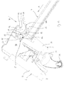
- a window according to the invention includes a frame 1 and a sash 2 represented in Figs 1 and 2 by a frame top member 11 and a sash top member 21.
- a ventilation flap 25 and a handle bar 26 on the sash top member are connected to a locking assembly 7 interconnecting the frame and the sash top members in a manner known per se.
- the pane 3 is attached to the sash top member 21 with a glazing profile 8 and it is to be understood that similar profiles are used at the sides as shown in Fig. 3 and at the bottom of the window.
- a frame top covering member 41 Attached to the exterior side of the frame top member 11 is a frame top covering member 41, which covers the spacing between the frame top member 11 and the sash top member 21 as well as the glazing profile 8.
- a leg 42 of the covering member 41 projects towards the pane 3 so that a lower edge 43 thereof is located directly above the outer edge 81 of the glazing profile.
- a gaskets carrier 44 carrying a sealing gasket 45 is provided on the interior side of the frame top covering member 41 so that the sealing gasket is in engagement with an upstanding leg 82 of the glazing profile 8 in the closed state of the window.
- the sealing gasket is here shown in its initial state it is to be understood that it will be compressed by the contact with the glazing profile.
- the window may also be made without such a sealing gasket and carrier and/or that a ventilation restriction means such as the baffle systems described in wO08133539A1 and EP2317026B1 may be provided.
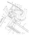
- a gasket-like diversion member 6 is arranged in the glazing profile 8 with a first portion 61 arranged in a groove in the glazing profile formed by the inner upper leg 82 and a second upstanding leg 83 formed by a bent section 84.
- the shape of the interior side of the diversion member corresponds closely to the shape of the exterior side of the glazing profile, which provide for an easy and reliable attachment.
- the diversion member could however also be attached to the exterior side of the pane 3 or directly to the sash top member 21, which might for example be the case if the pane were attached without the use of a glazing profile. Likewise, it is to be understood that the diversion may be in contact with the pane even if attached to a glazing profile as shown.
- a second portion 62 of the diversion member projects from the bent section 84 of the glazing profile out over the exterior side of the pane 3 and an angle ⁇ thereto so that a wedge shaped space 31 is formed between the second portion and the pane.
- the second portion could in principle be at straight section or have a triangular cross-sectional shape, but in this embodiment it is curved so that the section closest to the distal edge 63 is substantially perpendicular to the plane of the pane.
- the ventilation opening 51 formed between the lower edge 43 of the projecting leg 42 of the frame top covering member 41 and the lower edge 81 of the glazing profile is completely covered when seen in a direction in parallel with the pane 3 as indicated to by the arrow A.
- an opening of the same size as the original ventilation opening 51 is present between the distal edge 63 of the second portion 62 of the diversion member 6 and the projecting leg 42 of the frame top covering member 41. This means that amount of air, which can pass through the ventilation opening 51 and hence the ventilation passage 52 is substantially the same as without the diversion member.
- a curved shape is also found on the exterior side 65 of the second portion, which ends in a projection 64 at the proximal edge above the bent section 84 of the glazing profile, so that the exterior side of the diversion member forms a gutter.
- This gutter is substantially centred under the lower edge 43 of the projecting leg 42 of the frame top covering member 41 and is therefore capable of collecting water draining off from the frame top covering member.
- the diversion member 6 is of a hollow design with intermediate walls interconnection two surface walls of the second portion 62.
- This design is particularly suited for giving a rubber member dimensional stability, but it is to be understood that it may also be used with different materials and/or that the diversion member may be solid, made for example of rubber foam. Moreover, the diversion member may be made with inlays of different kinds and materials in order to achieve the desired properties.
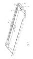
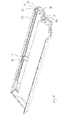
- FIG. 3 the upper left-hand corner of a window is shown with the covering members removed so that the gutter formed by the exterior side 65 of the second portion 62 of the diversion member is clearly seen.
- Water in the gutter may be drained off as shown by the arrows C either by flowing over the end edges 66 (only one of which are visible) of the diversion member and onto the glazing profiles 8 at the sides of the window or through drainage openings 67 penetrating through the second portion. It would, however also be possible to make the gutter with closed ends or without the drainage openings.
- the drainage openings shown here are relative small to hinder water from penetrating into the gutter from below, but it would also be possible to provide them with a valve function.
- the first portion 61 is here somewhat shorter than the second portion 62 of the diversion member to facilitate assembly of the window, but this need not be the case.
- a mechanical locking member is shown in Figs 4 and 5 . It consists of an oval plate member 9 with a first width d1, which is slightly smaller than the width w of the opening of the groove 86 in the glazing profile with mounted diversion member, and a second width d2, which is equal to or slightly larger than the width of the opening.
- a first width d1 which is slightly smaller than the width w of the opening of the groove 86 in the glazing profile with mounted diversion member
- a second width d2 which is equal to or slightly larger than the width of the opening.
- For attaching the locking member 9 it is inserted in the groove 86 with it largest width substantially in parallel with the longitudinal direction of the groove as shown in Fig. 4 . It is then turned approximately 90 degrees to the position in Fig. 5 , where it is clamped in a tight-fitting manner between the two legs of the glazing profile forming the groove.
- a common screw driver engaging the slit 91 at the centre of the plate may be used for turning it.
- the projecting leg 82 of the glazing profile 8 has a bent edge 85 projecting over the groove 86 and defining a groove opening with a width w, which is smaller than the width at the bottom of the groove.
- This bent edge contributes to retaining the locking member 9 in the fixed state by preventing it from moving upwards out of the groove, but it will be understood that it is not necessary.
- the diversion member 6 is here of a design covering the inner surface of the groove 86, i.e. the exterior side of the glazing profile 8, resulting in the actual width w of the groove opening being somewhat smaller than the distance between the walls of the glazing profile 8.
- the width of the opening of the groove in the glazing profile it is to be understood as meaning the actual available width of the opening.
- the first portion of the diversion member is here made with a leg 68 lying closely against the inner side of the upper leg 82 on the glazing profile and is retained by the bent edge 85. When made of rubber, it serves as an anti-slip member contributing to keeping the locking member 9 in place.
- a small groove 68' in the leg 68 and a bead 69 on the diversion member at the opposite side of the groove 86 are specially adapted for retaining a plate-shaped locking member. This means that the first portion 61 of the diversion member is clamped between the glazing profile 8 and the plate member 9, thus contributing to increased friction between the glazing profile and the diversion member and consequently a more secure attachment.
- the resilience of a rubber diversion member will help to establish a tight-fitting engagement between the glazing profile, the diversion member and the locking member.
- the advantages of the small groove 68' and the bead 69 on the diversion member 6 also applies to embodiments of the invention, where the diversion member is made from a different material than rubber or where the rubber is used in combination with other materials.
- the small groove and bead should, however, not be regarded as a necessary part of a diversion member according to the invention.
- FIGs 6-8 Another embodiment of a locking member 109 is shown in Figs 6-8 , where like features have been given the same reference numbers as in Figs 1-5 , but with 100 added. Where nothing else is stated, such features have the same properties as explained above with reference to Figs 1-5 .
- the locking member 109 is of a elongated rounded shape with a slit 191 at the centre just as the one in Figs 4 and 5 and it is inserted and locked in the same way.
- the difference lies in the shape of the sides coming into engagement with the diversion member 106 and/or glazing profile 108, when the locking member is turned.
- these sides have been made with concave recesses 192, so that two contact points 193 are formed at the transition between the longer convex sides 194 and the recesses 192 forming the shorter concave sides.
- this shape means that there are two points of contact on each side, which leads to a particularly secure attachment of the locking member and hence the diversion member. Not only is the contact surface and hence the friction larger; the distance between the contact points also prevents the locking member from gradually and unintentionally moving towards the unsecured position under the influence of thermal expansion, the tension of the material of the diversion member and the glazing list, etc.
- the invention has been illustrated with reference to a centre-hung roof window, where the top members of the frame and the sash move away from each other when the window is opened, but it may also be used on other types of windows such as top-hung windows, windows having a hinge axis between the centre and the top or a dual function window capable of being operated both as centre-hung and top-hung.
- the diversion member has been described with reference to its primary intended use, i.e. to divert water, which is pressed upwards on the exterior surface of the pane. It will, however, be understood that the diversion member will also divert air and that it may therefore contribute to preventing draught caused by wind blowing directly into the ventilation opening and potentially improve the insulating properties of the window.
Landscapes
- Engineering & Computer Science (AREA)
- Civil Engineering (AREA)
- Structural Engineering (AREA)
- Architecture (AREA)
- Specific Sealing Or Ventilating Devices For Doors And Windows (AREA)
- Securing Of Glass Panes Or The Like (AREA)
Applications Claiming Priority (1)
| Application Number | Priority Date | Filing Date | Title |
|---|---|---|---|
| DK201370293A DK178249B1 (en) | 2013-05-29 | 2013-05-29 | A roof window with a water diversion member |
Publications (2)
| Publication Number | Publication Date |
|---|---|
| EP2808461A1 true EP2808461A1 (de) | 2014-12-03 |
| EP2808461B1 EP2808461B1 (de) | 2016-06-29 |
Family
ID=50774781
Family Applications (1)
| Application Number | Title | Priority Date | Filing Date |
|---|---|---|---|
| EP14170145.8A Active EP2808461B1 (de) | 2013-05-29 | 2014-05-28 | Dachfenster mit Wasserumleitungselement |
Country Status (4)
| Country | Link |
|---|---|
| EP (1) | EP2808461B1 (de) |
| CN (2) | CN204139471U (de) |
| DK (1) | DK178249B1 (de) |
| PL (1) | PL2808461T3 (de) |
Cited By (2)
| Publication number | Priority date | Publication date | Assignee | Title |
|---|---|---|---|---|
| EP3179004A1 (de) * | 2015-12-09 | 2017-06-14 | Keylite Roof Windows Limited | Abdeckung für ein dachfenster |
| CN113123537A (zh) * | 2019-12-30 | 2021-07-16 | Vkr控股公司 | 具有邻近屋顶窗户安装的通风单元的屋顶窗户系统及其提供和改装方法、包括其的屋顶结构 |
Families Citing this family (1)
| Publication number | Priority date | Publication date | Assignee | Title |
|---|---|---|---|---|
| CN113490780B (zh) * | 2019-02-26 | 2022-11-29 | Gdx有限责任公司 | 用于屋顶通风的固定件 |
Citations (4)
| Publication number | Priority date | Publication date | Assignee | Title |
|---|---|---|---|---|
| FR2269628A1 (en) * | 1974-05-02 | 1975-11-28 | Hoeganaes Ab | Hinged type skylight cladding - has U-shaped section on fixed frame with flange held by roof hatch collar |
| EP1355016A2 (de) * | 2002-04-17 | 2003-10-22 | Roto Frank Ag | Dachfenster mit geklipster Abdeckung |
| WO2008133539A2 (en) | 2007-04-27 | 2008-11-06 | Fakro Pp Spolka Z O. O. | Roof window with air supply channel |
| EP2317026B1 (de) | 2009-11-02 | 2012-06-06 | VKR Holding A/S | Lüftungsgerät und Dachfenstersystem |
Family Cites Families (3)
| Publication number | Priority date | Publication date | Assignee | Title |
|---|---|---|---|---|
| SE378644B (de) * | 1973-10-02 | 1975-09-08 | S A Hogedal | |
| EP0969178A1 (de) * | 1998-06-30 | 2000-01-05 | VELUX Industri A/S | Ein Fenster mit einer Ventilationsklappe und einem einbruchhemmenden Element |
| PL227908B1 (pl) * | 2011-08-05 | 2018-01-31 | Fakro Pp Spólka Z Ograniczona Odpowiedzialnoscia | Zespół osłon ramiaków bocznych okna dachowego |
-
2013
- 2013-05-29 DK DK201370293A patent/DK178249B1/en active
-
2014
- 2014-05-28 PL PL14170145.8T patent/PL2808461T3/pl unknown
- 2014-05-28 EP EP14170145.8A patent/EP2808461B1/de active Active
- 2014-05-29 CN CN201420283759.0U patent/CN204139471U/zh not_active Expired - Lifetime
- 2014-05-29 CN CN201420282585.6U patent/CN204139470U/zh not_active Expired - Lifetime
Patent Citations (4)
| Publication number | Priority date | Publication date | Assignee | Title |
|---|---|---|---|---|
| FR2269628A1 (en) * | 1974-05-02 | 1975-11-28 | Hoeganaes Ab | Hinged type skylight cladding - has U-shaped section on fixed frame with flange held by roof hatch collar |
| EP1355016A2 (de) * | 2002-04-17 | 2003-10-22 | Roto Frank Ag | Dachfenster mit geklipster Abdeckung |
| WO2008133539A2 (en) | 2007-04-27 | 2008-11-06 | Fakro Pp Spolka Z O. O. | Roof window with air supply channel |
| EP2317026B1 (de) | 2009-11-02 | 2012-06-06 | VKR Holding A/S | Lüftungsgerät und Dachfenstersystem |
Cited By (3)
| Publication number | Priority date | Publication date | Assignee | Title |
|---|---|---|---|---|
| EP3179004A1 (de) * | 2015-12-09 | 2017-06-14 | Keylite Roof Windows Limited | Abdeckung für ein dachfenster |
| CN113123537A (zh) * | 2019-12-30 | 2021-07-16 | Vkr控股公司 | 具有邻近屋顶窗户安装的通风单元的屋顶窗户系统及其提供和改装方法、包括其的屋顶结构 |
| CN113123537B (zh) * | 2019-12-30 | 2024-03-29 | Vkr控股公司 | 具有邻近屋顶窗户安装的通风单元的屋顶窗户系统及其提供和改装方法、包括其的屋顶结构 |
Also Published As
| Publication number | Publication date |
|---|---|
| CN204139471U (zh) | 2015-02-04 |
| DK178249B1 (en) | 2015-10-05 |
| PL2808461T3 (pl) | 2016-12-30 |
| DK201370293A1 (en) | 2014-12-15 |
| CN204139470U (zh) | 2015-02-04 |
| EP2808461B1 (de) | 2016-06-29 |
Similar Documents
| Publication | Publication Date | Title |
|---|---|---|
| CA2043030C (en) | Self draining door threshold | |
| US6061967A (en) | Overhead door sealing assembly | |
| EP3396100B1 (de) | Flachdachfenster mit äussere abdeckung | |
| EP2808461B1 (de) | Dachfenster mit Wasserumleitungselement | |
| EP2751354B1 (de) | Dachfenster mit verbesserter schlagwulstabdeckung | |
| US9151049B2 (en) | Roof window with an insulating element | |
| US8291658B1 (en) | Electrical conduit flashing system | |
| EP3039201B1 (de) | Zum einbau in eine geneigte oberfläche eines gebäudes angepasstes fenstersystem und verfahren zum ablassen von kondenswasser aus solch einem fenstersystem | |
| KR100562712B1 (ko) | 악취방지용 덮개 | |
| JPS6118520A (ja) | 車輌屋根用のたわまないカバ− | |
| DE202012006688U1 (de) | Dachfenster mit Abdeckmitteln für einen Rahmen | |
| CA2907280A1 (en) | Eavestrough with a gutter sheild | |
| JP3195254U (ja) | フレーム用のカバー手段を有する屋根窓 | |
| EP2578764B1 (de) | Dachfenster mit einem Passbolzen | |
| EP2242889B1 (de) | Wetterschutz | |
| US4393754A (en) | Air deflection assembly for vehicle sunroofs | |
| EP2762653B1 (de) | Dachfensteranordnung mit Lüfter | |
| US20060156639A1 (en) | Flexible flashings for windows and the like | |
| NZ546560A (en) | Water drain device for a sliding door frame | |
| EP3473795B1 (de) | Anti-sickerwasser-system für einen türrahmen | |
| DE202012006675U1 (de) | Dachfenster mit einer verbesserten Abdeckung für eine Schlagleiste am Rahmen | |
| EP2982811A1 (de) | Dampfsperre für ein dachfenster | |
| EP4283069A1 (de) | Haube für ein dachfenster | |
| KR100926581B1 (ko) | 창틀 시스템 | |
| DE202012009491U1 (de) | Untere Fensterflügeldichtung und Dachfenster mit unterer Fensterflügeldichtung |
Legal Events
| Date | Code | Title | Description |
|---|---|---|---|
| PUAI | Public reference made under article 153(3) epc to a published international application that has entered the european phase |
Free format text: ORIGINAL CODE: 0009012 |
|
| 17P | Request for examination filed |
Effective date: 20140528 |
|
| AK | Designated contracting states |
Kind code of ref document: A1 Designated state(s): AL AT BE BG CH CY CZ DE DK EE ES FI FR GB GR HR HU IE IS IT LI LT LU LV MC MK MT NL NO PL PT RO RS SE SI SK SM TR |
|
| AX | Request for extension of the european patent |
Extension state: BA ME |
|
| R17P | Request for examination filed (corrected) |
Effective date: 20150603 |
|
| RBV | Designated contracting states (corrected) |
Designated state(s): AL AT BE BG CH CY CZ DE DK EE ES FI FR GB GR HR HU IE IS IT LI LT LU LV MC MK MT NL NO PL PT RO RS SE SI SK SM TR |
|
| GRAP | Despatch of communication of intention to grant a patent |
Free format text: ORIGINAL CODE: EPIDOSNIGR1 |
|
| INTG | Intention to grant announced |
Effective date: 20150730 |
|
| INTG | Intention to grant announced |
Effective date: 20160115 |
|
| GRAS | Grant fee paid |
Free format text: ORIGINAL CODE: EPIDOSNIGR3 |
|
| GRAA | (expected) grant |
Free format text: ORIGINAL CODE: 0009210 |
|
| AK | Designated contracting states |
Kind code of ref document: B1 Designated state(s): AL AT BE BG CH CY CZ DE DK EE ES FI FR GB GR HR HU IE IS IT LI LT LU LV MC MK MT NL NO PL PT RO RS SE SI SK SM TR |
|
| REG | Reference to a national code |
Ref country code: GB Ref legal event code: FG4D |
|
| REG | Reference to a national code |
Ref country code: CH Ref legal event code: EP |
|
| REG | Reference to a national code |
Ref country code: AT Ref legal event code: REF Ref document number: 809239 Country of ref document: AT Kind code of ref document: T Effective date: 20160715 |
|
| REG | Reference to a national code |
Ref country code: IE Ref legal event code: FG4D |
|
| REG | Reference to a national code |
Ref country code: DE Ref legal event code: R096 Ref document number: 602014002458 Country of ref document: DE |
|
| REG | Reference to a national code |
Ref country code: NL Ref legal event code: FP |
|
| REG | Reference to a national code |
Ref country code: LT Ref legal event code: MG4D |
|
| PG25 | Lapsed in a contracting state [announced via postgrant information from national office to epo] |
Ref country code: LT Free format text: LAPSE BECAUSE OF FAILURE TO SUBMIT A TRANSLATION OF THE DESCRIPTION OR TO PAY THE FEE WITHIN THE PRESCRIBED TIME-LIMIT Effective date: 20160629 Ref country code: NO Free format text: LAPSE BECAUSE OF FAILURE TO SUBMIT A TRANSLATION OF THE DESCRIPTION OR TO PAY THE FEE WITHIN THE PRESCRIBED TIME-LIMIT Effective date: 20160929 Ref country code: FI Free format text: LAPSE BECAUSE OF FAILURE TO SUBMIT A TRANSLATION OF THE DESCRIPTION OR TO PAY THE FEE WITHIN THE PRESCRIBED TIME-LIMIT Effective date: 20160629 |
|
| PG25 | Lapsed in a contracting state [announced via postgrant information from national office to epo] |
Ref country code: HR Free format text: LAPSE BECAUSE OF FAILURE TO SUBMIT A TRANSLATION OF THE DESCRIPTION OR TO PAY THE FEE WITHIN THE PRESCRIBED TIME-LIMIT Effective date: 20160629 Ref country code: SE Free format text: LAPSE BECAUSE OF FAILURE TO SUBMIT A TRANSLATION OF THE DESCRIPTION OR TO PAY THE FEE WITHIN THE PRESCRIBED TIME-LIMIT Effective date: 20160629 Ref country code: LV Free format text: LAPSE BECAUSE OF FAILURE TO SUBMIT A TRANSLATION OF THE DESCRIPTION OR TO PAY THE FEE WITHIN THE PRESCRIBED TIME-LIMIT Effective date: 20160629 Ref country code: GR Free format text: LAPSE BECAUSE OF FAILURE TO SUBMIT A TRANSLATION OF THE DESCRIPTION OR TO PAY THE FEE WITHIN THE PRESCRIBED TIME-LIMIT Effective date: 20160930 Ref country code: RS Free format text: LAPSE BECAUSE OF FAILURE TO SUBMIT A TRANSLATION OF THE DESCRIPTION OR TO PAY THE FEE WITHIN THE PRESCRIBED TIME-LIMIT Effective date: 20160629 |
|
| REG | Reference to a national code |
Ref country code: AT Ref legal event code: MK05 Ref document number: 809239 Country of ref document: AT Kind code of ref document: T Effective date: 20160629 |
|
| PG25 | Lapsed in a contracting state [announced via postgrant information from national office to epo] |
Ref country code: CZ Free format text: LAPSE BECAUSE OF FAILURE TO SUBMIT A TRANSLATION OF THE DESCRIPTION OR TO PAY THE FEE WITHIN THE PRESCRIBED TIME-LIMIT Effective date: 20160629 Ref country code: IT Free format text: LAPSE BECAUSE OF FAILURE TO SUBMIT A TRANSLATION OF THE DESCRIPTION OR TO PAY THE FEE WITHIN THE PRESCRIBED TIME-LIMIT Effective date: 20160629 Ref country code: SK Free format text: LAPSE BECAUSE OF FAILURE TO SUBMIT A TRANSLATION OF THE DESCRIPTION OR TO PAY THE FEE WITHIN THE PRESCRIBED TIME-LIMIT Effective date: 20160629 Ref country code: RO Free format text: LAPSE BECAUSE OF FAILURE TO SUBMIT A TRANSLATION OF THE DESCRIPTION OR TO PAY THE FEE WITHIN THE PRESCRIBED TIME-LIMIT Effective date: 20160629 Ref country code: EE Free format text: LAPSE BECAUSE OF FAILURE TO SUBMIT A TRANSLATION OF THE DESCRIPTION OR TO PAY THE FEE WITHIN THE PRESCRIBED TIME-LIMIT Effective date: 20160629 Ref country code: IS Free format text: LAPSE BECAUSE OF FAILURE TO SUBMIT A TRANSLATION OF THE DESCRIPTION OR TO PAY THE FEE WITHIN THE PRESCRIBED TIME-LIMIT Effective date: 20161029 |
|
| PG25 | Lapsed in a contracting state [announced via postgrant information from national office to epo] |
Ref country code: SM Free format text: LAPSE BECAUSE OF FAILURE TO SUBMIT A TRANSLATION OF THE DESCRIPTION OR TO PAY THE FEE WITHIN THE PRESCRIBED TIME-LIMIT Effective date: 20160629 Ref country code: ES Free format text: LAPSE BECAUSE OF FAILURE TO SUBMIT A TRANSLATION OF THE DESCRIPTION OR TO PAY THE FEE WITHIN THE PRESCRIBED TIME-LIMIT Effective date: 20160629 Ref country code: PT Free format text: LAPSE BECAUSE OF FAILURE TO SUBMIT A TRANSLATION OF THE DESCRIPTION OR TO PAY THE FEE WITHIN THE PRESCRIBED TIME-LIMIT Effective date: 20161031 Ref country code: AT Free format text: LAPSE BECAUSE OF FAILURE TO SUBMIT A TRANSLATION OF THE DESCRIPTION OR TO PAY THE FEE WITHIN THE PRESCRIBED TIME-LIMIT Effective date: 20160629 Ref country code: BE Free format text: LAPSE BECAUSE OF FAILURE TO SUBMIT A TRANSLATION OF THE DESCRIPTION OR TO PAY THE FEE WITHIN THE PRESCRIBED TIME-LIMIT Effective date: 20160629 |
|
| REG | Reference to a national code |
Ref country code: DE Ref legal event code: R097 Ref document number: 602014002458 Country of ref document: DE |
|
| REG | Reference to a national code |
Ref country code: FR Ref legal event code: PLFP Year of fee payment: 4 |
|
| PG25 | Lapsed in a contracting state [announced via postgrant information from national office to epo] |
Ref country code: DK Free format text: LAPSE BECAUSE OF FAILURE TO SUBMIT A TRANSLATION OF THE DESCRIPTION OR TO PAY THE FEE WITHIN THE PRESCRIBED TIME-LIMIT Effective date: 20160629 |
|
| 26N | No opposition filed |
Effective date: 20170330 |
|
| PLBE | No opposition filed within time limit |
Free format text: ORIGINAL CODE: 0009261 |
|
| STAA | Information on the status of an ep patent application or granted ep patent |
Free format text: STATUS: NO OPPOSITION FILED WITHIN TIME LIMIT |
|
| PG25 | Lapsed in a contracting state [announced via postgrant information from national office to epo] |
Ref country code: LU Free format text: LAPSE BECAUSE OF NON-PAYMENT OF DUE FEES Effective date: 20170531 Ref country code: SI Free format text: LAPSE BECAUSE OF FAILURE TO SUBMIT A TRANSLATION OF THE DESCRIPTION OR TO PAY THE FEE WITHIN THE PRESCRIBED TIME-LIMIT Effective date: 20160629 Ref country code: BG Free format text: LAPSE BECAUSE OF FAILURE TO SUBMIT A TRANSLATION OF THE DESCRIPTION OR TO PAY THE FEE WITHIN THE PRESCRIBED TIME-LIMIT Effective date: 20160929 |
|
| REG | Reference to a national code |
Ref country code: CH Ref legal event code: PL |
|
| PG25 | Lapsed in a contracting state [announced via postgrant information from national office to epo] |
Ref country code: MC Free format text: LAPSE BECAUSE OF FAILURE TO SUBMIT A TRANSLATION OF THE DESCRIPTION OR TO PAY THE FEE WITHIN THE PRESCRIBED TIME-LIMIT Effective date: 20160629 |
|
| REG | Reference to a national code |
Ref country code: IE Ref legal event code: MM4A |
|
| PG25 | Lapsed in a contracting state [announced via postgrant information from national office to epo] |
Ref country code: LI Free format text: LAPSE BECAUSE OF NON-PAYMENT OF DUE FEES Effective date: 20170531 Ref country code: CH Free format text: LAPSE BECAUSE OF NON-PAYMENT OF DUE FEES Effective date: 20170531 |
|
| PG25 | Lapsed in a contracting state [announced via postgrant information from national office to epo] |
Ref country code: LU Free format text: LAPSE BECAUSE OF NON-PAYMENT OF DUE FEES Effective date: 20170528 |
|
| PG25 | Lapsed in a contracting state [announced via postgrant information from national office to epo] |
Ref country code: IE Free format text: LAPSE BECAUSE OF NON-PAYMENT OF DUE FEES Effective date: 20170528 |
|
| REG | Reference to a national code |
Ref country code: FR Ref legal event code: PLFP Year of fee payment: 5 |
|
| PG25 | Lapsed in a contracting state [announced via postgrant information from national office to epo] |
Ref country code: MT Free format text: LAPSE BECAUSE OF NON-PAYMENT OF DUE FEES Effective date: 20170528 |
|
| PG25 | Lapsed in a contracting state [announced via postgrant information from national office to epo] |
Ref country code: AL Free format text: LAPSE BECAUSE OF FAILURE TO SUBMIT A TRANSLATION OF THE DESCRIPTION OR TO PAY THE FEE WITHIN THE PRESCRIBED TIME-LIMIT Effective date: 20160629 |
|
| GBPC | Gb: european patent ceased through non-payment of renewal fee |
Effective date: 20180528 |
|
| PG25 | Lapsed in a contracting state [announced via postgrant information from national office to epo] |
Ref country code: GB Free format text: LAPSE BECAUSE OF NON-PAYMENT OF DUE FEES Effective date: 20180528 |
|
| PG25 | Lapsed in a contracting state [announced via postgrant information from national office to epo] |
Ref country code: HU Free format text: LAPSE BECAUSE OF FAILURE TO SUBMIT A TRANSLATION OF THE DESCRIPTION OR TO PAY THE FEE WITHIN THE PRESCRIBED TIME-LIMIT; INVALID AB INITIO Effective date: 20140528 |
|
| PG25 | Lapsed in a contracting state [announced via postgrant information from national office to epo] |
Ref country code: CY Free format text: LAPSE BECAUSE OF FAILURE TO SUBMIT A TRANSLATION OF THE DESCRIPTION OR TO PAY THE FEE WITHIN THE PRESCRIBED TIME-LIMIT Effective date: 20160629 |
|
| PG25 | Lapsed in a contracting state [announced via postgrant information from national office to epo] |
Ref country code: MK Free format text: LAPSE BECAUSE OF FAILURE TO SUBMIT A TRANSLATION OF THE DESCRIPTION OR TO PAY THE FEE WITHIN THE PRESCRIBED TIME-LIMIT Effective date: 20160629 |
|
| PG25 | Lapsed in a contracting state [announced via postgrant information from national office to epo] |
Ref country code: TR Free format text: LAPSE BECAUSE OF FAILURE TO SUBMIT A TRANSLATION OF THE DESCRIPTION OR TO PAY THE FEE WITHIN THE PRESCRIBED TIME-LIMIT Effective date: 20160629 |
|
| PGFP | Annual fee paid to national office [announced via postgrant information from national office to epo] |
Ref country code: FR Payment date: 20230421 Year of fee payment: 10 Ref country code: DE Payment date: 20230404 Year of fee payment: 10 |
|
| PGFP | Annual fee paid to national office [announced via postgrant information from national office to epo] |
Ref country code: PL Payment date: 20230417 Year of fee payment: 10 |
|
| PGFP | Annual fee paid to national office [announced via postgrant information from national office to epo] |
Ref country code: NL Payment date: 20240415 Year of fee payment: 11 |